

Page 1

LBI-39128
Installation & Operation
EDACS
Power Monitor Unit
ericssonzericssonz
Page 2

LBI-39128 CONTENTS
TABLE OF CONTENTS
INTRODUCTION....................................................................................................................................... 6
DESCRIPTION........................................................................................................................................... 6
APPLICATION NOTES............................................................................................................................. 7
VAX SITE CONTROLLER COMPUTER.......................................................................................... 7
APPLICATION SOFTWARE PROMS............................................................................................... 7
PERSONALITY PROMS .................................................................................................................... 7
INSTALLATION........................................................................................................................................ 8
SITE CONTROLLER HARDWARE................................................................................................... 8
SITE CONTROLLER SOFTWARE.................................................................................................... 8
Application Software PROMs....................................................................................................... 9
Personality PROMs....................................................................................................................... 9
PMU HARDWARE ............................................................................................................................. 9
A. Addition from No PMU............................................................................................................ 9
B. Upgrade from Old PMU........................................................................................................... 12
C. Adaptation from Old PMU ....................................................................................................... 13
INITIAL POWER-UP.......................................................................................................................... 14
PMU PROGRAMMING...................................................................................................................... 15
Terminal Setup.............................................................................................................................. 15
Software Initialization ................................................................................................................... 15
Time/Date/Password...................................................................................................................... 17
Antenna Mapping.......................................................................................................................... 18
POWER SENSOR CALIBRATION.................................................................................................... 19
Unidirectional Power Sensors ....................................................................................................... 19
Bi-directional Power Sensors ........................................................................................................ 20
FINAL CHECK.................................................................................................................................... 21
(Continued)
Page
NOTICE
NOTICE
This Manual covers Ericsson and General Electric products manufactured and sold by Ericsson Inc.
This Manual covers Ericsson and General Electric products manufactured and sold by Ericsson Inc.
NOTICE
NOTICE
Repairs to this equipment should be made only by an authorized service technician or facility designated by the supplier. Any
Repairs to this equipment should be made only by an authorized service technician or facility designated by the supplier. Any
repairs, alterations or substitution of recommended parts made by the user to this equipment not approved by the
repairs, alterations or substitution of recommended parts made by the user to this equipment not approved by the
manufacturer could void the user’s authority to operate the equipment in addition to the manufacturer’s warranty.
manufacturer could void the user’s authority to operate the equipment in addition to the manufacturer’s warranty.
NOTICE!
NOTICE!
The software contained in this device is copyrighted by Ericsson Inc. Unpublished rights are reserved under the copyright
The software contained in this device is copyrighted by Ericsson Inc. Unpublished rights are reserved under the copyright
laws of the United States.
laws of the United States.
This manual is published by
This manual is published by
inaccuracies of current information, or improvements to programs and/or equipment, may be made by
inaccuracies of current information, or improvements to programs and/or equipment, may be made by
changes will be incorporated into new editions of this manual. No part of this manual may be reproduced or transmitted in any form or by any means,
changes will be incorporated into new editions of this manual. No part of this manual may be reproduced or transmitted in any form or by any means,
electronic or mechanical, including photocopying and recording, for any purpose, without the express written permission of
electronic or mechanical, including photocopying and recording, for any purpose, without the express written permission of
Copyright March 1995, Ericsson Inc.
Ericsson Inc.
Ericsson Inc.
, without any warranty. Improvements and changes to this manual necessitated by typographical errors,
, without any warranty. Improvements and changes to this manual necessitated by typographical errors,
Ericsson Inc.
Ericsson Inc.
, at any time and without notice. Such
, at any time and without notice. Such
Ericsson Inc.
Ericsson Inc.
2
Page 3

CONTENTS LBI-39128
TABLE OF CONTENTS (Cont.)
Page
OPERATION.............................................................................................................................................. 22
STARTUP............................................................................................................................................ 22
Polling Recovery........................................................................................................................... 22
EDACS Configuration Setup ........................................................................................................ 22
Polling Failure............................................................................................................................... 22
MONITOR........................................................................................................................................... 22
Power Sensor Monitoring.............................................................................................................. 22
Power Measurements .................................................................................................................... 23
SWR Calculations......................................................................................................................... 23
ALARMS............................................................................................................................................. 23
Alarm Reporting............................................................................................................................ 24
Excessive Alarms.......................................................................................................................... 24
PARAMETERS ................................................................................................................................... 25
Channel PMU Enable.................................................................................................................... 25
Site PMU Enable........................................................................................................................... 25
PMU Model .................................................................................................................................. 25
Transmitter Lower Alarm Limit.................................................................................................... 27
Transmitter Upper Alarm Limit .................................................................................................... 27
Antenna Lower Alarm Limit......................................................................................................... 27
Antenna Upper Alarm Limit ......................................................................................................... 27
SWR Upper Alarm Limit.............................................................................................................. 28
Antenna Mapping.......................................................................................................................... 28
ALARM LIMIT RE-CONFIGURATION ........................................................................................... 28
Alarm Limits As Installed............................................................................................................. 28
Transmitter Power Alarm Limits................................................................................................... 28
Antenna Power Alarm Limits........................................................................................................ 28
Antenna SWR Alarm Limit........................................................................................................... 29
MAINTENANCE........................................................................................................................................ 30
POWER SENSOR CALIBRATION.................................................................................................... 30
TIME AND DATE ADJUSTMENT.................................................................................................... 30
DIAGNOSTIC SCREENS................................................................................................................... 30
Alarm History Report Screen........................................................................................................ 30
Channel Monitor Screen................................................................................................................ 30
SOFTWARE UPDATES ..................................................................................................................... 32
ERASE ALL PROGRAMMING ......................................................................................................... 32
ALARM DELAY ADJUSTMENT...................................................................................................... 33
TROUBLESHOOTING....................................................................................................................... 34
GLOSSARY................................................................................................................................................ 36
PMU INTERCONNECT DIAGRAM - EDACS REPEATER CABINET ................................................. 37
PMU INTERCONNECT DIAGRAM - SITE CONTROLLER CABINET (Upgrade) .............................. 38
3
Page 4

LBI-39128 FIGURES AND TABLES
LIST OF FIGURES AND TABLES
Figure 1 - Location of PMU Components.................................................................................................... 6
Figure 2 - Card Layout for PDP Upgraded to VAX .................................................................................... 7
Figure 3 - Location of Fastener Screws on Computer.................................................................................. 8
Figure 4 - Location of PROM Card in Computer ........................................................................................ 8
Figure 5 - Location of PROM Card in Older Computer.............................................................................. 8
Figure 6 - Location of PROMs on PROM Card .......................................................................................... 8
Figure 7 - Application Software PROM Label ............................................................................................ 9
Figure 8 - Personality PROM Label ............................................................................................................ 9
Figure 9 - Antenna Power Sensor Connections............................................................................................ 11
Figure 10 - Connections for Addition from No PMU.................................................................................. 12
Figure 11 - Connections for Upgrade from Old PMU................................................................................. 13
Figure 12 - Connections for Adaptation from Old PMU ............................................................................. 14
Figure 13 - DB-25 Terminal Connections ................................................................................................... 15
Figure 14 - DB-9 Terminal Connections ..................................................................................................... 15
Figure 15 - Operation Select Menu (Main Menu) ....................................................................................... 16
Figure 16 - Setup Selection Menu ............................................................................................................... 16
Figure 17 - Site Data #1 Screen................................................................................................................... 17
Figure 18 - Analog Input Channel Screen.................................................................................................... 18
Figure 19 - Analog Input Channel Screen Showing Antenna Channel Parameter ....................................... 19
Figure 20 - Unidirectional Power Sensor Calibration Screw....................................................................... 19
Figure 21 - Bi-directional Power Sensor Calibration Screws ...................................................................... 20
Figure 22 - Analog Pseudo Channel Screen ................................................................................................ 29
Figure 23 - Report Selection Menu.............................................................................................................. 31
Figure 24 - Alarm History Report Screen.................................................................................................... 31
Figure 25 - Channel Monitor Screen............................................................................................................ 31
Figure 26 - Location of PMU Software....................................................................................................... 32
Figure 27 - Location of DIP Switches ......................................................................................................... 33
Page
Table 1 - Selection of Installation Procedure............................................................................................... 9
Table 2 - Parts for Addition from No PMU................................................................................................. 10
Table 3 - Parts for Upgrade from Old PMU................................................................................................ 12
Table 4 - Parts for Adaptation from Old PMU............................................................................................ 13
Table 5 - Terminal Communications Protocol............................................................................................. 15
Table 6 - Power Sensor Voltage-to-Power Conversion Table..................................................................... 21
Table 7 - PMU Option Parameters .............................................................................................................. 26
Table 8 - SWR Upper Limit ........................................................................................................................ 30
Table 9 - Channel Numbers for Channel Monitor Screen............................................................................ 32
Table 10 - Troubleshooting Symptoms........................................................................................................ 34
4
Page 5

PMU:
Mechanical:
Width ............................................................ 19 in. (482.6 mm)
Height............................................................3.5 in. (88.9 mm)
Depth............................................................. 6 in. (152.4 mm)
Weight........................................................... < 5 lb. (2.27 kg)
Environmental:
Temperature Range.......................................0° to 60° C (32° to 140° F)
Relative Humidity.........................................0 to 95%
Power Requirements:
External.........................................................12 Watts (max.) at 12 Vdc (nominal)
RAM Battery Life .........................................3 years
Power Sensors:
19C336861P2 - Unidirectional
Frequency Range........................................... 450 to 1000 MHz
Maximum Power...........................................1000 Watts
19C336861P3 - Bi-directional
Frequency Range........................................... 450 to 1000 MHz
Maximum Power...........................................1000 Watts
19C336861P4 - Bi-directional
Frequency Range........................................... 66 to 325 MHz
Maximum Power...........................................1000 Watts
SPECIFICATIONS LBI-39128
SPECIFICATIONS
Data Interfaces:
Site Controller Computer:
Baud Rate...................................................... 9600
Data Bits........................................................8
Parity Bit.......................................................None
Stop Bit.........................................................1
RS-232 CRT Terminal (or PC):
Baud Rate...................................................... 9600
Data Bits........................................................8
Parity Bit.......................................................None
Stop Bit.........................................................1
5
Page 6
LBI-39128 INTRODUCTION / DESCRIPTION
INTRODUCTION
This manual describes the installation and operation of
the Decibel Products DB8860-based PMU (Power Monitor
Unit) for non-simulcast EDACS (Enhanced Digital Access
Communications System) repeater sites that use a VAX
computer for the Site Controller. This manual covers only
those features of the Decibel Products DB8860 that are
required for this application.
The user must provide an RS232 CRT terminal (or PC
with terminal emulation software) for installation and
maintenance.
DESCRIPTION
The PMU (Power Monitor Unit) is used to quickly
identify damaged transmitters, transmit combiners, transmit
antennas, and connecting cables so that the equipment can
be quickly removed from service and repaired. The PMU is
a microprocessor-driven power monitoring and reporting
device that receives power measurements from the power
sensors, receives monitoring instructions from the Site
Controller computer, and reports alarm conditions back to
the Site Controller computer.
A unidirectional power sensor is placed at the output of
each transmitter to send forward power measurements to the
PMU. A bi-directional power sensor is placed at the output
of each transmitter combiner to send forward and reflected
power measurements to the PMU.
The Site Controller computer tells the PMU which
power sensors to monitor and when, by telling the PMU
when each transmitter is keyed and unkeyed.
The PMU reports an alarm for a specific transmitter
when the output power measurement for that transmitter
exceeds the upper or lower power limit. The Site Controller
computer then takes that transmitter out of service.
The PMU reports an alarm for a specific antenna
number when the input power measurement for that antenna
exceeds the upper or lower power limit, or the SWR
calculation exceeds the upper limit.
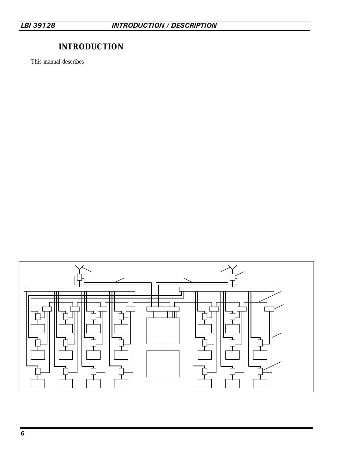
Figure 1 shows the locations of the PMU-related
components in a standard 20-channel EDACS installation
after the PMU option has been installed. Each standard
EDACS repeater cabinet includes the unidirectional power
sensors, power sensor cables, power sensor module, and
cabinet interconnect cable. The cable between the Site
Controller computer and the PMU, the cables between the
PMU and the Power Sensor interface module, and the Power
Sensor interface module all come with the PMU. The bidirectional (antenna) power sensor(s) are ordered separately.
If the PMU option is to be installed in an older EDACS
site, you may need some additional material to update or
adapt to the older equipment (see the Installation section in
this manual for details).
Xmtr
#12
Xmtr
#11
Xmtr
#10
Xmtr
#9
Xmtr
#8
Xmtr
#7
Antenna #1
Xmtr
#6
Xmtr
#5
Xmtr
#4
Antenna Power Sensor Cable
Interface Module
Xmtr
#3
Xmtr
#2
Xmtr
#1
Power
Monitor
Unit
Site
Controller
Computer
Antenna #2
Transmitter Combiner #2Transmitter Combiner #1
Xmtr
#15
Xmtr
#14
Xmtr
#13
Xmtr
#18
Xmtr
#17
Xmtr
#16
Bi-directional
Power
Sensor
Xmtr
#20
Xmtr
#19
Cabinet
Interconnect
Cable
Power Sensor
Interface
Module
Transmitter
Power Sensor
Cable
Unidirectional
Power
Sensor
Figure 1 - Location of PMU Components
6
Page 7

APPLICATION NOTES LBI-3912
8
APPLICATION NOTES
VAX SITE CONTROLLER COMPUTER
Make sure that the Site Controller computer, at the
location where this PMU is to be installed, is a VAX model
or a PDP model that has been upgraded to a VAX model. To
determine if a PDP model has been upgraded internally to a
VAX model, you must look inside the PDP system chassis
and see which cards are installed. PDP models that have
been upgraded to a VAX model will have their cards
arranged in the card cage as shown in Figure 2.
KA620-BA
MS630-BB
MRV11-D H3656-00
CQ1610#1
CQ1610#2
EMPTY
EMPTY
EMPTY
•
PMU Enable
(for each channel) if that channel number is to be
monitored by the PMU. This parameter is not
System Manager re-configurable and therefore all
equipped channels must be enabled. It is
recommended that all 20 channels be enabled
(equipped or not).
•
Power Monitor Unit
to “Off” (if you want the PMU option disabled) or
“On” (if you want the PMU option enabled). This
parameter is System Manager re-configurable, but
must be set to “On” if the site is being operated
without a System Manager. It is recommended that
this parameter be set to “On”, even if the site is
being operated with a System Manager.
•
PMU Model
8843” (PMU protocol set to 2400 Baud for Decibel
Products DB8843 based old PMU) or “New-8860”
(PMU protocol set to 9600 Baud for Decibel
Products DB8860 based new PMU). This
parameter is not System Manager re-configurable
and therefore must be set to “New-8860”.
- This parameter set (mask) defines
- This parameter can be set
- This parameter can be set to “Old-
Figure 2 - Card Layout for PDP Upgraded to VAX
APPLICATION SOFTWARE PROMS
The Site Controller computer’s Application Software
PROMs must be marked 344A3265Gx, where x = 6 or
higher. (Application Software PROMs with x = 5 or lower
will not work for the new PMU.) If new Application
Software PROMs are needed, they should be ordered when
ordering the new PMU.
PERSONALITY PROMS
The Site Controller computer’s Personality PROMs
must be replaced, even if the system currently has an old
PMU and a System Manager. New Personality PROMs
should be ordered when ordering the new PMU.
When ordering new Personality PROMs, you must give
the correct information for the following four PMU
parameters (don’t assume that the person taking the order
will know what you want, need, or the recommendations
given here):
•
PMU Power Levels
lower power level limit for all transmitters (one
limit is applied to all). This parameter is System
Manager re-configurable, but must be set to some
power level lower than rated power if the site is
being operated without a System Manager. It is
recommended that this parameter be set to 50% of
the rated power, even if the site is being operated
with a System Manager.
- This parameter defines the
NOTE
If this PMU option is being installed in the field,
these Personality PROMs must be changed, even
if the system currently has the old PMU option
and a System Manager.
7
Page 8

LBI-39128 INSTALLATION
INSTALLATION
SITE CONTROLLER HARDWARE
Verify that the Site Controller computer is a VAX
model, or a PDP model that has been upgraded to a VAX
model (see the VAX Site Controller heading in the
Applications Notes section). If you find that the Site
Controller computer is a PDP model, upgrade kits are
available through Ericsson Service P arts. Alternatively, the
PDP model may be replaced with the current 19A149302P9
VAX model.
SITE CONTROLLER SOFTWARE
The Site Controller computer contains a set of 14
Application Software PROMs and a set of two Personality
PROMs. Both sets are located on the PROM card. Access to
the PROM card in the latest VAX version of the Site
Controller computer is through the b ack using the following
procedure:
1. Turn off the Site Controller computer.
Access to the PROM card in previous VAX versions
and older PDP versions that were upgraded to a VAX
version is through the top using the following procedure:
1. Turn off the Site Controller computer.
2. Pull the Site Controller computer chassis all the
way forward on its slide-out track.
3. Pull up the top cover and the attached card cage.
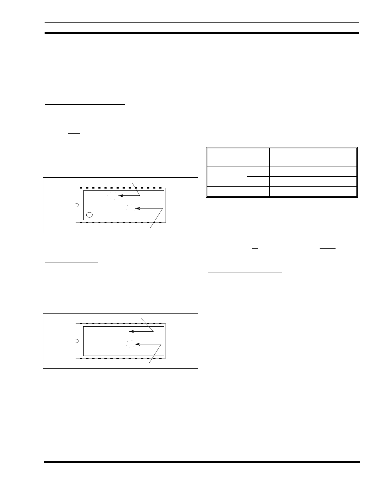
4. Remove the PROM Card (see Figure 5) by pulling
on the two tabs fastened to the front edge of the
card. (This is a three-handed operation - observe
standard handling practices for static sensitive
components.)
PROM Card
Figure 5 - Location of PROM Card in Older Computer
2. Loosen the two fastener screws holding the back
panel to the chassis (see Figure 3).
28293031
15
Fastener
Screws
27 26 25 24
20212223
19 18 17 16
14 13 12 11 10 9
2345678
1
0 SM
Figure 3 - Location of Fastener Screws on Computer
3. Rotate the back panel down and out of the way (be
careful not to damage the ribbon cables).
PROM Card
Figure 4 - Location of PROM Card in Computer
4. Remove the PROM Card (see Figure 4) by pulling
on the two tabs fastened to the front edge of the
card. (Observe standard handling practices for
static sensitive components.)
Personality
PROMs
13 14
01-02
01 02
09 10
11 12
Application
0605
0807
Software
PROMs
01-14
0201
03 04
Figure 6 - Location of PROMs on PROM Card
8
Page 9
INSTALLATION LBI-39128
The location of the Application Software and
Personality PROMs on the PROM card is shown in Figure
6. When replacing PROMs, be sure to get each new PROM
in the correct location, and with the notched end as shown.
Be especially careful of location numbers 01 and 02 since
these numbers are used for both sets of PROMs.
Application Software PROMs
Check the revision number marked on the Application
Software PROMs. Each of the 14 Application Software
PROMs must be marked 344A3265Gx, where x = 6 or
higher. (Application Software with x = 5 or lower will not
work for the new PMU option.) Figure 7 shows where to
find the software revision number and the PROM location
number on a typical Application Software PROM label.
Replace all 14 Application Software PROMs if required.
Software Revision
344A3265G6
VAX SITE CTRLR
EDACS
1994 BY ERICSSON GE
C
01
PROM Location
Figure 7 - Application Software PROM Label
Personality PROMs
Replace the two Personality PROMs, even if a PMU
was previously installed with this Site Controller computer.
Figure 8 shows a typical Personality PROM label. (See the
Application Notes section if you need to order new
Personality PROMs.)
Serial Number
SER#: 12345678
SITE CONTROLLER
EDACS
PERSONALITY
01
PROM Location
Figure 8 - Personality PROM Label
PMU HARDWARE
There are three procedures for the installation of the
PMU hardware. The procedure you should use will depend
upon whether or not the Site Controller cabinet presently
contains EDACS Interface Panels and/or an old PMU. The
EDACS Interface Panels are located in the back of the
cabinet, near the top. Each panel consists of a 5 1/4 inch X
19 inch frame containing one or more interface modules
(boards with connectors). Use Table 1 to select the right
PMU hardware installation procedure for your system.
Table 1 - Selection of Installation Procedure
INTERFACE
PANEL
Yes No A. Addition from No PMU
No Yes C. Adaptation from Old PMU
The table and the procedures assume that the equipment
that presently exists in the Site Controller cabinet is one of
the previous standard configurations. Regardless of which
procedure is used, it is very important to know exactly what
equipment presently exists, review what has to be done, and
be sure you have all the parts you will need before
the installation.
A. Addition from No PMU
Use this procedure only if your Site Controller cabinet
has EDACS Interface panels, but doesn’t have a PMU.
This procedure consists of adding the PMU, Power
Monitor interface module, cables between the PMU and the
Power Monitor interface module, cable between the PMU
and the Site Controller computer, and DC power wires to the
PMU, all in the Site Controller cabinet. It also consists of
adding the antenna power sensor(s) in the RF Equipment
cabinet(s), and the antenna power sensor cables between the
antenna power sensor(s) in the RF Equipment cabinet(s) and
the Power Monitor interface module in the Site Controller
cabinet.
OLD
PMU
HARDWARE INSTALLATION
PROCEDURE
Yes B. Upgrade from Old PMU
you sta rt
9
Page 10

LBI-39128 INSTALLATION
Parts Required
Before you start this procedure, be sure you have all the
parts on hand. The parts for this procedure are shown in
Table 2.
Table 2 - Parts for Addition from No PMU
QTY PART # DESCRIPTION
1 19D903880P100
or
19D903880P101
1 350A1380P1 Decibel Products DB8860-
1 188D6466P1 Cable - PMU to Power
5 188D6466P2 Cable - PMU to Power
1 19C852632G1 Power Sensor interface
1 19C852677P1 Cable - Power Sensor
1 or219C336861P3
or
19C336861P4
Procedure
The following steps involve equipment in the Site
Controller cabinet, except as noted:
Cable - DILOG Panel to
PMU
Cable - Site Controller
computer to PMU
based PMU Unit
Sensor interface module
Sensor interface module
module
interface module to Antenna
power sensor(s)
Antenna power sensor (450
- 1000 MHz)
Antenna power sensor (66 -
325 MHz)
the four thread forming screws provided with it. (You
will need a T15 Torx-head screwdriver.) If an old
Power Sensor interface module is mounted there,
replace it with the new 19C852632G1 interface module.
This interface module contains two 19C852379G1
Channel Termination Boards, each containing 12
shorting jumpers. The boa rd plugged into J1 is used to
short any unused power sensor circuit for Transmitter
channels #1 through #12. T he board plugged into J2 is
used to short any unused power sensor circuit for
Transmitter channels #11 through #20.
6. Remove the 19C852379G1 Channel Termination Board
from J1 on the Power Sensor interface module (installed
in step 5), and connect a 25-pair cabinet interconnect
cable in its place. Connect the other end of the 25-pair
cabinet interconnect cable to J14 or J15 on the Power
Sensor interface module in the EDACS Repeater
cabinet containing the transmitter for channel #1). If the
two cabinets are next to each other in the same row, use
a 5-ft 19D903880P120 cable. If the two cabinets are
across from each other in different rows, use a 15-ft
19D903880P121 cable.
7. Starting with the cabinet containing the transmitter for
channel #1, follow the daisy chain of 25-pair cabinet
interconnect cables connected to J14 and J15 on the
Power Sensor interface module in each EDACS
Repeater cabinet until an empty J14 or J15 connector is
found. Plug the 19C852379G1 Channel Termination
Board (removed in the previous step) into this empty
connector.
8. Remove the shorting jumper for each transmitter
channel # equipped with a power sensor (P#
corresponds to transmitter channel #).
1. Turn off the main 12V power supply for the cabinet.
2. Replace the 5 1/4 inch blank panel just above the
Downlink GETC (called Trunking Card in some older
installations) with the PMU. There will be a half rack
unit space (7/8 inch) both above and below the PMU.
3. Connect the #18 red wire from the terminal on the back
of the PMU labeled “+”, to TB10-7 on the back of the
Downlink GETC shelf.
4. Connect the #18 black wire from the terminal on the
back of the PMU labeled “–”, to TB10-6 on the back of
the Downlink GETC shelf.
5. Mount the new 19C852632G1 Power Sensor interface
module on the left-hand end of the upper EDACS
Interface Panel in the upper rear of the cabinet, using
10
Note that there is a shorting jumper for transmitter
channels #11 and #12 on each of the 19C852379G1
Channel Termination Boards. Therefore, if transmitter
channel #11 or #12 is equipped with a power sensor, a
jumper must be removed from each of the two channel
termination boards.
9. If the system does not have any additional EDACS
Repeater cabinets not included in the daisy chain in the
previous step, go to step 11.
If the system has additional EDACS Repeater cabinets
not included in the daisy chain in the previous step,
remove the 19C852379G1 Channel Termination Board
from J2 on the Power Sensor interface module (installed
in step 5), and connect a 25-pair cabinet interconnect
cable in its place. Connect the other end of the 25-pair
cabinet interconnect cable to J14 or J15 on the Power
Page 11
INSTALLATION LBI-39128
Sensor interface module in the EDACS Repeater
cabinet containing the transmitter for channel #11 or
#13). If the two cabinets are next to each other in the
same row, use a 5-ft 19D903880P120 cable. If the two
cabinets are across from each other in different rows,
use a 15-ft 19D903880P121 cable.
10. Starting with the cabinet containing the transmitter for
channel #11 or #13, follow the daisy chain of 25-pair
cabinet interconnect cables connected to J14 and J15 on
the Power Sensor interface module in each EDACS
Repeater cabinet until an empty J14 or J15 connector is
found. Plug the 19C852379G1 Channel Termination
Board (removed in the previous step) into this empty
connector.
11. Remove a shorting jumper in the 19C852379G1
Channel Termination Board for each transmitter
channel # equipped with a power sensor (P# plus 12
corresponds to transmitter channel #). Note that the P#
corresponds to a different transmitter channel # in this
case.
Note that there is a shorting jumper for transmitter
channels #11 and #12 on each of the 19C852379G1
Channel Termination Boards. Therefore, if transmitter
channel #11 or #12 is equipped with a power sensor, a
jumper must be removed from each of the two channel
termination boards.
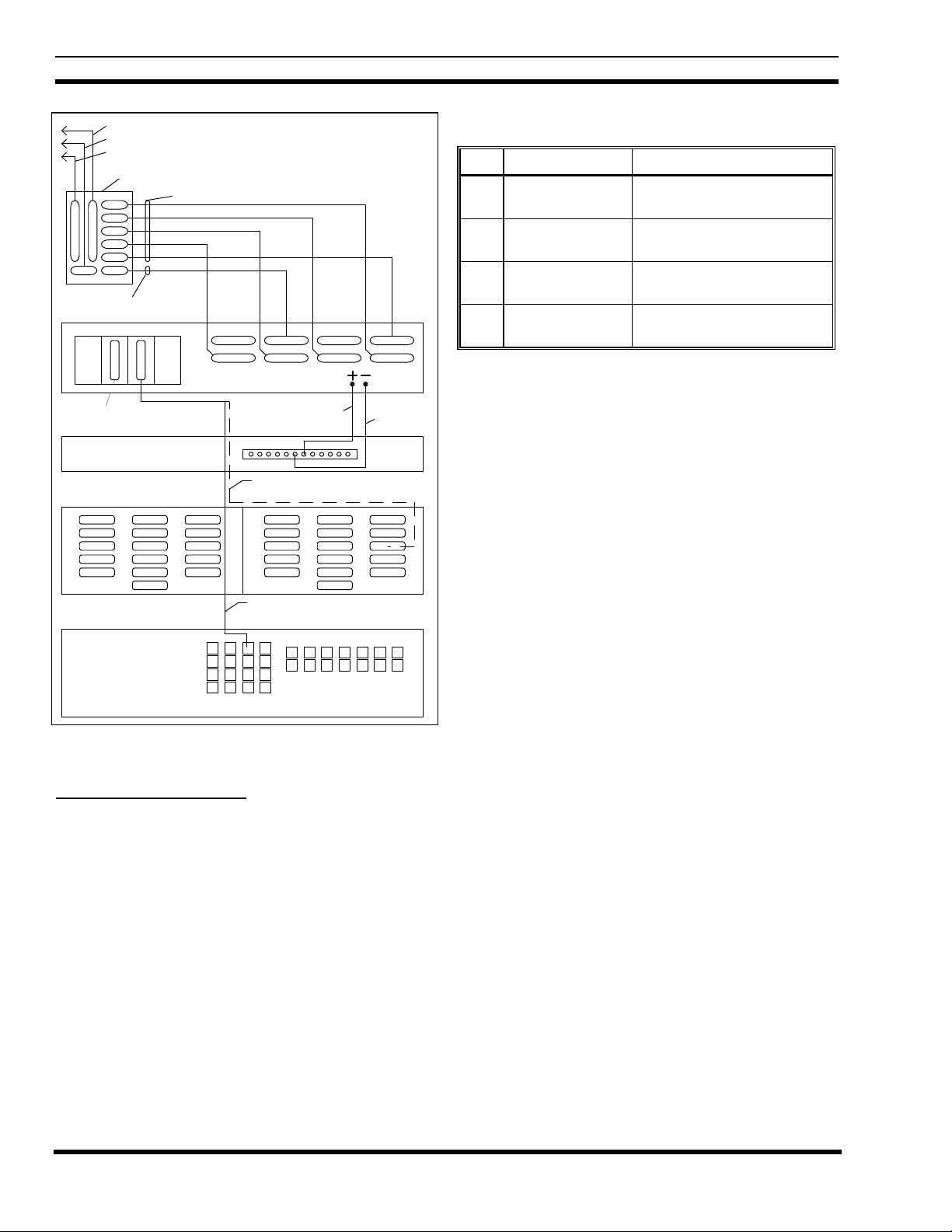
12. Connect the five new 188D6466P2 cables from J3
through J7 on the Power Sensor interface module in the
upper EDACS Interface Panel, to Port 1 through Port 5
respectively on the back of the PMU.
13. Connect the new 188D6466P1 cable from J8 on the
Power Sensor interface module in the upper EDACS
Interface Panel, to PORT 7 on the back of the PMU.
If the Site Controller computer does not have modular
RJ11-8 connectors on its back panel, connect the new
19D903880P100 cable from the right-hand VDT
Interface on the back of the PMU to connector #13 on
the right-hand (B) DILOG panel (above the Site
Controller computer).
15. Install the 19C336861P3 or P4 antenna power sensor(s)
at the output of the transmitter combiner(s) in the RF
Equipment cabinet(s).
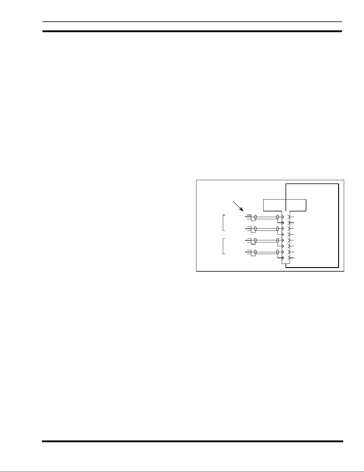
16. Install the 19C852677P1 antenna power sensor cable
from J9 on the Power Sensor interface module in the
Site Controller cabinet, to the antenna power sensor(s)
in the RF equipment cabinet(s) as shown in Figure 9. If
the system has only one antenna, tack solder a jumper
(tip to shield) on each of the unused phono plugs to
short the forward and reflected power sensor circuits for
antenna #2.
19C852632G1
J9
DB-9 (F)
1
6
2
7
3
8
4
9
High
Ground
High
Ground
High
Ground
High
Ground
POWER SENSOR
Antenna Power Sensor Cable
Antenna #1
Antenna #2
to Interface Module
Antenna Power Sensors
Forward
Reflected
Forward
Reflected
DB-9 ( M)
Figure 9 - Antenna Power Sensor Connections
17. Double check the installation using the interconnection
diagram shown in Figure 10.
14. If the Site Controller computer has modular RJ11-8
connectors on its back panel, connect the new
19D903880P101 cable from the right-hand VDT
Interface on the back of the PMU, to Port 29 on the
back of the Site Controller computer.
18. Set the power switch on the back of the PMU to the
“Off” position.
19. Turn on the main 12V power supply for the cabinet.
11
Page 12
LBI-39128 INSTALLATION
Daisy Chain Cable to Power Sensors for Transmitter Channels 11 - 20
Antenna Power Sensor Cable to Power Sensors for Antennas 1 & 2
Daisy Chain Cable to Power Sensors for Transmitter Channels 1 - 12
19C852632G1 POWER SENSOR INTERFACE MODULE
J3
J4
J1 J2
J5
J6
J7
J8J9
188D6466P1 Cable
VDT Interfaces
Programming
Terminal
Connection
DOWNLINK GETC
(TRUNKING CARD)
0511 0511AB
188D6466P2 Cables (5 Each)
PORT 8 PORT 6
POWER MONITOR UNIT
PORT 7 PORT 5
112
6
Use 19D903880P100 Cable If
Connecting to DILOG Panel
#18 Red
7
PORT 1PORT 4 PORT 2PORT 3
#18 Black
13B
Table 3 - Parts for Upgrade from Old PMU
QTY PART # DESCRIPTION
1 350A1380P1 Decibel Products DB8860-
based PMU Unit
1 188D6466P1 Cable - PMU to Power
Sensor interface module
5 188D6466P2 Cable - PMU to Power
Sensor interface module
1 19C852632G1 Power Sensor interface
module
Procedure
The following steps involve equipment in the Site
Controller cabinet only:
1. Turn off the main 12V power supply for the cabinet.
2. Mark “+” on the wire going to the screw terminal
marked “+” on the back of the old PMU. Then
disconnect this wire at the PMU end.
DILOG DILOG
Use 19D903880P101 Cable If
Connecting to Site Controller Computer
Port 29
SITE CONTROLLER
COMPUTER
Figure 10 - Connections for Addition from No PMU
B. Upgrade from Old PMU
Use this procedure only if your Site Controller cabinet
has EDACS Interface panels and an old PMU.
This procedure consists of upgrading the Site Controller
by replacing the old PMU, replacing the old Power Sensor
interface module, and replacing the cables between them.
Parts Required
Before you start this procedure, be sure you have all the
parts on hand. The parts for this procedure are shown in
Table 3.
3. Mark “–” on the wire going to the screw terminal
marked “–” on the back of the old PMU. Then
disconnect this wire at the PMU end.
4. Mark “RS-232” on the cable going to the DB-25
connector marked “RS-232” on the back of the old
PMU. Then disconnect this cable at the PMU end.
5. Disconnect any cables going to the connectors marked
“Antennas 1-4”, “Transmitters 1-9”, “Transmitters 1018”, and “Transmitters 19-20” on the back of the old
PMU. (There is no need to label these cables since they
will not be used with the new PMU.)
6. Replace the old PMU with the new PMU. There will be
a half rack unit space (7/8 inch) both above and below
the new PMU.
7. Connect the existing wire labeled “+” in step 2 to the
terminal labeled “+” on the back of the new PMU.
8. Connect the existing wire labeled “–” in step 3 to the
terminal labeled “–” on the back of the new PMU.
9. Connect the existing cable labeled “RS232” in step 4 to
the right-hand VDT interface on the back of the new
PMU (see Figure 7).
12
10. Find the Power Sensor interface module mounted in the
left end of the upper EDACS Interface Panel in the
upper rear of the cabinet. If a cable is connected to the
Page 13

INSTALLATION LBI-39128
Power Sensor interface module connector marked “J1”,
label the cable “J1” and disconnect it from the Power
Sensor interface module.
11. If a cable (or an existing 19C852379G1 Channel
Termination Board) is connected to the Power Sensor
interface module connector marked “J2”, label the cable
(or board) “J2” and disconnect it at the Power Sensor
interface module.
12. Find the cables (or group of cables) connected to the
Power Sensor interface module connectors marked “J6”
and “J7”, determine which cable (or group of cables)
goes to some point outside the cabinet, label this cable
(or group of cables) “J9” (the connector number on the
new Power Sensor interface module is different), and
disconnect this cable (or group of cables) at the Power
Sensor interface module.
13. Remove the old 19C852213G1 Power Sensor interface
module and all cables still connected to it (all cables
still connected to it should have been disconnected at
their other end in step #5).
14. Mount the new 19C852632G1 Power Sensor interface
module in the space vacated by the old module.
15. Connect the existing cables (or board) labeled “J1”,
“J2”, and “J9” in steps 10-12 to the connectors marked
“J1”, “J2”, and “J9” respectively on the new Power
Sensor interface module.
16. Connect the 5 new 188D6466P2 cables from J3 through
J7 on the new Power Sensor interface module to Port 1
through Port 5, respectively, on the back of the new
PMU.
17. Connect the new 188D6466P1 cable from J8 on the
new Power Sensor interface module to Port 7 on the
back of the new PMU (skip Port 6).
18. Double check the installation using the interconnection
diagram shown in Figure 11.
Daisy Chain Cable to Power Sensors for Transmitter Channels 11 - 20
Antenna Power Sensor Cable to Power Sensors for Antennas 1 & 2
Daisy Chain Cable to Power Sensors for Transmitter Channels 1 - 12
19C852632G1 POWER SENSOR INTERFACE MODULE
J3
J4
J1 J2
J5
J6
J7
J8J9
188D6466P1 Cable
VDT Interfaces
Programming
Terminal
Connection
DOWNLINK GETC
188D6466P2 Cables (5 Each)
PORT 8 PORT 6
POWER MONITOR UNIT
Existing Cable To Site Controller Computer
PORT 7 PORT 5
#18 Red
112
7
6
PORT 1PORT 4 PORT 2PORT 3
#18 Black
Figure 11 - Connections for Upgrade from Old PMU
This procedure consists of replacing the old PMU with
the new PMU, adding an adapter cable between the existing
transmitter power sensor cables and the new PMU, and
adding an adapter cable between the existing antenna power
sensor cable and the new PMU. The existing RS232 data
link to the Site Controller computer and the two DC power
wires can be re-connected directly to the new PMU. This
procedure upgrades the system to the extent that it adds the
new PMU, but uses adapter cables instead of upgrading to
the EDACS Interface Panel configuration.
Parts Required
Before you start this procedure, be sure you have all the
parts on hand. The parts for this procedure are shown in
Table 4.
Table 4 - Parts for Adaptation from Old PMU
19. Set the power switch on the back of the PMU to the
“Off” position.
20. Turn on the main 12V power supply for the cabinet.
C. Adaptation from Old PMU
Use this procedure only if your Site Controller cabinet
doesn’t have EDACS Interface panels, but does have an old
PMU.
QTY PART # DESCRIPTION
1 350A1380P1 Decibel Products DB8860-
based PMU Unit
1 188D6451P1 Adapter Cable - Transmitter
power sensor circuits
1 188D6496P1 Adapter Cable - Antenna
power sensor circuits
13
Page 14

LBI-39128 INSTALLATION
Procedure
The following steps involve equipment in the Site
Controller cabinet, except as noted:
1. Mark the cables and wires going to the old PMU as
follows:
• Mark “Antennas 1-4” on the cable going to the DB-
15 connector on the back of old PMU marked
“Antennas 1-4”.
• Mark “Transmitters 1-9” on the cable going to the
DB-37 connector on the back of the old PMU
marked “Transmitters 1-9”.
• Mark “Transmitters 10-18” on the cable going to
the DB-37 connector on the back of the old PMU
marked “Transmitters 10-18”.
• Mark “Transmitters 19-20” on the cable going to
the DB-25 connector on the back of the old PMU
marked “Transmitters 19-20”.
• Mark “RS-232” on the cable going to the DB-25
connector on the back of the old PMU marked
“RS-232”.
• Mark “+” on the wire going to the screw terminal
marked “+”.
• Mark “–” on the wire going to the screw terminal
marked “–”.
2. Turn off the main 12V power supply for the cabinet.
3. Disconnect the cables and wires from the old PMU.
4. Replace the old PMU with the new PMU. There will be
a half rack unit space (7/8 inch) both above and below
the PMU.
5. Connect the 188D6451P1 adapter cable as follows:
• Connect the two DB-37 connectors on the adapter
cable marked “P2” and “P3” to the existing cables
(disconnected from the old PMU) marked
“Transmitters 1-9” and “Transmitters 10-18”
respectively.
• Connect the five DB-25 connectors on the other
end of the adapter cable marked “P5”, “P6”, “P7”,
“P8”, and “P9” to Port 1 through Port 5
respectively on the back of the new PMU.
6. Connect the 188D6496P1 adapter cable as follows:
• Connect the DB-15 connector on the adapter cable
marked “P2” to the existing cable (disconnected
from the old PMU) marked “Antennas 1-4”.
• Connect the DB-25 connector on the adapter cable
marked “P3” to Port 7 on the back of the new
PMU.
7. Connect the existing cable (disconnected from the old
PMU) marked “RS-232” to the right VDT Interface
connector on the back of the new PMU.
8. Connect the existing wires (disconnected from the old
PMU) marked “+” and “–” to the screw terminals on the
back of the new PMU marked “+” and “–” respectively.
9. Double check the installation using the interconnection
diagram shown in Figure 12.
Transmitters 1-9
Transmitters 10-18
Transmitters 19-20
188D6451P1 Adapter Cable
188D6496P1 Adapter Cable
Antennas 1-4
VDT Interfaces
Programming
Terminal
Connection
P2
P3
P4
P2
POWER MONITOR UNIT
P3
PORT 7 PORT 5PORT 8 PORT 6
P5P6P7P8 P9
PORT 1PORT 4 PORT 2PORT 3
_
+
RS-232
Figure 12 - Connections for Adaptation from Old PMU
10. Set the power switch on the back of the PMU to the
“Off” position.
11. Turn on the main 12V power supply for the cabinet.
INITIAL POWER-UP
• Connect the single DB-25 connector on one end of
the adapter cable marked “P4” to the existing cable
(disconnected from the old PMU) marked
“Transmitters 19-20”.
14
After the PMU equipment has been mounted and
checked, you are ready for the initial power-up of the PMU.
1. Temporarily disconnect the data link cable to the Site
Controller computer from the right-hand VDT Interface
Page 15

INSTALLATION LBI-39128
on the back of the PMU (this cable will be re-connected
later in the installation).
2. Switch the On/Off switch on the back of the PMU to the
“On” position.
3. Verify that the “PWR” indicator on the front panel of
the PMU stays on continuously.
4. Verify that the three other indicators on the front panel
of the PMU are flashing in a repeating sequence. The
“MUX” indicator should flash once every 250
milliseconds; first by itself, next with the “DATA”
indicator, and then with the “ALARM” indicator.
PMU PROGRAMMING
The PMU’s operational program will use the factory
default values for its operational parameters unless reconfigured by the user. The user-configurable parameters
may be re-configured through the use of an RS232 CRT
terminal (or PC with terminal emulation software) connected
to the PMU.
CAUTION
(or PC COM Port)
11
Tx Data
Rx Data
33
4
CTS CTS
6
Ground
7
Null Modem Cable
Figure 13 - DB-25 Terminal Connections
(or PC COM Port)
11
Rx Data
Tx Data
33
4
DTR
Ground
6
7
RTS
8
CTS
Null Modem Cable
PMURS232 CRT Terminal
Left VDT Interface
DB-25 (F)DB-25 (M) DB-25 (M)DB-25 (F)
22
Tx Data
Rx Data
RTSRTS
4
55
6
DSRDSR
7
Ground
2020
DTRDTR
PMURS232 CRT Terminal
Left VDT Interface
DB-25 (F)DB-9 (M) DB-25 (M)DB-9 (F)
22
Tx Data
Rx Data
RTS
4
55
CTS
6
DSRDSR
7
Ground
209
DTR
Changing parameters not covered in this
manual may lead to unsatisfactory operation of
the PMU option.
Terminal Setup
The following initial steps are required to set up the
terminal and access the PMU.
1. Connect the RS232 CRT terminal to the left-hand VDT
Interface connector on the back of the PMU (see Figure
12). (DO NOT plug into the front of the PMU.) If the
RS232 CRT terminal has a male DB-25 port, connect
per Figure 13. If the terminal has a male DB-9 port,
connect per Figure 14.
CAUTION
DO NOT plug the RS232 CRT terminal in to t he
front panel of the PMU (damage to terminal
may result). This connnector is for another
device in another application.
Figure 14 - DB-9 Terminal Connections
2. Turn the terminal on and set the communications
protocol per Table 5.
Table 5 - Terminal Communications Protocol
PARAMETER VALUE
Baud Rate 9600 BPS
Data Bits 8
Parity None
Stop Bits 1
3. Press the Enter key one or more times until the
“Disconnected - Hit Any Key To Connect” prompt
appears on the terminal:
Software Initialization
Before you attempt to program any PMU parameters,
all parameters should be returned to the factory default
values. The following procedure is used to initialize the
PMU with its factory defaults:
15
Page 16

LBI-39128 INSTALLATION
4. Type 8860 and press the Enter key. The Operation
Select Menu should then appear on the terminal as
shown in Figure 15 (revision # and date may be
different). If the PMU does not respond to this entry,
the password may have been re-configured from its
factory default value. See the Erase All Programming
heading in the Maintenance section for the procedure to
return all parameters to the factory default values,
including returning the password to 8860.
5. With the Operational Select Menu shown on the
terminal, type 4 (for item #4 - Setup) and press the
Enter key. The Setup Selection Menu should then
appear on the terminal as shown in Figure 16.
SENTRY 8860 COPYRIGHT 1987-1994 DECIBEL PRODUCTS
PATENT 4,823,280
OPERATION SELECT MENU SENTRY PMU REV 8.6 12/07/94
1. DISCONNECT
2. REPORTS
3. MANUAL CONTROL
4. SETUP
5. HARDWARE STATUS
6. SOFTWARE STATUS
7. RESET ***WARNING - FOR EMERGENCY ONLY***
ENTER SELECTION:
6. With the Setup Selection Menu shown on the terminal,
type 10 (for item #10 - Erase All Programming) and
press the Enter key.
7. At the “Enter Y to Continue, Any Other Character to
Abort:” prompt (after the warning message), type Y and
press the Enter key.
8. At the “Enter Site Password” prompt, type 8860 and
press the Enter key.
9. At the “Enter Site ID” prompt, type 1234 and press the
Enter key. You will be given a 4-second countdown and
then a flashing “Sentry Initialized” message.
10. Finally the Setup Selection Menu should appear on the
terminal.
Figure 15 - Operation Select Menu (Main Menu)
SETUP SELECTION MENU
1. RETURN TO OPERATION SELECT MENU
2. SITE DATA #1
3. SITE DATA #2
4. ANALOG INPUT CHANNEL
5. DIGITAL INPUT CHANNEL
6. ANALOG PSEUDO CHANNEL
7. DIGITAL PSEUDO CHANNEL
8. RELAY OUTPUTS
9. INPUT CONVERSION TABLE
10. ERASE ALL PROGRAMMING
11. db TEST CONFIGURATION
12. db TOWER LIGHTS CONFIGURATION
ENTER SELECTION: _
Figure 16 - Setup Selection Menu
16
Page 17

INSTALLATION LBI-39128
Time/Date/Password
The following steps to set the time, date, and password
are optional and have no affect on the performance of the
PMU:
11. With the Setup Selection Menu shown on the terminal,
type 2 (for item #2 - Site Data #1) and press the Enter
key. The Site Data #1 screen should then appear o n the
terminal as shown in Figure 17.
12. With the Site Data #1 screen shown on the terminal,
type 1 (for item #1 - Time) and press the Enter key.
13. At the “Enter New Data:” prompt, type up to 4
numerical characters (do not type the colon, am, or pm)
and press the Enter key. Use the following samples as a
guide:
Type 1 or 01 to get 1:00 am.
Type 13 to get 1:00 pm.
Type 130 to get 1:30 am.
Type 1330 to get 1:30 pm.
SITE DATA #1
14. With the Site Data #1 screen shown on the terminal,
type 2 (for item #2 - Date) and press the Enter key.
15. At the “Enter New Data:” prompt, type 4 numerical
characters (do not type the / ) and press the Enter key.
The first 2 numbers are for the month; the second 2
numbers are for the day of the month. Use the following
samples as a guide:
Type 1 or 01 to get 1/00.
Type 12 or 120 to get 12/00.
Type 0120 to get 1/20.
Type 1201 to get 12/01.
16. With the Site Data #1 screen shown on the terminal,
type 3 (for item #3 - Year) and press the Enter key.
17. At the “Enter New Data:” prompt, type all 4 characters
for the year and press the Enter key.
18. With the Site Data #1 screen shown on the terminal,
type 6 (for item #6 - Password) and press the Enter key.
1. TIME = 0:01 am
2. DATE = 1/01
3. YEAR = 1994
4. SITE NAME = NOT PROGRAMMED
5. SITE ID = 1234
6. PASSWORD = 8860
7. REPORT TIME = 8. REPORT TIME =
9. REPORT TIME = 10. REPORT TIME =
11. PH #1 PRI=H 12. PH #1 ALT=
13. RETRY INTERVAL #1 (min)= 10
14. PH #2 PRI= 15. PH #2 ALT=
13. RETRY INTERVAL #2 (min)= 10
14. PH #3 PRI= 15. PH #3 ALT=
13. RETRY INTERVAL #3 (min)= 10
14. PH #4 PRI= 15. PH #4 ALT=
13. RETRY INTERVAL #4 (min)= 10
ENTER ITEM NUMBER TO CHANGE,
"H" FOR HELP MENU, "A" TO ABORT,
OR "E" TO END PROGRAMMING THIS CHANNEL:
Figure 17 - Site Data #1 Screen
17
Page 18

LBI-39128 INSTALLATION
19. At the “Enter New Data:” prompt, type up to 4
characters for the password and press the Enter key.
Check the password shown on the Site Data #1 screen
to be absolutely sure it is what you expected and want.
If not, return to step #8 and redo the password. If you
try to enter more than 4 characters, only the first 4 will
be used. After you are satisfied with the password, go
on to the next step.
20. Type E (to end programming this screen) and press the
Enter key. The Setup Selection Menu should then
appear on the terminal.
Antenna Mapping
Antenna Mapping tells the PMU which antenna is used
by each transmitter. The factory defaults have AI025
(antenna #1) mapped for transmitters #1 through #10 and
AI027 (antenna #2) mapped for transmitters #11 through
#20. If any transmitter is connected to an antenna other than
described by these default values, the Antenna Channel
parameter must be re-configured.
The following steps must be repeated for each
transmitter that is connected to a different antenna # than
described by the PMU’s factory defaults. Those transmitters
for which the PMU’s factory defaults are correct, may be
skipped. Transmitters may be configured in any order, but
starting with the lowest transmitter # and working your way
up will probably be the easiest way to keep track of which
ones have been done.
22. At the “Enter Channel Number” prompt, type the
channel number of the transmitter and press the Enter
key. The Analog Input Channel screen for that channel
should then appear on the terminal (see Figure 18). (If
item #10 - Channel Enable Method = 5, item #11 will
not be present.)
23. With the Analog Input Channel screen shown on the
terminal, type 1 (for item #1 - Channel Type) and press
the Enter key.
24. At the “Enter New Data” prompt, type 3 and press the
Enter key. The screen will be re-written to add item #11
(or #12) - Antenna Channel (see Figure 19).
25. Type 11 or 12 (whichever corresponds to the Antenna
Channel) and press the Enter key.
26. At the “Enter New Data” prompt, type AI025 for
antenna #1 or AI027 for antenna #2, and press the Enter
key. The screen will be re-written to show the new
value.
27. Type E (to End programming this channel) and press
the Enter key. The Setup Selection Menu should then
appear on the terminal.
This completes the configuration of the Antenna
Channel parameter for the selected transmitter. If this
parameter needs to be changed for another transmitter,
return to step 21. When this parameter is satisfactory for all
transmitters, go on to step 28.
21. With the Setup Selection Menu shown on the terminal,
type 4 (for item #4 - Analog Input Channel) and press
the Enter key.
ANALOG INPUT CHANNEL 1
1. CHANNEL TYPE (0-13) = 0
2. DESCRIPTION = TX01
3. UNIT ID = AI01
4. MEASUREMENT UNITS = Watts
5. ALARM DELAY (1/4 sec) = 3
6. LOWER ALARM LIMIT = 0.0
7. UPPER ALARM LIMIT = 125.0
8. ALARM REPORT TYPES (1,2,3,4) =
9. ALARM RELAY NUMBER = 0
10. CHANNEL ENABLE METHOD (0-5) = 0
11. CHANNEL ENABLE THRESHOLD = 0.0
ENTER ITEM NUMBER TO CHANGE,
"H" FOR HELP MENU, "A" TO ABORT,
OR "E" TO END PROGRAMMING THIS CHANNEL:
Figure 18 - Analog Input Channel Screen
18
Page 19

INSTALLATION LBI-39128
ANALOG INPUT CHANNEL 1
1. CHANNEL TYPE (0-13) = 3
2. DESCRIPTION = TX01
3. UNIT ID = AI01
4. MEASUREMENT UNITS = Watts
5. ALARM DELAY (1/4 sec) = 3
6. LOWER ALARM LIMIT = 0.0
7. UPPER ALARM LIMIT = 125.0
8. ALARM REPORT TYPES (1,2,3,4) =
9. ALARM RELAY NUMBER = 0
10. CHANNEL ENABLE METHOD (0-5) = 0
11. CHANNEL ENABLE THRESHOLD = 0.0
12. ANTENNA CHANNEL = AI025
ENTER ITEM NUMBER TO CHANGE,
"H" FOR HELP MENU, "A" TO ABORT,
OR "E" TO END PROGRAMMING THIS CHANNEL: _
Figure 19 - Analog Input Channel Screen Showing Antenna Channel Parameter
28. With the Setup Selection Menu shown on the terminal,
type 1 (for item #1 - Return To Operation Select Menu)
and press the Enter key.
29. The Operation Select Menu should then be shown on
the terminal. Type 1 (for item #1 - Disconnect) and
press the Enter key.
Calibration Screw
30. The “Disconnected - Hit Any Key To Connect” prompt
should then appear on the terminal.
POWER SENSOR CALIBRATION
The power sensor provides a DC voltage output
representing the power through it. This calibration method
uses an in-line wattmeter to read the power going through
the power sensor, a DC voltmeter to measure the DC voltage
out of the power sensor, and a conversion table to simulate
the PMU’s calculation of power from this DC voltage. This
DC voltage is then adjusted (using the 20-turn p otentio meter
mounted in the power sensor) until the power read from the
conversion table agrees with the power read on the power
meter.
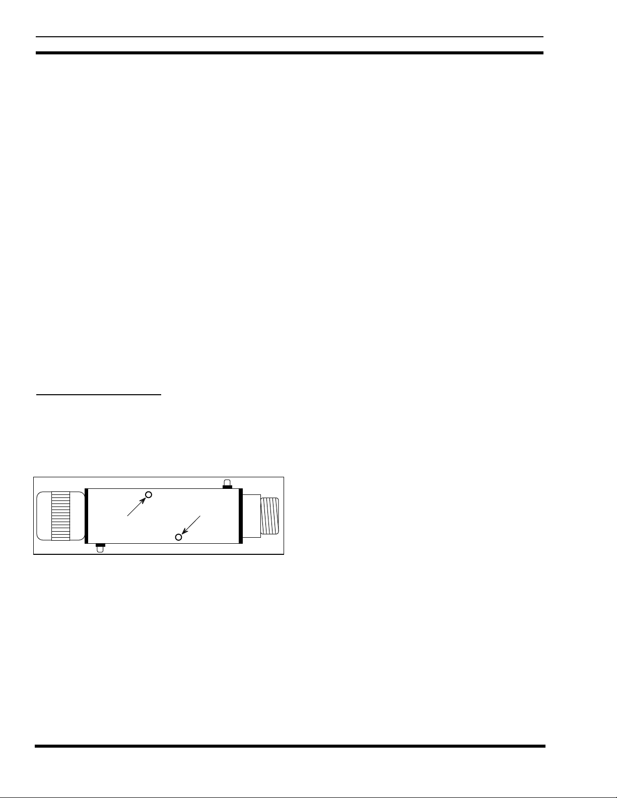
Unidirectional Power Sensors
Use the following procedure to calibrate the
unidirectional power sensors used at the output of each
transmitter. Start with the transmitter for channel #1. The
location of the calibration screw is shown in Figure 20.
Figure 20 - Unidirectional Power Sensor Calibration Screw
1. Turn off the 12V station power supply for the
transmitter.
2. Disconnect the coax (from the power sensor to the
combiner) at the power sensor end, and insert an in-line
wattmeter (make sure the wattmeter is rated high
enough to handle the power from the transmitter).
3. Disconnect the power sensor cable from the phono
connector on the power sensor, and attach the DC
voltmeter in its place (center pin is positive). (An
alternate method is to disconnect the power sensor cable
at the PMU - see interconnection diagram at end of
manual - and attach the DC voltmeter to the end of the
cable.)
4. Turn on the 12V station power supply for the
transmitter.
5. Manually key the transmitter using the switch marked
“REM KEY”, or press and hold the PTT switch on a
hand-held microphone plugged into the transmitter.
6. Measure the DC voltage on the meter, look up this
voltage in Table 6 (V in volts) to get the correspond ing
19
Page 20
LBI-39128 INSTALLATION
power (P in watts), and compare with the actual power
measurement on the power meter. Because the table
does not contain all values of V and P, you may need to
interpolate to get the values you need.
7. Turn the calibration screw (clockwise if the measured
power is lower than the power from the table) and
repeat steps 6 and 7 until the measured power is the
same as the power from the table.
8. Turn off the 12V station power supply for the
transmitter.
9. Disconnect the DC voltmeter from the phono connector
on the power sensor, and re-connect the power sensor
cable in its place.
10. Remove the wattmeter from between the power sensor
and the coax to the combiner, and re-connect the coax
to the power sensor.
11. Turn on the 12V station power supply for the
transmitter.
12. Repeat steps 1 through 11 for the next transmitter until
each transmitter has had its power sensor calibrated.
Bi-directional Power Sensors
Use the following procedure to calibrate the bi-
directional power sensors used at the output of each
combiner. Start with the combiner that feeds antenna #1.
The locations of the calibration screws are shown in Figure
21.
Reflected Power
Calibration Screw
Calibration Screw
Forward Power
Forward Power
Reflected Power
Figure 21 - Bi-directional Power Sensor Calibration Screws
1. Disconnect the coax (from the power sensor to the
antenna) at the power sensor end, and insert an in-line
wattmeter set to measure forward power (make sure the
wattmeter is rated high enough to handle the power
from all the transmitters feeding the combiner).
2. Disconnect the power sensor cable from the phono
connector for the forward power on the power sensor,
and attach the DC voltmeter in its place (center pin is
positive). (An alternate method is to disconnect the
power sensor cable at the PMU - see interconnection
diagram at end of manual - and attach the DC voltmeter
to the end of the cable.)
3. Manually key the transmitter using the switch marked
“REM KEY”, or press and hold the PTT switch on a
hand-held microphone plugged into the transmitter.
4. Measure the DC voltage on the meter, look up this
voltage in Table 6 (V in volts) to get the equivalent
power calculation (P in watts), and compare with the
actual power measurement on the power meter.
5. Turn the calibration screw (clockwise if the measured
power is lower than the power from the table) and
repeat steps 4 and 5 until the measured power is the
same as the power from the table.
6. Disconnect the DC voltmeter from the phono connector
on the power sensor, and re-connect the power sensor
cable in its place.
7. Set the in-line wattmeter to measure reflected power.
8. Disconnect the power sensor cable from the phono
connector for the forward power on the power sensor,
and attach the DC voltmeter in its place (center pin is
positive).
9. Manually key the transmitter using the switch marked
“REM KEY”, or press and hold the PTT switch on a
hand-held microphone plugged into the transmitter.
10. Measure the DC voltage on the meter, look up this
voltage in Table 6 (V in volts) to get the equivalent
power calculation (P in watts), and compare with the
actual power measurement on the power meter.
11. Turn the calibration screw (clockwise if the measured
power is lower than the power from the table) and
repeat steps 10 and 11 until the measured p ower is the
same as the power from the table.
12. Disconnect the DC voltmeter from the phono connector
on the power sensor, and re-connect the power sensor
cable in its place.
13. Remove the wattmeter from between the power sensor
and the coax to the combiner, and re-connect the coax
to the power sensor.
14. Repeat ste ps 1 through 13 for the other co mbiner (if two
transmit antennas are used).
20
Page 21

INSTALLATION LBI-39128
Table 6 - Power Sensor Voltage-to-Power Conversion Table
VP VP VP VP VP VP VP VP
0.00 0.0 0.62 25.5 1.25 80.6 1.87 164.4 2.50 276.7 3.13 417.2 3.76 585.9 4.38 782.7
0.01 0.6 0.64 26.8 1.27 82.8 1.89 167.5 2.52 280.6 3.15 422.0 3.77 591.6 4.40 789.3
0.03 1.0 0.66 28.1 1.28 85.0 1.91 170.6 2.54 284.6 3.17 426.9 3.79 597.4 4.42 795.9
0.05 1.4 0.68 29.5 1.30 87.2 1.93 173.7 2.56 288.6 3.19 431.8 3.81 603.1 4.44 802.5
0.07 1.8 0.70 30.8 1.32 89.5 1.95 176.9 2.58 292.7 3.22 436.7 3.83 608.9 4.46 809.2
0.09 2.2 0.72 32.2 1.34 91.8 1.97 180.1 2.60 296.8 3.23 441.7 3.85 614.8 4.48 815.9
0.11 2.7 0.74 33.6 1.36 94.1 1.99 183.3 2.62 300.9 3.25 446.7 3.87 620.6 4.50 822.7
0.13 3.2 0.76 35.1 1.38 96.5 2.01 186.5 2.64 305.0 3.27 451.7 3.89 626.5 4.52 829.4
0.15 3.7 0.77 36.6 1.40 98.8 2.03 189.8 2.66 309.2 3.28 456.7 3.91 632.4 4.54 836.2
0.17 4.3 0.79 38.1 1.42 101.3 2.05 193.1 2.68 313.3 3.30 461.8 3.93 638.4 4.56 843.0
0.19 4.9 0.81 39.6 1.44 103.7 2.07 196.4 2.70 317.5 3.32 466.9 3.95 644.4 4.58 849.9
0.21 5.5 0.83 41.2 1.46 106.2 2.09 199.8 2.72 321.8 3.34 472.0 3.97 650.4 4.60 856.8
0.23 6.1 0.85 42.8 1.48 108.7 2.11 203.2 2.74 326.1 3.36 477.2 3.99 656.4 4.62 863.7
0.25 6.8 0.87 44.4 1.50 111.2 2.13 206.6 2.75 330.4 3.38 482.3 4.01 662.4 4.64 870.6
0.27 7.5 0.89 46.0 1.52 113.7 2.15 210.0 2.77 334.7 3.40 487.5 4.03 668.5 4.66 877.6
0.28 8.3 0.91 47.7 1.54 116.3 2.17 213.5 2.79 339.0 3.42 492.8 4.05 674.6 4.68 884.5
0.30 9.1 0.93 49.4 1.56 118.9 2.19 217.0 2.81 343.4 3.44 498.0 4.07 680.8 4.70 891.5
0.32 9.9 0.95 51.2 1.58 121.5 2.21 220.5 2.83 347.8 3.46 503.3 4.09 686.9 4.72 898.6
0.34 10.7 0.97 52.9 1.60 124.2 2.23 224.1 2.85 352.2 3.48 508.6 4.11 693.1 4.74 905.7
0.36 11.6 0.99 54.7 1.62 126.9 2.25 227.6 2.87 356.7 3.50 514.0 4.13 699.3 4.76 912.7
0.38 12.5 1.01 56.5 1.64 129.6 2.27 231.2 2.89 361.2 3.52 519.3 4.15 705.6 4.77 919.9
0.40 13.4 1.03 58.4 1.66 132.4 2.28 234.9 2.91 365.7 3.54 524.7 4.17 711.9 4.79 927.0
0.42 14.4 1.05 60.3 1.68 135.1 2.30 238.5 2.93 370.3 3.56 530.2 4.19 718.2 4.81 934.2
0.44 15.3 1.07 62.2 1.70 137.9 2.32 242.2 2.95 374.8 3.58 535.6 4.21 724.5 4.83 941.4
0.46 16.4 1.09 64.1 1.72 140.8 2.34 245.9 2.97 379.4 3.60 541.1 4.23 730.8 4.85 948.6
0.48 17.4 1.11 66.1 1.74 143.6 2.36 249.7 2.99 384.0 3.62 546.6 4.25 737.2 4.87 955.9
0.50 18.5 1.13 68.0 1.76 146.5 2.38 253.5 3.01 388.7 3.64 552.1 4.27 743.6 4.89 963.2
0.52 19.6 1.15 70.1 1.77 149.4 2.40 257.3 3.02 393.4 3.66 557.7 4.28 750.1 4.91 970.5
0.54 20.7 1.17 72.1 1.79 152.4 2.42 261.1 3.05 398.1 3.68 563.3 4.30 756.5 4.93 977.8
0.56 21.9 1.19 74.2 1.81 155.3 2.44 264.9 3.07 402.8 3.70 568.9 4.32 763.0 4.95 985.2
0.58 23.1 1.21 76.3 1.83 158.3 2.46 268.8 3.09 407.6 3.72 574.5 4.34 769.5 4.97 992.6
0.60 24.3 1.23 78.4 1.85 161.3 2.48 272.7 3.11 412.4 3.74 580.2 4.36 776.1 4.99
FINAL CHECK
Before the installation is complete, the Site Controller
computer must be re-connected and the PMU option given a
final operational check.
1. Re-connect the data link cable from the Site Controller
computer to the right-hand VDT Interface connector on
the back of the PMU (cable was temporarily
disconnected for initial power-up and antenna
mapping).
2. Verify that the “PWR” indicator on the front panel of
the PMU stays on continuously.
3. Verify that the three other indicators on the front panel
of the PMU are flashing in a repeating sequence. The
“MUX” indicator should flash once every 250
milliseconds; first by itself, next with the “DATA”
indicator, and then with the “ALARM” indicator.
21
Page 22

LBI-39128 OPERATION
OPERATION
The PMU performs the following operations:
• Monitors the detector output voltages from the
transmitter and antenna power sensors under the
direction of the Site Controller computer.
• Converts the detector output voltages to power and
SWR levels.
• Compares the power and SWR levels to user-
configurable alarm threshold limits.
• Sets the power alarm status for each monitored
transmitter and antenna.
• Reports the power alarm status of each transmitter
and antenna to the Site Controller computer.
The Site Controller computer performs the following
operations:
• Tells the PMU which transmitter channels to
monitor.
• Tells the PMU when each transmitter starts and
stops transmitting.
Manager), it should start sending a poll message to the PMU
once each second (even if the PMU doesn’t reply or isn’t
connected).
As soon as the PMU is operating (power on), it should
start looking for messages from the Site Controller computer
(even if the Site Controller computer isn’t sending a poll
message or isn’t connected). As soon as it receives a poll
message, it should reply with a status message within one
second.
EDACS Configuration Setup
After receiving five consecutive status message
responses (each within one second) to five consecutive poll
messages, the Site Controller computer should send the
EDACS Configuration Setup information to the PMU. This
information consists of which transmitter channel numbers
are PMU enabled, and the low alarm limit for each
transmitter channel number.
After receiving the EDACS Configuration Setup
information, the PMU should be ready to monitor the
transmitter and antenna power sensors under the direction of
the Site Controller computer. The Site Controller computer
should continue to send a poll message to the PMU once
each second, and the PMU should continue to reply with a
status message within one second of each poll message.
• Uses the power alarm status to help determine
which transmitter channels are useable.
• Uses the power alarm status to control the ANT
PWR FAIL and CHN PWR FAIL indicators on the
Alarm and Control Unit (if present in the system).
• Uses the power alarm status to direct Test Calls by
the Test Unit (if present in the system).
• Reports the power alarm status to the System
Manager (if present in the system).
STARTUP
Directions from the Site Controller computer to the
PMU, and reports of power alarm status from the PMU to
the Site Controller computer, are sent over the serial data
link connecting the two.
Polling Recovery
As soon as the Site Controller computer is operating
(power on and initialization complete) and the parameter
that enables the PMU option is enabled (initialized from the
Personality PROMs or re-configured from the System
Polling Failure
If at any time the PMU fails to reply to a poll message
within one second, or the Site Controller computer is
initialized (by reset or power-up), the Site Controller
computer must again receive five consecutive replies and
send the EDACS Configuration Setup information before
the PMU is again ready to monitor the power sensors.
MONITOR
Power Sensor Monitoring
When the PMU is ready to monitor the power sensors,
the Site Controller computer sends a message to the PMU
each time a transmitter is keyed or unkeyed. The message
tells the PMU which transmitters are keyed (transmitting),
and which are not. From the EDACS Configuration Setup
information and the user-configured PMU parameters, the
PMU determines which keyed transmitter channel numbers
are PMU enabled, which sensors to monitor, what
calculations to make, and what alarm limits to use.
Every 250 milliseconds the PMU should measure all
analog inputs associated with all PMU enabled keyed
22
Page 23

OPERATION LBI-39128
transmitters, make all the required power and SWR
calculations, and compare all measurements and calculations
to the applicable high and low alarm limits. Only alarm
conditions that are measured 750 milliseconds or more after
the associated transmitter is keyed are used to send an alarm
to the Site Controller computer. This gives the transmitter
time to reach full power and avoid false alarms.
These messages also tell the PMU when each
transmitter is about to be unkeyed (about to stop
transmitting). This advance warning will prevent the PMU
from making measurements while or after the associated
transmitter is unkeyed, again to avoid false alarms.
Power Measurements
The PMU makes power measurements by measuring the
dc voltages from the power sensors connected to its Analog
Inputs. Each dc voltage measurement is translated into a
power level by using a table of equivalents that was
empirically derived from the typical characteristic of a 1000
watt power sensor. This table, shown in Table 7, contains
only certain discrete power levels. Therefore, power
measurements made by the PMU can only be one of these
discrete power levels, nothing between.
Any specific power level (P) given in the table
represents a range of dc voltages (V) from the sensor. The
lower limit of this range is the voltage shown in the same
row of the table as the power. The upper limit of this range
is the voltage shown in the next lower row of the table.
Because voltage ranges and a look-up table are used to
determine a power level (as opposed to using an actual
mathematical calculation), a voltage measurement that is
teetering on the dividing line between two voltage ranges
will appear to be jumping as much as 2.5 watts at the 100
watt level (98.8 to 101.3) and give the impression that the
power level is unsteady when it isn’t. If one of these power
levels is within the alarm limits and the other is out, you may
see this as an intermittent alarm.
When the PMU is told by the Site Controller computer
that a specific transmitter is keyed, the PMU measures the
dc voltage from the power sensor installed in that
transmitter’s output circuit, determines the power using the
values shown in Table 7, and compares the power to the
high and low alarm limits for this transmitter. If the power is
within the limits, nothing more happens. If the power is not
within the limits, an alarm for this transmitter is sent to the
Site Controller computer (see the Alarms heading).
When the PMU is told by the Site Controller computer
that a specific transmitter is keyed, the PMU also measures
the forward power dc voltage from the power sensor
installed in the input circuit for the antenna used by this
transmitter, determines the power using the values shown in
Table 7, and compares the power to the high and low alarm
limits for this antenna. If the power is within the limits,
nothing more happens. If the power is not within the limits,
the alarm is sent to the Site Controller computer (see the
Alarms heading).
SWR Calculations
Antenna SWR calculations are based on the two dc
voltages (one for forward power and one for reflected
power) from the bi-directional power sensor installed in the
antenna’s input circuit. The dc voltages are translated into
power levels as described under the Power Measurements
heading. The PMU then calculates SWR using the following
formula:
SWR = (1 + p) / (1 – p)
Where: SWR = standing wave ratio
p = the square root of (Pr/Pf)
Pr = reflected power
Pf = forward power
When the PMU is told by the Site Controller computer
that a specific transmitter is keyed, the PMU measures the
forward and reflected power dc voltages from the power
sensor installed in the input circuit for the antenna used by
this transmitter, determines the forward and reflected power
using the values shown in Table 7, calculates the SWR, and
compares the calculated SWR to the high and low alarm
limits for this antenna. If the SWR is within the limits,
nothing more happens. If the SWR is not within the limits,
the alarm is sent to the Site Controller computer (see the
Alarms heading).
ALARMS
A transmitter alarm indicates that the upper or lower
alarm limit for the output power has been exceeded. An
antenna alarm indicates that the upper or lower alarm limit
for the input power, or the upper limit for the SWR, has
been exceeded.
When the Site Controller computer receives an alarm
from the PMU, it only receives the transmitter channel
number or the antenna number for the alarm - not which
limit was exceeded. (To know which limit has been
exceeded, look at the Alarm History Report screen on a
terminal connected to the PMU. For more information, look
under the Diagnostic Screens heading in the Maintenance
section.)
23
Page 24

LBI-39128 OPERATION
Alarm Reporting
The PMU reports alarms to the Site Controller
computer in the status message replies to the on-channel
messages. The status message may contain no alarms, or one
or more alarms.
Transmitter Alarms
When the Site Controller computer receives a
transmitter alarm from the PMU, the Site Controller
computer takes the following action:
• Stops assigning that transmitter to system calls.
• Continues to assign that transmitter to test calls.
• Sends a clear alarm message to the PMU telling it
to clear all alarms so that only new alarms will be
reported in the next status message.
• Sends the alarm information (transmitter channel
number) to the System Manager.
However, if three or more transmitter alarms are
reported in the same status message, the Site Controller
computer will ignore all the alarms in that status message. It
is felt that this condition is more likely to be a mistake than
the truth (it would require three transmitters to be keyed
almost at the same instant and all three transmitters to
indicate a power problem). If any of these alarms really are
valid, they will be reported the next time the associated
transmitters are assigned.
(must be factory programmed), or re-configured by
the System Manager.
• Switch the transmitter off (12V power supply), then
back on, after fixing the transmitter alarm problem.
This will cause the next test call to be placed to that
transmitter.
Antenna Alarms
When a status message from the PMU contains an
antenna alarm, the Site Controller computer takes the
following action:
• Sends a clear alarm message to the PMU telling it
to clear all alarms so that only new alarms will be
reported in the next status message.
• Counts the reported alarms for this antenna and the
number of polling cycles.
• Sends the alarm information (antenna number) to
the System Manager if two or more alarms are
received for this antenna during any three
consecutive polling cycles.
As soon as that antenna stops causing an alarm, the Site
Controller computer takes the following action:
• Sends the alarm cleared information (antenna
number) to the System Manager.
Excessive Alarms
As soon as the PMU no longer reports a transmitter
alarm during a test call to a previously alarmed transmitter,
the Site Controller computer takes the following action:
• Resumes assigning that transmitter to system calls.
• Continues to assign that transmitter to test calls.
• Sends the alarm cleared information (transmitter
channel number) to the System Manager.
There may be a noticeable delay between when the
problem is corrected and the System Manager sees the
transmitter alarm indication cleared, because the alarm
condition is not considered cleared until a successful test
call has been placed to that transmitter. This delay may be
reduced by doing one or both of the following:
• Set the Background Testcall Interval to the
minimum o f one minut e. Thi s may be sp ecified in
the Site Controller computer’s Personality PROMs
24
If the quantity of transmitter channels that are not in use
for system calls (due to PMU transmitter alarms) exceeds
50% of the total number of equipped transmitter channels,
the Site Controller computer takes the following action:
• Suspends the practice of using transmitter alarms
from the PMU to take transmitter channels out of
use for system calls (and reinstates those taken out
of use up to that point).
• Continues to assign all transmitters to test calls.
• Sends a clear alarm message to the PMU telling it
to clear all alarms so that only new alarms will be
reported in the next status message.
• Sends the alarm information (transmitter channel
number) to the System Manager.
The Site Controller computer will continue to use the
transmitter channels for which the PMU is still reporting
alarms until all transmitter alarm conditions are corrected.
Page 25

OPERATION LBI-39128
When no transmitter alarms are received in a status message
from the PMU, the Site Controller computer takes the
following action:
• Resumes the practice of using transmitter alarms
from the PMU to take transmitter channels out of
use for system calls.
• Continues to assign all transmitters to test calls.
• Sends the alarm cleared information (transmitter
channel number) to the System Manager.
PARAMETERS
CAUTION
Changing parameters not covered in this
manual may lead to unsatisfactory operation of
the PMU option.
The PMU option parameters covered in this manual are
shown in Table 7. The first column lists the parameters. The
next three columns represent the three locations where the
parameter must be set or may be re-configured. Parameters
may go by slightly different names in different locations.
Configuration by the System Manager. This parameter set is
sent to the PMU during the EDACS Configuration Setup,
but is not re-configurable there either. This parameter set is
used by the PMU to determine which transmitter channels to
monitor.
Site PMU Enable
This parameter is used to enable or disable the PMU
option as a whole. It is configured in the Site Controller
computer’s Personality PROMs by the factory, and can be
re-configured in the Site Controller computer’s Active
Configuration through a System Manager. If the system is
not equipped with a System Manager, this parameter must
be programmed as “On” (enabled) in the Personality
PROMs by the factory.
The factory-configured value for this parameter in the
Site Controller computer’s Personality PROMs is used to
initially configure the Site Controller computer’s Active
Configuration during power-up. The value of this parameter
may then be re-configured in the Site Controller computer’s
Active Configuration through a System Manager. This
parameter is not sent to (or used by) the PMU. When this
parameter is disabled, the Site Controller computer will not
send poll messages to the PMU.
PMU Model
Channel PMU Enable
This parameter set (one bit per channel) is used to
enable or disable PMU monitoring of each transmitter
channel on a channel-by-channel basis. It is only
configurable in the Site Controller computer’s Personality
PROMs by the factory, and must be programmed as “Y”
(enabled) for each channel you want the PMU to monitor. It
is recommended that all 20 channels be enabled (equipped
or not).
The factory-configured values for this parameter set in
the Site Controller computer’s Personality PROMs is used to
configure the Site Controller computer’s Active
Configuration during power-up. This parameter set cannot
be re-configured in the Site Controller computer’s Active
This parameter is used to identify the PMU model. It is
only configurable in the Site Controller computer’s
Personality PROMs by the factory, and must be
programmed as “New-8860”.
The factory-configured value for this parameter in the
Site Controller computer’s Personality PROMs is used to
initially configure the Site Controller computer’s Active
Configuration during power-up. The value of this parameter
cannot be re-configured in the Site Controller computer’s
Active Configuration through a System Manager. T he value
of this parameter is not sent to (or used by) the PMU. The
value of this parameter is used by the Site Controller
computer to determine what baud rate to use for
communications with the PMU.
25
Page 26

LBI-39128 OPERATION
Table 7 - PMU Option Parameters
PARAMETER
DESCRIPTION
Bit map parameter set that
enables the PMU option on
a per-channel basis
(must also be enabled
on a site-wide basis).
Single bit parameter that
enables the PMU option on
a site-wide basis
(must also be enabled
on a per-channel basis).
Single bit parameter that
identifies the PMU model.
Single parameter that
sets the lower power limit
(in watts) for transmitter
output power.
Single parameters that
define the following limits:
upper alarm limit for
transmitter output power
lower alarm limit for
antenna input power.
upper power limit for
antenna input power.
Single parameters that
define the upper and lower
SWR limits for the
antenna input.
Antenna Mapping defines
which antenna is used by
each transmitter channel.
SITE CONTROLLER
COMPUTER
PERSONALITY PROMS
PMU Enable
(Channel Data screen)
Must be enabled here
(set to Y for enabled).
Power Monitor Unit
(PMU screen)
Must be set to On
(without System Manager).
Should be set to On
(w/wo System Manager).
PMU Model
(PMU screen)
Must be set to New-8860.
PMU Power Levels
(PMU screen)
Must be set here
(without System Manager).
Should be set here
(w/wo System Manager).
(Enter number from 0 to
255. First non-zero level
applies to all channels.)
SYSTEM MANAGER
SITE DATABASE
Power Monitor Unit
Enabled
(Site/Device Site Test
Parameters screen)
Can be enabled here.
(set to Y for enabled)
PMU Power Level
(Site/Device Site Test
Parameters screen)
Can be re-configured here.
Enter number from 0 to
255. First non-zero level
applies to all channels.
PMU
ACTIVE
CONFIGURATION
Lower Alarm Limit
(Analog Input Channel
screen)
May temporarily be
configured here. Enter
number from 0.0 to 1000.
Different limits can be
configured for different
channels.
Other Pwr. Alarm Limits
(Analog Input Channel
screen)
Can be re-configured here.
Enter number from 0.0 to
1000. Different limits can
be configured for different
channels/antennas.
SWR Alarm Limits
(Analog Pseudo Channel
screen)
Can be re-configured here.
Enter number from 0.00 to
9.99. Different limits can be
configured for different
antennas.
Antenna Channel
(Analog Input Channel
screen)
See text.
26
Page 27

OPERATION LBI-39128
Transmitter Lower Alarm Limit
The value of this parameter is used by the PMU as the
lower alarm limit for each transmitter’s output power. A
single value for this parameter (the same limit for all
transmitter channels) is programmed into the Site Controller
computer’s Personality PROMs by the factory, and is used
to initially configure the Site Controller computer’s Active
Configuration during power-up.
The value of this parameter may then be re-configured
in the Site Controller computer’s Active Configuration
through a System Manager. It will seem as though the
System Manager is able to re-configure a different limit for
each transmitter. However, the first non-zero value
(ascending channel number order) will apply to all
transmitters. If the system is not equipped with a System
Manager, a workable value of this parameter must be
programmed into the Personality PROMs by the factory (as
opposed to a default value). The recommended value for this
parameter is 50% of the transmitter’s full rated power
output.
The value of this parameter is sent to the PMU during
the EDACS Configuration Setup, where it is used by the
PMU to determine if a transmitter’s output power is too low.
The value of this parameter may be temporarily changed in
the PMU (a different value may be assigned for each
transmitter channel). These values will remain in effect until
the next EDACS Configuration Setup.
Antenna Lower Alarm Limit
This parameter is used by the PMU as the lower alarm
limit for each antenna’s input power. Its purpose is to detect
when the loss through the combiner is too high, or the
antenna power sensor is damaged or out of adjustment. The
recommended value for this limit is 25% of the set power
output of a single transmitter.
This parameter is not programmed into the Site
Controller computer’s Personality PROMs and is therefore
not re-configurable thro ugh a System Manager . T he value of
this parameter is only contained in the PMU.
A factory default value (0.0 watts) for this parameter
has been programmed into the PMU. This factory default is
used to configure the PMU’s Active Configuration any time
the PMU is initialized. The value of this parameter may be
re-configured with an RS232 CRT terminal connected to the
PMU. This re-configuration will last until you deliberately
initialize the PMU. This re-configuration permits a different
lower alarm limit for each antenna’s input power.
Note that if the lower alarm limit for the antenna’s input
power is left at the factory default of 0.0 watts and both
circuits of the antenna power sensor are disconnected from
the PMU (or never were connected in the first place), the
PMU will never report an alarm for this antenna.
Antenna Upper Alarm Limit
Transmitter Upper Alarm Limit
This parameter is used by the PMU as the upper alarm
limit for each transmitter’s output power. Its purpose is to
detect when a transmitter or its power sensor is out of
adjustment. The recommended value for this limit is 125%
of the transmitter’s set output power (note that set power
may be substantially below full rated power).
This parameter is not programmed into the Site
Controller computer’s Personality PROMs and is therefore
not re-configurable thro ugh a System Manager . T he value of
this parameter is only contained in the PMU.
A factory default value (125 watts) for this parameter
has been programmed into the PMU. This factory default is
used to configure the PMU’s Active Configuration any time
the PMU is initialized. The value of this parameter may be
re-configured with an RS232 CRT terminal connected to the
PMU. This re-configuration will last until you deliberately
initialize the PMU. This re-configuration permits a different
upper alarm limit for each transmitter.
This parameter is used by the PMU as the upper alarm
limit for each antenna’s input power. Its purpose is to detect
when the antenna power sensor is damaged or out of
adjustment. The recommended value for this limit is 75% of
rated power of a single transmitter multiplied by the number
of transmitters using the antenna.
This parameter is not programmed into the Site
Controller computer’s Personality PROMs and is therefore
not re-configurable thro ugh a System Manager . T he value of
this parameter is only contained in the PMU.
A factory default value (999.9 watts) for this parameter
has been programmed into the PMU. This factory default is
used to configure the PMU’s Active Configuration any time
the PMU is initialized. The value of this parameter may be
re-configured with an RS232 CRT terminal connected to the
PMU. This re-configuration will last until you deliberately
initialize the PMU. This re-configuration permits a different
upper alarm limit for each antenna’s input power.
27
Page 28

LBI-39128 OPERATION
SWR Upper Limit
This parameter is used by the PMU as the upper alarm
limit for each antenna’s SWR. Its purpose is to detect when
the antenna or coax to the antenna is damaged. The
recommended value for this limit is 2.0, which is equivalent
to about 11% reflected power.
This parameter is not programmed into the Site
Controller computer’s Personality PROMs and is therefore
not re-configurable thro ugh a System Manager . T he value of
this parameter is only contained in the PMU.
A factory default value (2.0) for this parameter has been
programmed into the PMU. This factory default is used to
configure the PMU’s Active Configuration any time the
PMU is Initialized. The value of this parameter may be reconfigured with an RS232 CRT terminal connected to the
PMU. This re-configuration will last until you deliberately
initialize the PMU. This re-configuration permits a different
upper alarm limit for each antenna’s SWR.
Antenna Mapping
Antenna Mapping is described under the PMU
Programming heading in the Installation section.
ALARM LIMIT RE-CONFIGURATION
Alarm Limits As Installed
Transmitter Power Alarm Limits
The upper and lower alarm limits for each transmitter’s
output power may be re-configured as follows:
1. With the Operational Select Menu (main menu) shown
on the terminal, type 4 (for item #4 - Setup) and press
the Enter key.
2. With the Setup Selection Menu shown on the terminal,
type 4 (for item #4 - Analog Input Channel) and press
the Enter key.
3. At the “Enter Channel Number” prompt, type the
channel number of the transmitter and press the Enter
key. The Analog Input Channel screen for that
transmitter channel should then appear on the terminal.
4. Type 6 (for item #6 - Lower Alarm Limit) and press the
Enter key.
5. At the “Enter New Data” prompt, type the new value
and press the Enter key. The screen should then be
updated to show the new value. (This is a temporary
configuration.)
6. Type 7 (for item #7 - Upper Alarm Limit) and press the
Enter key.
7. At the “Enter New Data” prompt, type the new value
and press the Enter key. The screen should then be
updated to show the new value.
As installed per the Installation section, the alarm limits
are as follows:
• Transmitter Upper Power Limit = 125.0 watts
• Transmitter Lower Power Limit = Determined by
the Site Controller computer’s Personality PROMs
or the re-configured value with the System
Manager.
• Antenna Upper Power Limit = 999.9 watts
• Antenna Lower Power Limit = 0.0 watts
• Antenna Upper SWR Limit = 2.00
These alarm limits may be changed in the PMU’s
Active Configuration with a terminal connected to the PMU.
See the PMU Programming heading in the Installation
section to set up the terminal and obtain programming
access.
8. Type E (to End programming this channel) and press
the Enter key. The Setup Selection Menu should then
appear on the terminal.
This completes the re-configuration of the Upper and
Lower Alarm Limit parameters for the selected transmitter
channel number. If this parameter needs to be changed for
another transmitter, repeat steps 2 through 8 for that
transmitter. (Remember that the lower alarm limits you reconfigure here are just temporary. These limits will be reconfigured to the single value of this parameter in the Site
Controller computer’s Active Configuration each time the
Site Controller computer sends the EDACS Configuration
Setup to the PMU.)
Antenna Power Alarm Limits
The upper and lower alarm limits for the antenna’s
input power may be re-configured as follows:
1. With the Setup Selection Menu shown on the terminal,
type 4 (for item #4 - Analog Input Channel) and press
the Enter key.
28
Page 29

OPERATION LBI-39128
2. At the “Enter Channel Number” prompt, type 25 for
antenna #1 or 27 for Antenna #2 and press the Enter
key. The Analog Input Channel screen for that antenna
should then appear on the terminal.
3. Type 6 (for item #6 - Lower Alarm Limit) and press the
Enter key.
4. At the “Enter New Data” prompt, type the new value
and press the Enter key. The screen should then be
updated to show the new value.
5. Type 7 (for item #7 - Upper Alarm Limit) and press the
Enter key.
6. At the “Enter New Data” prompt, type the new value
and press the Enter key. The screen should then be
updated to show the new value.
7. Type E (to End programming this channel) and press
the Enter key. The Setup Selection Menu should then
appear on the terminal.
This completes the re-configuration of the Upper and
Lower Alarm Limit parameters for the selected antenna
channel number. If this parameter needs to be changed for
the other antenna, repeat steps 1 through 7 for that antenna.
Antenna SWR Alarm Limit
The upper alarm limit for each antenna’s SWR may be
re-configured as follows:
1. With the Setup Selection Menu shown on the terminal,
type 6 (for item #6 - Analog Pseudo Channel) and press
the Enter key.
2. At the “Enter Channel Number” prompt, type 1 (for
antenna #1) and press the Enter key. The Analog
Pseudo Channel 1 screen should then appear on the
terminal (see Figure 22).
3. Type 7 (for item #7 - Upper Alarm Limit) and press the
Enter key.
4. At the “Enter New Data” prompt, type a new SWR
upper limit (see Table 8) and press the Enter key. The
screen should then be updated to show the new SWR
upper limit.
5. Type E (to End programming this channel) and press
the Enter key. The Setup Selection Menu should then
appear on the terminal.
This completes the re-configuration of the SWR Upper
Alarm Limit parameter for the selected antenna channel
number. If this parameter needs to be changed for the other
antenna, repeat steps 1 through 5 for that antenna.
ANALOG PSEUDO CHANNEL 1
1. CHANNEL TYPE (0-8) = 1
2. DESCRIPTION = ANT1
3. UNIT ID = AP01
4. MEASUREMENT UNITS = SWR
5. ALARM DELAY (1/4 sec) = 3
6. LOWER ALARM LIMIT = 0.00
7. UPPER ALARM LIMIT = 2.00
8. ALARM REPORT TYPES (1,2,3,4) =
9. ALARM RELAY NUMBER = 0
10. CHANNEL ENABLE METHOD (0-5) = NOT USED
11. “A” CHANNEL = AI025
12. “B” CHANNEL = AI026
13. CHANNEL SCALING EXPONENT = 2
ENTER ITEM NUMBER TO CHANGE,
"H" FOR HELP MENU, "A" TO ABORT,
OR "E" TO END PROGRAMMING THIS CHANNEL: _
Figure 22 - Analog Pseudo Channel Screen
29
Page 30

LBI-39128 MAINTENANCE
Use the following procedure to disconnect the terminal
when you are finished:
1. With the Setup Selection Menu shown on the terminal,
Type 1 (for item #1 - Return To Operation Select
Menu) and press the Enter key. The Operation Select
Menu should then be shown on the terminal.
Table 8 - SWR Upper Limit
REFLECTED
POWER (%)
50 5.8
33 3.7
25 3.0
20 2.6
17 2.4
14 2.2
12 2.1
11 2.0
10 1.9
2. Type 1 (for item #1 - Disconnect) and press the Enter
key. The “Disconnected - Hit Any Key To Connect”
prompt should then appear on the terminal.
SWR
UPPER LIMIT
DIAGNOSTIC SCREENS
When a terminal is connected to the PMU, as described
under the PMU Programming heading in the Installation
section of this manual, two screens are available that may be
useful for diagnostic purposes. They are the Alarm History
Report screen and the Channel Monitor screen.
Alarm History Report Screen
The Alarm History Report screen is a snapshot (at the
time you select the screen) of the last 256 results of all
monitoring that has exceeded an alarm limit, starting with
the most recent first. This includes any monitoring that has
exceeded an alarm limit during the initial delay period after
a transmitter is keyed (which is not reported to the Site
Controller computer as an alarm). Results of current
monitoring that exceed an alarm limit will not be shown as
they occur. To see the results of any new monitoring, you
must re-select the screen to get a new snapshot.
This screen shows the actual measured or calculated
value - not just that it was a transmitter alarm for channel #8
or an antenna alarm for antenna #1 (as is reported to the Site
Controller computer). Connect the terminal to the PMU and
access the PMU as described under the PMU Programming
heading in the Installation section of this manual. Then use
the following procedure to access the Alarm History Report
screen:
MAINTENANCE
POWER SENSOR CALIBRATION
It is recommended that the power sensors be recalibrated every six months. Use the procedures under the
Power Sensor Calibration heading in the Installation sectio n
to re-calibrate the power sensors.
TIME AND DATE ADJUSTMENT
It is recommended that the PMU’s time and date be
checked (and adjusted if necessary) to agree with the System
Manager every six months. This will make it easier to
correlate a specific alarm reported to the System Manager
with a specific event on the PMU’s Alarm History Report
screen. Use the procedure under the PMU Programming
heading in the Installation section to set the time and date.
1. W ith the Op er ation Se lect M enu (main menu) shown on
the screen, type 2 (for item #2 - Reports) and press the
Enter key. The Report Selection Menu should then
appear on the terminal as shown in Figure 23.
2. Type 3 (for item #3 - Alarm History) and press the
Enter key. The Alarm History Report screen should
then appear on the terminal as shown in Figure 24.
Channel Monitor Screen
The Channel Monitor screen is used to display the
power calculated by a specific Analog Input Channel or the
SWR calculated by a specific Analog Pseudo Channel,
whether the value exceeds the alarm limits or not. The
Channel Monitor screen has two parts. The first part is a
snapshot of the calculated value at the time the screen is
selected (see Figure 25). It is shown only briefly before
going on to the second part of the screen.
30
Page 31

MAINTENANCE LBI-39128
REPORT SELECTION MENU
1. RETURN TO OPERATION SELECT MENU
2. ALARM REPORT
3. ALARM HISTORY
4. CURRENT STATUS
5. CHANNEL MONITOR
6. CHANNEL-ON TIMERS
7. CHANNEL DUMP
ENTER SELECTION:
Figure 23 - Report Selection Menu
ALARM HISTORY REPORT
SITE - NOT PROGRAMMED
TIME 2:50pm DATE 1/18
UNIT CHANNEL DESCRIPTION VALUE TYPE(S) TIME DATE
AI06 AI006 TX06 29.4 Watts F L 2:49pm 1/18
AI25 AI025 ANT01 0.0 Watts F L 2:49pm 1/18
Press any key to continue (Esc to abort)
Figure 24 - Alarm History Report Screen
10:32am 2/03 CHANNEL M O N I T O R REPORT
Esc aborts Timeout in 15 min
UNIT CHNL DESCRIPTION ALARMS VALUE UNITS ONTIME UPLIMIT LOLIMIT
AI01 AI001 TXO1 101.3*WATTS 50.0 125.0
Selected
Analog Input Channel or
Analog Pseudo Channel
Figure 25 - Channel Monitor Screen
The second part of the screen is a real time display of
the calculated value. It may take a while to get used to the
unlabeled format. Only one value is usually shown at a time.
A number with one decimal place is a power calculation. A
number with two decimal places is an SWR calculation. A
number from 15 to 1 is the time remaining until screen times
out.
Calculations are made every 250 milliseconds during
the time the associated transmitter is keyed. This includes
the first 750 milliseconds after a transmitter is keyed, when
Calculated Power or
Calculated SWR
alarm conditions are not reported to the Site Controller
computer. Therefore, you may briefly see a value that
exceeds the alarm limit and notice that no alarm is sent to
the Site Controller computer.
Connect the terminal to the PMU and access the PMU
as described under the PMU Programming heading in the
Installation section of this manual. Then use the following
procedure to access the Channel Monitor screen:
31
Page 32

LBI-39128 MAINTENANCE
1. W ith the Op er ation Se lect M enu (main menu) shown on
the screen, type 2 (for item #2 - Reports) and press the
Enter key. The Report Selection Menu should then
appear on the terminal as shown in Figure 23.
2. Type 5 (for item #5 - Channel Monitor) and press the
Enter key.
3. At the “Monitor Unit ID (Y/N)?” prompt, press the
Enter key (you do not need to type Y or N).
4. At the “Enter Channel Number (Enter to begin
monitoring):” prompt, type a channel number from
Table 9 (note that the zeros between AI or AP and the
number may be omitted as shown), wait until the
transmitter or antenna of interest is in use, and then
quickly press the Enter key twice.
Table 9 - Channel Numbers for Channel Monitor Screen
CHANNEL
NUMBER
AI1
↕
AI20
SENSOR
LOCATION
Transmitter #1
↕
Transmitter #20
CALCULATED
VALUE
Forward Power
↕
Forward Power
AI25 Antenna #1 Forward Power
AI26 Antenna #1 Reflected Power
AI27 Antenna #2 Forward Power
AI28 Antenna #2 Reflected Power
AP1 Antenna #1 SWR
AP2 Antenna #2 SWR
5. If the message “*** Channel Not Programmed ***”
appears on the line following your channel number
entry, the transmitter or antenna selected was not in use.
Repeat step 4 until the Channel Monitor screen is
shown on the terminal.
The screen will automatically time out after 15 minutes
and display the “press any key to continue monitoring”
prompt. If you press any key within the 20 second grace
period, the screen will continue for another 15 minutes. If
you do nothing, the Report Selection Menu will appear at
the end of the grace period. At any time you may press the
Esc key to return to the Report Selection Menu.
If it becomes necessary to update the system software in
the PMU, use the following procedure. This will undo all
programming by the user (including antenna mapping d uring
installation).
1. Switch the PMU’s On-Off switch to the off position.
2. Label and disconnect all cables and wires connected to
the PMU.
3. Remove the PMU from the cabinet and remove the top
cover.
4. Remove the board with the three PROMs labeled “F”,
“E”, and “D” as shown in Figure 26.
PROM 2 "F"
PROM 1 "E"
PROM 0 "D"
Figure 26 - Location of PMU Software
5. Replace the three PROMs, being careful to orient them
correctly in the correct socket.
6. Return the board with the three PROMs to the second
connector from the front of the PMU, with the
components facing the back of the PMU.
7. Make sure that the program data in the P MU is set to
the factory default values by performing a Hardware
Reset (see next heading). Start at step #4 and continue
to the end.
ERASE ALL PROGRAMMING
CAUTION
Performing a Hardware Reset (power-up), with
DIP switch #1 in the on position, will return the
PMU’s parameters to the factory default values.
This will erase all user programming (including
antenna mapping during installation).
SOFTWARE UPDATES
Don’t forget to redo any necessary programming
(including antenna mapping). Se e the Pr ogramming heading
in the Installation section.
32
If the password has been changed from the factory
default and you cannot remember it, you must erase all
programming in order to regain programming access to the
PMU. After erasing all programming, the password will be
its default value of 8860. If you know the password and just
Page 33

MAINTENANCE LBI-39128
want to return the PMU’s parameters to the factory default
values, use the Software Initialization process described in
the Installation section (its much easier).
Use the following procedure to erase all programming.
Note that this will undo all programming by the user
(including antenna mapping during installation).
1. Switch the PMU’s On-Off switch to the off position.
2. Label and disconnect all cables and wires connected to
the PMU.
3. Remove the PMU from the cabinet and remove the top
cover.
4. Set DIP switch #1 to the on po sition as shown in Figure
27.
ON
OFF
18
= Moveable Button
Figure 27 - Location of DIP Switches
5. Return the PMU to the cabinet and re-connect just the
DC power wires.
ALARM DELAY ADJUSTMENT
The Alarm Delay parameter determines the delay
between when the PMU first receives information that a
transmitter channel is being keyed and when the PMU starts
reporting an alarm (if there is an alarm) for that transmitter
channel. This delay is necessary to prevent the PMU from
reporting an alarm before the transmitter is actually turned
on or before it has had a chance to reach full power.
This parameter has been given the default value of 3.
However, in some systems it may be necessary to increase
this value to as much as 8. The larger the number , the
longer the delay, and the lower the probability of an alarm
being reported when everything is OK. However, the longe r
the delay, the more frequently a call will be too short to be
monitored by the PMU. Therefore, it is desirable to use as
low a value as possible. Never use a value lower than 3.
The value of this parameter may be changed in the
PMU’s Active Configuration through an RS232 CRT
terminal connected to the PMU. See the PMU Programming
heading in the Installation section to set up the terminal and
obtain programming access.
To increase the value of the Alarm Delay parameter, use
the following procedure:
1. With the Operational Select Menu (main menu)
showing on the terminal, type 4 (for item #4 - Setup)
and press the Enter key.
6. Switch the PMU’s On-Off switch to the on position for
a few seconds, and then back to the off position.
7. Disconnect the DC power wires and remove the PMU
from the cabinet.
8. Return DIP switch #1 to the off position. (If you forget
to set DIP switch #1 back to the off position, user
programming is erased each time it is powered on.)
9. Replace the top cover on the PMU, and re-mount the
PMU in the cabinet.
10. Re-connect all wires and cables disconnected in step 2.
11. Switch the PMU’s On-Off switch to the on position.
Don’t forget to redo any necessary programming
(including antenna mapping). Se e the Pr ogramming heading
in the Installation section.
2. With the Setup Selection Menu shown on the terminal,
type 4 (for item #4 - Analog Input Channel) and press
the Enter key.
3. At the “Enter Channel Number” prompt, type the
channel number of the transmitter and press the Enter
key. The Analog Input Channel screen for that
transmitter channel should then appear on the terminal.
4. Type 5 (for item #5 - Alarm Delay) and press the Enter
key.
5. At the “Enter New Data” prompt, type the new value
(never use a value less than 3) and press the Enter key.
The screen should then be updated to show the new
value.
6. Type E (to End programming this channel) and press
the Enter key. The Setup Selection Menu should then
appear on the terminal.
This completes the re-configuration of the Alarm Delay
parameter for the selected transmitter channel number. This
parameter should be re-configured the same for all
33
Page 34

LBI-39128 MAINTENANCE
transmitter channels. Repeat steps 2 through 6 for each
transmitter channel until all are re-configured.
TROUBLESHOOTING
After you think you have fixed a transmitter alarm
problem, switch the transmitter off (12V power supply), then
Table 10 - Troubleshooting Symptoms
SYMPTOM POSSIBLE CAUSE(S) CORRECTIVE ACTION
Constant antenna alarm for one antenna,
but antenna appears to be OK.
Lower (power) Alarm Limit is set too
high, Upper (power) Alarm Limit is set
too low, or Upper (SWR) Alarm Limit
is set too low.
Power sensor at antenna input needs
calibration or is defective.
Cable from the power sensor to the
PMU (can be many cables and
connectors in series) is connected to the
wrong point or is defective.
back on. This will cause the next test call to be placed to that
transmitter and thereby speed up the check-out process and
the transmitter’s return to service.
Table 10 lists some of the possible causes and the
corresponding corrective action for various symptoms that
might be observed.
Check and possibly re-configure the
alarm limit(s) (see the Parameters
heading in the Operation section).
Check and possibly re-calibrate the
power sensor (see the Power Sensor
Calibration heading in this section).
Check the continuity of the cable from
the power sensor to the PMU (see the
interconnection diagrams at the end of
this manual).
Occasional antenna alarm for one
antenna, but antenna appears to be OK.
No antenna alarm is reported when the
cables between the power sensor and
the PMU are disconnected.
PMU input circuit is defective. Apply a dc voltage (negative ground) to
the power sensor end of the cable to the
PMU (see Table 7 for the voltage to
represent the expected power). If the
alarm remains, the cable or the PMU
input is defective.
Power sensor at antenna input needs
calibration or is defective.
Lower Alarm Limit is set to zero. Re-configure the Lower Alarm Limit
(Continued)
Check and possibly re-calibrate the
power sensor (see the Power Sensor
Calibration heading in this section).
parameter for the antenna to some nonzero value (see the Parameters heading
in the Operation section).
34
Page 35

MAINTENANCE LBI-39128
Table 10 - Troubleshooting Symptoms (Continued)
SYMPTOM POSSIBLE CAUSE(S) CORRECTIVE ACTION
Constant transmitter alarm for one
transmitter, but transmitter’s power is
OK.
Occasional transmitter alarm for one
transmitter, but transmitter’s power is
OK.
Occasional transmitter alarm for more
than one transmitters, but each
transmitter’s power is OK.
Lower Alarm Limit is set too high or
Upper Alarm Limit is set too low.
Power sensor at output of transmitter
needs calibration or is defective.
Cable from the power sensor to the
PMU (can be many cables and
connectors in series) is connected to the
wrong point or is defective.
PMU input circuit is defective. Apply a dc voltage (negative ground) to
Power sensor at output of transmitter
needs calibration or is defective.
Alarm Delay parameter is set too short
(value too low).
Check and possibly re-configure the
alarm limit(s) (see the Parameters
heading in the Operation section).
Check and possibly re-calibrate the
power sensor (see the Power Sensor
Calibration heading in this section).
Check the continuity of the cable from
the power sensor to the PMU (see the
interconnection diagrams at the end of
this manual).
the power sensor end of the cable to the
PMU (see Table 7 for the voltage to
represent the expected power). Turn off
transmitter at 12V power supply, turn
back on, and wait for test call. If the
alarm remains, the cable or the PMU
input is defective.
Check and possibly re-calibrate the
power sensor (see the Power Sensor
Calibration heading in this section).
Adjust the Alarm Delay parameter (see
the Alarm Delay Adjustment heading in
this section).
A transmitter alarm is not reported
when a cable between the transmitter’s
power sensor and the PMU is
disconnected.
A transmitter alarm is reported to the
System Manager and someone turns off
that transmitter channel from the Site
Reconfiguration Channel screen in the
System Manager - then later turns back
on, sees that the transmitter alarm is still
being reported, yet also sees that the
channel is being assigned to calls.
Lower Alarm Limit is set to zero. Re-configure the Lower Alarm Limit
parameter for the transmitter to some
non-zero value (see the Parameters
heading in the Operation section).
The transmitter channel is not PMU
enabled in the Site Controller
computer’s Personality PROMs.
The fault tolerance level may have been
exceeded (when the channel was turned
off from the System Manager, reducing
the number of total channels by one),
causing the alarmed channel to be
assigned as if normal. This is most
likely to happen if the total number of
channels is small.
Replace the Site Controller computer’s
Personality PROMs with a new set that
has all transmitter channels PMU
enabled. (see the Site Controller
Software heading in the Installation
section).
Check the Alarm Control Display
screen in the System Manager to see if a
♦
is shown to the right of Power Mntr
indicating that the fault tolerance has
been exceeded. If the fault tolerance has
been exceeded, change the fault
tolerance level or fix the alarmed
transmitter.
35
Page 36

LBI-39128 GLOSSARY
GLOSSARY
Antenna Mapping .........................................................Antenna Mapping is the process of re-configuring the PMU’s Antenna
Channel parameter through the use of an RS-232 CRT terminal (or PC
with terminal emulation software). This parameter tells the PMU which
antenna is used by each transmitter (actually, which Analog Input # is
connected to that antenna’s power sensor).
EDACS ........................................................................Enhanced D
igital Access Communications System
EDACS Interface Panel...............................................An EDACS Interface Panel is a 19-inch wide panel mounted in the top
rear of each EDACS Repeater and Site Controller cabinet. The panels
are used as the connection point for all cables between adjacent
EDACS Repeater and Site Controller cabinets.
Power Sensor...............................................................The Power Sensor is the RF power-detecting device used by the PMU
to monitor the power at a specific point in the RF transmit path. The
power sensor may be unidirectional (senses power in one direction) or
bi-directional (senses power in both directions).
Power Sensor Module ..................................................T he Power Sensor module is the name of the board used in the upper
EDACS Interface Panel of a Site Controller cabinet containing the
PMU option. Its sole function is to provide a connection point between
cables going to the PMU (inside the cabinet) and cables going to the
power sensors (outside the cabinet).
RS232 CRT Terminal ..................................................CRT terminal with RS232 interface that can be used to communicate
with and configure terminal-configurable software. Also includes PC
operating in the terminal mode with terminal emulation software.
SWR.............................................................................The Standing W
ave Ratio is the ratio of the amplitude of a standing
wave at an anti-node to the amplitude at a node.
VDT Interface ..............................................................Both VDT Interfaces on the back of the PMU are RS232 ports with
default baud rates of 9600 BPS. The left-hand VDT Interface is used
for the connection to a programming terminal. The right-hand VDT
Interface is used for the connection to the Site Controller computer.
Ericsson Inc.
Private Radio Systems
Mountain View Road
Lynchburg, Virginia 24502
1-800-528-7711 (Outside USA, 804-528-7711) Printed in U.S.A.
Page 37

Connect
Individual
Cables to
Power Sensors
As Needed
Use:
19D903880 P35
(97 in. long)
19D903880 P33
(76 in. long)
19D903880 P32
(60 in. long)
Xmtr #11
Xmtr #12
Xmtr #13
Xmtr #14
Xmtr #15
Xmtr #16
Xmtr #17
Xmtr #18
Xmtr #19
Xmtr #20
INTERCONNECTION DIAGRAM LBI-39128
EDACS
Interface Panel
in First Row
of Cabinets
"POWER SENSOR"
19C852204G1
J14 / J15
25 PR (F)
1
26
3
28
5
30
7
32
9
34
11
36
25-Pair Cable
to First Row
13
38
15
40
17
42
19
44
21
46
23
48
of Cabinets.
Use:
19D903880 P120
(5 ft. long)
19D903880 P121
(15 ft. long)
EDACS
Interface Panel
in Second Row
of Cabinets
"POWER SENSOR"
19C852204G1
J1
RJ-11-6 (F)
2
3
J2
RJ-11-6 (F)
2
3
J3
RJ-11-6 (F)
2
3
J4
RJ-11-6 (F)
2
3
J5
RJ-11-6 (F)
2
3
J6
RJ-11-6 (F)
2
3
J7
RJ-11-6 (F)
2
3
J8
RJ-11-6 (F)
2
3
J9
RJ-11-6 (F)
2
3
J10
RJ-11-6 (F)
2
3
J11
RJ-11-6 (F)
2
3
J12
RJ-11-6 (F)
2
3
J14 / J15
25 PR (F)
26
28
30
32
34
11
36
13
38
15
40
17
42
19
44
21
46
23
48
1
3
5
7
9
25-Pair Cable
to Second Row
of Cabinets.
Use:
19D903880 P120
(5 ft. long)
19D903880 P121
(15 ft. long)
Connect
Individual
Cables to
Power Sensors
As Needed
Use:
19D903880 P35
(97 in. long)
19D903880 P33
(76 in. long)
19D903880 P32
(60 in. long)
Xmtr #1
Xmtr #2
Xmtr #3
Xmtr #4
Xmtr #5
Xmtr #6
Xmtr #7
Xmtr #8
Xmtr #9
Xmtr #10
Xmtr #11
Xmtr #12
J1
RJ-11-6 (F)
2
3
J2
RJ-11-6 (F)
2
3
J3
RJ-11-6 (F)
2
3
J4
RJ-11-6 (F)
2
3
J5
RJ-11-6 (F)
2
3
J6
RJ-11-6 (F)
2
3
J7
RJ-11-6 (F)
2
3
J8
RJ-11-6 (F)
2
3
J9
RJ-11-6 (F)
2
3
J10
RJ-11-6 (F)
2
3
J11
RJ-11-6 (F)
2
3
J12
RJ-11-6 (F)
2
3
PMU Interconnection Diagram
EDACS Repeater Cabinet
37
Page 38
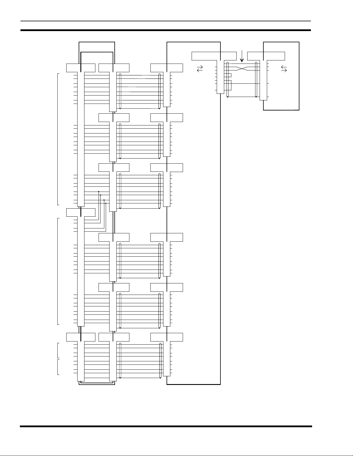
LBI-39128 INTERCONNECTION DIAGRAM
25-Pair Cable
to First Row
of Cabinets.
25-Pair Cable
to Second Row
of Cabinets.
Connect Directly
to Power Sensor
for Ant #1.
Connect Directly
to Power Sensor
for Ant #2.
25 PR (M)
Xmtr #1
Xmtr #2
Xmtr #3
Xmtr #4
Xmtr #5
Xmtr #6
Xmtr #7
Xmtr #8
Xmtr #9
Xmtr #10
Xmtr #11
Xmtr #12
25 PR (M)
Xmtr #11
Xmtr #12
Xmtr #13
Xmtr #14
Xmtr #15
Xmtr #16
Xmtr #17
Xmtr #18
Xmtr #19
Xmtr #20
Forward
Power
Reflected
Power
Forward
Power
Reflected
Power
EDACS Interface Panel
19D904009G12
"POWER SENSOR"
19C852632G1
J1 J3
1
26
3
28
5
30
7
32
9
34
11
36
13
38
15
40
17
42
19
44
21
46
23
48
J2
25 PR (F)
1
26
3
28
5
30
7
32
9
34
11
36
13
38
15
40
17
42
19
44
J9 J8
1
6
2
7
3
8
4
9
DB-9 (F)25 PR (F)
5
9
4
8
3
7
2
6
1
P2
J4
DB-9 (M) Cable
DB-9 (F)
5
9
4
8
3
7
2
6
1
J5
DB-9 (F)
5
9
4
8
3
7
2
6
1
J6
DB-9 (F)
DB-9 (M) DB-25 (F)
5
9
4
8
3
7
2
6
1
J7
DB-9 (F)
5
9
4
8
3
7
2
6
1
DB-9 (F)DB-9 (F)
1
6
2
7
3
8
4
9
55
188D6466P2
188D6466P2
188D6466P2
188D6466P2
188D6466P2
188D6466P1
Interconnect
Interconnect
Interconnect
CableDB-9 (M)
Interconnect
Cable
Interconnect
Cable DB-25 (F)DB-9 (M)
Interconnect
CableDB-9 (M) DB-25 (F)DB-9 (M)
DB-25 (F)DB-9 (M) Cable
DB-25 (F)
DB-25 (F)
P3P2
P3
P3P2
P3P2
P3P2
P3P2
PORT #1
DB-25 (M)
13
25
12
24
11
23
10
22
PORT #2
DB-25 (M)
13
25
12
24
11
23
10
22
PORT #3
DB-25 (M)
13
25
12
24
11
23
10
22
PORT #4
DB-25 (M)
13
25
12
24
11
23
10
22
PORT #5
DB-25 (M)
13
25
12
24
11
23
10
22
PORT #7
DB-25 (M)
13
25
12
24
11
23
10
22
Power Monitor Unit
Input
Return
Input
Return
Input
Return
Input
Return
Input
Return
Input
Return
Input
Return
Input
Return
Input
Return
Input
Return
Input
Return
Input
Return
Input
Return
Input
Return
Input
Return
Input
Return
Input
Return
Input
Return
Input
Return
Input
Return
Input
Return
Input
Return
Input
Return
Input
Return
350A1380P1
AI001
AI002
AI003
AI004
AI005
AI006
AI007
AI008
AI009
AI010
AI011
AI012
AI013
AI014
AI015
AI016
AI017
AI018
AI019
AI020
AI025
AI026
AI027
AI028
Right VDT Interface
DB-25 (F)
Tx Data
Rx Data
RTS
CTS
DSR
Ground
DTR
1
2
3
4
5
6
7
20
Interconnect Cable
19D903880P101
P1
Jumper in P1
Jumper in P1
P2
Port 29 (PMU)
RJ11-8 (F)
1
Shield
2
Tx Data
3
Rx Data
7
Signal GND
S
Connector Shield
Controller
19D149302P9
PMU Interconnection Diagram
EDACS Site Controller Cabinet
38
 Loading...