

Ericsson LBI-39125A, EDACS M-RK-II Operator's Manual
LBI-39125A
Operator’s Manual
EDACS®
M-RK-II SCAN
PORTABLE RADIO
ERICSSONZ

NOTICE!
This manu al co vers Ericss o n and General Electric pr od ucts
manufact u red and sold by Er ics s o n Inc.
NOTE!
Repairs to this equipment should be made only by an authorized service technician or facility designated by the supplier.
Any repairs, alterations or substitution of re commended parts
made by the user to this equipment not approved by the
manufacturer could void the user’s authority to operate the
equipment in addition to the manufacturer’s warranty.
NOTE
The software contained in this device is copyrighted by
Ericsson Inc. Unpublished rights are reserved under the
copyright laws of the United States.
This manual is published by Ericsson Inc., without any
warranty. Improvements and changes to this manual necessitated by typograp hical erro rs, inaccura cies of cu rrent information, or improvements to programs and/or equipment, may be
made by Ericsson Inc., at any time and without notice. Such
changes will be incorporated into new editions of this manual.
No part of this manual may be reproduced or transmitted in
any form or by any means, elec tronic or mechanical, inc luding
photocopying and recording, for any purpose, without the
express written permission of Ericsson Inc.
Copyright © Octo be r 19 94 , Ericsso n GE Mobile Communication s Inc.
2

TABLE OF CONTENTS
INTRODUCTION . . . . . . . . . . . . . . . . . . 7
USER IN TERFAC E . . . . . . . . . . . . . . . . . 8
BUTTONS AND KNOBS . . . . . . . . . . . . . 11
KEYPAD . . . . . . . . . . . . . . . . . . . . . 13
DISPLAY . . . . . . . . . . . . . . . . . . . . . 15
Messages . . . . . . . . . . . . . . . . . . 16
Status Indicators . . . . . . . . . . . . . . . 21
UNIVERSAL DEVICE CONNECT OR (UDC) . . . 23
ALERT TONES . . . . . . . . . . . . . . . . . . 24
Call Originate . . . . . . . . . . . . . . . . . 24
Autokey (Trunked Mode Only) . . . . . . . . 24
Call Queued (Trunked Mode Only) . . . . . 24
System Busy (Trunked Mode Only) . . . . . 25
Call Denied (Trunked Mode Only) . . . . . . 25
Carrier Control Timer . . . . . . . . . . . . . 25
Low Battery Warning . . . . . . . . . . . . . 25
Low Battery Al ert (Transmit Lo ck out) . . . . 26
Key Press Alert . . . . . . . . . . . . . . . . 26
OPERATION . . . . . . . . . . . . . . . . . . . . 26
TURNING ON THE RADIO . . . . . . . . . . . . 26
SELECTION MODE RULES . . . . . . . . . . . 27
BUTTON AND KEYPAD REASSIGNMENT . . . 32
SYSTEM/GROUP/CHANNEL SELECTION . . . 33
System Selection . . . . . . . . . . . . . . . 33
Group And Ch annel Sel ec ti on . . . . . . . . 35
TRUNKED MODE OPERATION . . . . . . . . . 36
Receiving A Call . . . . . . . . . . . . . . . 36
Sending A Call . . . . . . . . . . . . . . . . 37
Emergency Operation . . . . . . . . . . . . 38
Receiving An Emergency Call . . . . . 38
Declaring An Emergenc y Call . . . . . . 39
Wide Area System Scanning . . . . . . . . 40
ProSound . . . . . . . . . . . . . . . . . 40
Scanning Trunked Groups . . . . . . . . . . 41
Adding and Deleting Groups on
Scan List . . . . . . . . . . . . . . . . 41
Turning Scan On . . . . . . . . . . . . 42
3

Turning Scan Off . . . . . . . . . . . . 43
INDIVIDUAL CALLS . . . . . . . . . . . . . . . 43
Receiving And Responding To An Individual Call
(Trunked Mode Only ) . . . . . . . . . . . . 43
Sending An Individual Call
(Trunked Mode Only ) . . . . . . . . . . . . 44
TELEPHONE INTERCONNECT CALLS . . . . 45
Receiving A Telephone Interconnect Call
(Trunked Mode Only ) . . . . . . . . . . . . 45
Sending A Telephone Interconnect Call
(Trunked Mode Only ) . . . . . . . . . . . . 45
DTMF Overdial / Conventional Mode
Telephone Interconnect . . . . . . . . . . . 47
PORTA BLE DATA . . . . . . . . . . . . . . . . . 48
DISPLAYS . . . . . . . . . . . . . . . . . . . . 49
DAT A OFF OPERATION . . . . . . . . . . . . . 49
DAT A ON OPERATION . . . . . . . . . . . . . 50
EXITING DATA CALLS . . . . . . . . . . . . . . 50
SCAN LOCKOUT MODE . . . . . . . . . . . . 51
DAT A LOCKOUT MODE . . . . . . . . . . . . . 52
STA TUS OPERATION . . . . . . . . . . . . . . . 52
STATUS OPERATION . . . . . . . . . . . . . . 52
EDACS CONVENTIONAL P1 SCAN . . . . . . . 53
DYNAMIC REGROUP OPERATION . . . . . . . 53
EMERGENCY OPERA TION . . . . . . . . . . . 54
CONVENTIONAL MODE OPERATION . . . . . 54
Receiving A Call . . . . . . . . . . . . . . . 54
Sending A Call . . . . . . . . . . . . . . . . 55
Emergency Operation . . . . . . . . . . . . 56
Using 5-Tone Signalling for
Emergency Declaration . . . . . . . . . . . . . 57
Tone Encode Transmission . . . . . . . . . 58
Scanning Conventional Channels . . . . . . 58
Adding and Deleting Channels on Scan List 59
Turning Scan On . . . . . . . . . . . . 61
Turning Scan Off . . . . . . . . . . . . . . 61
AEGIS AND VOICE GUARD OPERATION . . . . 61
VOICE MODES . . . . . . . . . . . . . . . . . 61
4

Clear Modes . . . . . . . . . . . . . . . . . 63
Aegis Digital Mode . . . . . . . . . . . . . . 63
DTMF . . . . . . . . . . . . . . . . . . . . . 64
Error Messages . . . . . . . . . . . . . . . 64
Aegis Private And Voice Guard
Private Modes . . . . . . . . . . . . . . . . 65
Transferring Keys Int o Th e Rad io . . . . 66
Displaying The Currently Used
Cryptographic Key Number . . . . . . . 67
Key Zero . . . . . . . . . . . . . . . . . 68
Private Operation . . . . . . . . . . . . . . 68
Receiving An Encrypted Call . . . . . . 68
Transmitting An Encrypted Call . . . . . 69
Scanned Group Calls . . . . . . . . . . 70
MACRO KEY OPERA TION . . . . . . . . . . . . . 70
OPERATING RULES AND REGULATIONS . . . . 71
OPERATING TIPS . . . . . . . . . . . . . . . . . 73
BATTERY PACKS . . . . . . . . . . . . . . . . . . 73
CHARGING THE BATTER Y PACK . . . . . . . . 73
RECHARGEABLE BATTERY PACK DISPOSAL . 74
INSTALLING THE BATTERY PACK . . . . . . . 75
REMOVING THE BATTERY PACK . . . . . . . . 76
INTRINSICALLY SAFE USAGE . . . . . . . . . . 76
BATTERY PACKS . . . . . . . . . . . . . . . . . 76
ACCESSORIES . . . . . . . . . . . . . . . . . . 77
GLOSSARY . . . . . . . . . . . . . . . . . . . . . 78
OPERATOR’S RADIO SETUP . . . . . . . . . . . 81
WARRANTY . . . . . . . . . . . . . . . . . . . . 82
NICKEL-CADMIUM BATTERY WARRANTY . . . . 83
5

This page intentionally left blank
6

INTRODUCTION
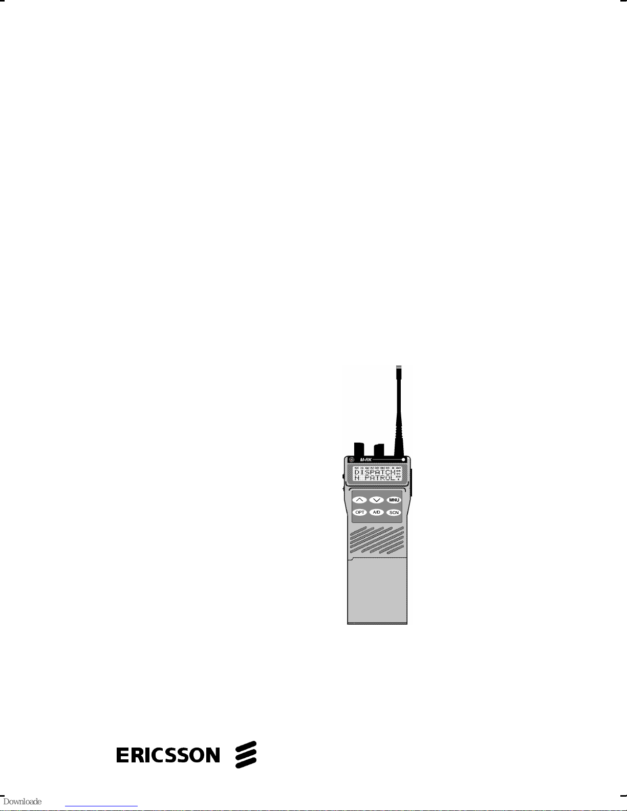
This manual describes how to use the EDACS M-RK
II Scan Portable Radio. The M-RK II Scan is a synthesized, microprocessor-based, high performance portable FM radio providing reliable two-way communications in both the Enhanced Digital Access Communications System (EDACS) trunking environment and conventional communication systems.
In the EDACS or trunked system mode, the user
selects a communications system and group. In this
mode, channel selection is transparent to the user and
is controlled via digital communication with the system
controller. This provides advanced programmable features and fast access to communication channels.
In the conventional mode, the user selects a channel
and directly communicates on that channel. In this mode,
a system refers to a set of channels. A channel is a
transmit/receive radio frequency pair.
The exact operation of the radio will depend on the
operating mode, the radio’s programming, and the particular radio system. Most features described in this
manual may be enabled or disabled through programming. Consult the system administrator for the particular
features that are programmed into the M-RK II Scan.
7

USER INTERFACE
The M-RK II Scan operating controls are located on
the radio’s front, top and left panels. A 6-button keypad,
liquid crystal display (LCD) for radio status information,
microphone and speaker are on the front panel. The top
panel houses a rotary SYSTEM/GROUP/CHANNEL
knob, POWER ON-OFF/VOLUME control knob and a
protected red EMERGENCY button. An OPTION button,
CLEAR/MONITOR button and the Push-To-Talk (PTT)
button are all located on the left side panel. The Universal
Device Connector (UDC) is located on the right panel
and is used while programming the radio and for accessory connection.
The keypad is used for activation of various EDACS
or conventional features such as menu selection or scan
operations.
The display has two, eight-alphanumeric-character
lines used to show the operational mode of the radio. 15
status indicators, used to indicate various operating conditions such as transmitter on, channel busy, scanning,
or low battery, are located above and to the right side of
the character lines within the display. A back light illuminates the display and the keypad for nighttime use.
8
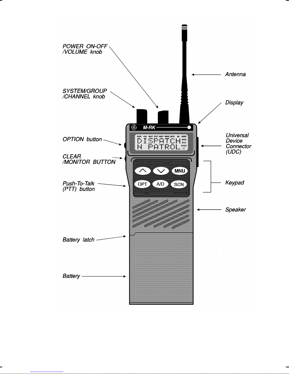
Figure 1 - M-RK II Scan Portable Radio
9
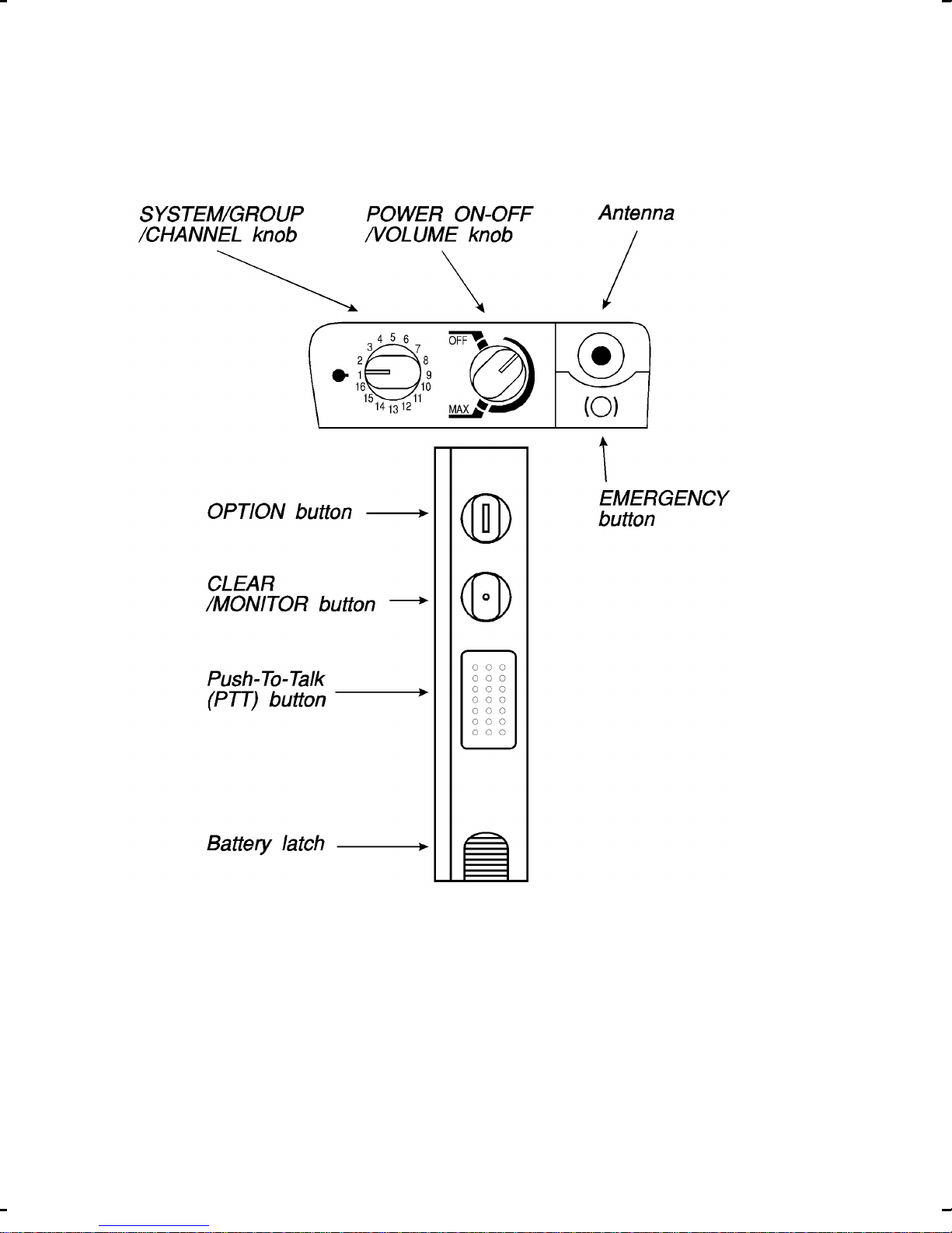
Figure 2 - Top And Partial Left Panel Views
10

BUTTONS AND KNOBS
This section describes the primary function of the
button and knob controls. Other functions associated
with these controls are detailed in later sections.
SYSTEM/
GROUP/
CHANNEL
KNOB
POWER
ON-OFF/
VOLUME
KNOB
Selects systems or groups/channels
(depending on programming). This
is a 16 - position rotary knob. See
SYSTEM/ GROUP/CHANNEL SELECTION for details.
Applies power to the radio and adjusts the receiver’s volume. Rotating
the control clockwise out of detent
applies power to the radio. A single
alert tone sounds (if enabled through
programming) to indicate the radio is
operational.
Rotating the control clockwise increases the volume level. Minimum
volume levels may be programmed
into the radio to prevent missed calls
due to a low volume setting. While
adjusting the volume the display will
momentarily indicate the volume
level (i.e. VOL = 31). The volume
range is from a minimum programmed level of zero (displayed as
OFF in the display) up to 31 which is
the loudest level.
11

EMER-
Provides single button emergency
GENCY
BUTTON
OPTION
BUTTON
(Side)
CLEAR/
MONITOR
BUTTON
channel access. See the EDACS
and conventional emergency sections for more details.
Programmable per system.
Serves several purposes depending
on the operating mode. In trunked
mode, the CLEAR/MONITOR button
exits the current operation and removes all displays associated with it.
The radio and display then return to
the group receive state. In conven-
PUSH-TO-
TALK BUT-
TON (PTT)
tional mode, pressing this button unmutes the receiver so activity on the
selected channel can be monitored.
When pressed and held for approximately 3 seconds, this button toggles conventional channel decoding/encoding (Channel Guard, Digital Channel Guard, T99) on and off if
programmed for the selected channel and scan disabled.
Enables the radio’s transmitter. Releasing PTT returns the radio to the
receive mode.
12
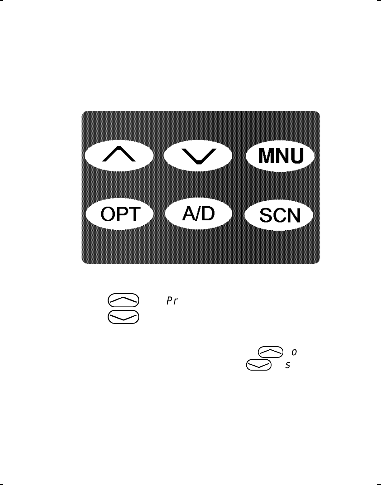
KEYPAD
The keypad layout has a total of 6 keys. The keys
have special functions and are labeled as such using a
symbol or abbreviated word describing its primary function. Numeric entry is a secondary function of the keys.
Each key is described below.
Figure 3 - M-RK II Scan Keypad
,
.
Primary function - changes the sys tem or group/channel (depending on
programming); secondary function changes to a selection for items
within a list. Press
increasing order,
.
,
to scroll in
to scroll in decreasing order. To auto-ramp press
and hold the key .
13
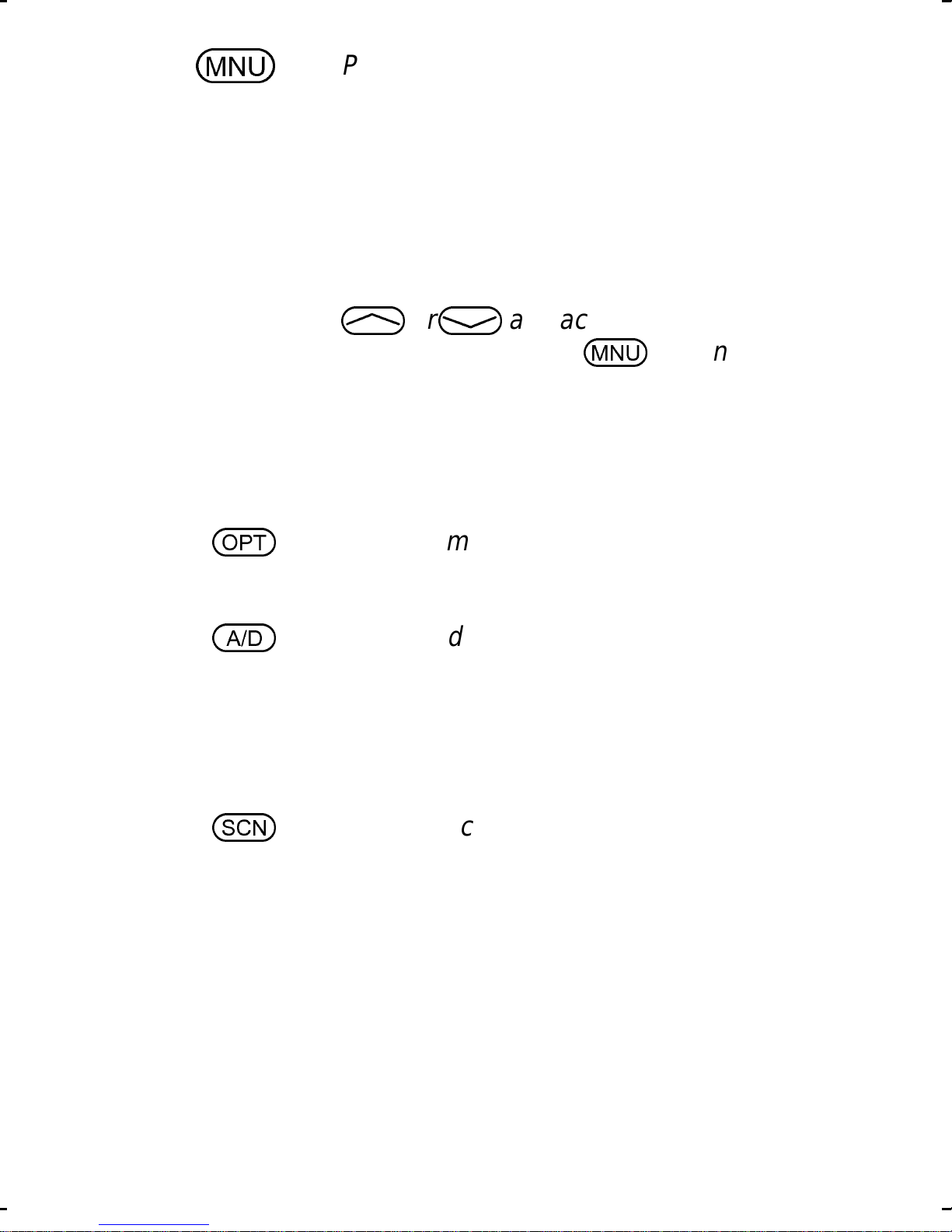
m
Primary function - accesses the
menu list. This is a list of additional
features that are not available directly from the keypad. See MENU
for details. Secondary function - activates a selected item within a list.
After the menu list is accessed, s elect a menu item from the list via
o
a
, or .
key . Once activated,
and activate it with this
m
continues
its secondary function for activating
a selected parameter setting until the
radio returns to its normal receive
state. This is similar to an enter key .
Programmable per system.
Adds or deletes selected groups or
channels from the scan list of the currently selected system. See trunked
and conventional scan section for
details.
s
14
Toggles scan operation on and off.
When the radio is scanning, SCN is
on and all groups or channels in the
scanlist of the currently selected system are scanned.
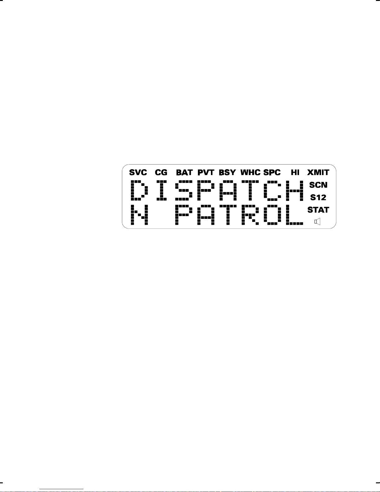
DISPLAY
The radio’s display is shown below . The two character
lines are used to display system, group and channel
names and also operational messages to the user . Each
line contains eight alphanumeric character blocks. The
15 status indicators are used to show the various operating conditions of the radio. If the display back-lighting
is programmed on, the display will illuminate for a short
period when any of the controls are operated.
Line 1
Line 2
Figure 4 - M-RK II Scan Display
The two display lines can be inverted to permit easy
viewing if the radio is worn on a belt or placed into a
vehicular charger . Refer to the MENU section to change
the display (invert or contrast).
15

Messages
During radio operation, various messages are displayed on either line one or line two. Typical messages
include control channel status information, such as system busy or call denied, or messages associated with the
radio’s operation, (i.e. volume or contrast adjust). These
messages are described below.
Message Name Description
QUEUED
SYS BUSY
Call Queued - Trunked mode
only. Indicates
the system has
placed the call in
a request queue.
System Busy - Trunked mode
only. Indicates
the system is
busy, no channels are currently
available, the
queue is full or an
individual call is
being attempted
DENIED
Call Denied - Trunked mode
16
to a radio that is
currently transmitting.
only. Indicates
the radio is not
authorized to op-

erate on the selected system
CC SCAN
WA SCAN
Control Channel Scan - Trunked mode
only. Indicates
the control channel is lost and the
radio has entered
the Control
Channel Scan
mode to search
for the control
channel.
Wide Area Scan - Trunked mode
only. Indicates
the control channel is lost and ra-
TALKARND
dio has entered
the Wide Area
Scan mode to
search for a new
system (if enabled through
programming).
Talk-around - Conventional
mode only. Indicates the radio is
operating on conventional channels in talkaround mode (no
repeater).
17

*RXEMER*
Receive Emergency - Trunked mode
only. Indicates an
emergency call is
being received.
This message will
be flashing on
line two.
*TXEMER*
VOL = 31
Transmit Emergency - Trunked mode
only. Indicates an
emergency call
has been transmitted. This message will be flashing on line two.
Volume Level - Indicates the cur-
rent volume level.
The volume level
display ranges
from OFF (silent)
to 31 (loudest).
LOW BATT
18
Battery Low - Indicates the bat-
tery level is too
low for transmission. This message displays
when pressing
PTT and transmitting is disabled due to the
low battery condition.

UNKNOWN
Unknown ID - Trunked mode
only. Indicates an
individual call is
being received by
an unknown radio ID. This bypasses when the
call is updated.
TX DATA
RX DATA
DATA OFF
Transmit Data - Trunked mode
only. Indicates
when a data call
is being transmitted. Displayed on
line one.
Receive Data - Trunked mode
only. Indicates
when a data call
is being received.
Displayed on line
one.
Data Off - Trunked mode
DATA ON
only. Indicates
when radio is in
data disable
state. Displayed
on line one.
Data On - Trunked mode
only. Indicates
when radio is toggled to data enable state. Dis-
19

played on line
one for two seconds.
KEY ZERO
PVT DIS
FRCD PVT
Key Zero - Indicates that
cryptographic
keys have been
erased from radio
memory .
Private Disabled - Indicates that the
group or channel
is not programmed for private mode operation.
Forced Private - Indicates that
NO KEY #
group or channel
is pre-programmed for private mode operation and clear
mode is not possible.
No Key Number - Indicates that the
correct cryptographic key is not
loaded for the selected group or
channel.
20

Status Indicators
The 15 status indicators show the various operating
characteristics of the radio. The indicators show operating modes and conditions as follows:
SVC T runked mode only.
ON - indicates the radio is in an EDACS
service area and is in communication with
the site controller via the control channel
(CC).
FLASHING - indicates the EDACS is in
the failsoft mode (if enabled through programming).
OFF - indicates the radio is out of range or
the control channel is not available.
CG Conventional mode only .
ON - indicates Channel Guard encode/decode is enabled on the selected conventional channel.
BAT ON - indicates the battery pack’s charge is
low and needs recharging.
PVT Private
ON - indicates the group or channel is enabled to receive encrypted messages.
FLASHING - indicates an encrypted
transmission is being received.
21

BSY Channel Busy -
In trunked mode:
ON - indicates the radio is transmitting
or receiving a call on the working channel.
FLASHING - indicates a call has been
queued.
In conventional mode:
ON - indicates a call is being received.
WHC Who Has Called (trunked mode only)
ON - indicates an individual call has been
received, but not responded to. The indicator turns OFF if the individual call mode
is entered, the system is changed or the
radio is turned off and back on.
SPC ON - indicates the radio is in the special
call select/entry mode (Individual or Telephone Interconnect).
HI ON - indicates the selected group or chan-
nel is selected to transmit at high power .
OFF - indicates the selected group or
channel is selected to transmit at low
power.
XMIT ON - indicates the radio is transmitting.
When operating in a trunked system, the
radio may be programmed to automatically transmit (without pressing PTT) to
maintain digital communication with the
22

site controller. will turn on whenever
XMIT
the radio is transmitting.
SCN ON - indicates the scan mode is enabled.
S ON - indicates the selected group or chan-
nel is in the scan list.
1 ON - (conventional mode only) indicates
the selected channel is designated as the
priority-one scan channel.
2 ON - (conventional mode only) indicates
the selected channel is designated as the
priority-two scan channel.
ON - (conventional mode only) indicates
that the selected channel has T99 decode
option enabled.
UNIVERSAL DEVICE CONNECTOR (UDC)
The Universal Device Connector (UDC) provides
connections for external accessories such as a headset
or a speaker-microphone. When the radio is locked in a
vehicular charger/repeater the UDC provides the audio
and control connections between the radio and the vehicular charger/repeater. The UDC is also used to program and service the radio.
23

ALERT TONES
The M-RK II Scan radio also provides audible alert
tones or "beeps" to indicate the various operating conditions. These alert tones can be enabled or disabled
through programming.
Call Originate
A short mid-pitched alert tone sounds after keying the
radio (Push-T o-T alk button is pressed). This indicates the
radio has been assigned a working channel or that the
radio is transmitting on a conventional channel and voice
communication may begin immediately. In conventional
mode, this tone may be delayed after the PTT button is
pressed due to GE-STAR signalling (if enabled through
programming).
Autokey (Trunked Mode Only)
After being placed in queue or releasing the PTT
button prior to a working channel assignment, the site
calls the radio when a channel becomes available. At this
point, the radio automatically keys the transmitter
(autokey) for a short period to hold the channel. The radio
sounds a mid-pitched tone when it is clear to talk; immediately press the PTT button to keep the assigned channel.
Call Queued (Trunked Mode Only)
A high-pitched tone after pressing the PTT button
indicates the system has plac ed the call request in the
queue. The receiving unit(s) also hear the tones, indicat-
24

ing they will receive a call shortly. If the the PTT button
is released, the radio will autokey whenever a channel
becomes available (see Autokey).
System Busy (Trunked Mode Only)
Three low-pitched beeps will be heard if the radio is
keyed when the system is busy, if no channels are
available for sending the message, if the call queue is
full, or if an individual call is being attempted to a radio
that is transmitting. Releasing the PTT button and re-keying initiates a new channel request.
Call Denied (Trunked Mode Only)
If the radio is keyed and a low pitched tone is heard
then the radio is not authorized on the system that has
been selected.
Carrier Control Timer
If the programmed time for continuous transmission
is exceeded, five short high-pitched warning tones followed by a long low-pitched tone will be heard. The
transmitter will shut down shortly after hearing the alert,
interrupting communications. Release and re-key the
PTT button to maintain communications . This will reset
the carrier control timer and turn the transmitter back on.
Low Battery Warning
A low-pitched tone is heard and comes on
indicating that the battery voltage is low. The radio will
continue to receive and transmit.
BAT
25

Low Battery Alert (T ransmit Lockou t)
If the radio is keyed and a low-pitched tone or two
tones repeated until PTT or CLEAR button is pressed
(either condition is pre-programmable) is heard and LOW
BATT is displayed, the battery is discharged and the
radio will not transmit. The radio will still be able to receive
calls until the battery is discharged beyond the point of
operation, after which the battery will need to be recharged to resume normal operation.
Key Press Alert
A short tone or "beep" sounds to indicate a key has
been pressed. A short low-pitched tone indicates no
action was taken because the key is not active in the
current mode.
OPERATION
TURNING ON THE RADIO
Rotate the POWER ON-OFF/VOLUME knob clockwise, out of detent to turn the radio on. (Ensure the
antenna and battery pack are properly connected prior
to power on.) A short beep (if enabled through programming) indicates the radio is ready for operation. The
display indicates, if programmed, the last selected system name on line one and the last selected group or
channel name on line two.
In the EDACS trunked environment, upon acquisition
of the control channel, will come on. If communi-
cation with the system’s control channel cannot be es-
26
SVC
 Loading...