

Page 1
LBI-39012B
Operator’s Manual
MDXTM Conventional
Mobile Radio
ERICSSONZ
Page 2

TABLE OF CONTENTS
Page
SAFETY INFORMATION . . . . . . . . . . . . . . . 4
SAFE DRIVING RECOMMENDATIONS FOR USERS
OF MOBILE RADIOS* . . . . . . . . . . . . . . . . 5
OPERATING PROCEDURES . . . . . . . . . . . . . 6
INTRODUCTION . . . . . . . . . . . . . . . . . . . 7
CONTROLS, INDICATORS, AND DISPLAYS . . . . 9
CONTROLS . . . . . . . . . . . . . . . . . . . . 9
MENU . . . . . . . . . . . . . . . . . . . . . . . 9
DISPLA Y INDICATORS . . . . . . . . . . . . . 12
NOTICE!
This manual covers Ericsson and General Electric products manufactured and
sold by Ericsson Inc.
NOTICE!
Repairs to this equipment should be made only by an authorized service
technician or facility designated by the supplier. Any repairs, alterations or
substitution of recommended parts made by the user to th is equipment not
approved by the manufacturer could void the user’s authority to operate the
equipment in addition to the manufacturer’s warranty.
NOTICE!
The software contained in this device is copyrighted by Ericsson Inc.
Unpublished rights are reserved under the copyright laws of the United
States.
This manual is published b y
changes to this manual necessitated by typographical errors, inaccuracies of current
information, or improvem ents to program s and/or equip ment, may be made by
Inc.
, at any time and without notice. Such changes will be incorporated into new editions
of this manual. No part of this manual may be reproduced or transmitted in any form
or by any means, electronic or mechanical, including photocopying and recording, for
any purpose, without the express written permission of
Copyright © December 1993, Ericsson GE Mobile Communications Inc.
2
Ericsson Inc.
, without any warranty. Improvements and
Ericsson
Ericsson Inc.
Page 3

TABLE OF CONTENTS
Page
DISPLAY ALPHA INDICATORS . . . . . . . . 12
ALERT TONES . . . . . . . . . . . . . . . . . . . . 13
OPERATING THE RADIO . . . . . . . . . . . . . . 13
TURNING THE RADIO ON . . . . . . . . . . . 13
SELECT . . . . . . . . . . . . . . . . . . . . . . 14
FRONT PANEL SQUELCH ADJUSTMENT . . 14
RECEIVING A CALL . . . . . . . . . . . . . . 14
SENDING A MESSAGE . . . . . . . . . . . . . 14
SCAN OPERATION . . . . . . . . . . . . . . . . . . 15
SCAN SETUP . . . . . . . . . . . . . . . . . . . 15
RECEIVER SCAN RATE . . . . . . . . . . . . 16
USING THE RADIO WITH SCAN . . . . . . . 17
AEGIS OPERATION . . . . . . . . . . . . . . . . . 2 2
VOICE MODES . . . . . . . . . . . . . . . . . . 22
CLEAR MODES . . . . . . . . . . . . . . . . . 23
AEGIS DIGITAL MODE . . . . . . . . . . . . . 23
DTMF . . . . . . . . . . . . . . . . . . . . . . . 23
AEGIS VGE DIGITAL MODES . . . . . . . . . 23
TRANSFERRING KEYS INTO THE RADIO . . 24
DISPLAYING THE CURRENTLY USED
CR YPTOGRAPHIC KEY NUMBER . . . . . . 24
KEY ZERO . . . . . . . . . . . . . . . . . . . . 25
VGE DIGITAL OPERATION . . . . . . . . . . . . . 25
RECEIVING AN ENCRYPTED CALL . . . . . 25
TRANSMITTING AN ENCRYPTED CALL . . 25
Outside Address . . . . . . . . . . . . . . 26
Channel Guard . . . . . . . . . . . . . . . 26
GE•STAR . . . . . . . . . . . . . . . . . . 26
OPTIONS . . . . . . . . . . . . . . . . . . . . . . . 27
Type 99 Option . . . . . . . . . . . . . . . 27
Public Address Option . . . . . . . . . . . 27
INTERNAL/EXTERNAL SPEAKER . . . . . . 28
AVAILABLE OPTIONS . . . . . . . . . . . . . . . . 29
OPERATING TIPS . . . . . . . . . . . . . . . . . . . Back Cover
3
Page 4

SAFETY INFORMATION
The operator of any mobile radio should be aware of certain hazards
common to the operation of vehicular radio transmissions.
A list of possible hazards are:
1. Explosive Atmosphere s
Just as it is dangerous to fuel a vehicle with the motor running, be
sure to turn the radio off while fueling the vehicle. Do not carry
containers of fuel in the trunk.
2. Interference to Vehicular Electronics Systems
Electronic fuel injection systems, electronic anti skid braking systems, etc., are typical of the type of electronic devices that may
malfunction due to the lack of protection from radio frequency energy
present when transmitting. If the vehicle contains such equipment,
consult the dealer for the make of the vehicle and enlist his aid in
determining if such electronic circuits perform normally when the
radio is transmitting.
3. Dynamite Blasting Caps
Dynamite blasting caps may be caused to explode by operating a radio
within 500 feet of the blasting ca ps. Always obey the " Turn Off T wo
Way Radios" signs posted where dynamite is being used. When
transporting blasting caps in your vehicle:
a. Carry the blasting caps in a closed metal box with a soft lining.
b. Leave the radio OFF whenever the blasting caps are be ing put
into or removed from the vehicle.
4. Radio Frequency Energy
To prevent burns or related physical injury from radio frequency
energy, do n ot operate the transmitter when anyone outside of the
vehicle is within two feet of the antenna.
5. Liquefied (LP) Gas Powered Vehicles
Mobile radio installations in vehicles powered by liquefied petroleum
gas with the LP gas container in the trunk or other sealed-off space
4
Page 5

within the interior of the vehicle must conform to the National Fire
Protection Association standard (NEPA) 58 which requires that:
a. The space containing the radio equipment shall be isolated by a
seal from the space containing the LP gas container and its
fittings.
b. Outside filling connections shall be used for the LP gas container .
c. The LP gas container shall be vented to the outside of the vehicle.
SAFE DRIVING RECOMMENDATIONS FOR USERS OF MOBILE
RADIOS*
Read the literature on the safe operation of the radio.
• Keep both hands on the steering wheel and the microphone in its cradle
whenever the vehicle is in motion.
• Place calls only when vehicle is stopped. Use recall dialing to speed the
time it takes to call.
• When talking from a moving vehicle is unavoidable, drive in the slower
lane. Keep conversations brief.
• If conversation requires taking notes or complex thought, stop the
vehicle in a safe place and continue the call.
Whenever using a mobile radio exercise caution.
*As recommended by the AAA
5
Page 6

OPERATING PROCEDURES
Two-way FM radio systems must be operated in accordance with the rules
and regulations of the Federal Communications Commission (FCC). Operators
of two-way radio equipment must be thoroughly familiar with the rules that
apply to the intended type of radio operation. Following these rules will help
to eliminate confusion, assure the most eff icient use of e xisting radio channels,
and result in a smoothly functioning radio network. When using this two-way
radio remember these rules:
1. It is a violation of FCC rules to interrupt any distress or emergency
message. As the radio operates in much the same way as a te lephone
"party line", always listen to make sure that the line is clear - that no
one else in on t he air - befo re sending mes sages. If s omeone is se nding
an emergency message - such as reporting a fire, or asking fo r help
in an accident - KEEP OFF THE AIR! Emergency calls have
priority over all other messages.
2. Use of profane or obscene language is prohibited by Federal law.
3. It is against the law to send false call letters, or a false distress or
emergency message.
4. The FCC requires that conversations be kept brief and confined to
business. To save time, use coded messages whenever possible.
5. Using a radio to sen d per son al m essa ge s (except in an emergency) is
a violation of the FCC rules. Send only those messages that are
essential for business operation.
6. It is against F edera l la w to re peat o r othe rwise m ake kno wn anyth ing
overheard on the radio. Conversations between others sharing a
channel must be regarded as confidential.
7. The FCC requires the operator to identify himself at certain times by
means of call letters. Refer to the rules that apply to the particular type
of operation for the pro per procedure.
8. No changes or adju stment s sha ll b e made to t he eq uipme nt e xcept by
an authorized or certified electronics technician.
6
Page 7

INTRODUCTION
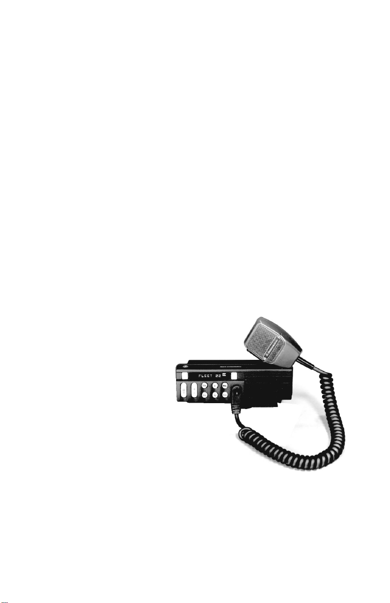
This manual describes how to use the MDX Conventional Mobile Radio.
The MDX is a synthesized, microprocessor-based, high performance simplex
mobile FM radio providing reliable two-way communications. Dire ct mobile
to mobile communication, when out of repeater range, is also provided.
In the Conventional mode, the user selects a channel and directly
communicates on that channel. In this mode, a system refers to a set of channels
and a channel is a transmit/receive radio frequency pair.
The exact operation of the radio will depend on the operating mode, the
radio’s programming, and the particular radio system. Most features described
in this manual ma y be ena ble d or di sa ble d th ro ugh p rogr am min g. Cons ult the
system administr ator f or the partic ular featu res th at ar e prog rammed into your
MDX radio.
The following feature encrypted options are standard with the MDX
conventional mobile radio:
PMPL3M Serial Control Unit (Control Head Operation)
PMPL3K Scan, Dual Priority
PMPL3F 16 channel operation
PMPL3G 32 channel operation
PMPL3H 64 channel operation
PMPL3J 128 channel opera ti on
The following feature encrypted options can also be ordered:
PMPL3C Type 99 Decode
PMPL3D Public Address and External Speaker Switch (Re-
quires option PMSU5A)
PMPL3E Emergency (GE-STAR) and GE-STAR ANI
7
Page 8
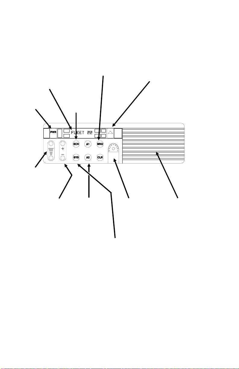
8-Character
Alphanumeric Dot
Matrix LED
allows you to identify
channel selections by
descriptive names.
Names, menu options, and
status information are
displayed here.
Scan Button
enables scan
operation for the
PWR
Volume Up/Down
Ramp
sets the volume
of the received audio.
selected system.
MENU
button allows access
to functions and options,
including scan add/delete for
modifying the radio’s scan
list and alarm on/off for the
external alarm option that
uses your horn or head lights
to signal an incoming call.
Emergency ID/ Alarm
(optional
sends an emergency
(GESTAR) alert and
identifying code to the
dispatcher. If no emergency
function is required, this can
be programmed as a
"HOME" switch.
)
Channel/SEL
Ramp
scrolls through
the names of channels
programmed into the
radio, displaying them
on the Dot Matrix
display.
8
Two Flex Keys
give you one-touch
access to the menu or
optional features.
Optional keycaps are
available to identify
the functions of
pre-programmed
buttons, including T99
decode, Scan Add/
Delete, Public
Address, Home,
Private, External
Alarm, and display
brightness.
Front-Mounted
Microphone
Connector
easy access to the
microphone and
programming
capabilities.
System Key
through the names of
the system (groups of
channels) programmed into the radio,
displaying them on
the Dot Matrix display
Figure 1 - MDX SCAN Radio
provides
scrolls
Front Mount
Speaker
with 4 watts
of audio. An optional
10-watt external
speaker is also
available, for use in
noisy environments.
Page 9

CONTROLS, INDICATORS, AND DISPLAYS
The MDX Conventional mobile radio contains ten buttons, an eight
character DOT MATRIX display and seven indicators (see Figure 1). In
addition, there are times when part of the eight character display is used to
display the radio status. Backlighting on buttons illuminate the Leg ends.
CONTROLS
POWER Momentary push-push switch. Press once to turn
the radio ON. Press again to turn the radio OFF .
VOLUME The momentary switches (auto ramping) VOL-
UME + and VOLUME -. Beeps each time the
VOLUME button is pressed, except when a call is
in process. Hold the button (up or down) to auto
ramp the volume.
MENU Momentary switch. The MENU button is used to
access options on the MDX mobile. Menu operation is coupled with the CHANNEL/SEL bu ttons
and the CLR button. To increment from one me nu
selection to the next, simply press and release the
MENU button. Press the CLR button to return to
normal operation. The menu choices are listed
below with a description of how to change the
choices (Note: You may have some or all of these
menu choices programmed in your radio, and they
may be programmed in a different order than presented here).
BACKLIGHT: Press the MENU button until
"BRIGHT" appears in the display. To change the
state of the backlight press the CHANNEL/SEL +
or - button.
PUBLIC ADDRESS: Press the MENU button
until "PUB ADDR" appears in the display. Press
PTT to transmit in PA mode.
SCAN ADD/DELETE: Press the MENU button
until "SCAN A/D" appears in the display. Use the
CHANNEL/SEL- button to step through the
group selections for the current system. Use the
CHANNEL/SEL + button to change the scan
state. An "S" is illuminated to the right of the
display if the group/channel has SCAN enabled.
9
Page 10
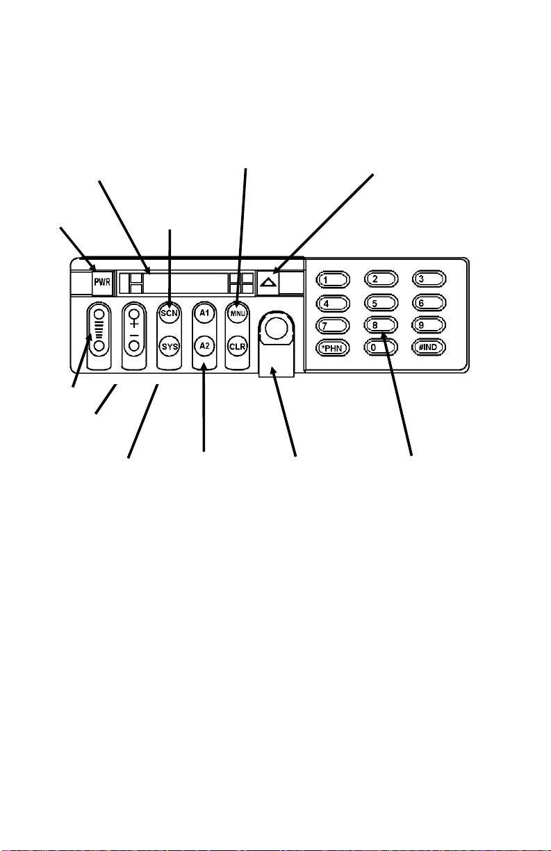
CONTROLS, INDICATORS, AND DISPLAYS
8-Character
Alphanumeric Dot
Matrix LED
allows you to identify
channel selections by
descriptive names.
Menu options, and status
information are displayed
here.
MENU
button allows access
to functions and options,
including scan add/delete for
modifying the radio’s scan
list and alarm on/off for the
external alarm option that
uses your horn or head lights
to signal an incoming call.
Emergency ID/ Alarm
(optional
sends an emergency alert and
identifying code to the
dispatcher. If no emergency
function is required, this can
be programmed as a
"HOME" switch.
)
PWR
Volume
Channel/SEL
Ramp
System Switch
through the names of
the systems and/or
channels programmed into the radio,
displaying them on
the Dot Matrix
display.
scrolls
Scan Button
Two Flex Keys
give you one-touch
access to the menu or
optional features.
Optional keycaps are
available to identify
the functions of
pre-programmed
buttons, including
Scan Add/ De le te,
Public Address,
Home, Private,
External Alarm, and
display brightness.
Front-Mounted
Microphone
Connector
easy access to the
microphone and
programming
capabilities.
provides
System Keypad
10-watt external
speaker must be used
with the System
model.
10
Figure 2 - MDX System Radio
Page 11

CONTROLS (CONT’D)
MENU - Cont. ALARM ON/OFF: Press the MENU b utton until
"ALM ON" or "ALM OFF" appears in the display .
Press the CHANNEL/SEL + or - buttons until the
desired state is selected. (Note: This enables or
disables the external alarm, e.g. horn or lights.)
SQUELCH Press and hold "Scan" button, use "volume" up to
loosen squelch and down to tighten squelch.
SYS Momentary switch. The SYS (SYSTEM) bu tton is
used to select system changes. System may be
incremented by pressing and releasing the SYS
button. Alternately, when the display shows the
System name, the CHANNEL/SEL buttons may be
used to incr ement or decrem ent the system se lections. (NO TE: The radio ma y be programmed with
wrap around on the system selection; this would
allow the radio to switch from the highest to lowest
system with one change instead of ramping all the
way through the list.)
CHANNEL/SEL Ramp Switch. The CHANNEL/SEL button is
used to increment or decr ement the current channel
selection. It is also used as described above to
increment/decrement the System. In conventional
mode, these buttons change the channel selection.
CLR Momentary switch. The CLR button is used to exit
from the menu operation, monitor a conventional
channel or end a special/individual call.
HOME/
EMERGENCY
FLEX KEYS
A1, A2
Momentary switch. The HOME or EMER-
GENCY button is used to select a home system, or
channel. The radio may be programmed to revert
to a particular system or channel within the selected or home system . It may also be pr ogrammed
to send an emergency message (GESTAR) when
pressed and held for approximately one second
(either on the selected system or on the Home
system).
The auxiliary buttons are used to access frequently
used menu selections quickly. They can also be
programmed as a HO M E, Ex t erna l A lar m, Pub l ic
Address, T99 decode, Pri vate, and Scan add/delete.
11
Page 12

NUMERIC KEYS
1-9, 0, *, #
DISPLAY INDICA TORS
The radio’s display is shown in Fig ure 3. The character line is used to
display system or area and group or channel names and also operational
messages to the user. The line contains eight Dot Matrix LED character s. The
7 status indicators are used to show the various operating conditions of the
radio.
TX On indicates the radio is transmitting.
BSY Lights when a channel is b usy (RF carrier present).
SCN ON indicates scan is enabled.
S ON indicates channel in scan list.
P1 ON indicates selected channel is a priority 1 chan-
On system radio, the twelve button keypad permits
transmission of DTMF digits.
Figure 3 - Sample MDX Display
nel.
P2 ON indicates selected channel is a priority 2 chan-
nel.
PVT ON indicates selected channel has been pre-pro-
grammed for AEGIS operation. Flashes indicates
receiving an encrypted digital voice call.
DISPLAY ALPHA INDICA TORS
The radio is capable of displaying status indicators in the alpha display.
Some of these messages will use the entire display while others use only two
or three characters. When the short me ssage is displayed, it may be on the right
or left of the display (PC programmable). It is separated from the normal
information with an indicator such as an asterisk ("*").
T99 T99 call received alternates with current channel
display.
T99 On Menu display indicating T99 option is enabled.
12
Page 13

DISPLAY ALPHA INDICA TORS - Cont .
T99 Off Menu display indicat i n g T9 9 o pt ion is disabled.
Pub Addr Public address option enabled.
ALER T TO NES
The MDX Conventional mobile radio generates a set of unique ale rt tones
to indicate operating status. The following section identif ies a nd describes the
alert tones used in the MDX radio.
SELF CHECK
TEST ALER T
CALL DISABLED
ALERT
CARRIER CONTROL
TIMER
T99 CALL RECEIVED After decoding a T99 call, the received signalling
One beep is sounded after the radio is turned on to
indicate that the radio has passed the self diagnostic
test. Optional in PC programmer .
You will hear a continuous low pitched tone when
your radio is set to a recei v e (decode ) only channel
and you press PTT on the microphone. This tone
indicates that you are not allowed to plac e a call on
this setting.
The Carrier Control Timer alert is a pulsing pitched
tone you will hear whenever you have kept the PTT
button continuously pressed for a preprogrammed
length of time. The transmitter shuts down when
the pulsing low pitched tone starts, interrupting
communications. T o maintain communications, release and re-key the microphone. This resets the
timer and turns the transmitter back on. The CCT
is a built in precaution against extended use of the
system.
2-tone is soun ded to alert yo u of th e incom ing call .
OPERATING THE RADIO
TURNING THE RADIO ON
1. Push the PO WER sw itch. The d isplay sho ws t he ch annel a lpha name
once power up is complete. When powering up, the last selected
Channel should be displayed unless the radio is programmed for a
preprogramme d power up. The radi o optionally gene rates a beep once
the power up sequence is complete.
13
Page 14

2. Set the volume using the VOLUME RAMP button. A short beep
sounds each time the VOLUME bu tton is pressed. The beeps will not
sound if a call is being received.
SELECT
T o select a different channe l when you have selected a con ventional system:
1. Press the CHANNEL/SEL + or - ramp button until the desired
channel name appears in the alphanumeric display. A tone sounds
each time the channel name changes unless the BSY indicator is on.
FRONT PANEL SQUELCH ADJUSTMENT
The squelch setting of the radio can be adjusted by the user through the
front panel controls. There are a total of 256 steps used internally to the radio
for the squelch level adjustment. The front panel allows adjustment through a
portion of that range.
With the radio on a conventional channel, press and hold the SCN button.
Then use the VOLUME ramp b utton to open and close the squelch. After setting
the squelch to the desired setting, release the SCN button to return the radio to
normal operation.
RECEIVING A CALL
1. Make sure that the radio is turned
selected using the CHANNEL/SEL + or - ramp b utton an d the SYS
button.
2. Press the CLR button to monitor the channel. Noise will be heard if
there is no activity on the channel. This function is also useful for
setting the desired volume level.
3. You will hear the voice message automatically if a valid message is
received by your radio.
SENDING A MESSAGE
1. Make sure the radio is turned ON, and the proper Channel and System
have been se l ected.
2. Press and hold the CLR switch and then adjust the VOLUME c ontrols
for the desired listening level. Release CLR switch.
14
ON, and the proper channel is
Page 15

3. Decide what you want to say. If you intend a lengthy message (or
several messages), the vehicle engine should be running to maintain
the battery ch arge.
4. Observe the BSY indicator and then press CLR the switch to assure
that the channel is not in use.
5. Remove microphone from the hanger, press the PTT switch and
identify yourself. The indicator will be shown each time the
PTT switch is pressed.
6. Release the PTT switch and wait for an answer to your call. Then
complete your message.
7. When the PTT switch is pressed continuously for a pre-programmed
time (default of 30 seconds), the carrier control timer (if enabled) will
sound a pulsed alert tone and unkey the transmitter. Release and press
the PTT switch again to reset the timer and resume conversation.
Always speak in a normal tone of voice. Hold the microphone
cupped in your hand and touching your cheek lightly. Speak
across the face of your microphone, not directly into it. Shouting
will degrade your transmission, so do not speak any louder than
normal.
TX
NOTE
SCAN OPERATION
SCAN SETUP
You may program your radio to scan a number of Channels for activity on
the selected system.
Starting Or Stopping SCAN
Press the SCAN button to alternate between Scan on (SCN indicator
illuminated) and Scan off (indicator dark).
Adding/Deleting To/From SCAN
SCAN should be off before changing the SCAN list.
1. Press the menu button until SCAN A/D is displayed.
2. Press the CHANNEL/SEL (-) button until the CHANNEL name is
displayed.
15
Page 16

3. Press the CHANNEL/SEL (+) button until the desired priority level
is displayed by the scan priority indicators on the right side of the
display; the choices are S, P2; P1 or all off (all off removes the channel
from the SCAN list).
4. Press the CLR button when completed to return to normal operation.
If your radio has one of the auxiliary keys preprogrammed to edit the SCAN
list, the list may be changed by using the CHANNEL/SEL buttons to display
the CHANNEL name, and then pressing the auxiliary key until the desired
level is displayed.
NOTES
1. The radio will remember the scan state through a power cycle
unless progr ammed with a pred efined power up state.
2. The radio may be programmed to stop scanning when the
microphone is removed from the hookswitch.
3. When the radio is programmed, a FIXED SCAN list can be
specified. If this is done, the SCAN list cannot be changed.
4. A previous channel with priority will become a non-priority scan
channel when a new priority channel is programmed.
The SCAN function allows monitoring of up to 16 receive channels on the
selected system. The scanned channels may be any frequency within the
frequency band limits of the radio and ma y be Channel Gu ard protected. All
scan functions are retained in memory, even if the 12 Volt vehicle battery is
disconnected.
Any channel may be scanned with or without a priority level. One channel
may be programm ed for Prior ity 1 (P1) a nd another for Priori ty 2 (P2) wi th
any or all remaining channels programmed as non-priorities.
RECEIVER SCAN RATE
The scan rate for the radio will vary depending upon the number of channels
programmed into the scan list and whether or not Channel Guard is
programmed. The scan rate will be faster when fewer channels are programmed into scan memory.
16
Page 17

Scan operation will be determined by the following conditions:
• PRIORITY 1, PRIORITY 2 and NON-PRIORITY PROGRAMMED
The Priority 1, Priority 2 and up to 14 remaining channels will be
scanned. Once a carrier is detected (and if programmed, the correct
Channel Guard is decoded), the display will indicate that channel.
Sampling of the Priority 1 and Priority 2 channels continues while
receiving a message. Should a Priority 1 or 2 channel carrier (and correct
Channel Guard) be detected while a non-priority channel is being
received, the applicable indicator, P1 or P2 ligh ts, and the channel is
switched to the Priority 1 or 2 channel regardless of what is being
received on the non-priority channel.
• NON-PRIORITY PROGRAMMED
Up to 16 non-priority channels may be scanned. Once a carrier is
detected (or correct Channel Guard is decoded) the digital display will
indicate that channel. Scanning will stop and rema in on the channel until
the carrier disappears; after a few seconds scanning resumes. The
channels are scanned in descending order.
USING THE RADIO WITH SCAN
The Selected Channel
The SELECTED channel is the channel in the display when scan is turned
on by pushing the SCAN switch. When a signal is not being recei ved, the ra dio
reverts to this channel for transmitting. When a signal is being received, the
radio can be PC programmed to either revert to the SELECTED channel or
remain on the received channel for transmission.
The SELECTED channel does not necessarily have to be a channel in the
scan list. The SELECTED channel will be temporarily entered into the scan
list and scanned until the SELECTED channel is changed.
When scan is turned off by pushing the SCAN switch, the radio will return
to the SELECTED channel.
Display
Channel indicator
While no signal is being received, the channel indicator will always show
the SELECTED channel. When an active channel is received, the channel
indicator will show the received channel.
17
Page 18

SCN indicator
When the SCAN button is pushed, the radio will light the SCN in dicator
and begin scanning. The SCN indicator will flash when the microphone is
placed off-hook to show the radio is no longer scanning (only if the radio is
PC programmed not t o s can off-hook).
Transmitting While In Scan:
Transmitter operation in scan is determined by the PC programming of the
radio’s personality. A flow chart is provided in this section to summarize the
scan operation described below.
• Off-hook scan not enabled (default):
With off-hook scan not enabled (normal def ault condition), all scanning
will stop when the microphone is placed off-hook. The SCN indicator
will flash to show all scanning has stopped. If a signal is not being
received when the mic is place d off -hook, the ra dio will transmit on the
SELECTED channel. If a signal is being rec eived when the mic is plac ed
off-hook, the radio can be PC programmed (using the "scan transmit
option") to either stay on the receive channel or re vert to the SELECTED
channel. When the mic is placed back on-hook, the radio will
immediately start scanning, even if the recei ved channel was still active.
• Off-hook scan enabled:
With off-hook scan enabled, moving the microphone off-hook will not
affect scan operation. The radio will continue scanning. If a signal is not
being received, the radio will transmit on the SELECTE D channel. I f a
signal is being received, the radio can be PC programmed (using the
"scan transmit channel" option) to either stay on the receive channel or
revert to the SELECTED channel when the mic PTT is keyed.
• On-hook
When the micropho ne is on-hoo k (in the microph one hanger) and th e
radio is not receiving a channel, the radio always transmits on the
SELECTED channel.
When the radio is receiving a channel the radio’ s personality can be programmed to transmit either on the received channel or the SEL ECTED
channel. If the radio was programmed for the SELECTED channel, the
display changes to the SELECTED channel when the transmitter is
keyed.
18
Page 19

Monitor (CLR) Switch Operation In Scan
The CLR switch does not operate while scanning in acti ve chan nels. When
a channel becomes active, the CLR switch operates only during the scan hang
time after the channel activity disappears.
Channel Changes In Scan
Pushing the channel switches (UP or DOWN) while scan is turned on will
change the SELECTED channel assignment. If a signal is being received and
the channel switches are pushed, the radio will revert to the new SELECTED
channel assignment. After 2 seconds, if no activity appears on the new
SELECTED channel, scanning will resume. If the SELECTED channel is
changed to a channel not in the scan list, the new channel will be temporarily
added to the scan list until the SELECTED channel is changed again.
• Temporary channel deletions
The SCAN function must be turned off to make any permanent changes
(additions, deletions, re-priorizations) to the scan list. While in scan,
temporary channel deletions may be made to the scan list. The original
scan list will be back in effect by either turning scan off (by pushing the
SCAN switch ) or by turning the radio power off and back on.
When the radio stops scanning on an active channel, the channel may
be temporarily deleted by holding the SCAN switch and then pressing
the CHANNEL/SEL (−) switch. The radio will immed iately resume
scanning while skipping over the temporarily deleted channel.
Temporary deletions cannot be made until the radio stops on an active
channel. P1 and P2 channels cannot be temporarily deleted.
19
Page 20

20
Page 21

21
Page 22

AEGIS OPERATION
NOTES
Each channel can be p rogrammed for ANALOG V oic e, Aegis Digital V oice,
or Aegis VGE Encrypted Digital Voice mode of operation by programming
the "KEY" variable.
When programmed "DIS", a channel will only operate in the ANALOG
mode. ANALOG voice calls can be easily monitored by unauthorized
persons.
When programmed "DIG", a channel will only transmit Aegis Digital
Voice. Aegis Digital Voice and AN ALOG Voice ca lls can be rece i ve d.
When programmed "1-6", a channel will transmit Aegis VGE Encrypted
Digital V oice. Valid cryptographic keys must be loaded into the MDX using
the Universal Ke y Loa der. The "PVT" icon (indicating encrypted mode is
on) can be turned on and off using one of the AUX keys or by chosing
"FORCED" as the mode of operation in the programmer.
VOICE MODES
Each system in the radio can be progra mmed for Aegis comm unication s.
Aegis programmed systems have two (2) different voice modes: clear (analog)
and digital. T he voice modes are progra mmme d on a per - chan ne l bas is within
each con ve ntional syste m. A radio must be e quipp ed with th e en cryp t/decr ypt
option before it will operate in Aegis mode.
TRANSMIT/RECEIVE MODE COMPATIBILITY
FOR AEGIS OPERATION
CHANNEL
PROGRAMMING
(TRANSMIT)
CLEAR YES NO
DIGITAL YES YES
Conventional Aegis requires Channel Guard on the channel to operate
correctly.
22
CLEAR
RECEIVE
NOTE
DIGITAL
RECEIVE
Page 23

CLEAR MODES
In clear mode the radio transmits and receives only analog voice signals.
These analog signals are non-digitized and non-encrypted. Clear mode
transmissions can be easily monitored by unauthorized persons. Channels
programmed for clear operation cannot transmit or receive Aegis digital
messages.
AEGIS DIGITAL MODE
Aegis digital mode allows the radio to transmit and receive digitized voice
signals. Aegis digital signals provide improved weak signal performance and
they cannot be easily monitored with a standard receiver. Channels
programmed for Aegis digital operation transmit only digital signals.
Phone and emergency calls will be transmitted clear if digital mode is
disabled or inoper at ive.
DTMF
The overdial and hot keypad features for transmitting DTMF tones are not
available while in the Ae gis Digital Mode.
AEGIS VGE DIGITAL MODES
The Aegis VGE digital mode allows the radio to transmit encrypted
messages and receive clear or digital transmissions. The radio will transmit
digital if the channel is programmed for digital operation and forced operation
is pre-programm ed. If autosele ct operation was pre- pr ogrammed and the radio
is in digital mode, the radio will transmit in the mode of the received call if the
hang time is active. If no hang time is active, the radio will transmit digital.
AEGIS transmissions cannot be received by a radio set to receive VGE
digital transmission. Accordingly, a VGE digital transmission cannot be
received by a radio set to receive a AEGIS transmission.
Cryptographic keys are transferred to the radio using a cryptographic
Keyloader. Up to six (6) different cryptographic keys, numbered 1-6, can be
transferred from a Keyloader and stored in the radio. An individual key is
automatically selected on a per-channel basis according to the radio’s
programming. Channels within AEGIS systems can be programmed for keys
1-6. Channels wit hi n VGE digital systems can be programmed for keys 1-6.
VGE digital radios require a VGE Keyloader (Option 4028 with software
version 2.n or la t e r ).
23
Page 24

When operating on a channel programmed for digital mode, all
transmissions will be digital transmissions and the radio will receive clear and
digital signals. The PVT light turns on when the private mode is enabled. If
the selected channel is programmed for autoselect capability, the mode may
be toggled between digital and clear with the flex keys (A1, A2). Radios
programmed for forced operation do not allow a change of the transmit mode;
therefore, the flex keys would have no effect.
TRANSFERRING KEYS INTO THE RADIO
The following procedure outlines basic key transferring steps.
1. Turn the radio off.
2. Plug the modula r connector of t he Keyloa der cable in to the Ke yloader
modular jack.
3. Connect the Keyloader cable to the microphone connector on the
radio unit.
4. Press the PWR button on the Keyloader and wait for the Keyloader
to display "MASTER MODE".
5. Press the TRN b utton on the Keyloa der . If nece ssary , selec t a diff erent
cryptographic key to be transferred into the radio.
M
6. Turn t he radio on. Us e the
M
press the
button repeatedly to select "KEYLOAD".
button to access the menu options, then
7. Press the EXE button on the Keyloader to transfer the key. The
Keyloader will display "GOOD 1.x TRANSFER" where "x" is the
selected cryptographic key number.
8. Disconne ct the cable f rom the mi crophone co nnector. Press the
button to exit the keyload operation. The radio will change to the
selected channel as indicated in the display.
DISPLAYING THE CURRENTLY USED CRYPTOGRAPHIC KEY
NUMBER
T o display the c ryptographic ke y currently in use for th e channnel, per form
the following procedure:
M
1. Press the
button.
24
C
Page 25

2. Use the M button to select DISP KEY.
3. Then use the CHANNEL/SEL button to toggle between displaying
the system key or the channel key.
ENCRYPTION KEY DISPLAYED MESSAGE DISPLAYED
System "SYS KEY"
"KEY = 1"
Channel "CHN KEY"
"KEY = 2"
KEY ZERO
All cryptographic keys can be zeroed (erased from radio memory) by
pressing the
C
button and while still pressing this button, press and hold the
OPT button. Press both buttons for 2 seconds. A series of warning beeps will
begin at the start of this 2 second period and then switch to a solid tone after
keys have been zeroed. The display will indicate KEY ZER O.
If the cryptographi c key(s) are ze roed, one or m ore keys must be transferred
from the Keyloader into the radio before VGE digital communications may
continue.
VGE DIGITAL OPERATION
RECEIVING AN ENCRYPTED CALL
When receiving, the radio automatically switches between clear or digital
operation. If the transmission being received is an encrypted transmission, it
will be decrypted, the PVT light will flash, the r ecei ver will unsquelch and the
message will be heard in the speaker. For this to occur, the selected channel
must be programmed for digital op eration and the correct cryp tographic key
must be loaded into the radio.
TRANSMITTING AN ENCRYPTED CALL
1. Select the desired channel.
2. Place the radio in digital mode by pressing the PVT button (flex key
a, A
). When digital mode is enabled, the PVT light will be on.
25
Page 26

If the last state of the radio was digital mode, the digital mode will be
enabled on power up. Also the digital mode will be enabled if forced
operation has been programmed in the radio.
If a channel is not programmed for digital mode operation, PVT DIS
will be displayed if an attempt is made to enable digital transmit
mode. It is not possible to operate on this channel in digital mode.
If the radio is programmed for digital mode operation, FRCD PVT
will be displayed if an attempt is made to disable digital transmit
mode. It is not possible to transmit on this channel in clear mode.
If the radio does not have the correct encr yption key loaded, NO KEY
# will be displayed and the call will not be transmitted.
3. Continue with standard transmission procedures. A digital mode
access tone will be heard when the PTT button is pressed.
Outside Address
The same outside address (works with similar to Channel Guard operation)
must be programmed in the transmitting and receiving radios when Aegis
digital operation is enabled. If address is not correct, the radios will not
communicate.
Channel Guard
Channel Guard encode is transmitted on analog, clear channels only.
Channel Guard decode will operate on either a clear or digital channel. The
exception is when GE•STAR signaling is used (see GE•STAR paragraph).
GE•STAR
When GE•STAR is programmed on a private channel, the radio will
transmit GE•STAR in clear mode and then switch to private for the voice
portion of the call. If GE•STAR is sent with Channel Guard, then both are sent
in clear mode an d then ra dio s witc he s to pri vate mode. Emergency GE•STAR
data burst is transmitted in clear mode.
26
Page 27

OPTIONS
Type 99 Option
If the Type 99 Option is present, individual selective calling is possible.
Press the programmed Flex ke y or use the men u an d CHANNE L/SEL ke ys to
enable the decoder option (Scan must be off). The LED display will show the
option status: "T99 ON" or "T99 OFF". Press the button a second time to
toggle the option status. The display will revert to normal channel display after
5 seconds. When a call is received, an alert tone will be heard and the display
will flash, alternately "T99" and the channel selected. After rece i ving the c all,
press the CLR button to reset the decoder for the next call. The display will
stop flashing.
If a call was receiv ed and the display is fla shing, the CLR b utton must firs t
be pushed before the T99 option may be disabled.
If the Horn Alert option is present with the Type 99 option, the radio can
beep the vehicle horn when a Type 99 call is received. This option permits
alerting persons out of the vehicle when a call is received. The Horn ON/OFF
switch which is mounted on or near the radio is used to turn off the horn beep
relay.
Public Address Option
If the Public Address Option is present, the radio may be used as a public
address amplifier. Press the programmed Flex key (or use the menu) to enable
the option (Scan must be off). The display will show "PUB ADDR". When the
microphone PTT switch is keyed, the radio no longer transmits, but a llows the
microphone audio to feed the speaker. Adjust the VOLUME for desired level.
Press the Flex key or use the CHANNEL/SEL a second time to disable the
option. The display will revert to normal channel display. Changing channels
or turning scan on will also turn the option off.
The public address microphone audio normally feeds an external speaker.
An ON/OFF switch, which is mounted on or near the radio, allows selecting
either the internal or external speaker for the receiver audio. The ON/OFF
switch turns the receiver audio on or off to the external speaker. This switch
still functions for the receiver audio with the PA option disabled.
1. Make sure the radio is turned ON.
2. Press the MNU button until PUB ADDR appear s in the display. Press
the PTT switch to transmit the microphone audio to the external
speaker.
3. When the P A operation is completed, press the CLR button to return
to normal operation.
27
Page 28

OR
1. Make sure the radio is turned ON.
2. Press the A1 or A2 button (pre-program med). When PUB ADDR
appears in the display press the PTT switch to transmit the microphone audio to the external speaker.
3. After the PA operation is completed, press the A1 or A2 button to
return to normal operation.
INTERNAL/EXTERNAL SPEAKER
When the Internal/External Speaker Option PMSU5A has been installed
along with an external spea ker, the operator can s elect either sp eaker one o f
two ways.
1. Set the ON/OFF switch on the option box to the ON position to select
the external speaker and disable the internal speaker. Place in OFF
position to select the internal speaker only.
OR
1. Press the A1 or A2 button (pre-programmed) to select the external
speaker and disable the internal speaker. Press the A1 or A2 button
again to select the internal speaker only.
28
Page 29

AVAILABLE OPTIO N S
The following equipment options are available for the MDX radio. Refer
to your local radio supplier for ordering information.
MDX Conventional Optional Accessorie s
Option Description Part Number
PMAN1R VHF/UHF roof mount antenna with
TNC connector
PMCC9M External speaker cable, 18 inches 19A149590P10
PMCD1W External speaker cable, 16 feet,
requires option PMZM1K
PMCD7W 9’ Power Cable 19B801358P18
PMCD7Z External option cable, 2 feet 19C851585P14
PMCD9A Power Cable, 18 feet 19B801358P17
PMLS1F Speaker, MIL-STD-810C & D, 5" x 5",
requires options PMCD7Z & PMCC9M
PMMA1L Desk mounting wedge for station use. 19C851086P14
PMMA1M Spare mounting bracket 19A138051G11
PMMC3X Desk microphone for station use. 19C851086P14
PMMC5K DTMF microphone 344A4611P1
PMMK3D Round pushbutton kit with commonly
used legends. Includes button
extraction tool.
PMPD1A Noise suppression kit 19A148539G1
PMPS1K Power supply, 120/240V, 50/60 Hz,
13A. For station use.
PMSU1C Alarm (horn) relay kit, requires option
PMCD7Z
PMZM1K External speaker kit, requires option
PMCD7Z, includes options PMLS1F
and PMCC9M
19B209568P6
19A149590P10
19A149590P1
344A4254G2
19A704647P12
19A705499P1
PROGRAMMING OPTIONS
TQ3370 Programming Interface Module Kit
TQ3372 Programming Cable
TQ3346 PC Radio Programmer
29
Page 30

WARRANTY
A. Ericsson Inc. (hereinafter "Seller") warrants to the original purchaser for use (hereinafter "Buyer") that
Equipment manufactured by Seller shall be free from defects in material, workmanship and title, and
shall conform to its published specifications. With respect to any Equipment not manufactured by Seller
(except for integral parts of Seller’s Equipment to which the warranties set forth above shall apply).
Seller gives no warranty, and only the warranty, if any, given by the manufacturer shall apply. Batteries
are excluded from this warranty bu t are warr anted under a separate Nic kel-Cadmium Battery Warranty.
B. Sel ler’s obligations set forth in Paragraph C below shall apply only to failures to meet the above
warranties (except as to title) occurring within the following periods of time from date of sale to the
Buyer and are conditioned on Buyer’s giving written notice to Seller within thirty (30) days of such
occurrence:
1. for fuses, incandescent lamps, va cuum tubes and non-rechargeable batteries, operable on arrival
only.
2. for parts and accessories (except as noted in B.1) sold b y Seller’s Service Parts Operation, ninety
(90) days.
3. for all other Equipment of Seller’s manufacture, one (1) y ear.
C. If any Equipment fails to meet the foregoing warranties, Seller shall correct the failure at its option (i)
by repairing any defective or damaged part or parts thereof, or (ii) by making availab le at Seller’s f actory
any necessary repaired or replacement par ts. Any repaired or replacement part furnished hereunder
shall be warranted for the remainder of the warranty per iod of the Equipment in which it is installed.
Where such failure cannot be corrected by Seller’s reasonable efforts, the parties will negotiate an
equitable adjustment in price. Labor to perform warranty service will be provided at no change only for
the Equipment covered under Paragraph B.3, and onl y dur ing the first three (3) months following the
date of sale to the Buyer. Thereafter , labor will be charged at prevailing rates. T o be eligib le for no-charge
labor, service must be performed by an Authorized Service Center or other Servicer approved for these
purposes either at its place of business during normal business hours, for mobile or personal
equipment, or at the Buyer’s location, for fix ed location equipment. Service on fixed location equipment
more than thirty (30) miles from the Service Center or other approved Servicer’s place of business will
include a charge for transportation.
D . Seller’s obligations under Paragraph C shall not apply to any Equipment, or part thereof, which (i) has
been modified or otherwise altered other than pursuant to Seller’s written instructions or written approval
or, (ii) is normally consumed in operation or, (iii) has a normal life inherently shorter than the warranty
periods specified in Paragraph B, or (iv) is not properly stored, installed, used, maintained or repaired,
or, (v) has been subjected to any other kind of misuse or detrimental exposure, or has been involved
in an accident.
E. The preceding paragraphs set forth the exclusive remedies for claims (except as to ti tle) based upon
defects in or nonconformity of the Equipment, whether the claim is in contract, warranty , tort (including
negligence), strict liability or otherwise, and however instituted. Upon the expiration of the warranty
period, all such liability shall ter m inate. The foregoing warranties are exclusive and in lieu of all other
warranties, whether oral, written, expressed, implied or statutory. NO IMPLIED OR STATUTORY
WARRANTIES OF MERCHANTABILITY OR FITNESS FOR P AR TICULAR PURPOSE SHALL APPLY.
IN NO EVENT SHALL THE SELLER BE LIABLE FOR ANY INCIDENTAL, CONSEQUENTIAL,
SPECIAL, INDIRECT OR EXEMPLARY DAMAGES.
30
This warranty applies only within the United States.
1-800-528-7711 (Outside USA, 804-528-7711).
ECX-362S
Page 31

NOTES
31
Page 32

EMERGENCY NUMBERS
Police
State Police
Fire
Poison Control
Ambulance
Life Saving and Rescue Squad
OPERATING TIPS
The following conditions tend to reduce the effective range of two-way
radios and should be avoided whenever possible.
Operating the radio in low areas of terrain or while under power lines or
bridges.
Obstructions such as mountains or buildings between the vehicle sending
and the system/person receiving the message.
In areas where transmission or reception is poor, some improvements may
be obtained by insuring that the antenna is vertica l (particularly if a glass mount
antenna is used). Moving a few yards in another direction or moving to a higher
elevation may also improve communications.
Ericsson Inc.
Private Radio Systems
Mountain View Road
Lynchburg, Virginia 24502
1-800-528-771 1 (O utside USA, 804-528-7711) Printed in U.S.A.
 Loading...