

Page 1
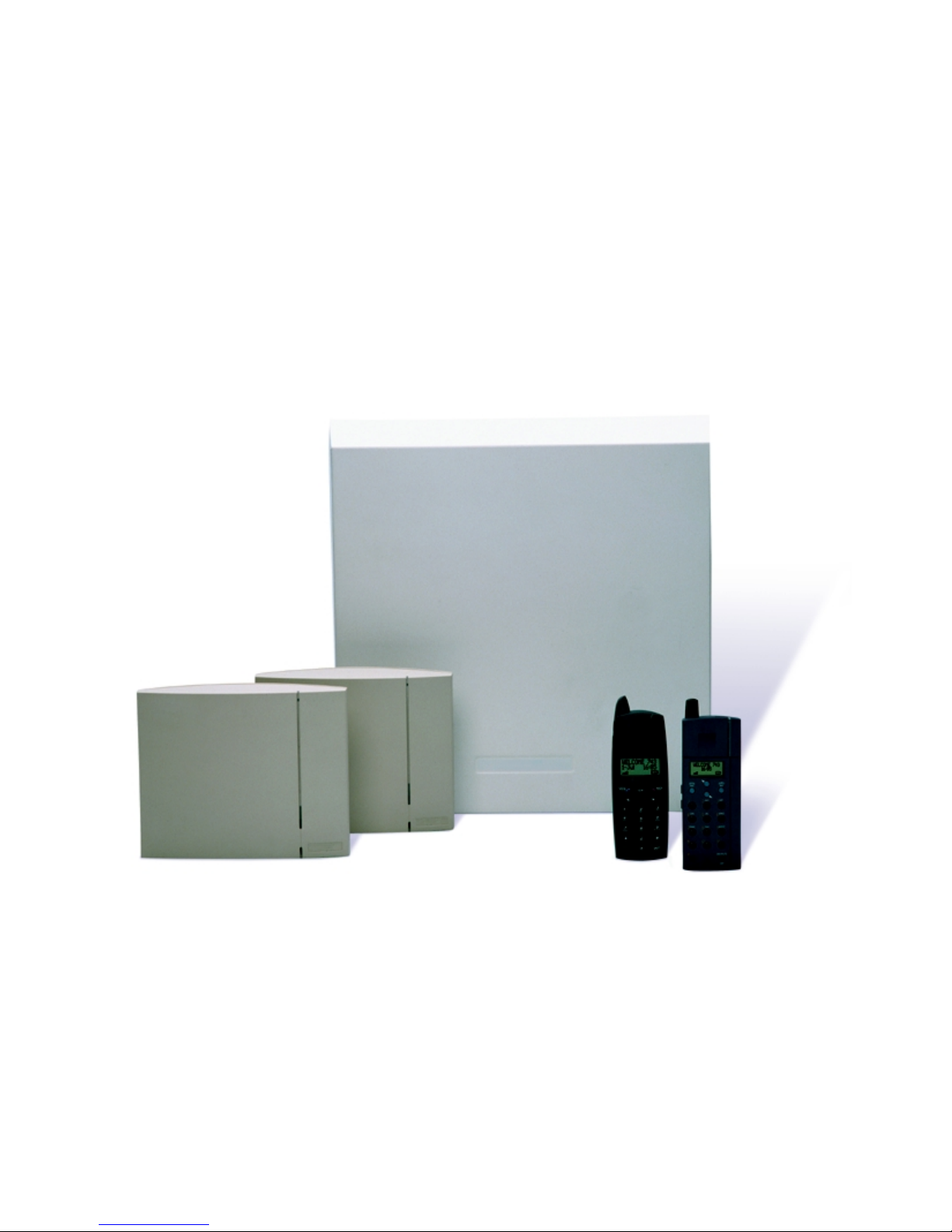
User’s Guide
DCT1800-S
DECT Business Cordless Telephone System
Page 2

Page 3

User’s Guide
DCT1800-S
Page 4

Page 5

Preface
Preface
Congratulations with the purchase of your DCT1800-S business cordless
telephone system. This system provides business cordless telephony for up to
40 users in your organisation.
This user’s guide contains all the information you need to use the cordless
telephone system.
The user’s guide gives a brief overview of the functions and possibilities of the
system. Furthermore, this guide describes how the proper functioning of the
system can be checked and problems can be fixed if these might occur.
Cordless System Manager software for Windows (optional)
To manage the cordless system, a software package is optionally available,
1
called Cordless System Manager (CSM) for Windows
describes the basic use of CSM. For a detailed description of the CSM functions,
please refer to the help file of it.
. This user’s guide
Where to find what ...
Chapter 1 Business Cordless Telephony
Overview of business cordless telephony, expansion
possibilities and safety instructions.
Chapter 2 Product overview
Brief description of the DCT1800-S system, its building
blocks and the options available.
Chapter 3 Switching the system on/off
Chapter 4 Checking the system
How to check if the system functions properly.
Chapter 5 Fixing problems
Instructions to solve eventual problems.
1. Hereinafter called CSM
5
Page 6

Preface
Chapter 6 Using CSM
A brief introduction to using the CSM software. In this
chapter you can find how to replace, add and remove
cordless phones. Furthermore, you can find how to change
date and time on the cordless system, how to make a backup
of the cordless system and how CSM can help in case of
troubles with the system.
Chapter 7 Preparing for remote maintenance
How to connect a modem and initialise it with CSM, if a
supplier wants to do remote maintenance.
Chapter 8 Technical data
Overview of accessories and ordering numbers, plus
technical specifications.
6
Page 7

Contents
Contents
Page
Chapter 1 Business Cordless Telephony ............... 11
Chapter 2 Product overview..................................... 13
2.1 Cordless system and components ............................................13
2.2 Cordless phones .......................................................................14
2.3 Base stations.............................................................................15
2.4 Radio exchange........................................................................15
2.5 Cable connections ....................................................................15
2.6 Printer (option).........................................................................16
2.7 Cordless System Manager (option)..........................................16
2.8 Accessories ..............................................................................16
Chapter 3 Switching the system on/off ................... 17
Chapter 4 Checking the system............................... 19
4.1 Checking possibilities ..............................................................19
4.2 LEDs on the radio exchange....................................................19
4.3 LEDs on the base stations........................................................20
Chapter 5 Fixing problems ....................................... 23
5.1 Fault finding.............................................................................23
5.2 System does not function at all ................................................24
5.3 Red LED radio exchange on....................................................25
7
Page 8

Contents
5.4 Complaint of one user ............................................................. 25
5.5 Complaints of more users........................................................ 26
5.6 Date and time on cordless phone not correct...........................26
5.7 Problems to be solved by the supplier.....................................26
Chapter 6 Using CSM ................................................ 27
6.1 What CSM is required for ... ................................................... 27
6.2 Preparations to use CSM .........................................................27
6.3 Working with CSM .................................................................28
6.4 Replacing a cordless phone .....................................................29
6.5 Adding a cordless phone ......................................................... 29
6.6 Removing a cordless phone.....................................................30
6.7 Change system date and time .................................................. 30
6.8 Troubleshooting with CSM..................................................... 31
Chapter 7 Preparing for remote maintenance......... 33
Chapter 8 Technical data .......................................... 37
8.1 Radio exchange ....................................................................... 37
8.2 Base station BS330-GAP ........................................................38
8.3 Base station BS340-GAP ........................................................39
8.4 LTU for DCT1800-S...............................................................40
8.4.1 LTU for DCT1800-S: CE marked version ..............................40
8.4.2 LTU for DCT1800-S: non-CE marked version....................... 40
8
Page 9

Contents
Abbreviations and glossary ........................................ 41
Index.............................................................................. 43
9
Page 10

Contents
10
Page 11

Business Cordless Telephony
Chapter 1 Business Cordless Telephony
Digital Cordless Telephone system
The DCT1800-S system is a Digital Cordless Telephone system, providing
business cordless telephony for your organisation. The DCT1800-S system
makes it possible to use cordless phones in the area covered by the system. The
user of a cordless phone can make and receive telephone calls anywhere in the
covered area. The cordless phone user can walk within the covered area while
continuing the call, with the same speech quality.
Access to the system is protected. Only cordless phones subscribed to the
system can make and receive calls. During a call nobody can eavesdrop on the
conversation.
The Digital Cordless Telephone system DCT1800-S can be connected to any
PABX (Private Automatic Branch Exchange) with analogue lines. All functions
of the PABX can be used with the cordless phones as with the fixed phones.
Once installed, the DCT1800-S system requires no user-actions unless the
system is malfunctioning. Further, it may be desired to replace, add or remove
cordless phones with the CSM software. This user’s guide gives you all
information required to perform these user tasks.
Based on international DECT-GAP standards
The DCT1800-S system is based on the international DECT standard for digital
cordless telephony. DECT stands for Digital Enhanced Cordless
Telecommunications.
The DCT1800-S system is Generic Access Profile (GAP) compliant. GAP is
another standard in DECT. Therefore the DCT1800-S system can be combined
with all DECT-GAP compliant business cordless phones.
Expanding the system
The DCT1800-S cordless system can be expanded with extra cordless phones
and extra base stations for a larger using area:
• Up to maximally 40 cordless phones can be used.
• Up to maximally 8 base stations can be used.
Your supplier will be happy to provide you with more information on the
possibilities to expand your cordless system.
11
Page 12
Business Cordless Telephony
Safety instructions
Warning
• Do not open the cordless system. This may cause
electrically unsafe situations, with danger to life.
• Never push objects of any kind through openings in the
equipment. Dangerous voltages may be present.
Conductive foreign objects could produce a short circuit
that could cause fire, electric shock or damage to the
equipment.
Warning
• Follow the instructions in this user’s guide precisely.
Performing other actions than described may cause risk
of danger or damage.
• Please contact your supplier if the system has to be
expanded, changed or re-installed.
• Note that the cordless system must remain installed in the
environment specified in chapter 8. In case of any doubt
about the environmental conditions, please contact your
supplier.
12
Page 13

Chapter 2 Product overview
2.1 Cordless system and components
The main building blocks of the DCT1800-S system are:
• Cordless phones
• Base stations
• Radio exchange
Further options are:
• Printer
Product overview
• Cordless System Manager (CSM) for Windows, a Windows
® based
software package
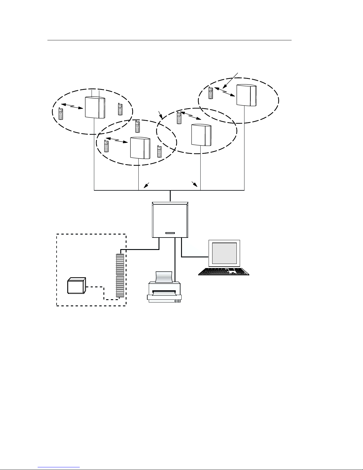
The system coverage is established by means of a network, consisting of a
number of base stations connected to the radio exchange (see figure 1).
13
Page 14
Product overview
DECT air interface
Existing equipment
PABX main
distribution
frame
Covered area
(cell)
Base station cables
Cordless
phone
DCT1800-S
radio exchange
Base
station
PC with CSM
PABX
Printer
001
Fig. 1 Overview of the DCT1800-S cordless telephone system
2.2 Cordless phones
The cordless phone gives access to all the PABX functions, using the same
codes as on a normal fixed phone. Up to maximally 40 cordless phones are
possible.
Any business cordless phone that is DECT-GAP compliant can be used.
Preferably Ericsson DECT-GAP compliant business cordless phones are used
(type DT288, DT368 etc.).
14
Page 15

Product overview
The cordless phones are connected to the base stations via a radio link.
For more information on the cordless phone and possible accessories, please
see the user’s guide of the phone or contact your supplier.
2.3 Base stations
While within range of a base station, phone calls can be made and received
with the cordless phone. Via the radio link, the base station transmits speech
data to the cordless phone and receives speech data from it.
The range of a base station depends on its type, the construction of the building
and the used materials. To allow for flexibility in coverage area, the base station
BS330-GAP with internal antennas and the BS340-GAP with external antennas
are available. Up to maximally 8 base stations can be used.
2.4 Radio exchange
The radio exchange enables data communication from the base stations to the
PABX (Private Automatic Branch Exchange) and vice versa.
Note
The DCT1800-S system can be connected directly to the PSTN (Public Switched
Telephone Network), with some restrictions that your supplier will observe. In
this guide the word PABX is used for both PABX and PSTN.
2.5 Cable connections
The radio exchange has the following cable connections:
• Mains power cable
• Cables to base stations
• Cable from radio exchange to PABX, one for each cordless phone
• Printer cable (option)
• PC cable (optional)
A modem can be connected for remote maintenance by your supplier: see
chapter 7.
15
Page 16

Product overview
2.6 Printer (option)
A printer can be connected to the radio exchange, to print service and error
messages from the cordless system.
2.7 Cordless System Manager (option)
The Cordless System Manager (CSM) is a software package to be installed on
a PC with Windows 95, Windows 98 or Windows NT 4.0.
CSM is required to:
• Add cordless phones
• Replace cordless phones
• Remove cordless phones
• Change date and time on the cordless system
• Examine the cordless system
• Generate and print service forms
• Initialise a modem for remote maintenance by a supplier
If you leave these actions to your supplier, CSM is not required.
2.8 Accessories
Your supplier standardly delivers the cordless system with:
• Power cable
• PC cable (RS232)
Optionally can be ordered:
• Printer cable
• Cordless System Manager software (CSM for Windows)
• Modem shell adapter (to connect a modem, see chapter 7)
See chapter 8 for order numbers. Please contact your supplier for more
information.
16
Page 17

Switching the system on/off
Chapter 3 Switching the system on/off
The cordless system can be switched on and off with the switch at the bottom
side of the radio exchange (see figure 1).
Switching the radio exchange on/off also switches the base stations on/off.
Once operational there is no need to switch the system off. Switching the system
off is only necessary if the system has problems.
After switching on, the system must function properly within 90 seconds, with
no red LEDs on.
Note
All current calls will be lost if the system is switched off.
Phone line
connections
Base station connectors
Printer
connector
On/off switch
l 0
PC connector
(RS232)
Power connector
016
LEDs
Fig. 2 Bottom side radio exchange with on/off switch and connectors
17
Page 18

Switching the system on/off
18
Page 19

Checking the system
Chapter 4 Checking the system
4.1 Checking possibilities
To check if the cordless system functions properly, you can inspect:
• The radio exchange LEDs (light indicators)
4.2 LEDs on the radio exchange
Figure 2 gives an overview of the LEDs at the bottom side of the radio exchange.
LED4
LED2
LED1
LED3
LED6
LED5
017
Fig. 3 Radio exchange LEDs
When the cordless system is operational, LED1 must be on (green) indicating
power on. The other LEDs must be off.
When LED2 is on (red), the cordless system has sent a message that has not
yet been read with CSM. The system may still function properly when LED2
is on.
LED3 - LED6 indicate fault situations when on (red).
19
Page 20

Checking the system
LED Normally When On Meaning Required action when on
1 On Green Power on None, normal situation
2 Off Red Message
received but not
read yet
3 - 6 Off Red Radio exchange
error
Read the message with CSM if
available.
Note that the system may continue
to function properly if only LED2
is on (red).
Try resetting the radio exchange:
switch the radio exchange off,
waiting half a minute and switching it on again.
If this does not fix the problem,
please contact your supplier.
Table 1 Meaning of radio exchange LEDs
4.3 LEDs on the base stations
Figure 3 shows the position of the two base station LEDs:
LED2
20
Front view
Fig. 4 Base station LEDs
LED1
018
Page 21

Checking the system
LEDs on base station
LED1: Green power LED (on when powered)
LED2: Three colour LED, see table 2.
Status of LED2 Meaning Required action
Off Base station operational and no
cordless phone is using the base
station
Green Base station operational and a
cordless phone is using the base
station
Red Base station is malfunctioning. Try resetting the base station:
Amber
(yellow-brown)
Flashing green 8 cordless phones are currently
Base station is OK, but not available (self-test, not initialized, no
communication with radio
exchange)
using the base station: the maximum capacity of the base station
has been reached
None
None
• By switching the radio
exchange off, waiting half a
minute and switching it on
again.
• With CSM (if available).
If the problem persists, please
contact your supplier.
None
If this frequently happens while
users having problems setting up
a call, there may be not enough
base stations. Please contact
your supplier.
Table 2 Meaning of base station LED2
21
Page 22

Checking the system
22
Page 23

Fixing problems
Chapter 5 Fixing problems
5.1 Fault finding
This chapter describes the actions the user can take if the system is not working
properly. Table 3 sums up the problems the user can solve.
Warning
Do not try to solve faults a supplier has to solve: incorrect
actions may cause danger or damage the cordless system.
Follow the instructions given in this chapter precisely.
Fault areas
Distinguish the possible fault area and go to the appropriate paragraph:
Fault area See
System does not function at all Paragraph 5.2
Red LED radio exchange on (see figure 3, page 19) Paragraph 5.3
LED2 of base station red on (see figure 4, page 20) Paragraph 4.3
Complaint of one cordless phone user Paragraph 5.4
Complaints of various cordless phone users Paragraph 5.5
Problems with cordless phone User’s guide cordless
phone
Cordless phone is lost, and may be misused. See chapter 6.6 (CSM
required).
Date and time on cordless system and cordless phones
are not correct.
See paragraph 5.6
(CSM required)
Table 3 Fault finding areas
Fault finding procedures are described in a Go/No-Go way. Each question can
be answered with Yes or No. Depending on the answer either take the action
described, or continue the procedure. If ‘Continue’ is followed by a number,
jump to that number. Otherwise continue at the next question.
23
Page 24

Fixing problems
Resetting the cordless system
In case of problems, you can try resetting the cordless system:
• Switch off the system, waiting half a minute and switch it on again.
• Or reset using CSM (if available).
After a reset, the system must function properly within 90 seconds, with no red
LEDs on.
Note
When resetting the system, all current calls will be lost.
Tip
CSM (if available) can give a detailed overview of the cordless system.
5.2 System does not function at all
1. Is the green power LED1 on the radio exchange on? (See
figure 3, page 19.)
Ye s: System is powered. Try another fault area: see paragraph 5.1.
No: Continue.
2. Is the radio exchange switched on with the power switch?
Ye s: Continue.
No: Switch it on.
3. Is the power cable connected properly to the mains socket and the radio
exchange?
Ye s: Continue
No: Connect the power cable properly.
4. Is power present on the mains socket?
Ye s: Contact your supplier.
No: Problem is in the mains.
24
Page 25

Fixing problems
5.3 Red LED radio exchange on
1. Is only LED2 on?
Ye s: The system may function properly. This LED indicates that a
message from the cordless system has not yet been read with CSM.
If the system does not function properly, continue.
No: Continue.
2. Reset the entire cordless system, with the on/off switch or CSM (if
available). After a reset, the system must function properly within 90
seconds, with no red LEDs on. Is any red LED still on 90 seconds after
resetting?
Ye s: Continue.
No: System is OK now.
3. Are all cables connected properly (see figure 2, page 17)?
Ye s: Contact your supplier.
No: Try connecting the cables. If this does not help, contact your
supplier.
5.4 Complaint of one user
1. Cordless phone shows normal display? (See cordless phone user’s guide.)
Ye s: Continue.
No: See the cordless phone user’s guide.
2. Go off hook, in the vicinity of a base station. Do you hear a dial tone?
Ye s: Continue.
No: Try going off hook again, the base station may be overloaded
(LED2 on base station is flashing green). If still no dial tone is
heard, continue.
3. Do other cordless phones give a dial tone when off hook?
Ye s: Cordless phone is defective. Replace the cordless phone, see
chapter 6.4.
No: Contact your supplier.
25
Page 26

Fixing problems
5.5 Complaints of more users
1. Are the complaints (bad speech quality, calls being blocked) coming from
a specific area?
Ye s: Check the functioning of the base stations (check the base station
LEDs, see paragraph 4.3). If a base station is malfunctioning, try
resetting the cordless system. If this does not help, contact your
supplier.
No: Continue.
2. Is any of LED3 - LED6 on the radio exchange on?
Ye s: Try resetting the system. After a reset, the system must function
properly within 90 seconds, with no red LEDs on. If after a reset
any of LED3 - LED6 remains on (red), contact your supplier.
No: Contact your supplier.
5.6 Date and time on cordless phone not correct
Use CSM (if available) to set date and time on the cordless system. Otherwise,
please contact your supplier.
5.7 Problems to be solved by the supplier
If any of the following problems occurs, please contact your supplier:
• The cordless system does not function at all, although it is switched on
and powered properly.
• Any of LED3 - LED6 on the radio exchange remains on (red), even after
a reset.
• A base station keeps malfunctioning, with a LED red on, even after
resetting the cordless system.
• Various cordless phone users have problems making calls.
• Other problems that cannot be solved with the instructions from 5.1 to 5.6.
26
Page 27

Using CSM
Chapter 6 Using CSM
6.1 What CSM is required for ...
Once the DCT1800-S system has been installed by your supplier, no further
actions have to be taken. It is possible to make phone calls right away.
CSM is required to:
• Replace, add and remove cordless phones: see paragraph 6.4 to 6.6.
• Change date and time on the cordless system: see paragraph 6.7.
• Investigate the cordless system in case of troubles, and generate and print
service forms: see paragraph 6.8.
• Initialise a modem for remote maintenance by a supplier: see chapter 7.
If you leave these actions to your supplier, CSM is not required.
6.2 Preparations to use CSM
1. Install the CSM software on a PC with Windows 95, Windows 98 or
Windows NT 4.0 (see the installation instructions supplied with it).
2. Connect the PC with CSM to the radio exchange with the PC cable
(RS232) that is delivered to the cordless system (see figure 5, page 28).
27
Page 28

Using CSM
Fig. 5 PC connector at bottom side radio exchange
l 0
016
PC connector
(RS232)
3. Start the CSM software.
4. Set the right COM port and baud rate for communication with the cordless
system. Supported baud rates are 2400, 4800 and 9600 baud.
5. Establish the connection to the cordless system.
6.3 Working with CSM
To work with CSM, use both the functions in the menu bar and the windows.
For example, if you want to subscribe a cordless phone first establish a
connection, then select the window ‘Cordless Phones’ and finally choose the
option ‘Subscribe Cordless Phone’ from the ‘Cordless Phone’ menu.
For more information, please see the help file of CSM.
Tip
Instead of using the menu bar, you can often use the right mouse button too.
Clicking on the right mouse button often displays a pop-up menu.
Note
CSM has password-protected functions. These are special functions for your
supplier (distributor).
28
Page 29

Using CSM
6.4 Replacing a cordless phone
To replace a cordless phone, for example when it is defective:
1. Cancel the subscription of the defective cordless phone in CSM: use the
‘Delete Subscription’ option in the ‘Cordless Phone’ menu.
2. Another cordless phone can be subscribed to the same extension number.
Use the ‘Subscribe Cordless Phone’ option in the ‘Cordless Phone’ menu
and fill in the IPEI number of the cordless phone.
3. Subscribe the cordless phone (see the user’s guide of the cordless phone).
4. It is recommended to make a new backup of the cordless system data: use
the ‘System Backup’ option in the ‘File’ menu. Your supplier can restore
this backup in case of serious system troubles.
Note
When the subscription has been cancelled, you can subscribe another cordless
phone to the same extension number.
6.5 Adding a cordless phone
The cordless system needs to know which cordless phones are in use. Before
a cordless phone can be used, it must be subscribed to the cordless system.
Note
Adding a cordless phone is only possible if there are free line connections
between PABX and the cordless system. If there are no free line connections
any more, please contact your supplier.
To add a cordless phone with CSM:
1. Select an extension number and use the ‘Subscribe Cordless Phone’ option
in the ‘Cordless Phone’ menu.
2. It is recommended to make a new backup of the cordless system data: use
the ‘System Backup’ option in the ‘File’ menu. Your supplier can restore
this backup in case of serious system troubles.
29
Page 30

Using CSM
6.6 Removing a cordless phone
If a cordless phone is no longer used, it is better to prevent misuse and remove
it from the cordless system.
To remove a cordless phone from the cordless system:
1. Cancel the subscription of the cordless phone: use the ‘Delete
Subscription’ option in the ‘Cordless phone’ menu.
2. It is recommended to make a new backup of the cordless system data: use
the ‘System Backup’ option in the ‘File’ menu. Your supplier can restore
this backup in case of serious system troubles.
Note
Do not use the ‘Delete Extension Number’ option to remove a cordless phone.
If an extension number is deleted, the line connection between PABX and
cordless system is terminated. As a result, it is not possible to use that line with
a cordless phone. If somehow an extension number has been deleted, see the
CSM help file to add the extension number(s) again.
6.7 Change system date and time
In some cases it is necessary to change the date and time of the clock on the
DCT1800-S by using the ‘Change Date/Time’ option in the ‘System’ menu.
These date and time are displayed on the cordless phones connected to the
system.
For example, changing date and time is necessary when changing to daylight
saving time and back.
30
Page 31

Using CSM
6.8 Troubleshooting with CSM
CSM gives a detailed overview of the cordless system and its status. You can
check the status of the cordless system and the service messages.
Create a service form
With the ‘Create Service Form’ option in the ‘File’ menu, service forms can
be printed or saved as a file. These service forms are useful for your supplier
in case of problems.
Reset system and unit
With the ‘Reset System’ option in the ‘System’ menu, the complete
DCT1800-S system can be reset. The separate units in the radio exchange and
the base stations can also be reset, using the ‘Reset’ option in the ‘Board’ or
‘Base Station’ menu.
Note
When resetting the entire cordless system, all calls will be lost. When resetting
a unit, only the calls using that unit will be lost.
31
Page 32

Using CSM
32
Page 33

Preparing for remote maintenance
Chapter 7 Preparing for remote
maintenance
Modem connection
Your supplier can perform remote maintenance on the cordless system by a
modem connection.
The modem can be connected to the radio exchange with the Modem shell
adapter (RNTNB 102 109) and the PC (RS232) cable. The Modem shell
adapter connects with a 9 pins connector to the RS232 cable. At the other side
it has a 25 pins connector, to which a modem can be connected (see figure 6).
PC modem
cable
Remote PC
CSM side
Note: The CSM side modem can also be an internal PC modem
Analogue
telephone line
CSM side
modem
Modem shell adapter
(RNTNB 102 109)
System side
modem
System side
PC cable
(TSRNB 101 22)
Cordless system
DCT1800-S
026
Fig. 6 Remote maintenance configuration
With CSM you can initialise the modem on the side of the cordless system for
remote maintenance of the cordless system.
Note
In case of troubles with the modem, see the accompanying documentation.
Initialising the system side modem with CSM
1. Determine the baud rate of the cordless system.
If necessary you can check the baud rate as follows:
a. Connect the PC with CSM to the cordless system.
b. Check the baud rate setting of the cordless system with the
‘Connection Settings’ option in the ‘System’ menu.
c. Disconnect the CSM software from the cordless system.
33
Page 34

Preparing for remote maintenance
2. Disconnect the PC cable from the cordless system.
3. Connect the PC with a PC cable to the modem, see figure 7.
PC modem cable
PC with CSM
System side
modem
027
Fig. 7 PC initialising system side mode
4. Switch on the modem.
5. Initialise the system side modem with CSM in the ‘Too ls ’ menu with the
option ‘Initialise System Side Modem’:
a. Select the COM port of the modem.
b. Set the baud rate of the cordless system.
c. In case of non-standard modems, you can change the AT commands
that will be sent to the modem by clicking the ‘Advanced’ button (see
the CSM help file).
6. Disconnect the PC cable from the modem.
7. Connect the modem to the cordless system, with the Modem shell adapter
and the PC cable (see figure 6).
8. Connect the modem to an analogue telephone line.
9. Check that the modem is on.
The cordless system is now ready for remote maintenance.
Installing the CSM side modem
1. If you use an external modem, connect the CSM side modem to COM1
or COM2 of the remote PC with the PC modem cable.
2. Make sure that CSM is installed on the remote PC.
34
Page 35

Preparing for remote maintenance
3. If you use an external modem, switch on the CSM side modem.
4. Start CSM and choose from the ‘To ols ’ menu the option ‘Manage Remote
Systems’. Follow then the instructions of the CSM help file.
35
Page 36

Preparing for remote maintenance
36
Page 37

Technical data
Chapter 8 Technical data
8.1 Radio exchange
Product number
NTM/CNHNB 301 04/x
Compliance to European regulations and standards
CE marking :
European Council Directives : 91/263/EEC, Telecommunications Terminal
Directive
: 73/23/EEC, Low Voltage Directive
: 89/336/EEC, Electromagnetic Compatibility
Directive (EMC)
: 93/68/EEC, CE Marking Directive
DECT : TBR10, TBR22
Safety : EN 60950
EMC : ETS 300 329, EN 61000-3-2, EN 61000-3-3
Compliance to non-European regulations and standards
Applicable standards dependent on sales area
Safety : IEC 950, AS/NZS 3260, ACA TS001
Note
The combination of radio exchange and interface boards complies with the
regulations and standards mentioned.
Environmental
Temperature
Operating : 0 to +40
Storage :
Relative humidity : 20 to 80%, non condensing
General specifications
Width x depth x height : 421 x 186 x 417 mm
Weight : ca. 10 kg (with 5 LTU boards added)
Power consumption : max. 100 W
Housing material : zinc plated steel sheet
Colour of cabinet : RAL 9010
−40 to +70 °C
°C
37
Page 38

Technical data
Application information : for indoor use only, wall mounted
Enclosure class : IP 20
Number of LTU boards : up to max. 5
Number of cordless phones : up to max. 40
Number of base stations : up to max. 8
Distance to base station : up to max. 1.9 km
Required free space around :
above : min. 0.2 m
to the left and to the right: min. 0.1 m
below : min. 0.3 m
Supported baud rate : 2400, 4800 and 9600 baud
Accessories and spare parts
RS232 cable (PC cable) : TSRNB 101 22
Modem shell adapter : RNTNB 102 109
Printer cable : TSRNB 101 23
Power cable : RPMNB 101 03/x
CSM (for Windows, softw.) : LZYNB 201 50/n
8.2 Base station BS330-GAP
Product number : KRCNB 301 xx/n
Compliance to European regulations and standards
CE marking :
0344
European Council Directives : 91/263/EEC, Telecommunications Terminal
Directive
: 73/23/EEC, Low Voltage Directive
: 89/336/EEC, Electromagnetic Compatibility
Directive (EMC)
: 93/68/EEC, CE Marking Directive
DECT : TBR6, TBR22
Safety : EN 60950, CENELEC CLS/SC111B,
ENV 50166-2
EMC : ETS 300 329
: EN 55022 class B
: EN 61000-4-5 (DC ports: 2 kV common
mode, 1 kV differential mode)
: EN 61000-4-2 (15 kV air discharge, 8 kV
contact discharge)
38
Page 39

Technical data
Compliance to non-European regulations and standards
Applicable standards dependent on sales area
Safety : ANSI/IEEE C95.1, IEC 950, AS/NZS 3260,
ACA TS001
EMC : ITU-T Recommendation K.20, ACA TS006
Environmental
Application : for indoor use only
Temperature
Operating :
−10 to +55 °C
Storage :
−40 to +70 °C
Relative humidity
Operating : 15 to 90%, non condensing
Storage : 5 to 95%, non condensing
General specifications
Powering method : via 2 data pairs (unshielded twisted pairs) or
1 EPP, depending on distance between base
station and radio exchange
Width x depth x height : 200 x 165 x 56 mm (incl. mounting bracket)
Weight : 470 grams
Colour cover : light grey
Operating voltage : 21 to 56 Vdc
Power consumption : 3.0 W typical, 5 W maximum
Radio specifications
Frequency band : 1880 to 1900 MHz
8.3 Base station BS340-GAP
Product number : KRCNB302 0x/1
General specifications
Size standard antenna : 107 (l) x 8.5 (d) mm
Weight standard antennas : 17 grams
Other specifications
For all other specifications refer to paragraph 8.2
39
Page 40

Technical data
8.4 LTU for DCT1800-S
8.4.1 LTU for DCT1800-S: CE marked version
Product number : RTM/ROFNB 101 72/2
Compliance to European regulations and standards
CE marking :
0560
European Council Directives : 98/13/EC, Telecommunications Terminal
Equipment and Satellite Earth Station
Equipment
: 93/68/EEC, CE Marking Directive
PSTN attachment : TBR21
: All applicable Advisory Notes of the
Analogue Type Approval Advisory Board
(dependent on sales area).
Compliance to non-European regulations and standards
Applicable standards dependent on sales area
Transmission performance : ITU-T Recommendation G.712
8.4.2 LTU for DCT1800-S: non-CE marked version
Product number : RTM/ROFNB 101 72/1
Compliance to non-European regulations and standards
Applicable standards dependent on sales area
Transmission performance : ITU-T Recommendation G.712
40
Page 41

Abbreviations and glossary
Abbreviations and glossary
CSM : Cordless System Manager for Windows
Windows based software to set up and examine the
cordless system.
DCT : Digital Cordless Telephony
DECT : Digital Enhanced Cordless Telecommunications
Standard for cordless telecommunication.
GAP : Generic Access Profile
Communication protocol standard within DECT, that
guarantees compatibility of systems and components.
LED : Light Emitting Diode
LTU : Line Termination Unit
Interface board that connects cordless system and
PAB X.
PABX : Private Automatic Branche eXchange
Telephone exchange.
PSTN : Public Switched Telephone Network
The public telephone network.
41
Page 42

Abbreviations and glossary
42
Page 43

Index
Index
access 11
accessories
adding a cordless phone
base station
function
LEDs
cable connections
calling problem
change date and time
checking the system
base station LEDs
radio exchange LEDs
connectors radio exchange
cordless phone
adding
lost
removing
replacing
Cordless System Manager
see CSM
16
CSM
change date and time
connection
date and time
DCT1800-S
access
base stations
building blocks
connection
cordless phones
CSM
options
printer
radio exchange
16
29
13
15
20
15
21, 26
30
19
20
15
29
30
30
29
27
30
11
11
15
13
11
13, 15
27
13
13
15
19
17
30
DECT
eavesdropping
environmental conditions
expanding system
fault areas
fixing problems
GAP
inspecting
LEDs
modem connection
Modem shell adapter
options
ordering numbers
PABX
printer
problems
11
11
base station
radio exchange
39
37
11
23
23
11
base station LEDs
radio exchange LEDs
base station
radio exchange
20
20
19
33
33
16
37
11
16
complaint of one user
complaints of more users
contact dealer required
cordless phone lost
fault areas
LED basestation red
23
30
19
25
26
26
21
43
Page 44

Index
LED radio exchange red 25
system does not function
unable to set up a call
radio exchange
function
LEDs
removing a cordless phone
replacing a cordless phone
24
reset
with CSM
13
15
19
31
21
30
29
24
service form
switching on/off
system expansion
technical data
troubleshooting
see problems
unable to set up call
31
17
11
37
21
44
Page 45

Page 46

For further information please contact:
EN/LZTNB 101 168/1 R2
© 1999
Subject to change without prior notice
 Loading...