

Ericsson AXX 9100 CONNECT Quick Reference Manual

AXX 9100 CONNECT
R1.2
Quick Reference Guide

Copyright
© Ericsson AXXESSIT AS - All rights reserved
Disclaimer
No part of this document may be reproduced in any form without the written
permission of the copyright owner.
The contents of this document is subject to revision without notice due to
continued progress in methodology, desig and manufacturing. Ericsson shall
have no liability for any error or damage of any kind resulting from the use of
this document.

AXX 9100 CONNECT R1.2 Quick Reference Guide
3/1531-ZAP 701 14/1 Uen A 2006-10-16
1 INSTALLATION OF AXX 9100 CONNECT
1.1 PRE-INSTALLATION PROCEDURES 1
1.1.1 Shipment verification 1
1.1.2 Preliminary inventory check 1
1.1.3 Reporting damage 1
1.2 SITE PREPARATION 1
1.3 UNPACKING 2
1.3.1 Unpack the AXX 9100 CONNECT base unit 3
1.3.2 Unpack the AXX 9100 CONNECT Service modules 4
1.4 INSTALLATION 4
1.4.1 Installation Overview 5
1.4.2 Installation Planning 5
1.4.3 Installation Guidelines 7
1.4.4 Grounding Considerations 7
1.4.5 Power Interfaces 8
1.5 AXX 9100 CONNECT INSTALLATION 8
1.5.1 Mount the AXX 9100 CONNECT in a rack 9
1.5.2 Requirements to Installation Locations 10
1.6 INSTALLATION OF POWER 11
1.6.1 Install the – 48 VDC Power 13
1.6.2 Install external ground 14
1.6.3 Install the –AC 230V Power Adaptor 15
1.7 INSTALLATION OF SERVICE MODULES 16
1.7.1 General 16
1.7.2 Available service modules 17
1.7.3 Hot insertion and removal 19
1.8 INTERCONNECTIONS AND CABLE HANDLING 20
1.8.1 Power cables 20
1.8.2 Alarm cable 21
1.8.3 VT-100 cable 21
1.8.4 LAN cables 21
1.8.5 E1 cables 21
1.8.6 E3/T3 21
1.8.7 Management cable 21
1.8.8 Synchronization cable 22
1.8.9 AUX Port cable 22
1.8.10 Fibre cables 22
1.8.11 Installing Electrical Cables 22

AXX 9100 CONNECT R1.2 Quick Reference Guide
3/1531-ZAP 701 14/1 Uen A 2006-10-16
1.9 SFP MODULES 24
1.9.1 Introduction 24
1.9.2 Installation of SFP Modules 25
1.9.3 Installing and removing SFP modules 26
1.9.4 Connecting to SFP modules 29
1.9.5 Cleaning fibre-optic connectors 30
2 CONFIGURATION OF AXX 9100 CONNECT
2.1 INITIAL CONFIGURATION 33
2.1.1 Commissioning of IP address via VT100 Interface 33
2.1.2 Configure Community-handler 36
2.1.3 Assign an IP-address to the AXX 9100 CONNECT 37
2.1.4 Change Passwords 38
2.1.5 Erase a Community string 39
2.2 SET UP CONNECTION TO A NETWORK ELEMENT 39
2.3 SYSTEM MODE FROM IP TO IP UN-NUMBERED 41
2.3.1 Products affected 41
2.3.2 Problem description 41
2.3.3 Problem symptoms 41
2.3.4 Workaround 42
2.4 FURTHER CONFIGURATION 44
2.4.1 Recommended order 44
2.4.2 Further reading 44

1
3/1531-ZAP 701 14/1 Uen A 2006-10-16
AXX 9100 CONNECT R1.2 Quick Reference Guide
1 Installation of AXX 9100 CONNECT
1
1.1 Pre-Installation Procedures
This section provides pre-installation procedures for the
AXX 9100 CONNECT.
1.1.1 Shipment verification
When the AXX 9100 CONNECT equipment is received, please
verify that the shipment is according to order.
NOTE! Ship equipment from one site to another in the original
packing including the antistatic bags.
NOTE! Keep the AXX 9100 CONNECT system equipment in the
original shipping containers if storage is required. Storage
more than 12 months is not recommended. The equipment
should be stored in a ventilated and static-safe location.
1.1.2 Preliminary inventory check
Verify that the packing list information is equal to the information
provided on the shipping labels. Please notify contact resource to
your support if any discrepancies must be reported.
1.1.3 Reporting damage
Damage to shipped articles must be reported to contact resource.
1.2 Site Preparation
Verify that the installation site meets the following criteria:
AXX 9100 CONNECT R1.2 Quick Reference Guide
3/1531-ZAP 701 14/1 Uen A 2006-10-16
2
• The site conforms to all environmental specifications
• The floor or mounting area where you will install the equipment
can support the equipment.
NOTE! The following tables are based on typical AXX 9100
CONNECT system configurations and may vary in specific
customer configurations.
1. Power supply for the AXX 9100 CONNECT equipment must be
available as described in
Table 1
2. Power consumption for the AXX 9100 CONNECT equipment
must be supported as described in
Table 1
3. Circuit breakers for the AXX 9100 CONNECT equipment must be
according to
Table 1
4. Recommended clearance for accessing the AXX 9100
CONNECT equipment during and after installation must be as
described in
Table 2 :
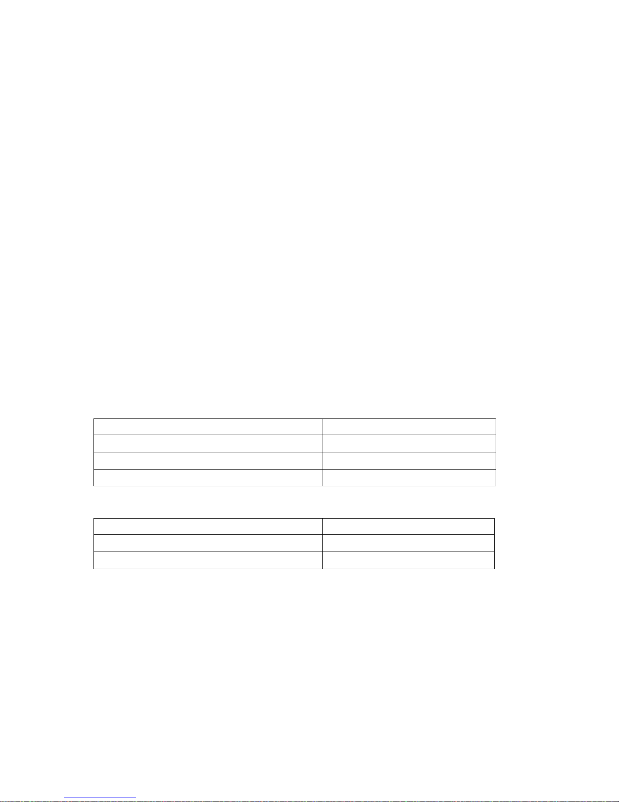
Table 1 Power Supply Requirements
Table 2 Recommended Access Clearance
1.3 Unpacking
When unpacking and storing AXX 9100 CONNECT equipment:
• Leave equipment packed until it is needed for immediate
installation.
• Store packed equipment in a ventilated and static-safe location
Equipment Type Power Supply Requirements
-48 V DC - 48 VDC; -36 to -72 V DC
Power consumption capability 50 W
Circuit breaker requirement 2 A
Item Recommended Clearance
Bay access needed for maintenance Front access only, 500 mm
Back clearance to bays (if necessary) 300 mm
3
3/1531-ZAP 701 14/1 Uen A 2006-10-16
AXX 9100 CONNECT R1.2 Quick Reference Guide
• Store the packaging material in case the equipment must be reshipped.
NOTE! Stored anti-static bags will degrade after approximately 6
months.
• If the packaging and/ or equipment is damaged, preserve as
much of the packaging as possible for shipment and damage
analysis.
• Report damage to shipped articles to dedicated contact resource
1.3.1 Unpack the AXX 9100 CONNECT base unit
This section contain specific instructions for unpacking AXX 9100
CONNECT system equipment.
Caution!
When opening a subrack container, use caution to avoid
damaging the contents.
Caution!
Wear a grounding wrist strap while unpacking, handling and
interconnecting the AXX 9100 CONNECT equipment modules, to
discharge any static buildup.
1. Open the top of the cardboard shipping container.
2. Take the box containing the AXX 9100 CONNECT accessory kit
out of the shipping container.
3. Lift the AXX 9100 CONNECT out of the packaging box and
remove the anti-static bag and foam inserts.
AXX 9100 CONNECT R1.2 Quick Reference Guide
3/1531-ZAP 701 14/1 Uen A 2006-10-16
4
1.3.2 Unpack the AXX 9100 CONNECT Service
modules
Caution!
When opening a module container, use caution to avoid
damaging the contents.
Caution!
Wear a grounding wrist strap while unpacking,handling and
interconnecting the AXX 9100 CONNECT equipment modules, to
discharge any static buildup.
1. Open the container and remove the module(s) and packing
material.
2. Carefully remove anti-static bag from the module(s).
1.4 Installation
This section provides instructions before installing AXX 9100
CONNECT unit.
NOTE! The instructions in this section primarily address the
installation of the AXX 9100 CONNECT, and modules
supplied by Ericsson AXXESSIT AS. Codes and regulations
for installing racks, electrical wiring, raceways, and other
equipment is not covered in this manual,
Caution!
Wear a grounding wrist strap while unpacking,handling and
interconnecting the AXX 9100 CONNECT equipment modules, to
discharge any static buildup.

5
3/1531-ZAP 701 14/1 Uen A 2006-10-16
AXX 9100 CONNECT R1.2 Quick Reference Guide
1.4.1 Installation Overview
You should be thoroughly familiar with the instructions in this
manual before starting any work. Use the following general order of
work when installing a site:
1. Read and observe all safety cautions and warnings.
2. When you arrive at the site, first verify the AXX 9100 CONNECT
equipment according to the procedures in
“Pre-Installation
Procedures” on page 1 -1. If there is a problem with the
equipment, use the dedicated contact resources for your support
3. If you do not install the equipment when it arrives, store as
specified in
“Pre-Installation Procedures” on page 1 -1
4. Unpack equipment only after preparing the site as described in
“Pre-Installation Procedures” on page 1 -1
5. When installing equipment at a site, follow the procedures in this
chapter in the order presented.
6. Make connections using the information in “Interconnections and
cable handling” on page 1 -20
1.4.2 Installation Planning
Based on the system to be installed, determine the size, number,
and location of racks, as well as the AXX 9100 CONNECT requires.
The AXX 9100 CONNECT will fit in 19-in. equipment racks, and can
be adapted for ETSI racks. The racks must be accessible from the
front and rear for equipment installation.
NOTE! Recommended space of rear access for installation of the
equipment is 300 mm.
AXX 9100 CONNECT R1.2 Quick Reference Guide
3/1531-ZAP 701 14/1 Uen A 2006-10-16
6
Caution!
When installing in an environment where compliance to safety
standard ETS/EN 60950 is required, consider the following:
If not all interconnections can be classified as SELV, the
equipment shelf must only be installed in Restricted Area
Location (RAL) and be permanent connected to safety-ground
via rack or separate ground.
An additionally national requirement apply for Norway, Sweden
and Finland; this equipment must only be inst alled in Restricte d
Area Location (RAL) and be permanent connected to
equipotential bonding.
All interconnected equipment and shielded cabling must be
connected to the same ground potential.
The interfaces cables (especially E1 interfaces) must not run in
the same pipes as the power cables
Plan rack and unit installation based on the following
considerations:
• Install the lowest unit in a rack first. (Recommended clearance
between two units is 50 mm.)
• Determine wire size based on cable length and local engineering
standards and practices.
• Plan the power cable from the power distribution panel (PDP) to
units, proceeding down along the right side of the equipment
rack.
• Plan grounding cable runs from the ground window down along
the right side of the rack to the units.
• Plan to route the electrical cables to and from the units along the
right side of the rack to the overhead cable transport tray.
• Plan to route the optical cables to and from the units along the left
side of the rack to the overhead cable transport tray.
1.4.2.1 Recommended items
To install an AXX 9100 CONNECT system, customary installation
and electrical tools are required. The following items are also
recommended:

7
3/1531-ZAP 701 14/1 Uen A 2006-10-16
AXX 9100 CONNECT R1.2 Quick Reference Guide
• Multimeter
• Pozidrive screwdriver (PZ3, PZ) to attach the AXX 9100
CONNECT to the rack and to attach the brackets to the AXX
9100 CONNECT,
• Phillips (PH3) as an alternative screwdriver
• Allen wrench
• Yellow green flexible ground cable (1.25 - 2.50 mm2, 16 - 14
AWG)
• 1.25mm lint-free swabs (preferably clean room quality)
• Video fiber connector inspection instrument
• Caps for optical connectors
• Plugs for optical adapters
•Tie wraps
1.4.3 Installation Guidelines
When installing AXX 9100 CONNECT equipment into racks, follow
these guidelines:
• Consider the effect of additional electronic equipment and its
generated heat on the AXX 9100 CONNECT system equipment.
• Make sure the equipment rack is properly bolted to the ground
and, if required, to the ceiling.
• Ensure that the weight of the equipment does not make the rack
unstable.
• When mounting the equipment between two posts or rails,
ensure that the minimum clearance between the sides is 19 “.
• Maintain a minimum clearance of 500 mm in front of the
equipment and 300 mm at the back of the equipment.
1.4.4 Grounding Considerations
We recommend a proper grounding of the AXX 9100 CONNECT
independent on safety requirements. The AXX 9100 CONNECT
may be connected to ground with the yellow/green wire in the power
AXX 9100 CONNECT R1.2 Quick Reference Guide
3/1531-ZAP 701 14/1 Uen A 2006-10-16
8
cable (pin on power connector marked GND), or by permanently
connection of the chassis to ground.
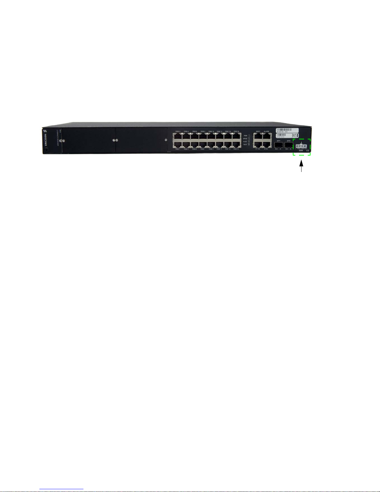
For location of the power connector on the AXX 9100 CONNECT,
see Figure 1
Figure 1 Location of the power connector on the AXX 9100 CONNECT
1.4.5 Power Interfaces
The AXX 9100 CONNECT DC-power interface comply with
ETSI/EN 300 132-2, with a nominal source voltage of -48VDC or 60VDC. This covers the a voltage range from -40VDC to -72VDC.
If installed outside a RAL, use a power source with a maximum
voltage of -60VDC.
1.5 AXX 9100 CONNECT Installation
Use the following procedures to install the AXX 9100 CONNECT in
an equipment rack.
When installing the AXX 9100 CONNECT, you can also use the
extension brackets, included in the AXX 9100 CONNECT accessory
kit, to convert a 19-inch rack to a ETSI rack.
NOTE! 1U is 44.45 mm.
9
3/1531-ZAP 701 14/1 Uen A 2006-10-16
AXX 9100 CONNECT R1.2 Quick Reference Guide
Caution!
Wear a grounding wrist strap while unpacking,handling and
interconnecting the AXX 9100 CONNECT equipment modules, to
discharge any static buildup.
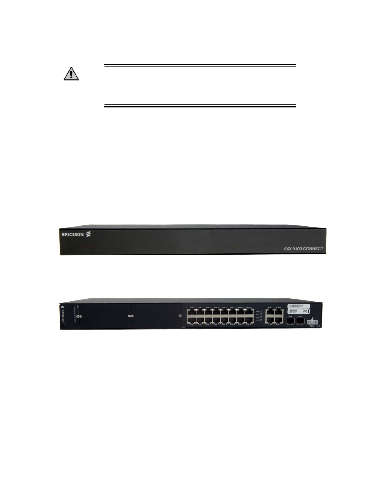
1.5.1 Mount the AXX 9100 CONNECT in a rack
Decide which side do you want to use as the front sid e (you can use
the side with the connectors or the Ericsson AXXESSIT branded
side as the front side) depends on if you have back access.
See Figure 2 and Figure 3
Figure 2 Branded side of the AXX 9100 CONNECT
Figure 3 Connector side of AXX 9100 CONNECT
1. Using attached screws, install the brackets on the left and right
side.
2. Move the AXX 9100 CONNECT to the desired rack position.
3. Align four M6 cage nuts in the equipment rack with the mounting
holes on the front of the AXX 9100 CONNECT.

AXX 9100 CONNECT R1.2 Quick Reference Guide
3/1531-ZAP 701 14/1 Uen A 2006-10-16
10
4. Align the AXX 9100 CONNECT with the equipment rack and
cage nuts.
5. Insert the AXX 9100 CONNECT into the equipment rack.
6. Connect the AXX 9100 CONNECT to the equipment rack with
four M6 screws.
1.5.2 Requirements to Installation Locations
1.5.2.1 Installation in Restricted Access Location (RAL)
When installed in a telecommunication centre, the AXX 9100
CONNECT must be properly mounted in a grounded rack with
brackets or in other ways properly connected to safety ground. The
AXX 9100 CONNECT DC power source must not be located outside
the RAL.
1.5.2.2 Installation outside Restricted Access Location
If installed outside a RAL area, the AXX 9100 CONNECT - 48V DC
power source and all communication inte rfac es conn ected must
comply to SEL V circuit s require ments. The -48V DC power must not
exceed -60V DC, and must be powered from an certified AC to DC
power supply unit or a battery unit.
1.5.2.3 Definitions
Restricted Access Location (RAL)
A location for equipment where both of the following paragraphs
apply:
• access can only be gained by service persons or by users who
have been instructed about the reasons for the restrictions
applied to the location and about any precautions that shall be
taken; and
• access is through the use of a Tool or lock and key, or other
means of security, and is controlled by the authority responsible
for the location.
SELV Circuits
SELV Circuits are ports that have maximum DC working voltage
level less than 60Volt (42.4V AC). In addition, the ports must not be
connected to telecommunication networks in the EN 60950 meaning

11
3/1531-ZAP 701 14/1 Uen A 2006-10-16
AXX 9100 CONNECT R1.2 Quick Reference Guide
of the term (see CEI/ IEC 60950-1 2001-10 standard clause
1.2.13.8).
In practice, the electrical cables shall not exit the building. In
addition, the electrical cables shall connect to equipment that eit her:
• are installed in RAL or
• shall not have electrical cables that exits the building unless
those ports are TNV circuits or
• shall have a written consent or in other ways evident that its
connecting port towards the SELV circuit port is not a
telecommunication network.
Telecommunication Network
A metallically terminated transmission medi um inte nded for
communication between equipment that may b e located in sepa rate
buildings, excluding:
• the mains system for supply, transmission and distribution of
electrical power, if used as a telecommunication transmission
medium;
• Cable Distribution System;
• SELV Circuits connecting units of information technology
equipment.
TNV Circuit
A circuit which is in the equipment and to which the accessible area
of contact is limited and that is so designed and protected that,
under normal operating conditions and single fault conditions (see
CEI/IEC 60950-1 2001-10 standard clause 1.4.14), the voltages do
not exceed specified limit values.
1.6 Installation of Power
This section consists of procedures to explain how to install AXX
9100 CONNECT power connections.
Please follow the safety prec aut ions when installing or removing
any of the power modules.
 Loading...