

Page 1

AP 6321 Quick Install Guide
QUICK GUIDE
1/006 92-LZA 101 822 Uen D
Page 2

Copyright
© Ericsson AB 2013. All rights reserved. No part of this document may be
reproduced in any form without the written permission of the copyright owner.
Disclaimer
The contents of this document are subject to revision without notice due to
continued progress in methodology, design and manufacturing. Ericsson shall
have no liability for any error or damage of any kind resulting from the use
of this document.
Trademark List
®
Wi-Fi
Wi-Fi Certified logo
Ericsson
Wi-Fi®is a registered trademark of the Wi-Fi Alliance.
The Wi-Fi CERTIFIED logo is a registered trademark
of the Wi-Fi Alliance.
Ericsson is the trademark or registered trademark of
Telefonaktiebolaget LM Ericsson. All other product or
service names mentioned in this manual are trademarks
of their respective companies.
1/006 92-LZA 101 822 Uen D | 2013-11-08
Page 3
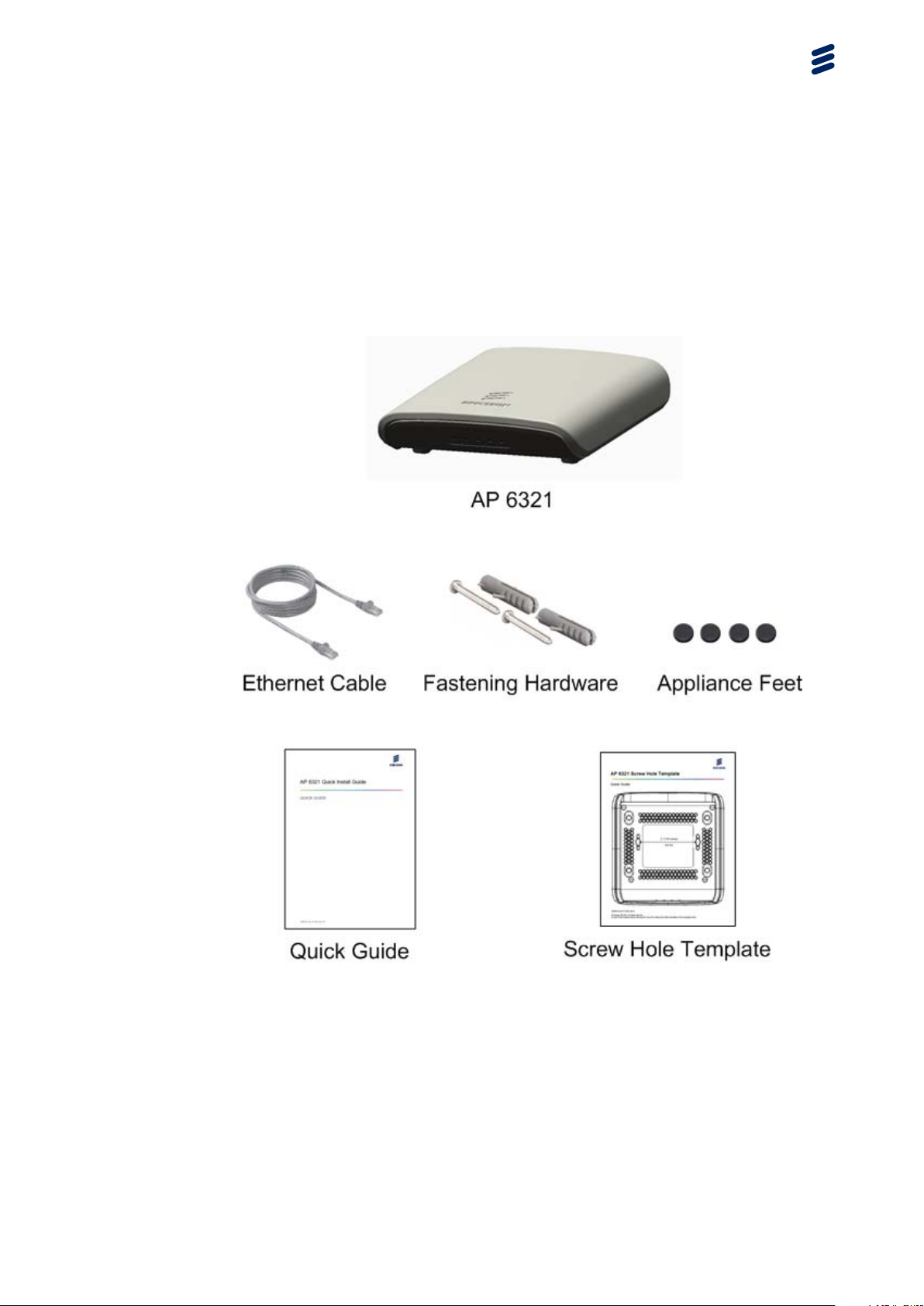
1 Getting Started
1.1 Package Contents
Getting Started
Note: Ericsson also offers the following options, which are ordered and
shipped separately:
• AC Power Adapter
• Ceiling Tile Hanger Kit
• Passive PoE Injector
1/006 92-LZA 101 822 Uen D | 2013-11-08
2
Page 4
AP 6321 Quick Install Guide
Contact your Ericsson representative for more information.
1.2 Unit Description
1.2.1 Power Connector
The unit does not have a power switch. It is powered on when connected
to a power source. The power adapter, ordered and shipped separately,
automatically adjusts to any voltage between 100~240 volts at 50 Hz or 60 Hz.
The unit draws up to 0.43 A at 48 V DC (20.9 W).
Warning!
The AC Power Adapter relies on the rated fuse or circuit breaker of the wall
outlet (15 A in North America, 10 A in Europe).
Use ONLY the Ericsson power adapter for the AP 6321. Use of any other
power adapter can damage the unit and voids the Ericsson product warranty.
1.2.2 Internet Port
Table 1 shows the power consumption for the Internet port.
Table 1 Power Consumption Table
State
Internet Port
Only
Caution!
Internet Port
and One LAN
Port
Internet Port
and Four LAN
Ports
Idle 5.6 W 6.3 W 8.4 W
Medium Traffic 12 W 12.7 W 14.9 W
High Traffic 16 W 16.7 W 18.9 W
Maximum Traffic 18 W 18.7 W 20.9 W
The PoE switch or power injector must meet local and national regulatory
requirements.
3
1/006 92-LZA 101 822 Uen D | 2013-11-08
Page 5

Getting Started
802.3at Power Source Equipment (PSE) Specification:
• 50.0 to 57 V DC, with 30 W output power from the PSE
802.3at Powered Device (PD) Specification:
• 42.5 to 57 V DC at the PD, with 25.5 W maximum input power to the PD
802.3at Cable Specification:
• 100 m maximum length
• Maximum cable pair resistance of 12.5 Ohms, satisfied by using CAT5
or CAT5e as specified by ANSI/TIA/EIA-568 or Class D as specified by
ISO/IEC 11801:1995
• 600 mA maximum current per pair
1.2.3 Reset Button
This button is used to restore the factory default configuration using a paperclip
or pen tip. Hold down the button for 15 seconds or more, until all of the
indicators turn off, to remove any configuration changes and restore the unit
to the factory default configuration.
1/006 92-LZA 101 822 Uen D | 2013-11-08
4
Page 6
AP 6321 Quick Install Guide
2 Installing the AP 6321
2.1 Step 1—Select Location
Choose a proper place for the unit. In general, the best location is at the
center of the intended wireless coverage area, within line of sight of all wireless
devices. For optimum performance, consider these guidelines:
• Mount the unit as high as possible above any obstructions in the coverage
area.
• Avoid mounting next to or near building support columns or other
obstructions that can cause reduced signal or null zones in parts of the
coverage area.
• Mount away from any signal absorbing or reflecting structures (such as
those containing metal).
The unit can be mounted on any horizontal surface, on a wall or from a hanging
ceiling.
The unit is UL2043 Certified for Plenum mounting. Installers must use Plenum
rated Ethernet cable for installations in the environmental air space of a
building, such as above suspended ceilings. Installers must follow local and
national codes for above ceiling installations.
Warning!
Do not install the unit in any areas where blasting (blasting caps, radio
controlled equipment) or explosive gases can be present.
Warning!
The unit, its AC power adapter, and its cables are not designed for outdoor
use. They must be located indoors.
5 1/006 92-LZA 101 822 Uen D | 2013-11-08
Page 7

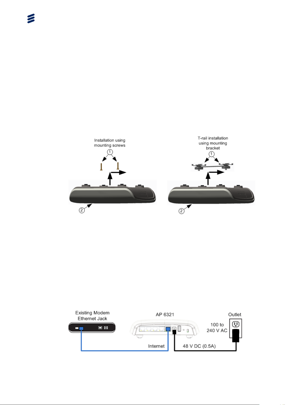
2.2 Step 2—Mount on a Flat Surface
Mount the unit only on a flat surface that is at least 1/2-inch (12.7-mm) plywood
or the equivalent. To mount the unit on a ceiling or a wall, use one of the
following options:
• To mount the unit on a wall or on a ceiling that does not have T-rails, use
the pan head Phillips screws provided with the unit.
• To mount the unit on a ceiling that has T-rails, use either a T-rail mounting
bracket or the pan head Phillips screws provided with the unit. T-rail
mounting brackets are included in the Ceiling Tile Hanger Kit (BNCKG0158
or INE 105 3079), which can be ordered separately. The Ceiling Tile
Hanger Kit includes five T-rail mounting brackets and five sets of four
appliance feet.
To mount the unit using the mounting screws provided with the unit, do the
following:
Installing the AP 6321
1. Attach the mounting screws to a ceiling or wall.
• Use the included Screw Hole Template as a guide.
• For concrete or brick walls, drill holes and use the included nylon wall
plugs.
• For T-rail installations, drill 3/32-inch (2.4-mm) pilot holes.
• Leave a 5/16-inch (8-mm) gap so the unit can slide over the screw
heads.
2. Attach the appliance feet provided with the unit to the unit.
3. Attach the unit to the mounting screws by doing the following:
a Line up the two mounting slots on the bottom of the unit with the two
mounting screws.
b Slide the unit across into position so that the mounting screws support
the unit.
c Adjust the screw depth as required so that there is a snug fit between
the unit and the mounting screws.
To mount the unit using a T-rail mounting bracket, do the following:
1. Clip the T-rail mounting bracket to a T-rail.
2. Attach the correct appliance feet to the unit:
• For a suspended ceiling with recessed T-rails (this is a ceiling in which
the tiles hang below the T-rails), attach the appliance feet provided
with the unit.
1/006 92-LZA 101 822 Uen D | 2013-11-08
6
Page 8
AP 6321 Quick Install Guide
• For a suspended ceiling in which the tiles are flush with the T-rails,
attach the appliance feet provided in the Ceiling Tile Hanger Kit.
3. Attach the unit to the mounting points on the mounting bracket by doing
the following:
a Line up the two mounting slots on the bottom of the unit with the two
mounting points on the mounting bracket.
b Slide the unit across into position so that the mounting points support
the unit.
2.3 Step 3—Connect and Power On
The AP 6321 can get its operating power directly from either of the following
sources:
• An AC wall outlet
• The Internet port when connected to a device that provides IEEE 802.3at
compliant Power over Ethernet (PoE)
If the AP 6321 is connected to both a PoE source device and an AC power
source, AC is disabled.
Figure 1 Wall Outlet Power
7
1/006 92-LZA 101 822 Uen D | 2013-11-08
Page 9

Installing the AP 6321
Caution!
Use ONLY the Ericsson power adapter for the AP 6321. Use of any other
power adapter can damage the unit and voids the Ericsson product warranty.
Figure 2 Power over Ethernet
Warning!
If PoE is used, the AP 6321 must be connected to a power source that complies
with IEEE 802.3at, or to an IEC/EN 60950-1 compliant power limited source.
2.4 Step 4—Check Indicators
All indicators are illuminated for about one to two seconds when the unit is
powered on. After powering on, wait 2 minutes and check that the indicators on
the unit match the indicators in Table 2.
Table 2 Indicator Behavior
Indicator Behavior
(FAULT)
Off
81/006 92-LZA 101 822 Uen D | 2013-11-08
Page 10

AP 6321 Quick Install Guide
Indicator Behavior
(OPERATIONAL)
2.4G Green
5G Green
(INTERNET)
If the indicator behavior does not match Table 2, refer to the AP 6321 Technical
Description, 1/1550-LZA 101 822 for detailed indicator descriptions.
2.5 Step 5—Configure Unit
In most cases, the unit configures itself automatically after powering on. To
configure the unit manually through its local web interface or Command Line
Interface (CLI), refer to the Access Point User Guide, 1/1553-LZA 101 806.
Green
Green
9
1/006 92-LZA 101 822 Uen D | 2013-11-08
Page 11

AP 6321 Conformity and Regulatory
Statements
STATEMENT OF COMPLIANCE
1/174 02-LZA 101 822 Uen C
Page 12

Copyright
© Ericsson AB 2013. All rights reserved. No part of this document may be
reproduced in any form without the written permission of the copyright owner.
Disclaimer
The contents of this document are subject to revision without notice due to
continued progress in methodology, design and manufacturing. Ericsson shall
have no liability for any error or damage of any kind resulting from the use
of this document.
Trademark List
®
Wi-Fi
Wi-Fi Certified Logo
Ericsson
Wi-Fi®is a registered trademark of the Wi-Fi Alliance.
The Wi-Fi CERTIFIED logo is a registered trademark
of the Wi-Fi Alliance.
Ericsson is the trademark or registered trademark of
Telefonaktiebolaget LM Ericsson. All other product or
service names mentioned in this manual are trademarks
of their respective companies.
1/174 02-LZA 101 822 Uen C | 2013-11-25
Page 13

Contents
Contents
1 About this Document 1
1.1 Scope 1
1.2 Target Group 1
1.3 Comments About the Documentation 1
2 Regulatory Information and Disclaimers 2
3 Manufacturer’s US Federal Communication
Commission Conformity Statement 3
3.1 FCC Interference Statement 3
3.2 FCC Radiation Exposure Statement 4
4 Manufacturer’s Industry Canada Conformity Statement 5
5 Manufacturer’s European Community Conformity
Statement 7
6 Declaration of Conformity for RF Exposure 9
7 Product Disposal 10
7.1 Mise au rebut du produit 10
7.2 Produktentsorgung 10
7.3 Verwijdering van het product 10
7.4 Tuotteen hävittäminen 11
7.5 Smaltimento del prodotto 11
7.6 Produktbortskaffelse 11
7.7 Eliminação do produto 11
7.8 Eliminación del producto 11
1/174 02-LZA 101 822 Uen C | 2013-11-25
Page 14

1 About this Document
This section describes the scope and target groups for this document.
1.1 Scope
This document provides the regulatory information, disclaimers, and compliance
statements for the product.
1.2 Target Group
The information in this document is intended for all personnel who want to
learn more about the product.
About this Document
1.3 Comments About the Documentation
Ericsson encourages you to provide feedback, comments or suggestions so
that we can improve the documentation to better meet your needs. With your
comments provide the following:
• Document title
• Document number and revision
• Page number or section number
Please send your comments to your local Ericsson Support.
1/174 02-LZA 101 822 Uen C | 2013-11-25
1
Page 15

AP 6321 Conformity and Regulatory Statements
2 Regulatory Information and Disclaimers
Installation and use of this device must be in strict accordance with the
instructions included in the user documentation provided with the product.
Any changes or modifications to this product not expressly approved by the
party responsible for compliance could void the user’s authority to operate
this equipment.
The manufacturer is not responsible for any interference to radio or television
equipment caused by unauthorized modification of this device, or attachment
of any antennas or equipment other than those specified by the manufacturer.
The manufacturer or its authorized resellers or distributors will assume no
liability for any damage arising from failure to comply with these guidelines, or
failure to comply with local, regional or national safety, electrical or building
codes, or government regulations.
This product is manufactured in China with originating and non-originating
product.
Ce produit est fabriqué en Chine avec des matières originaires et non
originaires du produit.
This device contains the following: FCC ID: RAR40065006; IC:
4674A-40065006 (AP 6321).
2
1/174 02-LZA 101 822 Uen C | 2013-11-25
Page 16

Manufacturer’s US Federal Communication Commission Conformity Statement
3 Manufacturer’s US Federal Communication
Commission Conformity Statement
This device complies with Part 15 of the FCC Rules.
Operation is subject to the following two conditions (1) this device may not
cause harmful interference, and (2) this device must accept any interference
received, including interference that may cause undesired operation.
3.1 FCC Interference Statement
This equipment has been tested and found to comply with the limits for a
Class B digital device, pursuant to Part 15 of the FCC Rules. These limits
are designed to provide reasonable protection against harmful interference
in a residential installation. This equipment generates, uses and can radiate
radio frequency energy and, if not installed and used in accordance with
the instructions, may cause harmful interference to radio communications.
However, there is no guarantee that interference will not occur in a particular
installation. If this equipment does cause harmful interference to radio or
television reception, which can be determined by turning the equipment off
and on, the user is encouraged to try to correct the interference by one of the
following measures:
• Reorient or relocate the receiving antenna.
• Increase the separation between the equipment and receiver.
• Connect the equipment into an outlet on a circuit different from that to which
the receiver is connected.
• Consult the dealer or an experienced radio/TV technician for help.
FCC Caution: Any changes or modifications not expressly approved by the
party responsible for compliance could void the user’s authority to operate
this equipment.
This device complies with Part 15 of the FCC Rules. Operation is subject to the
following two conditions: (1) This device may not cause harmful interference,
and (2) this device must accept any interference received, including interference
that may cause undesired operation.
For product available in the USA/Canada market, at 2.4 GHz, only channel 1-11
can be selected. Selection of other channels is not possible.
This device and its antenna(s) must not be co-located or operating in
conjunction with any other antenna or transmitter except in accordance with
FCC multi-transmitter product procedures.
1/174 02-LZA 101 822 Uen C | 2013-11-25
3
Page 17

AP 6321 Conformity and Regulatory Statements
Operation of this device in the 5.15-5.25 GHz frequency range is restricted
to indoor environments only.
Note: Country code selection is for non-US models only and is not available
to US models. Per FCC regulations, all Wi-Fi products marketed in the
US are fixed to US operating channels only.
3.2 FCC Radiation Exposure Statement
This equipment complies with FCC radiation exposure limits set forth for an
uncontrolled environment. This equipment should be installed and operated
with minimum distance 9.8 inches (25 cm) between the radiator and your body.
4
1/174 02-LZA 101 822 Uen C | 2013-11-25
Page 18

Manufacturer’s Industry Canada Conformity Statement
4 Manufacturer’s Industry Canada Conformity
Statement
This device complies with Industry Canada license-exempt RSS standard(s).
Operation is subject to the following two conditions: (1) this device may not
cause interference, and (2) this device must accept any interference, including
interference that may cause undesired operation of the device.
For product available in the USA/Canada market, at 2.4 GHz, only channel 1-11
can be selected. Selection of other channels is not possible.
This device and its antenna(s) must not be co-located or operating in
conjunction with any other antenna or transmitter except in accordance with IC
multi-transmitter product procedures.
Caution:
The device for the band 5150-5250 MHz is only for indoor usage to reduce
potential for harmful interference to co-channel mobile satellite systems.
IMPORTANT NOTE:
Radiation Exposure Statement:
This equipment complies with IC RSS-102 radiation exposure limits set forth for
an uncontrolled environment. This equipment should be installed and operated
with minimum distance 25 cm between the radiator and your body.
Le présent appareil est conforme aux CNR d'Industrie Canada applicables
aux appareils radio exempts de licence. L'exploitation est autorisée aux deux
conditions suivantes : (1) l'appareil ne doit pas produire de brouillage, et (2)
l'utilisateur de l'appareil doit accepter tout brouillage radioélectrique subi, même
si le brouillage est susceptible d'en compromettre le fonctionnement.
Pour les produits disponibles aux États-Unis / Canada du marché, seul le canal
1 à 11 peuvent être exploités. Sélection d'autres canaux n'est pas possible.
Cet appareil et son antenne (s) ne doit pas être co-localisés ou fonctionnement
en association avec une autre antenne ou transmetteur.
Avertissement:
Les dispositifs fonctionnant dans la bande 5150-5250 MHz sont réservés
uniquement pour une utilisation à l’intérieur afin de réduire les risques de
brouillage préjudiciable aux systèmes de satellites mobiles utilisant les mêmes
canaux.
1/174 02-LZA 101 822 Uen C | 2013-11-25
5
Page 19

AP 6321 Conformity and Regulatory Statements
NOTE IMPORTANTE:
Déclaration d'exposition aux radiations:
Cet équipement est conforme aux limites d'exposition aux rayonnements
IC établies pour un environnement non contrôlé. Cet équipement doit être
installé et utilisé avec un minimum de 25 cm de distance entre la source de
rayonnement et votre corps.
6
1/174 02-LZA 101 822 Uen C | 2013-11-25
Page 20

Manufacturer’s European Community Conformity Statement
5 Manufacturer’s European Community
Conformity Statement
Table 1 European Community Conformity Statement
Language Statement
English This equipment is in compliance with the essential
requirements and other relevant provisions of Directive
1999/5/EC.
Deutsch Dieses Gerät entspricht den grundlegenden Anforderungen
und den weiteren entsprecheneden Vorgaben der Richtlinie
1999/5/EU.
Dansk Dette udstyr er i overensstemmelse med de væsentlige krav
og andre relevante bestemmelser i Directiv 1999/5/EF.
Español Este equipo cumple con los requisitos esenciales asi como
con otras disposiciones de la Directiva 1999/5/EC.
Français Cet appareil est conforme aux exigences essentielles et aux
autres dispositions pertinentes de la Directive 1999/5/EC.
Íslenska
Italiano Questo apparato conforme ai requisiti essenziali ed agli altri
Nederlands Deze apparatuur voldoet aan de belangrijkste eisen en
Norsk Dette utstyret er i samsvar med de grunnleggende krav og
Português Este equipamento satisfaz os requisitos essenciais e outras
Suomalainen Tämä laite täyttää direktiivin 1999/5/EY oleelliset vaatimukset
Svenska Denna utrustning är i överensstämmelse med de väsentliga
Þessi búnaður samrýmist lögboðnum kröfum og öðrum
ákvæðum tilskipunar 1999/5/ESB.
principi sanciti dalla Direttiva 1999/5/EC.
andere voorzieningen van richtlijn 1999/5/EC.
andre relevante bestemmelser i EU-directiv 1999/5/EC.
provisões da Directiva 1999/5/EC.
ja on siinä asetettujen muidenkin ehtojen mukainen.
kraven och andra relevanta bestämmelser i Direktiv
1999/5/EC.
The Declaration of Conformity related to this product can be found by contacting
Ericsson.
The AP 6321 complies with the following R&TTE Radio standards:
• EN 300 328 v1.8.1 (2012-06) Electromagnetic compatibility and Radio
Spectrum Matters (ERM); Wideband transmission systems; Data
1/174 02-LZA 101 822 Uen C | 2013-11-25
7
Page 21

AP 6321 Conformity and Regulatory Statements
transmission equipment operating in the 2,4 GHz ISM band and using
wide band modulation techniques; Harmonized EN covering the essential
requirements of article 3.2 of the R&TTE Directive.
• EN 301 893 v1.7.1 (2012-06) Broadband Radio Access Networks (BRAN);
5 GHz high performance RLAN; Harmonized EN covering the essential
requirements of article 3.2 of the R&TTE Directive.
The AP 6321 complies with the following R&TTE EMC standards:
• EN 301 489-1 v1.9.2 (2011-09) Electromagnetic compatibility and Radio
spectrum Matters (ERM); ElectroMagnetic Compatibility (EMC) standard
for radio equipment and services; Part 1: Common technical requirements.
• EN 301 489-17 v2.2.1 (2012-09) ElectroMagnetic Compatibility and Radio
Spectrum Matters (ERM); ElectroMagnetic Compatibility (EMC) Standard
for Radio Equipment; Part 17: Specific Conditions for Broadband Data
Transmission Systems.
The AP 6321 complies with the following R&TTE Safety standards:
• EN 50385:2002 Product standard to demonstrate the compliance of radio
base stations and fixed terminal stations for wireless telecommunication
systems with the basic restrictions or the reference levels related to human
exposure to radio frequency electromagnetic fields (110 MHz - 40 GHz) General public.
• EN 62311:2008 Assessment of electronic and electrical equipment related
to human exposure restrictions for electromagnetic fields (0 Hz - 300 GHz).
• EN 60950-1:2006 (+A11:2009+A1:2010+A12:2011) Information technology
equipment - Safety - Part 1: General requirements.
The following CE mark is affixed to the AP 6321:
Note: This equipment is intended to be used in all EU and EFTA countries.
Outdoor use may be restricted to certain frequencies and/or may
require a license for operation – for example in France the frequencies
2454-2483.5 MHz are restricted to 10 mW effective isotropic radiated
power (EIRP) in outdoor environments, so channels 8-13 require
reduced power. For more details, contact Ericsson.
8
1/174 02-LZA 101 822 Uen C | 2013-11-25
Page 22

Declaration of Conformity for RF Exposure
6 Declaration of Conformity for RF Exposure
This Wireless LAN radio device has been evaluated under Health Canada
Safety Code 6 and EN 62311:2008, and found to be compliant to the
requirements set forth in CFR 47 Sections 2.1091, 2.1093, and 15.247 (b) (4)
addressing RF exposure from radio frequency devices. This Wireless LAN
radio device also conforms to EU Health and Safety Directive 2004/40/EC
as per EN 50385.
This device complies with FCC RF radiation exposure limits for an uncontrolled
environment. The radiated output power of this Wireless LAN device is below
the FCC radio frequency exposure limits. However, this device should still
be installed and used in such a manner that the potential for human contact
during normal operation is minimized.
This device and its antenna(s) must not be co-located or operating in
conjunction with any other antenna or transmitter except in accordance with
FCC multi-transmitter product procedures.
The availability of some specific channels and/or operational frequency bands
are country dependent and are firmware programmed at the factory to match
the intended destination. The firmware setting is not accessible by the end user.
1/174 02-LZA 101 822 Uen C | 2013-11-25
9
Page 23

AP 6321 Conformity and Regulatory Statements
7 Product Disposal
Ericsson adheres to directive 2002/96/EC of the European Parliament and
the council of 27 January 2003 on Waste Electrical and Electronic Equipment
(WEEE).
To dispose of equipment, including batteries, contact Ericsson customer service
to get a Return Material Authorization (RMA) number and shipping instructions.
7.1 Mise au rebut du produit
Ericsson se conforme à la directive 2002/96/EC du Parlement européen et du
Conseil de l’Europe du 27 janvier 2003 relative à la destruction des déchets
d’équipements électriques et électroniques (DEEE).
Si vous souhaitez vous débarrasser de l’équipement, y compris des piles,
veuillez communiquer avec le service à la clientèle de Ericsson, afin d’obtenir
un numéro d’autorisation de retour du matériel et des instructions sur les
modalités d’expédition.
7.2 Produktentsorgung
Ericsson erfüllt die Anforderungen der Richtlinie 2002/96/EG des
Europäischen Parlaments und des Rates vom 27. Januar über Elektro- und
Elektronik-Altgeräte (Waste Electrical and Electronic Equipment = WEEE).
Für die Entsorgung von Geräten, einschließlich Batterien, wenden Sie
sich bitte an den Kundendienst von Ericsson, um eine RMA-Nummer
(Rücksendenummer) und die Versandanweisungen zu erhalten.
7.3 Verwijdering van het product
Ericsson volgt Richtlijn 2002/96/EG van het Europese Parlement en de Raad
van 27 januari 2003 betreffende afgedankte elektrische en elektronische
apparatuur (AEEA).
Voor het verwijderen van apparatuur, met inbegrip van batterijen, neemt u
contact op met Ericsson klantenservice voor een retournummer (RMA) en
verzendinstructies.
10
1/174 02-LZA 101 822 Uen C | 2013-11-25
Page 24

7.4 Tuotteen hävittäminen
Ericsson noudattaa sähkö- ja elektroniikkalaiteromusta 27 päivänä tammikuuta
2003 annettua Euroopan parlamentin ja neuvoston direktiiviä 2002/96/EY.
Palauttaaksesi välineet, mukaan luettuina akut, ota yhteys Ericsson
–asiakaspalveluun, niin saat RMA (Return Material Authorization) –numeron
ja lähetysohjeet.
7.5 Smaltimento del prodotto
Ericsson aderisce alla direttiva 2002/96/CE del parlamento Europeo e del
Consiglio d’Europa del 27 gennaio 2003, sullo smaltimento degli apparecchi
elettrici ed elettronici (WEEE).
Per lo smaltimento di tali apparecchi, comprese le batterie, contattare
l’assistenza clienti di Ericsson per ottenere un numero di autorizzazione alla
restituzione del materiale da smaltire (Return Material Authorization - RMA) e le
istruzioni per la spedizione.
Product Disposal
7.6 Produktbortskaffelse
Ericsson overholder direktivet 2002/96/EC fra Europa-Parlamentet og -Rådet
dateret den 27. januar 2003 om Waste Electrical and Electronic Equipment
(WEEE) (Affald af elektrisk og elektronisk udstyr).
For at bortskaffe udstyr, samt batterier, kontakt kundeservicen hos
Ericsson for at få et Return Material Authorization (RMA)-nummer
(returneringstilladelsesnummer) og forsendelsesinstruktioner.
7.7 Eliminação do produto
A Ericsson cumpre a Directiva 2002/96/CE do Parlamento Europeu e do
Conselho, de 27 de Janeiro de 2003, relativa aos Resíduos de Equipamentos
Eléctricos e Electrónicos (REEE).
Para proceder à eliminação do equipamento, incluindo as baterias, é favor
contactar a assistência ao cliente da Ericsson para obter um número de
Autorização de Devolução do Material (RMA – Return Material Authorization) e
as instruções relativas ao envio.
7.8 Eliminación del producto
Ericsson cumple con la directiva 2002/96/EC del Parlamento Europeo y del
Consejo de 27 de enero de 2003 sobre los residuos de aparatos eléctricos y
electrónicos (RAEE).
1/174 02-LZA 101 822 Uen C | 2013-11-25
11
Page 25

AP 6321 Conformity and Regulatory Statements
Para la eliminación de equipo, incluyendo las pilas, contacte con el servicio de
atención al cliente de Ericsson y obtenga el número de una Autorización de
Devolución de Material (RMA) y las instrucciones para la expedición.
12
1/174 02-LZA 101 822 Uen C | 2013-11-25
 Loading...