

Ericsson ALLEGRA EDACS Maintenance Manual

AE/LZB 119 1645 R1B
Printed in U.S.A.
Maintenance Manual
ALLEGRA - EDACS
®
800 MHz DUPLEX PORTABLE
ericssonz
Ericsson Inc.
Private Radio Systems
Mountain View Road
Lynchburg, Virginia 24502
1-800-528-7711 (Outside USA, 804-528-7711)
NOTICE!
This manual covers Ericsson and General Electric products manufactured and sold by Ericsson Inc.
NOTICE
Repairs to this equipment should be made only by an authorized service technician or in a facility designated by the supplier. Any
repairs, alterations or substitutions of recommended parts made by the user to this equipment not approved by the manufacturer
could void the user’s authority to operate the equipment in addition to the manufacturer’s warranty.
NOTICE!
The software contained in this device is copyrighted by Ericsson Inc. Unpublished rights are reserved under the copyright
laws of the United States.
This manual is published by Ericsson Inc., without any warranty. Improvements and changes to this manual necessitated by typographical errors, inaccuracies of
current information, or improvements to programs and/or equipment, may be made by Ericsson Inc., at any time and without notice. Such changes will be
incorporated into new editions of this manual. No part of this manual may be reproduced or transmitted in any form or by any means,. Electronic or mechanical,
including photocopying and recording, for any purpose, without the express written permission of Ericsson Inc.
Copyright May 1995, Ericsson Inc.
TABLE OF CONTENTS
Page
SPECIFICATIONS*.........................................................................................................................................................2
DESCRIPTION.................................................................................................................................................................2
RELATED MANUALS ................................................................................................................................2
OPTIONS AND ACCESSORIES ....................................................................................................................................2
PROGRAMMABLE FEATURES ...........................................................................................................................2
OTHER PROGRAMMABLE FEATURES............................................................................................................2
CONTROLS AND INDICATORS ...................................................................................................................................3
OPERATION..................................................... .. .. .. .. .................................... .. .. .. .................................... .. .. .. .. ..................3
CIRCUIT DESCRIPTION................................................................................................................................................3
LOGIC BOARD.......................................................................................................................................................3
Microprocessor..............................................................................................................................................3
Modem ASIC .................................................................................................................................................3
Flash Prom Circuitry.....................................................................................................................................3
I2 C Device Interface ....................................................................................................................................4
Bertram IC Interface......................................................................................................................................4
Synthesizer I nterface.......................................................... ...........................................................................4
ASP Interface.............................................. .................................................. .................................................4
Keyboard Interface........................................................................................................................................4
Battery Power Control Circuits.....................................................................................................................4
Receive Audio ........................... .......... .......... .......... .......... .......... .......... .......... .......... .......... .......... .......... ......4
Transmit Audio ..............................................................................................................................................5
TABLE OF CONTENTS - CONTINUED
Page
RF BOARD ..............................................................................................................................................................5
Power Distribution ........................................................................................................................................5
Transmitter:....................................................................................................................................................5
Tx-Synthesizer:..............................................................................................................................................5
Rx-Synthesizer:.............................................................................................................................................5
Receiver .........................................................................................................................................................6
SERVICE SECTION.........................................................................................................................................................6
CARE OF EQUIPMENT................................................................................................................. ........................6
SERVICE & TROUBLESHOOTING..............................................................................................................................6
LOGIC BOARD TEST PROCEDURE...................................................................................................................6
Test Fixtures: ................................................................................................................. ................................6
Reference Drawings......................................................................................................................................6
Visual Inspection: ..........................................................................................................................................6
POWER-UP:..................................................................................................................................................6
Flash Program Code:.....................................................................................................................................6
Initiate Test Mode: .........................................................................................................................................6
MEMORY TESTS: ...........................................................................................................................................................8
AUDIO TESTS: ................................................................................................................................................................8
DISPLAY TEST: ...............................................................................................................................................................8
KEYBOARD TEST:.........................................................................................................................................................8
ELECTROSTATIC DEVICES .........................................................................................................................................8
DISASSEMBLY AND REASSEMBLY...........................................................................................................................8
Disassembly ................................................................................. ..................................................................8
Reassembly .......................... ..........................................................................................................................8
BATTERY REMOV AL AND INSTALLATION......... ... ... .. .... .. .... .. .... .. .... .. .... .. ... ... .. .... .. .... .. .... .. .... .. .... .. ... ... .. .... .. .... .. .... .9
Standard Battery Removal and Insertion......................................................................................................9
High Capacity Battery Removal and Insertion.............................................................................................9
SMD COMPONENT REMOVAL AND REPLACEMENT...................................................................................9
PROGRAMMING THE RADIO......................................................................................................................................9
SERVICING THE BATTERY....................................................................................................................... .. .................9
PARTS LIST
LOGIC BOARD .......................................................................................................................................................15
RF BOARD ..............................................................................................................................................................16
MISCELLANEOUS PARTS....................................................................................................................................17
PRODUCTION CHANGES.............................................................................................................................................17
IC DATA DIAGRAMS
IC Data, Logic Board ....................................................................................................................................10
IC Data, RF Board.........................................................................................................................................14
ASSEMBLY DIAGRAMS
RADIO ASSEMBLY................................................................................................................................................17
LOGIC BOARD .......................................................................................................................................................18
RF BOARD ..............................................................................................................................................................21
SCHEMATIC DIAGRAMS
LOGIC BOARD .......................................................................................................................................................18
RF BOARD ..............................................................................................................................................................21
REVISION HISTORY
REVISION DATE REASON FOR CHANGE
R1A 5/96 Original issue.
R1B 1/96 Correct parts on Parts List and schematics. Revision Letter changes to RF Board.
AE/LZB 119 1645 R1B
1

DESCRIPTION
This manual contains essential information needed to main-
tain the Ericsson ALLEGRA EDACS
®
800 MHz Duplex Portable radio. Included in this manual is a brief description of the
radio, troubleshooting and alignment information, radio disassembly and reassembly procedures, battery replacement and
disposal procedures, and circuit descriptions.
The ALLEGRA Duplex Portable radio is synthesized, microprocessor based, high performance duplex portable FM radio. Operation in the 800 MHz frequency range this radio
provides reliable two-way radio communications in EDACS
environments. The ALLEGRA EDACS radio is available in two
models: Interconnect only or Interconnect/Dispatch. A wide
variety of options and accessories are available.
Duplex operation is provided in EDACS systems while
operation in the Telephone Interconnect mode. At all other
times, the radio operates in the half-duplex mode, i.e. when
placing group calls in the EDACS environments.
Advanced state- of- the -art technology is used in the design
and manufacture of this synthesized radio to provide the most
in flexibility, capability, and adaptability to various system
configurations. This flexibility allows the user to have the
operation of his radio customized or tailored (by programming)
to satisfy his needs by activating the desired features. The
ALLEGRA is small, compact, lightweight, yet ruggedly constructed to provide reliable service.
RELATED MANUALS
Operator’s Manual........................................ AE/LZT 123 1872
Installation, Vehicle Handsfree .................... AE/LZT 123 1874
User’s Guide, Vehicle Handsfree ................. AE/LZT 123 1873
EDACS II Programming Software...............................TQ3373
Programming Cable............................................RPM 113 1460
OPTIONS AND ACCESSORIES
DYCH5B Rapid Multi-Charger, 120 VAC (for high and
ultra high capacity batteries)
DYCH5D Rapid Travel Charger, 12 Vdc
DYCF1F Power Adapter, 1 2 VDC
DYMC5V Portable Handsfree (includes microphone
and earpiece
DYMN7A Vehicle Handsfree Installation Package
DYPA5Z High Capacity Battery
DYPA7A Ultra High Capacity Battery
PROGRAMMABLE FEATURES
The Allegra is PC programmable, allowing it to be customized or upgraded quickly and easily. All programmable functions are controlled by the microcomputer and are field programmable through a compatible DOS based PC. The microcomputer reads specific information from the EPROM. Refer
to the EDACS Software Programming manual for programming
details.
In addition to the 50 number memory, the ALLEGRA duplex
portable radio allows several time-out options to accommodate
user needs.
User programmable features include:
• 50 number memory
• Carrier Control Timer - A single value can be se-
lected that applies to all trunked operation.
• Voice Scan Lockout Timer - Provides a time limit
that disables group scanning following initiation of a
voice call.
• Special Call Time Out - Drops the radio out of spe-
cial call mode after a specified period of operator inactivity.
• Individual/Interconnect Call time-out - A time-out
that drops the radio out of an individual/interconnect
call after a specified period of time.
OTHER PROGRAMMABLE FEATURES
• Flex Keys - Any one of these three keys (A, B, or C)
can be programmed to function as the emergency
button.
• Automatic Login - Supported for EDACS Systems
• Wide Area Scan - Supports wide area roaming.
When scanning, there is a programmable time interval that determines when the radio starts scanning
the next site.
• Supervisory Mode - Allows the radio to handle all
normal supervisory functions.
• Programmable Audio/Display - This programmable
option handles display and audio during emergency
situations. The display can be programmed to hold
the display unchanged until PTT is pressed or the
emergency is cleared. The audio option similarly ,
SPECIFICATIONS*
SYSTEM
FCC Identification Number AXATR-331-A2
Frequency Range 800 MHz
Channel Spacing 25 kHz
Batteries Rechargeable Nickel-cadmium battery, 6.5 Volts
nominal; high capacity DYPA5Z or ultra high
capacity DYPA7A
Current Drain (maximum)
Receive 120 ma
Standby 105 ma
Transmit 750 ma (high power)
ENVIRONMENTAL
Temperature Range -25° C to +50° C (-13° F to -58° F)
Relative Humidity 0% at 40° C non-condensing
PHYSICAL
Dimensions
Radio 6”H x 2.75”W x 1.25”D
Weight
Radio (includes high capacity battery) 11.7 ounces
TRANSMITTER
Output Power - High 0.75 Watts
Low 0.4 Watts
Frequency Stability 1.5 PPM
FM Hum and Noise -37 dB
Audio Distortion Less than 5%
Deviation
HSD 3.25 kHz
LSD 1.00 kHz
DTMF 3.50 kHz
Limit 4.70 kHz
Microphone Sensitivity 317.5 V ol ts
RECEIVER
Sensitivity
12 dB SINAD (Simplex Radio)** -115 dBm
20 dB (Duplex Radio) -114 dBm
Squelch 9.5 dB SINAD
Audio Power Output 1.0 Volts rms
Audio Distortion Less than 5%
** Interconnect/Dispatch Models Only
* These specifications are intended primarily for use by the service technician during servicing. Refer to the appropriate
Specification Sheet for complete specifications.
AE/LZB 119 1645 R1B
2
causes the radio to remain muted until PTT is
pressed or the emergency is cleared.
• Priority System Scan - Allows the ALLEGRA Du-
plex Portable to search for a second operating system while locked onto the c control channel of the
selected system. The scan frequency is programmable.
• TX Disable Group - Prevents keying the radio on a
selected group (monitor operation only)/
• RX Disable Group - Prevents unmuting a radio on a
selected group.
• Control Channel Limits - Provides limited scanning
of a frequency set for a control channel.
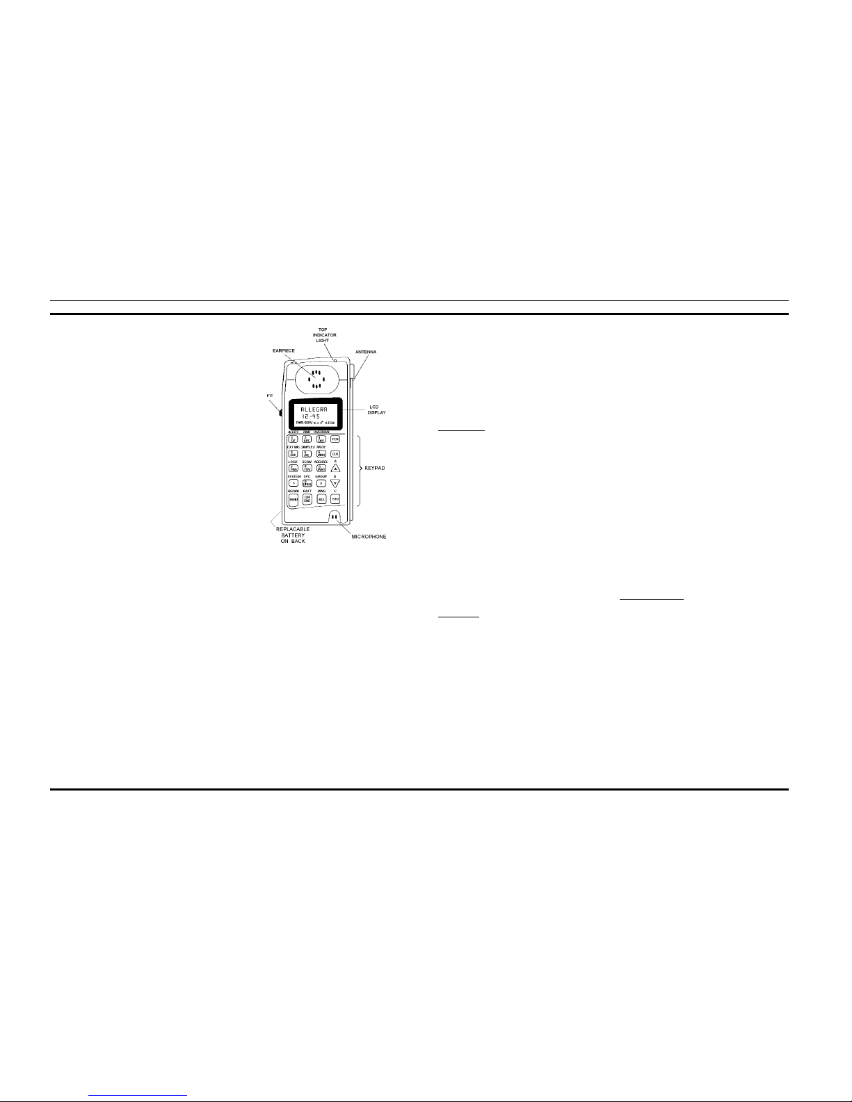
CONTROLS AND INDICAT ORS
The 20 button keypad, and internal speaker and a liquid
crystal display (LCD) are located on the front of the radio.
Viewed from the front, a PTT (push-to-talk) button is located
on the left side adjacent to the display. (Interconnect/Dispatch
models only). The microphone is on the lower left and the
earpiece on the top center. The fold-up antenna is on the top
right side.
The keypad is used for manual number entry, access to a
telephone interconnect system and activation of various
EDACS features. The keypad is divided into a function portion
and a numeric portion as is found on a basic touch-tone telephone.
The display has an eight alphanumeric character line (upper
line) used to show the operational mode of the radio and has a
numeric character line (middle line) used to show talk time.
Eight status indicators, used to indicate various operating conditions, such as; function key pressed, transmitter on, service
available, radio in use, horn alert active, radio locked or transmit
muted, are located below the character lines within the display.
The Allegra Duplex radio also generates a unique set of alert
tones to indicate the operating status of the radio when used in
EDACS applications. The alert tones are defined in the operator’s manual.
Figure 1 identifies the location of all controls and status
indicators.
OPERATION
The radio is powered ON by pressing and holding the
O
button. All status indicators turn on momentarily and after 2
seconds a short beep will be heard and a message “---ON---”
will be displayed on the LCD. A self diagnostic test is performed
when the radio is first turned on if enabled through programming. In the Interconnect Only Model, the display will then
display “CC SCAN“ if looking for the contact channel or
“READY“ when the control channel has been found and a call
request can be placed. To turn the radio
OFF,
press and hold
the
O
button again. After 2 seconds a short beep will be heard
and a message “TURN OFF” will be displayed on the LCD.
When turned off, the radio retains the last user selections (unless
programmed for a particular power up option). Additionally, the
O
key is used to terminate interconnect and individual calls.
Refer to EN/LZT 123 1872 for detailed operating proce-
dures.
CIRCUIT DESCRIPTION
LOGIC BOARD
The logic board, through the use of a microprocessor,
controls the operation of the radio. The keyboard accepts user
inputs and forwards this information on to the microprocessor. The microprocessor executes the user selected functions
and then displays related user information on the LED to
facilitate operation.
Microprocessor
The control center for operations on the logic board is the
Intel 80C51GB microprocessor, D701. The microprocessor
is connected by a parallel bus to a 128K x 8 flash prom (D703)
for operational software, a 32K x 8 RAM (D707) for temporary data storage, and an Ericsson ASIC modem chip (D702).
It controls the Audio Signal Processor (ASP) (D601), a
DTMF generator, the LCD display, and the personality
EEPROMS by way of serial lines. The microprocessor has
five single bit I/O ports for controlling the synthesizer, keypad, and audio functions not provided in the ASP’s registers.
There is an A/D port on the microprocessor which is used to
make battery voltage and RSSI (Receive Signal Strength
Indicator) measurements and also as input lines for the keyboard. The microprocessor’s async serial port is used to
provide a path into the radio for personality programming,
flash programming and test. The async serial port is available
at the UDC connector of the radio at a 5 volt level. These
levels must be converted to RS232 levels by an external
device, such as a TQ3370, before being connected to a computer.
Modem ASIC
The modem ASIC, D702, executes a variety of housekeeping chores in addition to its data function. It also controls
the ALE Latch function of separating the lower address byte
from the microprocessor’s multiplexed data and address
lines. The demultiplexed lower address byte is used by the
ram and flash prom.
The power-up reset pulse from the LM2951 5V (N805)
regulator and level inverter N712/1 pin 3 comes into the
modem on RESIN (33). It is OR’ed with the output of an
internal watchdog timer circuit before being outputted on
RESOUT (43). This line is then inverted by N712-4 before
being used as the system reset line. The watchdog waits about
two seconds before resetting the system.
The system clock is generated from an 11.059 MHz
crystal (B701) by an oscillator circuit in the modem chip. The
buffered output of this oscillator (Clk1) provides the master
clock to the microprocessor and the ASP chip. The modem
chip also divides the 11.059 MHz frequency down to 614 kHz
at CLK2. This line is used to generate the floating voltage
required by the LCD display. It is also used as a clock for the
busy tone notch filter and the clock into the Bertram ASIC on
the RF board. Transistor V701 is used to add another capacitor to the crystal circuit to move its frequency slightly to avoid
micro spurs. V701 is controlled by open collector switch SW3
of the ASP IC.
The timing for the data modem part of the ASIC is also
derived from the chip’s oscillator. The modem consists of a
digital phase locked loop (PLL), receive data detector, an
eight bit shift register for transmit, and a sync word detector.
It will also generate an interrupt to the microprocessor. The
register bit that resets the watchdog is also located in one of
the data modem registers.
Device address decoding is accomplished by a simulated
74HC138 within the modem ASIC. Addresses A15, A14, and
A13 are brought into the ‘C,’ ‘B’, and ‘A’ inputs of the
“HC138” to divide the data space into 8K segments. The
lower two spaces, Q0 and Q1, are AND’ed with gate U710-3
and used to select the lowest 16K of the microprocessor
address space and the upper 16K of the 32K x 8 ram.. (Note
that A14 of the ram is pulled to 5V, forcing the chip to
selection the upper 16K. Q3 selects the data modem registers
of the modem chip. The 32K combined decode of Q4 through
Q7 is not used. The HC138 is enabled on its “G2B” input by
P5.6 of the microprocessor. This allows the microprocessor
to remove the ram and data modem from the address space
during flash prom programming.
Flash Prom Circuitry
The flash prom containing the radio’s operating software
(D703) is an Intel 28F001 128K x 8 byte memory. The block
feature of this device is not used. The VPP flash voltage
connects to both VPP (9) and PD (6). The 128K byte memory
is segmented into 64K banks by connecting P5.7 of the
microprocessor to A16. The micro’s PSEN enable is connected directly to the prom’s output enable for read operations. PSEN is AND’ed with the micro’s P5.6 flash write
enable line to form the prom’s chip select. In normal operation, the device is only selected when PSEN is low. During
flash programming, the prom is always selected.
Flash programming requires the use of software inside the
microprocessor. Normally, the VPP flash voltage is not connected to any source. For flash programming, it is connected
to a +12V supply at the UDC connector. This voltage is
divided down to provide a 5V level to the processor’s EA pin.
This sets the processor into a mode where the lower 16K of
the address space is internal to the microprocessor. This space
contains the software to address the flash prom, read and write
Figure 1. Allegra Controls and Indicators
AE/LZB 119 1645 R1B
3

a packaged protocol from the microprocessor’s serial port,
keep the watchdog occupied, and implement the prom manufacturer’s programming algorithm.
Normally, the radio is flashed through a TQ3370 interface
device. This TQ3370 contains circuitry to convert the battery
output of the radio to 12 volts. The radio should be power
cycled when being flashed so that the microprocessor is reset
with the VPP supply on. This will allow it to begin running
with EA high and to execute code from its internal memory.
Note, there is no solid mechanism for causing a reset when
VPP is applied. However, there is an implied mechanism in
that when one applies VPP , one changes the system’ s memory
map. This will probably crash the operating software. The
modem’s watchdog may then fire and the microprocessor
should come up with its internal program running.
For flashing, the prom is broken down into four 32K
banks. This is so the prom can “appear” to be in the upper
32K of the microprocessor’s data space. A16, controlled from
P5-7 of the microprocessor, handles half of this task just as it
does in normal operation. A15 is AND’ed with the P3.5 of the
microprocessor. In this way , it is poss ibl e to phys ical ly write
prom address 0000H while it appears to be at address 8000H
to the microprocessor. The write line into the flash is also
AND’ed with P5.6, the flash write enable line. This provides
some protection against inadvertent writes into the flash and
also keeps the write line off of the prom during normal
operation. The flash write enable line also removes the ram
and modem registers from the data space by disabling the
address decoder circuitry inside the modem ASIC.
I2C Device Interface
The microprocessor runs several sets of serial devices
through its data I/O lines. One set of lines forms an I
2
C bus.
This is a standard arrangement involving a bi-directional data
line and a microprocessor generated clock line. The data line
is called ‘DATA, K-R3 and is on P1.2 of the microprocessor.
Note it is multiplexed with row three of the keyboard and the
data lines of the synthesizers. The clock line is called IICCLK and is generated by P4.4 of the microprocessor. There
are three 24164 serial EEPROMS (D801-D803), a DTMF
generator D804, and the LCD display (N806) on the I
2
C
lines.
The serial EEPROMS are 2K x 8 devices. There is an
address field in the I
2
C data stream. The 24164 device is
easily paralleled with other I
2
C devices by setting its three
hard-wired upper address lines. Their flexibility is also useful
for working around the less adaptable DTMF generator and
LCD display. The EEPROMS are used to store personality
data.
The DTMF generator runs off of a color burst crystal
(B801). It can generate any of the sixteen tone combinations
under control of the microprocessor. It also has power saving
and spur reducing functions that cut off the oscillator. DTMF
tone out of the IC goes into the external microphone input of
the ASP ASIC.
The LCD display is another I
2
C device. It can be considered as a six pin connector on the board. One line is ground
and two are the I
2
C clock and data lines. The display also
requires a 5V supply and a high value resistor to ground for
its oscillator circuit. The VLCD line provides a variable
voltage for contrast. It is generated by rectifying the 614 kHz
clock to develop a floating voltage. It is then run through a
simple transistor regulator with a thermistor in the reference
setting voltage divider. The voltage at the pin varies from -0.5
to +0.5 volts, referenced to ground depending on temperature.
Low temperatures will generate negative voltages.
Bertram IC Interface
Another set of serial control lines is used to talk to the
Bertram chip on the RF board. Bertram requires four lines,
called CLOCK, LATCH, DFO, and DTO. The CLOCK line
is generated from the modem’s 614.4 kHz line. It is gated on
and off under control of ‘CLK-SEL, bit P4.6 of the microprocessor. The clock line is also capable of being read by the
SEP-CLK(P4.0) line of the microprocessor. The LATCH line
is generated by bit BERT-LE (P4.5) of the microprocessor.
Data from Bertram comes in on the SEP-DAT (P4.1) line of
the microprocessor. It is also AND’ed with the data to Bertram by an AND gate. This is because Bertram expects a
closed loop circular serial bus. Data to Bertram comes from
the DI-EW, K-R2 on P1.1 of the microprocessor. Note, it is
multiplexed with row two of the keyboard. The complex
timing of these lines is accomplished under software control
by the microprocessor.
Bertram is used to provide divider information to the
synthesizers and return lock status. The chip also generates a
TTL level CAS signal when the received signal strength is
above a threshold value. This is called RXCD at the J101 RF
board to logic board connector and RSSI or microprocessor
A/D bit ACH5 on the logic board.
Synthesizer Interface
Four microprocessor bit ports are used to load and control
the synthesizers on the RF board. They form a serial bus
consisting of a data, clock and latch line. They are DATA,
K-R3, CLK, K-R1, LTX, and LRX. The synthesizer data line
is DAT A, K-R3 from microprocessor port P1.2. It goes to both
synthesizers. The synthesizer clock line, CLK, K-R1 comes
from microprocessor port P1.0 and is also used for both
synthesizers. The latch lines are separate for each synthesizer.
The latch line for the receive side is LRX (P5.4). The latch
line for the transmit side is LTX (P5.3). The timing of these
signals is under control of the microprocessor’s software.
ASP Interface
The microprocessor receives and sends information to the
ASP ASIC over a three wire serial bus. The information consists
of a data, clock, and enable line. DATA, K-R3 (P1.2) is used
once more as the data line. CLK, K-R1 (P1.0) is used as the
clock and is also multiplexed with the synthesizer and keyboard.
The enable line is unique to the ASP. It comes from P4.7
(ASP-EN) on the microprocessor. The master clock for the ASP
is the buffered 11.059 MHz (ASP-CKIO) clock out of the
modem ASIC. The ASP is discussed in more detail in the audio
section.
Keyboard Interface
The Allegra radio uses a software scanned keyboard consisting of 20 keys in a five row by four column matrix. It is not an
actual keyboard. Instead, it consists of interweaved gold plated
runs of signal and ground on the logic board that get shorted
together by conductive pads on the front panel’s rubber keypad.
The keyboard is scanned by pulling down the row lines one at
a time and reading the column inputs. The rows are output on
the lower five bits of port 1 of the microprocessor. The columns
are read as digital inputs on the lower four bits of the microprocessor’s A/D port.
The first three row lines are multiplexed with other functions. Each row control pin (except for row 5) pulls the keyboard
row low through the associated diode. This prevents a user who
is using the keyboard from corrupting the multiplexed functions. There are also two keys that are direct inputs to the
microprocessor. The first is the PTT switch. It is connected to
microprocessor port P3.2. The second is ON/END. It is connected to microprocessor A/D port ACH4. This switch is also
connected to the radio’s power switch circuitry. The PTT and
ON/END switch also exit the radio through the UDC connector.
The radio’s LCD display and keypad are backlit by 12
LED’s. The display consists of six paralleled lines of two LED’s
in series. The bottom of these lines is pulled to ground by two
transistors to distribute the power dissipation. These transistors
are controlled by microprocessor port P5.5 through a PNP buffer
transistor.
Battery Power Control Circuits
Power is supplied by the battery and applied to the radio
through power FET (field effect transistor) V801. The FET is
controlled by P-HOLD (ASP switch SW4) or from the keyboard’s ON/END switch. When the radio is “off”, no power is
applied to the system, thus keeping P-HOLD open and V806
off. When ON/END is not pressed, it is open. This keeps PNP
transistor V803 off which in turn keeps NPN transistor V805
off. Transistor V805 actually controls the power FET’s gate.
Pressing the ON/END key brings the line low turning on V803.
V803 then turns on V805 which then turns on power FET V801.
The system will power up. This includes turning on the 5V
regulator and generating a reset pulse for the system.
When the radio is “on”, pressing the ON/END key long
enough will tell the radio to turn itself off. It does this by clearing
P-Hold, which then turns off V806. When the ON/END key is
released, V803 turns off which turns off V805. V805 will then
turn off power FET V804, cutting off power to the radio.
Three other circuits relate to the battery. First, the battery
voltage is divided by 2 and applied to the BATT-TEST input on
the microprocessor’s A/D (ACH7). Second, microprocessor
port BATT-LED (P3.4) is used to control the LED at the top of
the radio. It is used when the microprocessor detects low battery
voltage. Third, microprocessor port P5.2 (SWDIS) is used to
control the SWDC 5V at the UDC connector through a PNP
transistor.
Receive Audio
The 450 kHz IF is brought in from the RF board and applied
to the logic board. It is then fed into a phase lock loop discriminator (N603). The difference in frequency between the incoming signal and an internal VCO produces an error voltage that
corresponds to the transmitter’s modulation. The VCO is set to
900 kHz by R603 and C605. There is an internal divide by two
circuit within the IC. The audio output is then passed through
an emitter follower (V601) to the ASP ASIC at pin 50 of the
DISC for squelch and the A1-IN (pin 44) input for the data and
receive audio circuits.
The ASP chip includes two op amp bias supplies: One for
receive functions and one for transmit functions. The inputs for
the supplies originate internally from the chip for bypass capacitors. The input for the Rx bias voltage is pin 39 and the output
is pin 40. For the Tx bias, the input is on pin 64 and the output
is on pin 63. There is also a 1 uF bypass capacitor on the Rx
supply output and a 2.2 uF on the Tx output. The 3V bias
generator of the ASP is not used.
The ASP chip controls the squelch function. Discriminator
audio is received on DISC pin 50 as DISC. It is passed through
a high pass filter to remove voice frequency components and
The microprocessor is capable of reading the ON/END key
directly. It will heavily debounce the key to prevent accidental key presses. Then it will set P-HOLD which will turn on
V806, keeping V805 turned on. The radio will then remain
“on” after the ON/END key is released.
NOTE
AE/LZB 119 1645 R1B
4

then rectified. This voltage is compared with a voltage supplied
under software control, D/A. on the ASP’s. The output of this
comparator is passed to the microprocessor on the ASP CAS
(ACH.6) A/D input line. It is then used in conjunction with the
tracking data to determine if a signal is present. The response
time of the circuit is controlled by external capacitor C640 in
fast squelch mode with C641 being paralleled by ASP switch
SW2 (Pin 16) for the slow squelch function. An external resistor
network including thermistor R642 is used to track out temperature variations. The resistor network interfaces with pins 53-55
of the ASP’s “A” op amp. Squelch hysteresis is assumed to be
a software function.
Demodulated audio also enters the ASP chip RAFI (Pin 44).
It passes through a gain stage and then through a 300 to 3000
Hz bandpass filter before exiting the ASP as HP10 on Pin 45.
Software switches provide for bypassing the bandpass filter.
This is desirable when looking for high speed (9600 baud) data.
In this case, the output HP10, is applied to limiter comparator
NRI (Pin 31) against a 1 uF averaging capacitor at pin 32.
Something wrong in here. ASP switch SW5 (Pin 13) is used to
block the output of the busy tone filter when looking for high
speed data. The output of this comparator is called LOSC (Pin
21). It is buffered by transistor buffer V606 and applied to the
data input of the modem ASIC and the ASP-LDSC (P4.2) input
of the microprocessor.
The notched audio returns to the ASP on pin 28, VGAF. It
then goes into a switch array. This array decides which device
to connect to the speaker. The choices are the unnotched output
of the bandpass filter, the audio from the notch filter, an ASP
generated alert tone, or the output of the DTMF generator as a
side tone. Two external resistors allow adjustment of the alert
tone level. The DTMF input is on pin 29, DTMF.
The de-emphasis network is after the switch. It can also be
switched in and out. The volume control is after the de-emphasis
network. It allows 32 levels of volume under software control.
The digital volume control allows for separate levels for normal
operation and operation in a vehicular charger. The audio passes
through one more mute switch before leaving the ASP on pin
27, RXAF. From here, the audio goes to the expander portion
of a NE578D compander IC, D605. This IC attempts track out
large swings in the volume level to provide a constant level into
op amp N604, which is used as a driver for the earpiece audio.
The compandor function can be defeated by ASP switch SW0
(pin 18). Earpiece audio also goes out the UDC connector as
EXT-SPKR.
The audio input at RAFI (pin 44) can also be connected to
a 210 Hz low pass filter. This strips voice information off to
leave Channel Guard or low speed data information. This information exits the ASP on pin 37, CGO, and passed through
limiter comparator C3 with a 10 uF averaging capacitor, C660.
The data input is on pin 35. The averaging input is on pin 34.
The output of the comparator, LCGO (pin 22) is applied to
microprocessor pin ASP-LCG (P4.3). The low speed data decode or Channel Guard detection is accomplished in software.
The logic board contains a buzzer, H803, which is used to
provide an audible alerting signal. This is accomplished under
software control by toggling microprocessor port BUZZER
(P1.7) on and off at the desired frequency. The port pin, D70129, drives transistor V802 which, in turn, switches the 5v supply
on and off through a 10 ohm resistor.
Transmit Audio
Audio from the internal mic is received by the ASP ASIC on
pin 74, IMIC. Audio from the UDC connector is received by the
ASP ASIC on pin 75, TTON. Both mic inputs provide a bias
voltage from the ASP generated TX BIAS supply. The mic
inputs are then fed to a switch. A third input into this switch is
the DTMF encoder chip on the EMIC (73) pin. (There is a 20
dB pad between the DTMF IC and the ASP input.) After the
switch, the audio passes through a software selectable gain
stage. It then passes through the pre-emphasis filter and then a
300 Hz high pass circuit to keep voice from conflicting with
Channel Guard or low speed data. From there, the audio leaves
the ASP on pin 70, TONE and applied to the compressor side of
the NE578D compandor, D605. The compressor provides an
AGC function to hold the mic audio more constant. From the
compressor, the audio is returned to the ASP on pin 57, TIN. It
passes through a limiter circuit and summed with the data and
tone components of the Tx modulation at a common summation
junction.
High speed data from the modem ASIC is received by the
ASP on D601-80 as IDAT. It passes through a data filter before
being combined with the Tx audio at the common summing
junction. It is possible to bypass the data filter.
Channel Guard and low speed data are generated at digital
levels by the microprocessor on walsh bit outputs WB1 (P5.0)
and WB2 (P5.1). The walsh bits are combined in a resistor
network to act as a two bit D/A. For tone generation, a sine wave
is approximated in six steps to create a more easily filtered
signal. The combined walsh bits enter the ASP at pin 38, TOIN,
for Channel Guard and low speed data.
The DTIN input to the ASP, D601, connects directly to the
common summing junction through a switch. Its audio frequency tones are sufficiently filtered by the post limiter filter i n
the ASIC. The low frequency TIN is passed through the 210 Hz
low pass filter to filter out the waveform. This is required since
higher level harmonics tend to significantly degrade hum and
noise. Note, this is the same filter that is used on the receive
side. The filtered signal exits the ASP on pin 37, CGO. It then
goes to ASP D601-58, CGIN, and into C3, limiter comparator.
CGIN is connected directly to the common summing junction
by a switch.
A 3000 Hz low pass post limiter filter follows the common
summing junction. (This filter can be bypassed when sending
high speed data.) Following the filter is a 32 position deviation control. The output of this attenuator is passed through a
switch before exiting the ASP on pin 60, TXAU. It then passes
through a resistor network before going to the modulation
circuits on the RF board.
RF BOARD
Refer to schematic diagram 188D6251. Each sheet of the
drawing contains a major board function. These functions and
locations are listed below:
• Sheet 1 RF board control and block diagram.
• Sheet 2 Transmitter
• Sheet 3 Transmit synthesizer
• Sheet 4 Receiver synthesizer
• Sheet 5 Receiver
Power Distribution
DC power is supplied to the radio by a NiCd battery At
full charge the battery delivers 7.2 volts to the radio. If the
output voltage falls to is less than 5.3 volts, the Audio/logic
board turns the radio off.
DC voltage from the GEL Cell battery pack is applied to
the RF board through J103.1, 2 and fuse F101. Test points
TP168 and TP108 allow you to monitor the battery voltage
on either side of the fuse. Unregulated, unswitched voltage
only is applied to the transmitter power amplifiers U200,
Q200, and to the Audio/logic board through J101.8. Battery
voltage is connected to accessory connector X201 and to 5
volt regulator and switching circuitry consisting of V804,
MBT3904 and MBT3906. This switching circuitry generates
SWDC (switched 5 Vdc) which is returned to the RF board
on J101.1 as SWDC. SWDC is applied to Power Regulator
U161, Bertram RF Controller (U101-3) as VBAT and pin 1
as STARTUP, and to DC control Transistor Q131. Control
transistor Q131 supplies SWDC to 5 volt regulator D100. The
output of the regulator is distributed as VREG to the receiver,
TCXO, Bertram U101-5 (TP131) and pins 16 and 37 through
respective voltage dividers, and to MOSFETS Q511 and
Q531.
VRX is originated by U161 and applied to receiver synthesizer U400, RXVCO U410 and driver U430 and to pass
transistors Q161 and Q162. The pass transistors are controlled by the Bertram RF Controller and supply voltages VTX1
(TP162) and VTX2 (TP164) to the transmitter circuitry:
U200, U300, TXVCO U310, and MOSFET driver Q330.
C116 provides low frequency filtering while capacitors
C101 through C115 decouple any noise transients that may
be present on the control lines to the Bertram Radio Interface
Controller. TP109 allows the technician to monitor the POWDET line.
Transmitter:
The transmitter contains preamp Q200 and power amp
U200, with a broadband 815 MHz filter feeding the antenna
connection. The transmitter PA delivers 0.75 watts (0.4 watts
on low power) to the antenna.
Bertram Radio Interface Controller U101 receives instructions form the Audio/Logic board via serial data link,
J101.11, identified as “DFO”. Information is returned to the
Audio/Logic board through J101 -13 and is identified as
“DTO”. Both DFO and DTO are clocked by J101.12 (C1008).
Transmit on-off switching is controlled by Bertram Radio
Interface Controller using two switching circuits. Bertram
output, Dout4 (U101-20), controls voltage switching transistor Q161 (TP162). Q161 switches power on/off to transmitter
PA U200, transmit synthesizer U300, RF power sense D240,
RF amplifier Q200, and buffer Q330. TXON control from the
Bertram (DOUT1, U101-41) controls transmit on-off switch
Q201. Q201 switches amplifier Q200 on and off as required
by the current status of the radio.
Transmitter output power is regulated to its high or low
tracking data setting (see Audio/logic board) by sensing
(transformer W202/W203) and detecting (D240, C241) final
power (Bert op amp #1 pin 38, 39, and 40) relative to the DAC
setting (Bert output pin 35) obtained by Bertram from the
Audio/Logic board.
Tx-Synthesizer:
The channel frequency is set by loading transmit synthesizer chip U320 from the Audio/Logic board via J101.5 and
J101.6, “Syntcl” and “Syntdata”. The synthesizer chip sets
the channel center frequency through its fN pin U320-10 and
monitors/locks the frequency by “listening” to the VCO output via C312. Audio signals from the audio/logic (J101.7
“Mod”) varies the VCO (U310) frequency according to the
audio amplitude set on the Audio/Logic board. Transmit
synthesizer chip voltage is switched on-off in the same fashion as the transmitter power out, by Bertram ‘Dout3’, via
voltage switching transistor Q162. The switched voltage is
designated as VTX2. Q330 is used to buffer the VCO out, and
feeds the transmitter pre-amp. Power to buffer Q330 is
brought in from VTX1 under control of Bertram ‘Dout4’.
AE/LZB 119 1645 R1B
5
Rx-Synthesizer:
The receive channel frequency is set in the same manner
as the transmit channel frequency, except its components, the
Synthesizer chip (U420), the buffer (U430), and the VCO
(U410), get power from VRX. VRX is controlled from the
Audio/Logic board (J101.1 “SWDC”) through power control
chip U161.
Receiver
The antenna input feeds broadband filter FL501 which, in
turn, feeds input buffer/amp Q511. “The output of buffer/amp
Q511 is then filtered by FL521. The 1st IF frequency is
provided by mixer Q531. Q531 combines the Rx Synthesizer
output with the antenna signals to generate the 1st. IF frequency. The output of the 1st mixer is coupled to the input of
77.25 MHz SAW filter FL541 through a parallel resonant tank
consisting of L531, C538, and C539. The IF filter FL541
passes only the tuned channel frequency at 77.25 MHz. This
first IF is down converted to 450 kHz (into Bert) 2nd mixer
U501. The output of the mixer U501-14 is routed to pin 15 of
the Bertram Radio Controller and to the Audio/Logic board
through J101.15 (TP115).
SERVICE SECTION
The Service Section contains information designed to
assist you in the proper care and maintenance of your radio
and to insure optimum performance. Alignment of the radio
consists of performing the tracking procedures included in
this section. Various dis play indicators and tones provide the
current operating status of the radio.
CARE OF EQUIPMENT
1. Keep the exterior of the radio clean. Use a soft damp
cloth.
2. To ensure efficient power transfer from the battery
to the radio, wipe the contacts of the battery and
radio to remove dirt or grease; Use a soft dry cloth.
3. When the accessories connector is not in use, cover
the connector with the protective dust cap to prevent
he build up of dust or water particles.
SERVICE & TROUBLESHOOTING
Troubleshooting the radio in the field consists of board
substitution using boards taken from a radio that has been
proven to operate in accordance with manufacturers specifications. Service and tracking procedures are provided for
reference only. Successful completion of these procedures
assure the radio will perform in accordance with the manufacturers specifications.
LOGIC BOARD TEST PROCEDURE
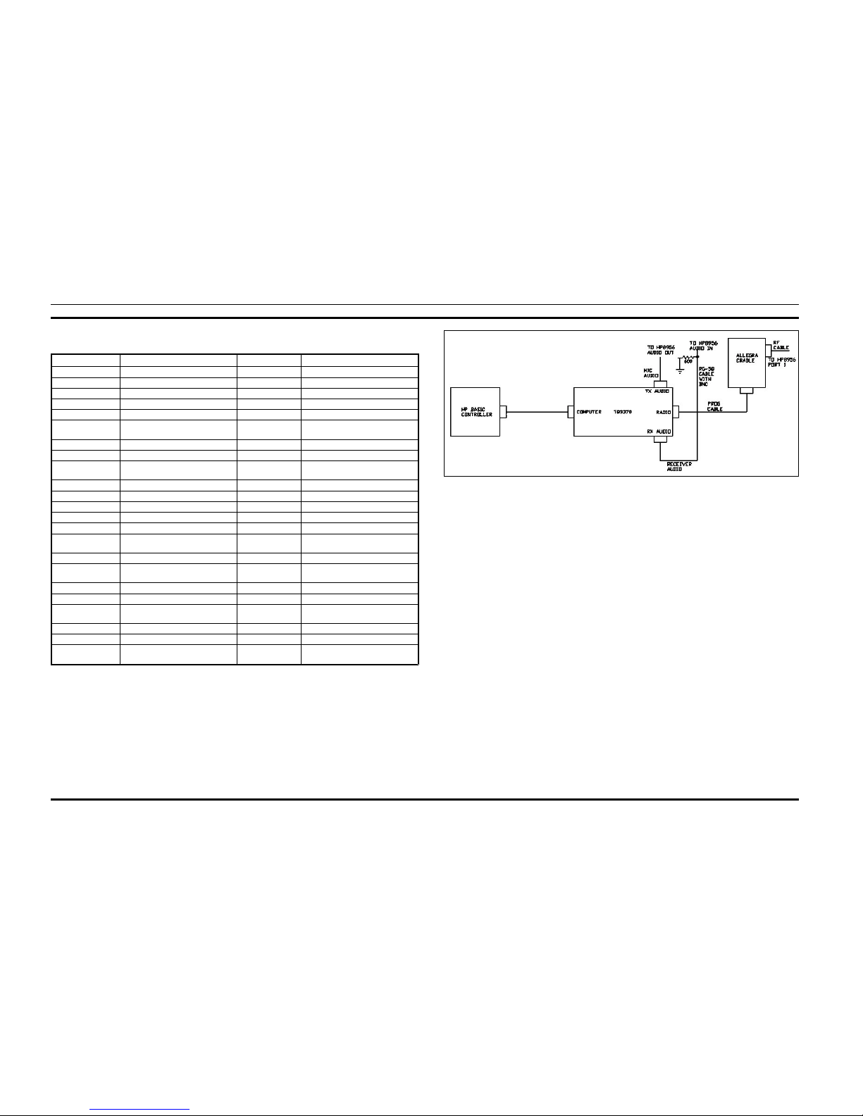
Test Fixtures:
The logic board is tested using a TQ3370 interface box
and interface cable to connect the logic board to a DOS based
computer. The cable between the TQ3370 box and the logic
board is shown in Table 1. The cable connects to X201 of the
logic board. The logic board is powered from a 7.0 volt supply
through the TQ3370 interface box.Figure 2 shows a test setup
diagram to test the logic board.
Reference Drawings
344A4736 .............................Flash Programming Specification
350A1225 ...........................................Personality Specification
CXC 112 874.................... Dispatch and Interconnect Software
CXC 112 873.................................Interconnect Only Software
Test mode software allows access to most radio functions.
It consists of binary commands with appropriate parameters.
The logic board responds to a command by executing the
requested action, returning any appropriate data: a completion
code of 01h if “successful” and 02h if “failed”, and a ““ to
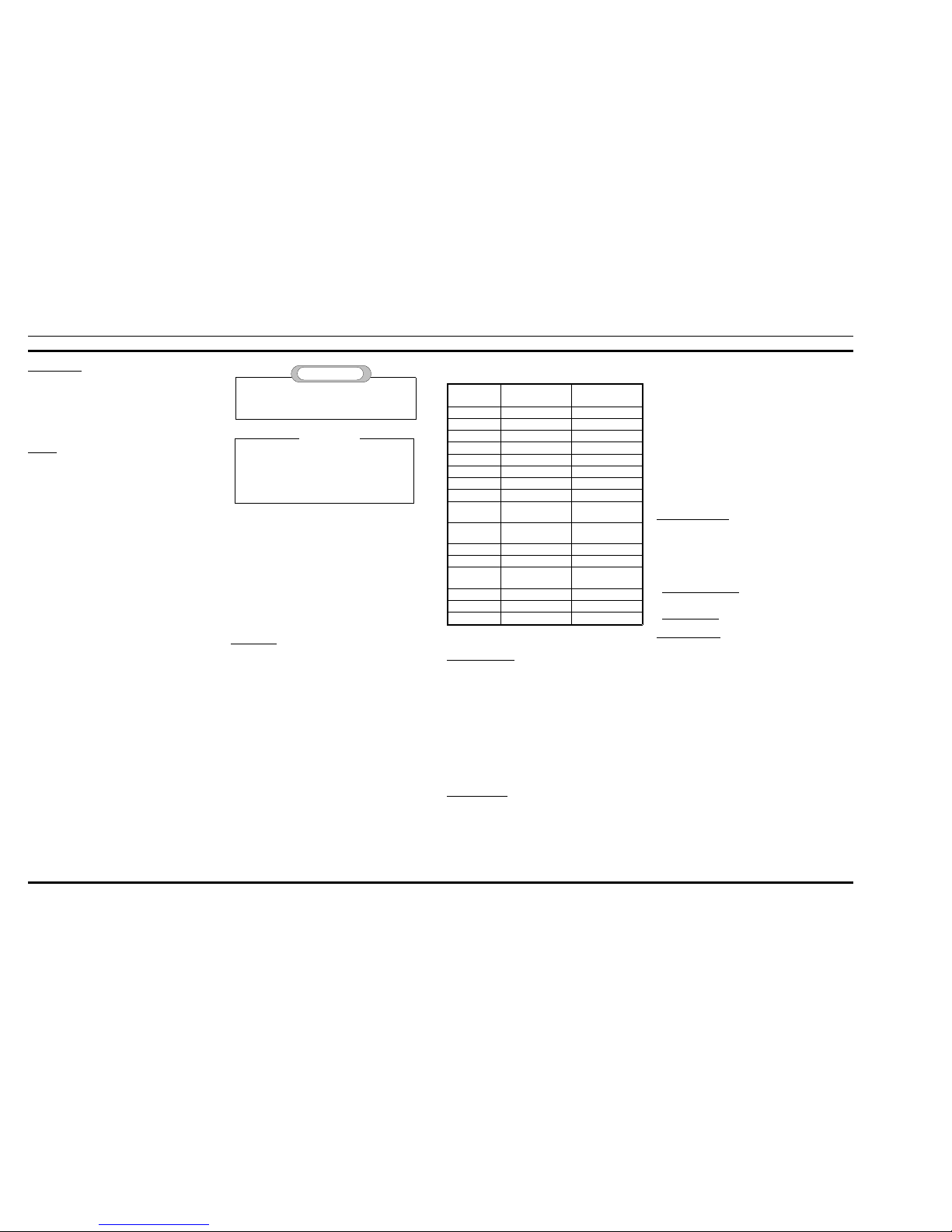
indicate it is ready for the next command. Table 2 is a list of test
functions.
Visual Inspection:
Carefully inspect the solder connections to the pins on X101
(Connector to RF board), D6 01 (ASP Chip), D703 (Flash
Prom), and D707 (Ram). These are fine pitched parts. The use
of a microscope is recommended.
POWER-UP:
1. Verify DTR on the computer is in its positive voltage
state.
2. Verify the power supply is off.
3. Connect the Logic Board under test to the TQ3370
Interface Box.
4. Apply 7.5 volts to the TQ3370 Interface Box. Note,
there are two diode drops in the TQ3370 box between
the power supply and the logic board. The TQ3370 box
will use about 50 Ma of current. Current from the
supply must be under 150 Ma
Flash Program Code:
Flash the current version Allegra operating software into the
logic board with the current ‘FLASH.EXE program. Successfully flashing the radio verifies that most of the logic circuitry
is operating properly. The flash programming protocol for the
Allegra Portable is:
Interconnect w/Dispatch: CXC 112 874 (Identified by the
presence of a PTT switch on the side.)
Interconnect Only: CXC 112 873 (No PTT switch)
Initiate Test Mode:
1. Power cycle the radio.
2. Put a “break” condition on the serial port for about one
second. The logic board will respond with an ASCII
“>“ (3eh).
3. Send an ASCII “GE” (47h 45h) to the logic board. This
puts it in programming mode. The logic board will
show the software revision on the display and will
respond with six bytes (plus a “>“) per the personality
programming specification.
4. Send an ASCII “GF” (47h 46h) to the logic board. This
places the radio in test mode. The logic board will
respond with an ASCII “>“ (3eh).
Do not carry the radio by the antenna. Do not use
chemical cleaners, spray or petroleum based p roducts.
They may damage the radio housi ng .
CAUTION
Field repair is limited to removal and replacement of
the RF or Logic Board and case assembly parts such as
PTT switch, covers, antenna, keypad, etc. If more intense servicing is required, return the radio to your local
Ericsson Dealer for factory repairs.
NOTE
Radio Pin
Number
TQ3370 Pin Number Description
1 16 External Mic
2 Service - 1
3 Unmute
4 1, 2, 3, 4, 13 Ground
5 14 External Speaker
6 Service - 2
7 9, 25 Service - 3
8
9 12 Rxd (TQ3370 to
Logic Board)
10 11 Txd (Logic Board
to TQ3370)
11 17 ON/END
12 SW 5V
13 6, 8, 18, 20 Vbatt (Power To
Logic Board)
14 15 Ptt Switch
15 5 12V Flash Voltage
16 1, 2, 3, 4, 13 Ground
Table 1. Logic Board to TQ3370 Interface Cable
AE/LZB 119 1645 R1B
6
Test Mode Code Function Test Mode Code Function
(01) Select Channel (19) Enable/Disable The Busy Tone Filter
(02) Select Frequency (1A) Enable/Disable The Busy Tone Filter
(03) T oggle Transmitter On/Off (1B) Initialize The Asp To A Known State
(04) T oggle Receive Audio On/Off (1C) Generate Standard/Alternate Busy Tone
(06) Toggle High Speed Data On/Off (1E) Manipulate The Synth Bandwidth
(07) Toggle Low Speed Data On/Off (1F) Manipulate MDR/MDX Specific
Parameters
(08) Report Receiver Carrier Sense (20) Read Tracking Data
(09) Generate Alert T one (21) Write Tracking Data
(0A) Write External Ram (22) Set D/A And Read Output Bit Of
Squelch
(0B) Read External Ram (23) Set Tx Deviation
(0C) Report Software Checksum (24) Set Volume
(0D) Conduct Modem Loopback Test (25) Set Tx Output Power Value
(0E) Report K ey Press/Releases (26) Xram Test
(0F) Write 1 Audio ASIC Registers (27) Set Bertram Chip On/Off
(10) Write All Audio ASIC Registers (28) Write 1 Audio ASIC Registers With Bit
Mask
(11) Report Audio ASIC Registers (29) Test Of Rx And Tx Synthesizer Lock
(12) Do A Dacs Control Channel
Transmission
(2A) Test Of Personality EEPROM
(13) Return To Programming Mode (2B) Report Battery Sense A/D Value
(14) Generate DTMF Tone (2C) Receive Audio Motorboating Test
(15) Transmit Digital Data (2D) Toggle All LCD Segments And LED’s
On And Off
(16) Receive Digital Data (2E) Report Current Keypad Condition
(17) Detect A Tone (2F) Toggle Buzzer On/Off
(18) Generate/Decode Digital Channel
Guard
(30) Bertram Reference Voltage Trimming
Table 2. Test Mode Functions
Figure 2. Logic Board Test Setup Diagram
AE/LZB 119 1645 R1B
7
MEMORY TESTS:
1. Run the Xram test by sending a 26h command to the
logic board. If successful, the logic board will respond
with a 01 3e.
2. Program default tracking data with the 21h test command. The format is:
21h
addr
data
where the tracking data address is listed below in Table
3. The logic board will respond with a 01 3e if the
command was successful.
3. Verify the tracking data with the 20h test command.
The format is:
20h
addr
where addr is the same as the programming tracking
data test command 21h. The logic board will respond
with the requested tracking data value and a 01 3e.
4. Send a 13h test mode command to get back into
programming mode.
5. Program a default personality with the current PC
Programming program.
6. Send an ASCII “GF” (47h 46h) command to get the
radio back into the test mode.
AUDIO TESTS:
1. Test DTMF by sending the following sequence to the
logic board:
1b Initialize asp
04 01 Turn on the speaker
24 3f Set max volume
14 0e Generate 1477 Hz
2. Measure at least 1 Vrms at X201 Pin 1.
3. Measure 1477 Hz +/- 5 Hz at X201 Pin 1.
4. Measure distortion at X201 Pin 1. It should be less than
5%.
5. Disable DTMF generation
6. Test the alert tone by sending the following sequence
to the logic board:
09 01 Generate tone
7. Measure at least 1 Vrms at X201 Pin 1.
8. Measure less than 5% distortion at X201 Pin 1.
09 00 Disable alert tone generation
9. Test the buzzer by sending the following sequence to
the logic board:
2f 01 Enable buzzer
10. Verify the buzzer is sounding
2f 00 Disable buzzer
DISPLAY TEST:
1. Send a 2d 01 command to the logic board. All segments
in the display must turn on. All LED’s must turn on.
2. Send a 2d 00 command to the logic board. All segments
in the display must turn off. All LED’s must turn off.
KEYBOARD TEST:
The logic board takes one sample of the keypad and
reports a code out the serial port when it receives a 2eh
command. Test for each of the logic board’s keys. Note the
ON/END key can not be tested. It can not be read because
it is being held low by a ground in the TQ3370 box on X201
Pin 11. The return codes are listed below in Table 4.
ELECTROSTATIC DEVICES
DISASSEMBLY AND REASSEMBLY
The following procedures are intended to facilitate the disassembly and re-assembly of the radio. The complete set of
procedures are given since the antenna assembly requires complete disassembly. Refer to assembly diagram ROA 117 2224.
Tool Recommended: Disassembly Tool 19B802630,
1/4” Hex driver
Disassembly
1. Remove the antenna connector screw on the back of the
case, next to the antenna. NOTE: Some versions have a
rubber cover over this coaxial connector.
2. Remove the battery. Refer to procedures ”Inserting and
Removing the Battery”.
3. After removing the battery, remove the two screws (now
exposed) from the case assembly.
4. Using the antenna tool, (or carefully bend the case sides
outward) to release the plastic tabs, two in each side.
5. Tilt the case backwards and upward toward the antenna
end. Remove the coaxial collar.
6. Lift off the RF board assembly with the shield box.
7. Remove the antenna assembly.
8. Lift out the audio logic board.
9. Lift off the PTT button.
Reassembly
1. Check the placement of the buzzer and microphone. Be
sure the buzzer gasket is properly seated over the edge of
the board.
2. Be sure the LCD is placed against alignment edges on
the lightguide.
3. Guide the audio/logic board into the case. If the buzzer
and/or microphone keep the board from seating, realign
and retry.
4. Place the RF board onto the frame.
5. Place the antenna assembly into the frame making sure
that the coaxial connector protrudes through the RF
board.
6. Place the coaxial collar onto the RF board assembly.
7. Carefully seat the RF assembly onto the audio/logic
CMOS Integrated Circuit devices used in
this equipment can be destroyed by static
discharges. Before soldering one of these
devices, the service per son shou ld disc har ge
himself by touching the case of a benc h t est
instrument that is equipped with a 3-prong power cord
connected to an outlet with a known good earth gr ound.
When soldering or desoldering a CMOS device, the soldering iron being used should also have a 3-prong p ower
cord connected to an outlet with a known good earth
ground. A battery operated soldering iron may be used in
place of a standard soldering iron.
CAUTION
00 High Power - Low Split 04 High Power - Mid Split 08 High Power -High Split
01 Low Power - Low Split 05 Low Power - Mid Split 09 Low Power - High Split
02 Voice Deviation - Low Split 06 Voice Deviation - Mid Split 0a Voice Deviation - High Split
03 Data Deviation - Low Split 07 Data Deviation - Mid Split 0b Data Deviation - High Split
0c Battery Correction Factor
18 Squelch Setting
Table 3.Tracking Data Address For Tes t Mod e Co mmands 20 & 21
KEY CODE KEY CODE KEY CODE KEY CODE
1 01 80 3E 2 01 40 3E 3 01 20 3E FCN 01 10 3E
4 02 80 3E 5 02 40 3E 6 02 20 3E CLR 02 10 3E
7 04 80 3E 8 04 40 3E 9 04 20 3E UP 04 10 3E
* 08 80 3E 0 08 40 3E # 08 20 3E DOWN 08 10 3E
SEND 10 80 3E ON/END ----------- RCL 10 20 3E STORE 10 10 3E
PTT 10 01 3E NO KEY 10 00 3E
Table 4. Keyboard Return Codes
h
AE/LZB 119 1645 R1B
8
 Loading...