

Page 1

Service of the Telephone EN/LZB 119 2506 R1A
Chapter 5
Service of the Telephone
Ericsson Cellular Phone AF738
AF778
i
Page 2

EN/LZB 119 2506 R1A Service of the Telephone
SUBJECT .................................................................................... PAGE
Introduction.........................................................................................................5-1
Repair Flow .........................................................................................................5-2
Figure 5-1. Repair Flow.....................................................................................5-2
Table 5-1. Repair Actions..................................................................................5-3
AF738 Internal Components...............................................................................5-4
Figure 5-2. AF738 Internal Components............................................................5-5
AF778 Internal Components...............................................................................5-6
Figure 5-3. AF778 Internal Components............................................................5-7
Common Telephone Failures ..............................................................................5-8
Table 5-2. Common Failures..............................................................................5-8
Required Tools ..................................................................................................5-11
AF738 Disassembly............................................................................................ 5-12
Main Disassembly ........................................................................................... 5-12
AF778 Disassembly............................................................................................ 5-13
Main Disassembly ........................................................................................... 5-13
Replacing The LCD/Lightguide Assembly ....................................................... 5-15
Figure 5-4. Removing Lightguide Assembly.................................................... 5-15
Figure 5-5. Board Revision Level ....................................................................5-16
Figure 5-6. Replacing Lightguide Assembly ....................................................5-17
Replacing the Vibrator Motor Assembly (AF778 Only) ...................................5-18
Replacing the Vibrator Motor..........................................................................5-18
Figure 5-7. Vibrator Motor Assembly..............................................................5-19
Replacing the Vibrator Connector....................................................................5-19
Replacing the Vibrator Wires........................................................................... 5-20
Replacing the Keypad......................................................................................5-20
Replacing the System Connector......................................................................5-20
Reassembly ........................................................................................................ 5-21
AF738 Reassembly ..........................................................................................5-21
AF778 Reassembly ..........................................................................................5-22
Torquing Instructions.......................................................................................5-24
Figure 5-8. Torquing Sequence........................................................................5-24
Return to Service Checkout ..............................................................................5-24
ii
Page 3

Service of the Telephone EN/LZB 119 2506 R1A
iii
Page 4

Page 5

Service of the Telephone EN/LZB 119 2506 R1A
Introduction
This chapter contains Level 3 repair procedures for the Ericsson AF738 and AF778
cellular telephones. Please follow the checkout procedures before returning the unit
to Ericsson Product Repair Center.
5-1
Page 6
EN/LZB 119 2506 R1A Service of the Telephone
Repair Flow
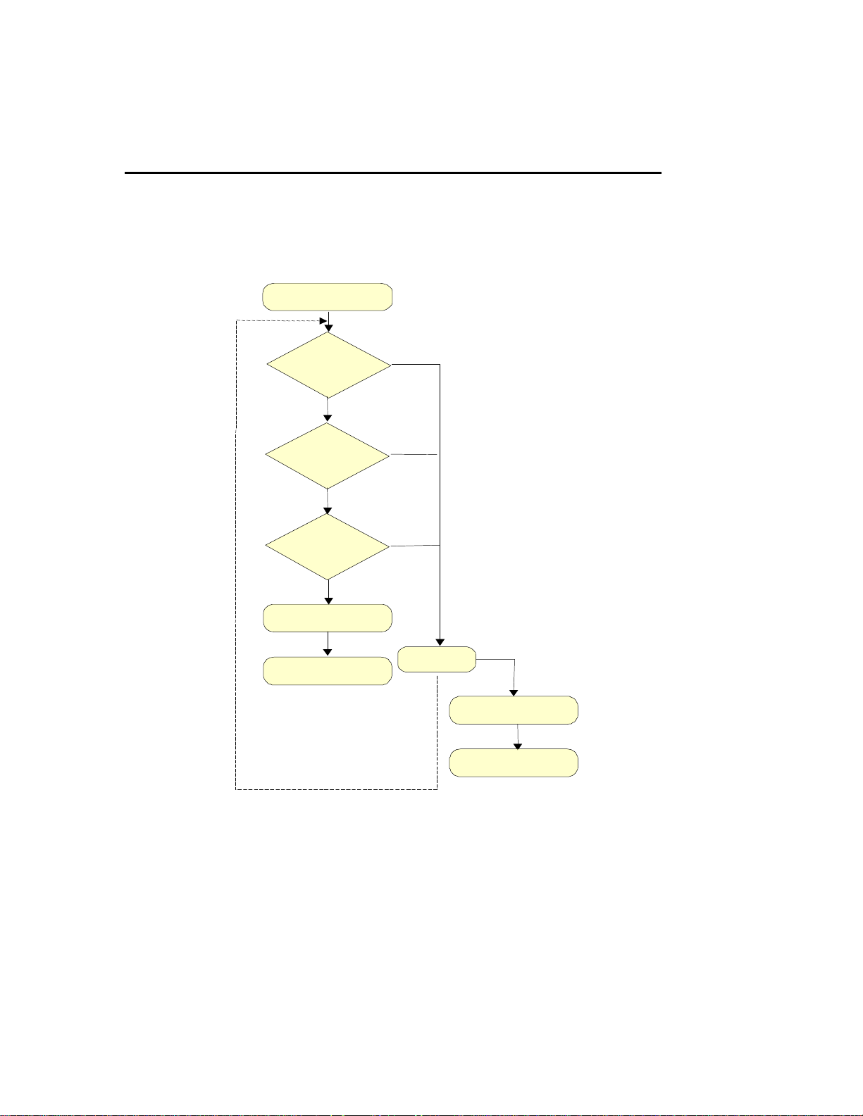
See Figure 5-1 and Table 5-1 for Level 3 repair flow and actions.
From Customer
Visual
Inspection
OK
Go/No Go
Test
OK
On-The-Air Call
OK
Warranty Seal
To Customer
Fail
Fail
Fail
Repair
Fail
OK
Warranty Seal
To higher level
of service
5-2
Figure 5-1. Repair Flow
Page 7
Service of the Telephone EN/LZB 119 2506 R1A
Table 5-1. Repair Actions
Action Description
Visual Inspection Performed to identify mechanical faults on the phone.
Check for mechanical damages and dust in the
display.
Go/No Go Test Used to measure radio parameters according to
DAMPS specifications.
On-the-Air Call Made to a stationary telephone using a handsfree kit
to verify system connector functionality.
On-the-Air Call/HF Made to a stationary telephone using a handsfree kit
to check system connector functionality if there is
suspicion that HF doesn’t work.
Repair Carried out on replaceable components. After repair
the phone is tested from inspection again
Warranty Seal
Placed over the left torx screw at the bottom.
5-3
Page 8

EN/LZB 119 2506 R1A Service of the Telephone
AF738 Internal Components
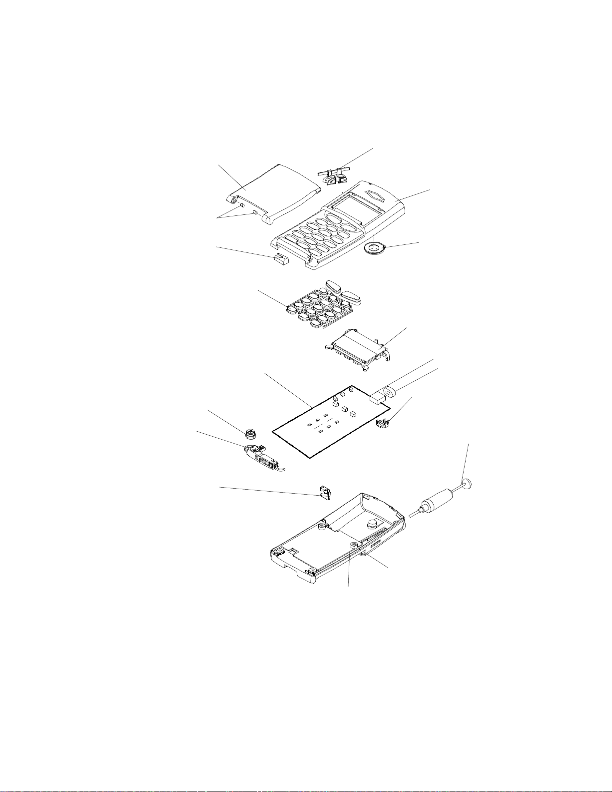
The following are the internal components of theAF738 cellular phone. See
Figure 5-2.
1. Flip
2. Side Volume Keys
3. Front Cover
4. Loudspeaker
5. LCD Display Assembly
6. Buzzer
7. Buzzer Gasket
8. Antenna Connector
9. Antenna
10. Back Cover
11. Battery Connector
12. Antenna Channel
13. System Connector
14. Microphone
15. PCB
16. Keypad
17. Microphone Duct
18. Hinge Inset
Please contact your Regional Service Manager for the latest spare parts list with part
numbers and pricing.
NOTE
The spare parts lists distributed by the Regional Service
Managers are more detailed than the information in this
manual. Please reference the item name and the phone model
when requesting spare parts information.
5-4
Page 9
Service of the Telephone EN/LZB 119 2506 R1A
1
2
3
4
5
6
7
8
9
11
18
17
16
15
14
13
12
10
Figure 5-2. AF738 Internal Components
5-5
Page 10

EN/LZB 119 2506 R1A Service of the Telephone
AF778 Internal Components
The following are the internal components of theAF778 cellular phone. See
Figure 5-3.
1. Flip
2. Side Volume Keys
3. Front Cover
4. Loudspeaker
5. LCD Display Assembly
6. Vibrator Connector
7. Buzzer
8. Buzzer Gasket
9. Antenna Connector
10. Vibrator Boot
11. Vibrator Motor
12. Antenna
13. Antenna Straw
14. Back Cover
15. Battery Connector
16. System Connector
17. Microphone
18. PCB
19. Keypad
20. Microphone Duct
21. Hinge Insets
22. Battery Connector
23. Antenna Channel
Please contact your Regional Service Manager for the latest spare parts list with part
numbers and pricing.
NOTE
The spare parts lists distributed by the Regional Service
Managers are more detailed than the information in this
manual. Please reference the item name and the phone model
when requesting spare parts information.
5-6
Page 11

Service of the Telephone EN/LZB 119 2506 R1A
2
3
4
5
6
7
8
10
11
12
14
9
13
1
21
20
19
17
16
18
15
Figure 5-3. AF778 Internal Components
5-7
Page 12

EN/LZB 119 2506 R1A Service of the Telephone
Common Telephone Failures
Refer to Table 5-2 for a list of common failures, the probable cause of the failure, and
the component to be changed.
Many failures or problems with the phone may be software-related. The first thing
that should always be checked is software version of the phone. Please ensure that
the phone has the latest version of software (contact your Regional Service Manager
for further information).
Table 5-2. Common Failures
Possible
Symptom
Failure Action
1. Phone not
getting signal
2. Top Indicator
not lit
3. Phone number
displays 1s and
0s even after
programming
4. Top LED is
always red even
though battery is
charged.
Damaged antenna
Damaged antenna
connector
Preferred system option
incorrectly set
Mask SID enabled
Damaged antenna
Damaged antenna
connector
No RF signal
See items in #1s
SUBNUMBER option is
not programmed
Is it really red or is it
orange?
Change antenna
Change back cover
Make sure option is set to
PREF SYS or PREF ONLY
(MENU 52)
Check Mask SID entries. Refer
to Chapter 4, Programming
MASK SIDs.
Replace antenna
Replace antenna connector
(Level 2 and higher only)
Ensure you are in an area with
some signal.
See items in #1
Make sure you have entered a
Mobile number in both the MIN
and SUBNUMBER fields. The
SUBNUMBER is what actually
gets displayed.
If it is really orange, the VIB
ONLY feature is enabled (AF778 only…MENU 16)
5-8
Page 13

Service of the Telephone EN/LZB 119 2506 R1A
Table 5-2. Common Failures
Possible
Symptom
Failure Action
5. I set the RING
VOL to high, but
it sometimes
gets set to low.
6. Portuguese
option is not
available in my
2 options for RING VOL,
TONE, etc.
The audio options allow for a
setting one option in handset
mode and a different one in
handsfree mode.
Certain packages only The Portuguese option is only
available in certain packaged
phones in certain markets.
phone
7. Display not lit Display Change display assembly
8. Display
Display broken Change display assembly
segments
missing
9. Display locks up Shorted LCD connections Replace LCD assembly
10. Power levels are
low
RF test adapter Make sure you are using the
proper RF test adapter with the
phone.
AF-778 RF adapter requires a
shorter gold pin (only 2mm).
Refer to Chapter 4, Figure 4-1.
11. Side Volume
Keys not
functioning
Bad soldering
Bad switch positioning
Resolder switches
Desolder and reposition
switches
12. Keypad keys not
functioning
13. Buzzer not
functioning
14. Vibrator not
functioning*
Broken switches
Exchange switches
Bad or broken keypad Exchange keypad
Bad solder at buzzer
Broken buzzer
Broken vibrator motor
Broken vibrator connector
Damaged wires from
Check and resolder
Exchange buzzer
Change vibrator motor
Change vibrator connector
Change damaged wires
vibrator connector to
vibrator motor
Damaged boot assembly
Check and replace boot
assembly
5-9
Page 14

EN/LZB 119 2506 R1A Service of the Telephone
Table 5-2. Common Failures
Possible
Symptom
Failure Action
15. Audio not
functioning
16. Phone won’t
turn on
17. Battery not
charging
Peripherals not
functioning
* On AF778 only
Sound channel at flip may
be clogged*
Contacts at system
connector may be broken
Microphone broken
Earphone broken
ON key may be damaged
System connector may be
damaged
Battery or system
connector may be
damaged
System connector may be
damaged:
Clean or exchange flip*
Check and exchange system
connector
Change microphone
Change front cover
Check/exchange keypad
Check/exchange system
connector
Check and exchange battery
Check and clean all contacts at
system connector and contact
pads on PCB
Check/exchange system
connector
5-10
Page 15

Service of the Telephone EN/LZB 119 2506 R1A
Required Tools
The following are the tools needed to perform Level 3 service on the Ericsson AF738
and AF778 cellular telephones:
• T6 Torx screwdriver
• Torque driver (20n-Cm)
• Soldering iron and flux
• Latex gloves
• Precision Fine Pliers
• Fine Tweezers
5-11
Page 16

EN/LZB 119 2506 R1A Service of the Telephone
AF738 Disassembly
See Figure 5-2 for part reference when disassembling the telephone.
NOTE
Only specific levels of Service Centers are authorized to disassemble the
telephone (please contact your Regional Service Manager). Failure to comply
with this will void the warranty of the telephone.
CAUTION
The telephone should only be opened in a dust-free area where
ESD protection is available and used (anti-static mats, wrist
straps, etc). Refer to Chapter 1.
Main Disassembly
Perform the following to disassemble the phone:
1. Remove the battery.
2. FULLY extend the antenna and remove by unscrewing it.
3. Place the phone face down on a grounded, ESD-protected surface.
4. Remove the warranty label.
NOTE
Removal and/or tampering with the warranty label by
unauthorized shops will void the warranty of the telephone.
5. Remove the four screws with a T6 Torx driver.
6. Place the telephone FACE DOWN and remove the back cover assembly by
lifting up from the bottom and pushing in a forward direction.
7. Remove the two top board screws with the T6 Torx driver. Note how the RF
connector is positioned and take care in handling it.
5-12
Page 17

Service of the Telephone EN/LZB 119 2506 R1A
AF778 Disassembly
See Figure 5-3 for part reference when disassembling the telephone.
NOTE
Only specific levels of Service Centers are authorized to disassemble the
telephone (please contact your Regional Service Manager). Failure to
comply with this will void the warranty of the telephone.
CAUTION
The telephone should only be opened in a dust-free area where
ESD protection is available and used (anti-static mats, wrist
straps, etc). Refer to Chapter 1.
Main Disassembly
Perform the following to disassemble the phone:
1. Remove the battery.
2. FULLY extend the antenna and remove by unscrewing it.
3. Place the phone face down on a grounded, ESD protected surface.
4. Remove the warranty label.
NOTE
Removal and/or tampering with the warranty label by
unauthorized shops will void the warranty of the telephone.
5. Remove the four screws with a T6 Torx driver.
6. Place the telephone FACE DOWN and remove the back cover assembly by
lifting up from the top and gently separating the back cover from the font
cover. See
CAUTION
Use care when removing the back cover so you do not damage
the vibrator wires.
5-13
Page 18

EN/LZB 119 2506 R1A Service of the Telephone
7. Gently flip the back cover assembly over so that the tops of the front and
back covers are facing each other
8. Note how the antenna guide straw is positioned in the back cover.
9. Remove the two top PCB screws with the T6 Torx driver. Note how the RF
connector is positioned and take care in handling it.
10. Gently lift the PCB assembly out of the front cover by holding the edges of
the board and lifting up.
11. Using a pair of tweezers, gently pull on the vibrator wires to disconnect them
from the vibrator connector on the PCB.
CAUTION
The earpiece speaker is permanently mounted and tuned to the
front cover assembly. DO NOT remove it or the acoustic
performance of the telephone may be compromised. If the
speaker is defective, the entire front cover assembly must be
replaced.
Figure 5-4. Separating the Front and Back Covers
5-14
Page 19

Service of the Telephone EN/LZB 119 2506 R1A
PLASTIC SNAPS
Replacing The LCD/Lightguide Assembly
Perform the following procedure to replace the lightguide assembly:
NOTE
The LCD, lightguide, and elastomer are all part of one
assembly and should be removed as such.
1. Disassemble the phone. See Disassembly, steps 1 through 7 (AF738) or steps
1 through 11 (AF778).
CAUTION
Be very careful not to damage the RF connector or the vibrator
wires.
CAUTION
Take care not to lose the rubber microphone duct when
removing the PCB assembly. Sometimes the duct sticks to the
microphone; sometimes it stays in the front cover.
2. See Figure 5-5. With a small screwdriver, gently pry the plastic snaps at the
top of the lightguide assembly away from the PCB assembly until the
lightguide assembly can be easily removed.
Figure 5-5. Removing Lightguide Assembly
3. Note the PCB revision state just under the LEDs (TVK 119 3433 RX, where
X is the revision level). See Figure 5-6.
5-15
Page 20

EN/LZB 119 2506 R1A Service of the Telephone
LCD
CONNECTOR
4. If the revision is R6 or lower, apply Kapton tape (included in
SXK 107 6524/z) over the via holes. Take care not to cover the LCD
connector pad on the PCB.
BUZZER
APPLY
KAPTON
TAPE
REVISION
LEVEL
AF738-2
KEYPAD SIDE OF BOARD
Figure 5-6. Board Revision Level
NOTE
If the revision is R9 or greater, no Kapton tape is required.
5. Remove the new LCD assembly from packaging.
CAUTION
Do not handle LCD assembly with bare hands! Use latex
gloves and have proper ESD protection.
PAD
6. Make sure the elastomer connector is properly seated in the lightguide
assembly. If the elastomer has fallen out, carefully replace it in the lightguide
with your gloved fingers. Do NOT use tweezers or handle with bare hands.
7. See Figure 5-7. Place the lightguide assembly in the bottom aligning holes in
the PCB and snap the top corners into place.
5-16
Page 21

Service of the Telephone EN/LZB 119 2506 R1A
AF-738-6
LIGHTGUIDE
ASSEMBLY
GUIDE HOLES
Figure 5-7. Replacing Lightguide Assembly
8. Visually check each corner to ensure the LCD assembly is properly seated.
9. Gently place the PCB back into the front cover.
10. Replace the antenna connector making sure the alignment pegs are in the
holes in the PCB. Torque the screws to 20n-Cm (Newton centimeters).
11. Before further assembly, test both side volume keys to make sure they
“click” when they are pressed. If not, gently re-align the rubber volume
keypad to engage the switches.
12. Reassemble the phone. See Reassembly, steps 3 to 14 (for AF738) or steps 1
through 11 (for AF778).
13. Turn the phone on.
14. Verify that all segments and characters work on the LCD. If segments are not
present, disassemble the phone and repeat steps 7 and 8. Check position of
elastomer for proper seating.
15. Click the volume keys to ensure proper operation.
5-17
Page 22

EN/LZB 119 2506 R1A Service of the Telephone
Replacing the Vibrator Motor Assembly (AF778 Only)
Perform the procedures in the following sections to replace the vibrator motor
assembly.
Replacing the Vibrator Motor
Perform the following procedure to replace the vibrator motor. See Figure 5-8.
24. Disassemble the phone. See AF778 Disassembly, steps 1 through 11.
25. Align open side of the rubber boot on the vibrator motor assembly toward the
keypad of the phone with the vibrator wires facing toward the antenna guide
straw.
26. Insert the motor assembly into the rear cover.
NOTE
The motor assembly fits snugly into the two guides in the back
cover.
27. Visually inspect the motor assembly installation to assure that the motor
counter-weight is not contacting the rear cover.
28. Tuck all of the slack wire into the rear cover.
29. Using the self-adhesive foam pad, adhere the slack wire to the rear cover.
30. Reassemble the phone. See AF778 Assembly, steps 1 through 12.
5-18
CAUTION
Check during reassembly that the wires from the vibrator
motor assembly do not become pinched or nicked.
Page 23

Service of the Telephone EN/LZB 119 2506 R1A
VIBRATOR
VIBRATOR
MOTOR
RUBBER
BOOT
REAR
COVER
WIRES
Figure 5-8. Vibrator Motor Assembly
Replacing the Vibrator Connector
Perform the following procedure to replace the vibrator connector. See Figure 5-3.
1. Disassemble the phone. See AF778 Disassembly, steps 1 through 10.
2. Use the tweezers to detach the wire assembly from the vibrator connector on
the PCB.
3. Desolder the vibrator connector from the PCB.
4. Solder a new vibrator connector onto the PCB.
5. Reassemble the phone. See AF778 Assembly, steps 1 through 12.
CAUTION
Check during reassembly that the wires from the vibrator
motor assembly do not become pinched or nicked.
5-19
Page 24

EN/LZB 119 2506 R1A Service of the Telephone
Replacing the Vibrator Wires
The vibrator wires are part of the vibrator motor assembly. If the wires become
damaged, the entire motor assembly must be replaced.
Replacing the Keypad
Perform the following procedure to remove the keypad:
1. Disassemble the phone. See Disassembly, steps 1 through 7 (AF738) or steps
1 through 11 (AF778).
2. To remove the keypad, simply pull it off the PCB.
3. Re-position the keypad into the front cover, not the PCB. This will ensure
proper alignment when putting the main assembly back together.
Replacing the System Connector
Perform the following procedure to remove the system connector. See Figure 2-4.
1. Disassemble the phone. See Disassembly, steps 1 through 7 (AF738) or steps
1 through 11 (AF778).
2. Gently pull the system connector back and forth until it comes off the PCB.
Note the way it was positioned.
3. Carefully hold the PCB by the edges and re-install system connector by
pushing onto the PCB.
CAUTION
Be careful not to reinstall the system connector upside down.
5-20
Page 25

Service of the Telephone EN/LZB 119 2506 R1A
Reassembly
NOTE
The reassembly procedures for each phone model are unique
to that model. Be sure to follow the correct procedure when
reassembling the phone.
AF738 Reassembly
Perform the following procedure to reassemble the phone. Refer to the Torquing
Instruction section.
1. Carefully place the PCB into the front cover and align the top screw holes.
2. Re-install the antenna connector and two Torx screws. Torque the screws to
20 Ncm. Make certain that the antenna connector is correctly positioned.
Replace the antenna connector if it is damaged or bent.
CAUTION
DO NOT OVERTIGHTEN THE SCREWS! Be sure to use a
calibrated Torx screwdriver and torque the screws to 20 Ncm.
3. With the front cover assembly FACE DOWN, reinstall the back cover.
4. Carefully hook the top edge of the front and back covers. Push down on the
back cover until closed.
5. Check to see that there is a consistent gap all around the phone.
6. Re-install the four Torx screws.
7. Torque the screws to 20 Ncm. Refer to the Torquing Instruction section.
8. Apply a new warranty seal to the bottom right corner of the back cover,
covering the screw. Be sure to adequately cover the screw hole.
5-21
Page 26

EN/LZB 119 2506 R1A Service of the Telephone
NOTE
Make sure to use the Yellow warranty label. The yellow
label indicates a low voltage phone and is color-coded to
accessory packaging.
9. With the antenna FULLY extended, reinstall by screwing into the RF port.
Tighten only until the threads stop.
10. Retract and extend the antenna to check for smooth movement.
11. Reinstall the battery.
12. Power the phone up and make a test call to ensure proper reassembly. Check
for LCD, keypad, speaker, and microphone operation as well as proper RSSI
level.
AF778 Reassembly
Perform the following procedure to reassemble the AF778. Refer to the Torquing
Instruction section.
1. Plug the male connector head of the vibrator wires into the vibrator
connector on the PCB. The side of the male connector head with the exposed
wires goes down against the PCB.
2. Carefully place the PCB into the front cover and align the top screw holes.
3. Re-install the antenna connector and two Torx screws. Torque the screws to
20 Ncm.
4. Make certain that the antenna connector is correctly positioned. If damaged
or bent, replace the antenna connector.
CAUTION
DO NOT OVERTIGHTEN THE SCREWS! Be sure to use a
calibrated Torx screwdriver and torque the screws to 20 Ncm.
5. With the battery housing side of the back cover assembly FACE DOWN,
place the front cover assembly onto the back cover assembly.
6. Hook the bottom edges of the front and back cover assemblies together.
7. While holding the bottom of the phone, check the gap at the top of the phone
to ensure that the vibrator wires are not protruding out of the top of the
phone.
8. Carefully snap the front and back covers together.
9. Check to see that there is a consistent gap all around the phone.
5-22
Page 27

Service of the Telephone EN/LZB 119 2506 R1A
CAUTION
Check during reassembly that the wires from the vibrator
motor assembly do not become pinched or nicked.
10. Reinstall the four Torx screws.
11. Torque the screws to 20 Ncm. Refer to the Torquing Instruction section.
12. Apply a new warranty seal to bottom right corner of the back cover, covering
the screw. Be sure to adequately cover the screw.
NOTE
Make sure to use the Yellow warranty label. The yellow
label indicates a low voltage phone and is color-coded to
accessory packaging.
13. With the antenna FULLY extended, re-install by screwing into the RF port.
Tighten only until the threads stop.
14. Re-install the battery.
13. Power the phone up and make a test call to ensure proper re-assembly. Check
for LCD, keypad, speaker, and microphone operation as well as proper RSSI
level.
5-23
Page 28

EN/LZB 119 2506 R1A Service of the Telephone
1
3
Torquing Instructions
Reassembly of the phone requires torquing of the screws in the back cover.
The four screws holding the back cover to the front cover must be torqued to 20
Ncm. See Figure 5-9 for the torquing sequence. A special Torque driver is available
from Spare Parts.
NOTE
Torque each screw twice by repeating the complete sequence.
Torquing is critical to performance, so radio must be re-tested
afterwards.
2
4
Figure 5-9. Torquing Sequence
Return to Service Checkout
Perform a visual check and an on-the-air call to check out the phone before returning
it to service.
5-24
 Loading...