

Page 1

Accessories EN/LZB 119 2506 R1A
Chapter 3
Accessories
Ericsson Cellular Phone AF738
AF778
i
Page 2

EN/LZB 119 2506 R1A Accessories
SUBJECT .................................................................................... PAGE
Introduction.........................................................................................................3-1
Table 3-1. Accessories...................................................................................3-1
Belt Clip Installation ...........................................................................................3-2
Figure 3-1. Belt Clip Installation....................................................................3-2
Battery Information ............................................................................................3-3
Figure 3-2. 650 mA Nickel Metal Hydride (NiMH) Battery ...........................3-3
Battery Replacement ......................................................................................3-4
Figure 3-3. Removing the Battery ..................................................................3-4
Figure 3-4. replacing the Battery....................................................................3-4
Connector Information...................................................................................3-5
Figure 3-5. Battery Connector........................................................................3-5
Table 3-2. Battery Connector Signals.............................................................3-5
Battery Chargers.................................................................................................3-6
Table 3-3. Battery Charger Features...............................................................3-6
Rapid Charger................................................................................................3-7
Figure 3-6. Rapid Charger..............................................................................3-7
Installation.....................................................................................................3-7
Figure 3-7. Installing the Standard Charger....................................................3-7
Figure 3-8. Detaching the Standard Charger...................................................3-8
Connector and Signals ...................................................................................3-8
Figure 3-9. Connector....................................................................................3-8
Table 3-4. Connector Signals.........................................................................3-8
Rapid Charger Specifications.........................................................................3-9
Travel Charger...............................................................................................3-9
Installation.....................................................................................................3-9
Figure 3-10. travel Charger............................................................................3-9
Connectors and Signals................................................................................3-10
Figure 3-11. Travel Charger Connector........................................................3-10
Table 3-5. Connector Signals.......................................................................3-10
Travel Charger Specifications......................................................................3-10
Desk Top Charger........................................................................................ 3-11
Figure 3-12. Desk Top Charger ....................................................................3-11
Installation...................................................................................................3-12
Figure 3-13. Desk Top Charger Installation.................................................. 3-12
Connectors and Signals................................................................................3-13
Figure 3-14. Connector................................................................................3-13
Table 3-6. Connector Signals.......................................................................3-13
Desk Top Charger Specifications.................................................................3-13
ii
Page 3

Accessories EN/LZB 119 2506 R1A
SUBJECT .................................................................................... PAGE
Vehicle Power and Charge.......................................................................... 3-14
Installation.................................................................................................. 3-14
Figure 3-15. Vehicle Power and Charge Installation....................................3-14
Connectors and Signals...............................................................................3-14
Vehicle Power and Charge Specifications.................................................... 3-14
Portable Handsfree Unit ................................................................................... 3-15
Figure 3-16. Portable Handsfree Unit.......................................................... 3-15
Installation ................................................................................................ 3-16
Connectors and Signals...............................................................................3-16
Figure 3-17.Connectors............................................................................... 3-16
Table 3-7. Connector Signals ...................................................................... 3-16
Portable Handsfree Unit Specifications ....................................................... 3-17
Vehicle Handsfree Kit....................................................................................... 3-18
Figure 3-18. Vehicle Handsfree Kit............................................................. 3-18
HandsFree Features..................................................................................... 3-19
Table 3-8. Vehicle Handsfree Kit Features .................................................. 3-19
Cradle......................................................................................................... 3-19
Cradle Cables.............................................................................................. 3-20
Stick-On Microphone .................................................................................. 3-20
External Speaker......................................................................................... 3-20
HF-7600 Functional Description ................................................................. 3-20
Microphone Amplifier ................................................................................ 3-21
Speaker Amplifier....................................................................................... 3-21
Modem/Handset Option.............................................................................. 3-21
Audio Switch Control ................................................................................. 3-21
External Audio Control...............................................................................3-22
Music Mute Control.................................................................................... 3-22
Power Supply.............................................................................................. 3-22
Phone Operation ......................................................................................... 3-23
Battery Charger........................................................................................... 3-23
Figure 3-19. Vehicle Handsfree Kit Block Diagram .................................... 3-23
Optional Accessories................................................................................... 3-24
Music Mute................................................................................................. 3-24
Goose-Neck Microphone............................................................................. 3-24
Data Extension ............................................................................................ 3-24
External Handset ......................................................................................... 3-24
Speaker Path............................................................................................... 3-24
Installation.................................................................................................. 3-25
Figure 3-20. Vehicle Handsfree Kit Connectors .......................................... 3-25
Table 3-9. Vehicle Handsfree Kit Connections............................................3-25
Figure 3-21. Cradle Mount Installation........................................................ 3-26
iii
Page 4

EN/LZB 119 2506 R1A Accessories
SUBJECT .................................................................................... PAGE
Figure 3-22. Cradle Installation ....................................................................3-26
Figure 3-23. Securing the Cradle to the Cradle Mount..................................3-27
Figure 3-24. Connecting the Cradle to the Vehicle Handsfree Unit...............3-27
Figure 3-25. Vehicle Handsfree Installation ................................................. 3-29
Connector and Signals .................................................................................3-30
Cradle Connector.........................................................................................3-30
Figure 3-26. Cradle Connector.....................................................................3-30
Table 3-10. Cradle Connector Signals..........................................................3-30
Power Connector .........................................................................................3-31
Figure 3-27. Power Connector .....................................................................3-31
Table 3-11. Power Connector Signals...........................................................3-31
Modular Connector......................................................................................3-32
Figure 3-28. Modular Connector..................................................................3-32
Table 3-12. Modular Connector Signals.......................................................3-32
Music Mute Connector ................................................................................ 3-33
Figure 3-29. Music Mute Connector ............................................................3-33
Table 3-13. Music Mute Connector Signals ..................................................3-33
Vehicle Handsfree Kit Specifications........................................................... 3-34
iv
Page 5

Accessories EN/LZB 119 2506 R1A
Introduction
This chapter describes the accessories used with the Ericsson AF738 and AF778
cellular telephones.
Repair of accessories consists of swapping suspected bad units with new and sending
the bad unit to the manufacturer for repair or replacement.
Refer to Table 3-1 for a list of available accessories.
Table 3-1. Accessories
Accessory Name Model Number
NiMH Battery (650 mA) NM-7065
Rapid Charger * SC-6000
Vehicle Power and Charge VP-6000
Desk Top Charger * MC-7000
Travel Charger TC-6000
Portable Handsfree Unit PO-6000
Vehicle Handsfree Solution (Semi-Duplex) HF-7300
Vehicle Handsfree Solution (Full-Duplex) HF-7600
Mobile Office Solution AC28
Mobile Data Cable Kit RPM 113 2057/55
* Note: This model has different part numbers depending on the electrical
requirements in the country used. Contact your Regional Service
Representative for more information.
3-1
Page 6
EN/LZB 119 2506 R1A Accessories
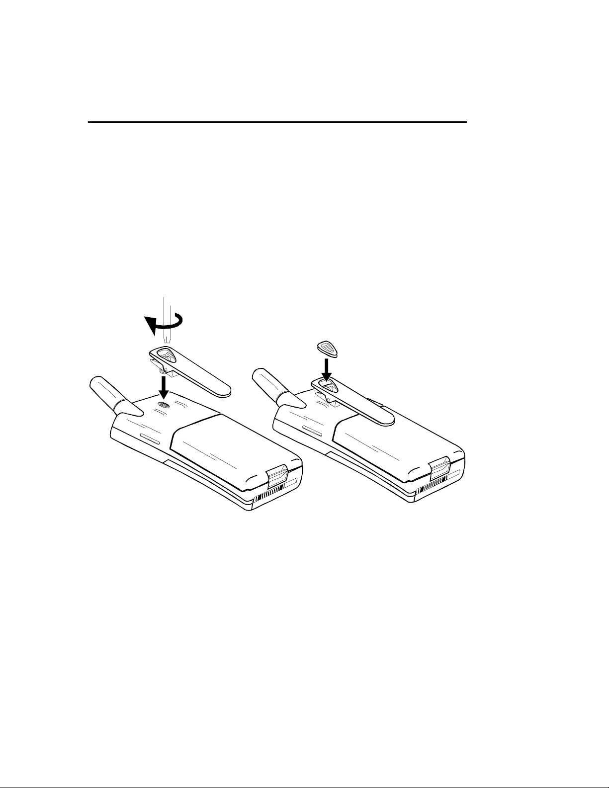
Belt Clip Installation
Perform the procedures in this section to install the belt clip. See Figure 3-1.
1. Place the phone on a flat surface, battery side up.
2. Remove rubber plug from hole in back of phone.
3. Align the belt clip with the back of the phone.
4. Using a Phillips-head screwdriver, tighten the screw in to the back of the
phone.
5. Place the rubber plug back into the clip.
3-2
Figure 3-1. Belt Clip Installation
Page 7
Accessories EN/LZB 119 2506 R1A
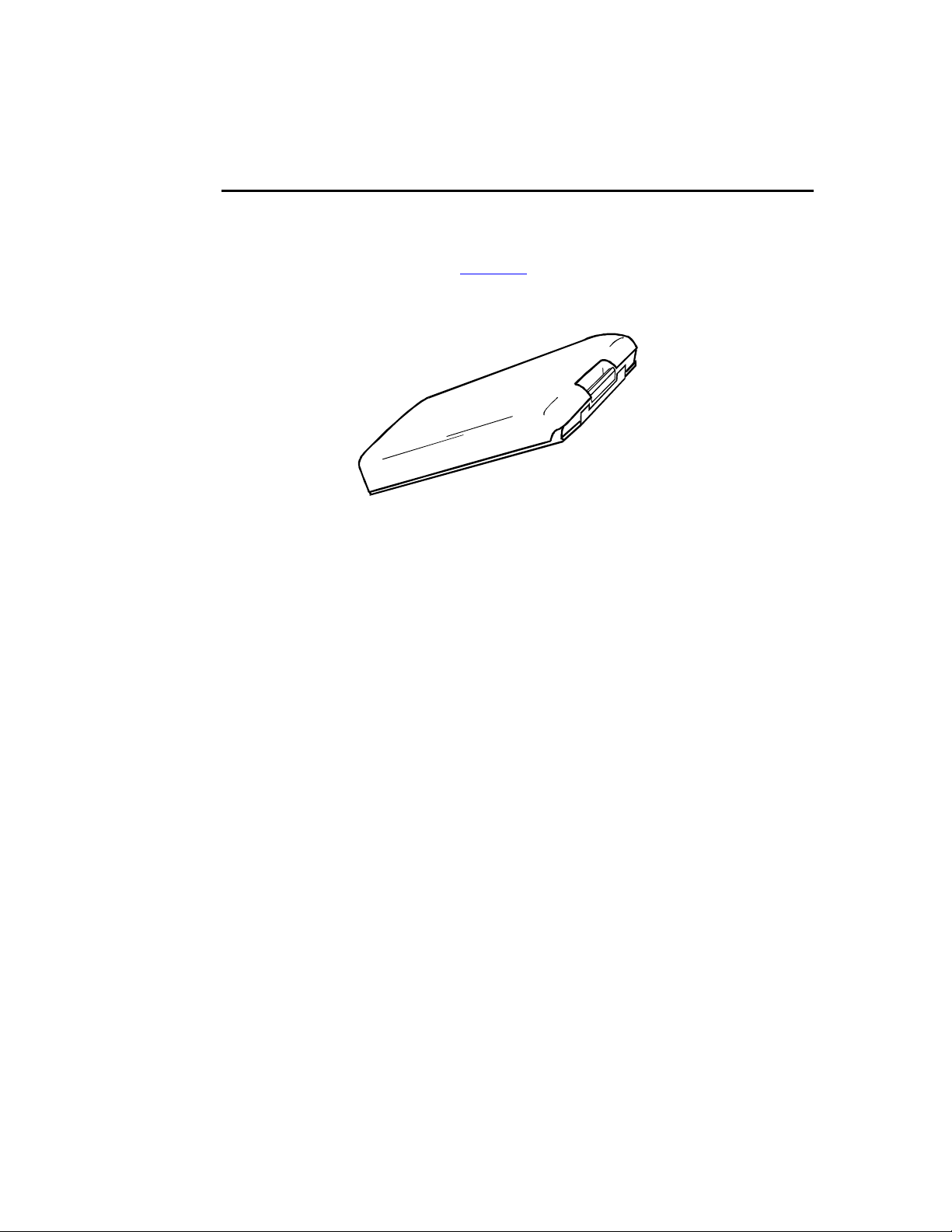
Battery Information
The Ericsson AF738 and AF778 cellular telephones use a 650 mA Nickel Metal
Hydride (NiMH) battery. Refer to Chapter 2 for charging information. See
Figure 3-2.
Figure 3-2. 650 mA Nickel Metal Hydride (NiMH) Battery
3-3
Page 8
EN/LZB 119 2506 R1A Accessories
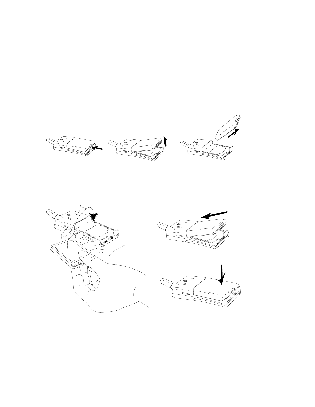
Battery Replacement
Perform the following procedure to remove and replace the battery:
1. Press in at the bottom of the battery and lift up. See Figure 3-3.
2. Insert the battery pack into the telephone and push until you hear a click. See
Figure 3-4.
a
b c
Figure 3-3. Removing the Battery
a
b
c
3-4
Figure 3-4. Replacing the Battery
Page 9

Accessories EN/LZB 119 2506 R1A
1
3
Connector Information
See Figure 3-5 and Table 3-2 for battery connector information.
-
+
2
Figure 3-5. Battery Connector
Table 3-2. Battery Connector Signals
Pin Signal
1 Ground
2 No Used
3 + 4.8 Vdc
3-5
Page 10

EN/LZB 119 2506 R1A Accessories
Battery Chargers
The phone features a microprocessor for control of battery charging through the
charger. The phone’s LCD display indicates the status of the charging process. Refer to
Chapter 2 for charging information.
Refer to Table 3-3 for a description of the battery chargers used with the AF738 and
AF778 Cellular Phones.
Table 3-3. Battery Charger Features
Feature Battery Charger
Rapid-charges the battery.
All chargers
Provides power to the telephone at the same
time as battery charging.
Automatic trickle charge after main charge is
complete.
Compact and lightweight
Detachable AC cord for various markets
Detachable AC connector for various
markets.
Travel Charger
TC-6000
Desk Top Charger MC-
7000
Can discharge battery.
Can charge two batteries.
Accessory connection in back of unit.
Allows battery charging from the 12V or 24V
cigarette lighter outlet.
Vehicle Power and
Charge
VP-6000
Allows handsfree operation while charging. Vehicle HandsFree Kit
HF-7300
HF-7600
* Note: This model is only provided in the original telephone package. It is
not sold separately.
3-6
Page 11
Accessories EN/LZB 119 2506 R1A
CONNECTOR
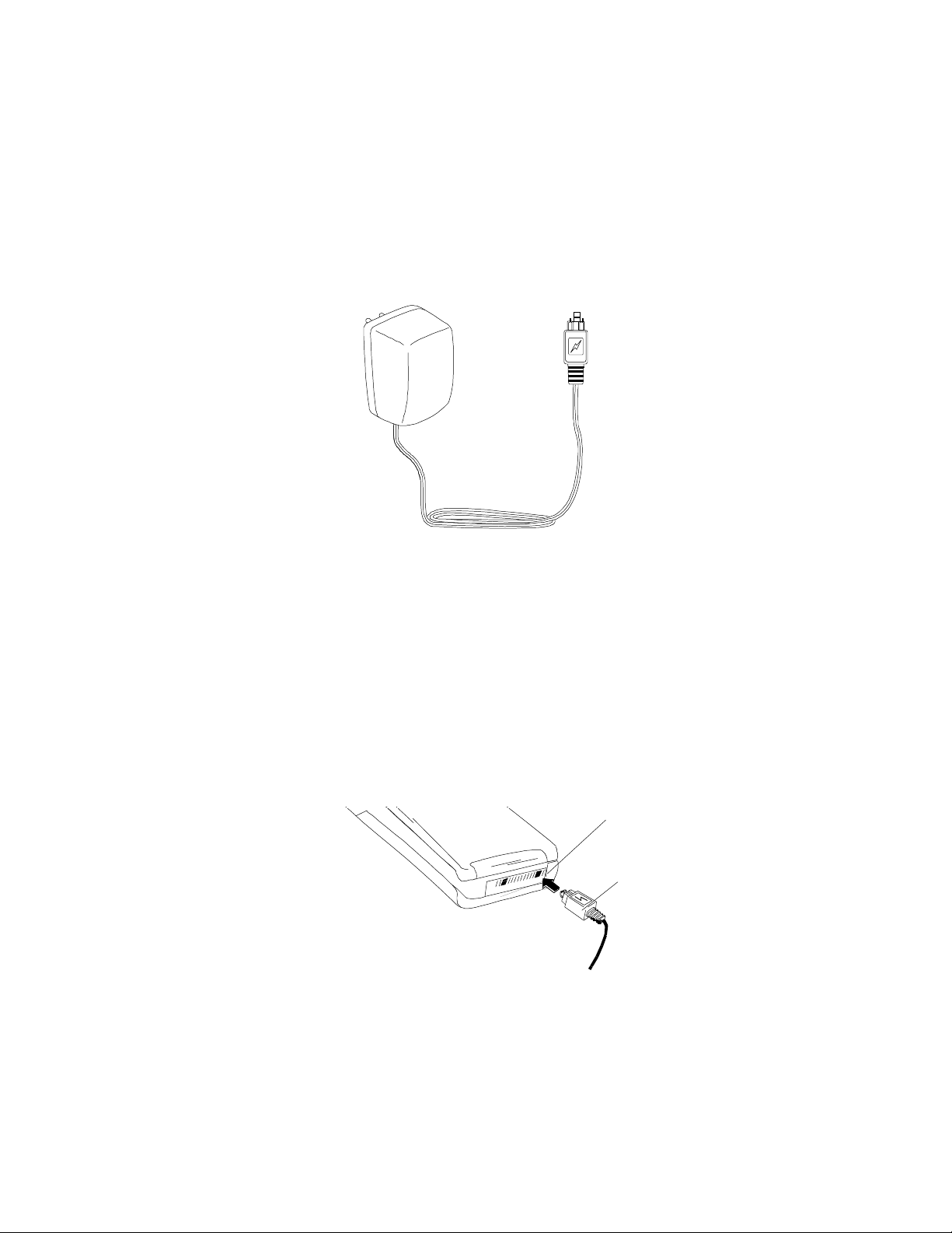
Rapid Charger
The rapid charger is only available in some telephone packages. It is not sold
separately.
Figure 3-6. Rapid Charger
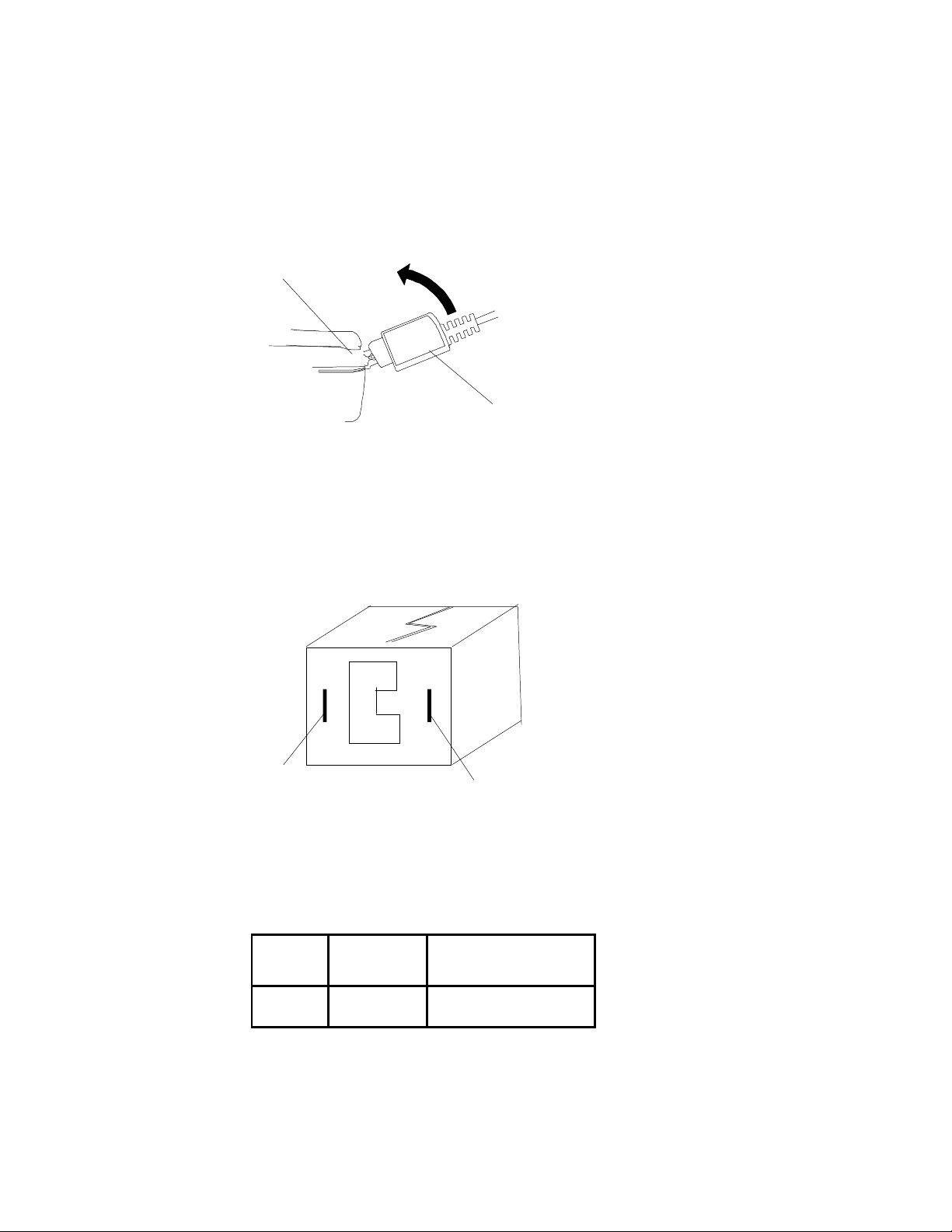
Installation
To install the rapid charger on the phone, plug the connector, flat side up, into the
phone’s system connector. Then plug the charger’s main connector into an AC wall
socket. See Figure 3-7.
NOTE
The flat side of the charger connector is marked with a
lightning bolt.
SYSTEM
CHARGER
CONNECTOR
Figure 3-7. Installing the Standard Charger
3-7
Page 12
EN/LZB 119 2506 R1A Accessories
SYSTEM
To detach the charger from the phone, gently pull it up and out from the system
connector. See Figure 3-8.
CONNECTOR
CHARGER
CONNECTOR
Figure 3-8. Detaching the Standard Charger
Connector and Signals
See Figure 3-9 and Table 3-4 for connector and signal information for the standard
charger.
1
Figure 3-9. Connector
Table 3-4. Connector Signals
Fig.
Ref. Signal Description
1 DGND Digital Ground
2 DCIO Supply to the phone
3-8
Page 13

Accessories EN/LZB 119 2506 R1A
Dimensions
Ambient Temperature
Charging Time:
Rapid Charger Specifications
135 x 50 x 28 cm
Input AC120V 60Hz 10W
Output DC6V 250mA
+ 5° to + 48° C
< 2 hrs.
Travel Charger
The Travel Charger shares the functionality and installation as the Rapid Charger.
Installation
To install the travel charger on the phone, plug the connector, flat side up, into the
outside socket at the phone’s system connector. Then plug the charger’s main
connector into any wall socket. See Figure 3-10.
FROM
POWER
SOURCE
TO
SYSTEM
CONNECTOR
Figure 3-10. Travel Charger
3-9
Page 14

EN/LZB 119 2506 R1A Accessories
DC Cable Length
Output
Charging Time
Connectors and Signals
See Figure 3-11 and Table 3-5 for connector and signal information for the travel
charger.
1
Figure 3-11. Travel Charger Connector
Table 3-5. Connector Signals
Fig.
Ref. Signal Description
1 DGND Digital Ground
2 DCIO Supply to the phone
Travel Charger Specifications
Ambient Temperature + 5 C to +48 C
2 meters
Input 100 - 240 VAC 50-60 Hz
7.6V 600mA
Approx. 2.5 hours
3-10
Page 15

Accessories EN/LZB 119 2506 R1A
FRONT SLOT LED
Desk Top Charger
See Figure 3-12. While in the front slot of the desktop charger, the phone may be
powered ON or OFF. The rear slot provides charging for an additional battery as
well as reconditioning. The reconditioning consists of draining the battery of its
charge, then recharging it to full capacity before illuminating the "green" LED.
SPARE
BATTERY
TO POWER
REAR SLOT LED
Figure 3-12. Desk Top Charger
NOTE
The rear slot LED flashes when the battery in the rear slot is
discharging.
3-11
Page 16

EN/LZB 119 2506 R1A Accessories
Installation
Perform the following procedure to install the DeskTop Charger. See Figure 3-13.
1. Insert the connector from the power cord into the back of the charger.
2. Plug the power cord into the wall socket.
3. Place the phone and/or the spare battery into the charger.
3-12
Figure 3-13. Desk Top Charger Installation
NOTE
The DeskTop Charger also supplies the connection for
portable hands-free use or data connections on the system
connector in the rear of the charger base.
Page 17

Accessories EN/LZB 119 2506 R1A
Ambient Temperature
Rear Slot
Connectors and Signals
See Figure 3-14 and Table 3-6 for connector and signal information for the DeskTop
Charger.
1
Figure 3-14. Connector
Table 3-6. Connector Signals
Fig.
Ref. Signal Description
1 DGND Digital Ground
2 DCIO Supply to the phone
Desk Top Charger Specifications
Output 7.6V 600mA
Front Slot
Charging Time Approx. 2.5 hours
Charging time Approx. 2.5 hours
Reconditioning time: N/A
2
Input 100 - 240 VAC 50-60 Hz
+ 5 C to +48 C
3-13
Page 18

EN/LZB 119 2506 R1A Accessories
Dimensions (AC/DC)
Cable Length
CIGARETTE
Vehicle Power and Charge
The Vehicle Power and Charge allows the phone to be powered and charged through
a standard vehicle cigarette lighter.
Installation
Perform the following procedure to install the Vehicle Power and Charge. See Figure
3-15.
1. Insert the cigarette lighter adapter into the cigarette lighter of the vehicle.
2. Insert the charging connector into the back of the phone.
LIGHTER
ADAPTER
CHARGING
CONNECTOR
Figure 3-15. Vehicle Power and Charge Installation
Connectors and Signals
The vehicle power and charger uses the same connectors and signals as the Travel
Charger. See Figure 3-11 and Table 3-5.
Vehicle Power and Charge Specifications
90 x 28 mm
Dimensions (Connector) 50 x 23 x 20 mm
Input 10.8 – 15.6 VDC
1.9 m
Ambient Temperature
+ 10° to 45° C
Charging time Approx. 1 hour
3-14
Page 19

Accessories EN/LZB 119 2506 R1A
EARPIECE
Portable Handsfree Unit
The portable handsfree unit allows the operator to use the phone while performing
other tasks. See Figure 3-16.
PHONE
CONNECTOR
Figure 3-16. Portable Handsfree Unit
3-15
Page 20

EN/LZB 119 2506 R1A Accessories
PORTHF
2
Installation
Perform the following procedure to install the portable handsfree unit. See
Figure 3-16.
1. Plug the connector from the portable handsfree unit into the system
connector on the phone.
2. Place the earphone in your ear.
3. Attach the phone to your belt or place it on a stable surface.
Connectors and Signals
See Figure 3-17 and Table 3-7.
1
FRONT SIDE
3
4
1 3 42
Figure 3-17. Connectors
Table 3-7. Connector Signals
Pin Signal Type Color
1 AFMS Speaker signal (+) Green
2 ATMS Microphone signal (+) Red
3 AGND Ground (mic/speaker (-)) Natural / clear
4
Sense signal Connected to AGND
3-16
Page 21

Accessories EN/LZB 119 2506 R1A
Earphone:
Microphone:
Impedance
Portable Handsfree Unit Specifications
Input Power Rated 1mW
Impedance 150 ohm +/- 25%
Directivity Omnidirectional
Sensitivity -43.5 dB measured at supply voltage
3.3V (0 dB = 1V/Pa at 1kHz)
Min 50 ohm, max 2.2 kohm
measurement circuit
Signal-to-Noise ratio Min 45dB (1Pa 1kHz)
3-17
Page 22

EN/LZB 119 2506 R1A Accessories
Vehicle Handsfree Kit
The Vehicle Handsfree Kit provides a convenient and easy way to use the phone in a
vehicle. The kit provides power to the phone from the vehicle battery, charges the
phone’s battery, and includes a microphone and speaker for handsfree use. See
Figure 3-18.
The Vehicle Handsfree Kit includes:
• Handsfree Unit
• Handsfree Cradle
• Cradle Mounting Bracket
• Microphone
• External Speaker
• Power Cable
• Fuse Kit
• Wire Tie
The following are optional accessories for the Vehicle Handsfree Kit:
• Music mute cable
• Advanced music mute
• Vehicle data adapter
• External handset
• Goose-neck microphone
3-18
NOTE
These accessories may not be available in all areas or markets.
Figure 3-18. Vehicle Handsfree Kit
Page 23

Accessories EN/LZB 119 2506 R1A
HandsFree Features
Refer to Table 3-8. The HF-7300 HandsFree Unit does not include a Digital Signal
Processor (DSP), as the Central Processing Unit (CPU) of the telephone handles the
handsfree switching. The HF-7600 HandsFree Unit contains a DSP. Refer to the
HF-7600 Functional Description.
The handsfree function is semi-duplex, which only permits one party to talk at a time
while the other party is switched off to avoid feedback. When the land side party is
talking, a "comfort noise" is added to simulate the background noise heard from the
mobile.
Table 3-8. Vehicle Handsfree Kit Features
Model Number
Features
HF-7300 New amplifier and speaker for better sound performance
Uses phone’s internal HF algorithm
Semi-duplex conversation
Comfort noise
Phone-controlled charging
HF-7600 New amplifier and speaker for better sound performance
Full duplex conversation
Adaptive echo cancellation
Noise reduction
Compatible with AMPS, DAMPS, GSM, 800, 900, 1900
Cradle
The cradle consists of two sub-units, the Cradle Attachment and the Holder. The
Cradle is equipped with a slide joint which is adjusted during the installation to a
suitable vertical and horizontal angle for easy reach of the phone. The snap/click-in
holder connects the phone to the HandsFree Unit. See Figure 3-21 to Figure 3-25.
3-19
Page 24

EN/LZB 119 2506 R1A Accessories
Cradle Cables
One of the two Cradle Cables connects the system connector of the phone to the
HandsFree Unit.
Stick-On Microphone
The Stick-On Microphone included in the kit is a unidirectional microphone to be
mounted in a fixed position in the vehicle and connected to the HandsFree Unit.
External Speaker
Unless an optional Music Mute unit is used, the 4Ω External Speaker must be
connected to the speaker amplifier output of the HandsFree Unit.
NOTE
The ringer and some tones are emitted from the buzzer inside
the phone. Therefore, these tones will not be heard in the
external speaker. Refer to page 2-24.
HF-7600 Functional Description
See Figure 3-19. The HandsFree Unit includes the following electronic blocks:
• Microphone Amplifier
• Speaker Amplifier
• Modem/Handset Option
• Audio Switch Control
• External Audio Control
• Music Mute Control
• Power Supply
3-20
Page 25

Accessories EN/LZB 119 2506 R1A
Microphone Amplifier
The Microphone Amplifier has two individual inputs for the two types of available
microphones:
• Stick-On microphone (standard)
• Goose-Neck microphone (optional)
The microphone signal passes through two amplifier stages, which results in a total
gain of 31dB and 21dB for the Stick-On and GooseNeck microphone, respectively.
Speaker Amplifier
The Audio from Mobile Station (AFMS) signal received from the phone is amplified
by a programmable gain amplifier and fed to a differential amplifier consisting of
four power transistors resulting in a total gain of 21dB. To protect the power
transistors and the speaker against high current, a feed back signal from the power
transistors to the programmable amp will allow only short peaks of high current to
get through but reduce continuous high current to approximately 1.2A corresponding
to just about 5W output power.
Modem/Handset Option
The Data Communication connector can be utilized for connection of two different
options:
• Analog PCMCIA modem
• External handset
When any of these devices is connected, the audio signal Audio to Mobile Station
(ATMS) is switched to this connector, while AFMS always is available.
NOTE
A Data Extension Unit is required for the connection between
the optional unit and the Data Communication connector.
Audio Switch Control
The Audio Multiplexer Control is used to switch the audio paths between the external
microphone and the modem/handset connector. Control signals such as external
audio control (EXTAUD) and inverted mute (MUTEINV) are derived from logical
gates controlled by the signals portable handsfree (PORTHF), data/voice (DV), and
hook sense (HOOKSNS).
External Audio Control
3-21
Page 26

EN/LZB 119 2506 R1A Accessories
The EXTAUD signal informs the phone when an accessory which is using the two
external audio signals AFMS and ATMS has been connected to the HandsFree Unit
Music Mute Control
An optional Music Mute unit can be supplied with +12V from the vehicle battery.
The Music Mute function is controlled from the phone by the MUTE signal, which is
inverted by an open collector transistor before becoming available at two of the
connectors.
Power Supply
The Handsfree Unit is able to deliver power to the phone for operation and battery
charging by regulating the +12V of the vehicle battery to a constant current supply of
maximum 850mA and less than 1mA during stand-by.
3-22
Page 27

Accessories EN/LZB 119 2506 R1A
Phone Operation
The power consumption of the phone in different situations, e.g. in stand-by or in
transmission, is entirely controlled by the phone itself, as these power levels are
programmed and stored in the phone.
Battery Charger
As the phone battery at all times is provided with current from the HandsFree Unit,
the phone itself controls the charging of the battery, including trickle charging. For
more information regarding the battery charging algorithms of the telephone, refer to
Chapter 2.
DSP
IC301
MIC
J4
FLASH
EPROM
MEMORY
IC202
CPU
IC201
SPKR
J7
PWR OP AMP
IC303
MMUTE
J5
DATA
J6
CRADLE
ATMS
TO PHONE SYSTEM
DCIO
IC102
PWR
J1
J2
AFMS
Figure 3-19. Vehicle Handsfree Kit Block Diagram
3-23
Page 28

EN/LZB 119 2506 R1A Accessories
Optional Accessories
Music Mute
An optional Music Mute unit can be connected to the HandsFree Unit and will direct
the amplified received audio signal to the car stereo speakers during the handsfree
conversation. If the car stereo is equipped with a specific “mute” input, the optional
Music Mute Cable connected directly between this input and the HandsFree Unit will
mute the car stereo during the handsfree conversation.
Maximum current load at Music Mute output is 200mA.
Goose-Neck Microphone
A GooseNeck Microphone allows a more flexible microphone position for improved
sound quality including reduction of transmitted noise.
Data Extension
Data communication using handsfree mode is made possible by connecting a Data
Extension Unit between a modem and the Data Communication Connector.
External Handset
An External Handset will give the user the possibility to switch from handsfree to
handheld operation without disconnecting the external antenna and the power source.
A Data Extension Unit is required for the connection between the External Handset
and the Data Communication Connector.
The vehicle handsfree kit includes an electronics box (which contains electronics for
speaker and microphone amplifiers, power supply and charging), a phone cradle, and
an external speaker and microphone.
All external connectors are on one side of the electronics box to facilitate easy
installation of all cables. An external antenna adapter cable is available to enhance
reception.
In the HF-7300, there is no handsfree processor in the holder. The microprocessor in
the telephone controls all the handsfree switching.
Speaker Path
A 3W audio amplifier feeds the speaker. The external 5W speaker has a 4-ohm
impedance. The volume is adjusted from the telephone.
3-24
Page 29

Accessories EN/LZB 119 2506 R1A
Installation
The Vehicle Handsfree Kit has the connections shown in Figure 3-20. Refer to
Table 3-9 for connection information.
J4
J7
J5
J6
J1
J2
Figure 3-20. Vehicle Handsfree Kit Connectors
Table 3-9. Vehicle Handsfree Kit Connections
Connector Connects To
J1 Cradle
J2 Power
J4 Microphone
J5 Music Mute
J6 Data Communications
J7 Speaker
3-25
Page 30

EN/LZB 119 2506 R1A Accessories
Perform the following procedure to install the Vehicle Handsfree Kit. See Figure 321 through Figure 3-25 throughout this procedure.
1. Mount the cradle mount onto a flat surface in the vehicle, within reach of
the user. See Figure 3-22, position 1.
2. Insert the supplied screw through the slot on the cradle. See
Figure 3-22, position 2.
3. Slide the cradle onto the mount. See Figure 3-23.
4. Tighten the screw in the cradle slot to secure the cradle to the cradle
mount, and place plastic shied over the screw. See Figure 3-23.
5. Connect the cradle to the Vehicle HandsFree Unit using the cradle
connector cable. See Figure 3-24.
3-26
Figure 3-21. Cradle Mount Installation
Figure 3-22. Cradle Installation
Page 31

Accessories EN/LZB 119 2506 R1A
Figure 3-23. Securing the Cradle to the Cradle Mount
Figure 3-24. Connecting the Cradle to the Vehicle Handsfree
Unit
3-27
Page 32

EN/LZB 119 2506 R1A Accessories
6. Mount the speaker in the vehicle. See Figure 3-25.
NOTE
The speaker must be mounted at least 50 cm away from the
phone.
7. Mount the microphone in the vehicle. See Figure 3-25.
NOTE
The microphone must be mounted as close to the user’s mouth
as possible.
8. Connect the Vehicle Handsfree Kit to the power source. See Figure 3-25.
NOTE
Power must be taken from the vehicle’s battery terminal
directly.
3-28
Page 33

Accessories EN/LZB 119 2506 R1A
3.9m
Min 50 cm
J2
3A
J1
J7
J4
2.0m
4.0M
J6
J5
+12V
Figure 3-25. Vehicle Handsfree Installation
* Refer to Table 3-9 for connection information.
3-29
Page 34

EN/LZB 119 2506 R1A Accessories
1
12
Connector and Signals
Cradle Connector
Figure 3-26. Cradle Connector
Table 3-10. Cradle Connector Signals
Pin Signal Description
1 DGND Digital Ground
2 DCIO Power Supply to/from telephone
3 AGND Analog Ground
4 ATMS Audio to mobile station
5 HOOKSNS Cradle hood control input:
0 or open = on hook
1 (VDD) off hook
6 AFMS Audio from mobile station
7 MUTE Mute signal control input:
0 = standby
1 = Call in progress
8 EXTAUD External audio control signal:
0 = PHF connected
1 = no accessory connected
9 PORTHF Portable handsfree control signal:
0 = PHF connected
1 = No accessory connected
10 VDD Logic signal reference voltage signal
11 DFMS Data from mobile station
12 DTMS Data to mobile station
* Note: This pinout is the J1 end of the connecting cable from the cradle to
the HandsFree Unit. Refer to Chapter 2 for pinout information on the cradleto-phone connection.
3-30
Page 35

Accessories EN/LZB 119 2506 R1A
Power Connector
4
3
2
Figure 3-27. Power Connector
Table 3-11. Power Connector Signals
Pin Signal
1 GND
2 +12 VDC
3 MUTE
4 Not Used
3-31
Page 36

EN/LZB 119 2506 R1A Accessories
10
Modular Connector
8
7
6
5
4
3
2
1
Figure 3-28. Modular Connector
Table 3-12. Modular Connector Signals
Pin Signal
1 RTS
2 VSUPPLY
3 AGND
4 RX
5 DV
6 TX
7 DTR
8 DTMS
9 DFMS
10 DGND
3-32
Page 37

Accessories EN/LZB 119 2506 R1A
Music Mute Connector
5 4 3 2 1
Figure 3-29. Music Mute Connector
Table 3-13. Music Mute Connector Signals
Pin Signal
1 Loudspeaker Common
2 Digital Ground/DC Return
3 Loudspeaker Signal
4 Music Mute
5 +12 VDC Output
3-33
Page 38

EN/LZB 119 2506 R1A Accessories
Type No:
Ambient Temperature - Operating:
Depth (incl. cradle attachment):
Vehicle Handsfree Kit Specifications
502 0019-BV
Dimensions: 135 x 100 x 28 mm
Input Voltage: 10.8 to 15.6 VDC
-25 o C to +60 o C
Ambient Temperature - Charging: +10 o C to +35 o C
Weight: 105g
Height: 95mm
54mm
Width: 60mm
3-34
 Loading...