

Ericsson AEGIS M-PA Operator's Manual
Operator’s Manual
LBI-38798B
AEGIS M-PA
PORTABLE RADIO
E

TABLE OF CONTENTS
TABLE OF CONTENTS (CONT.)
INTRODUCTION . . . . . . . . . . . . . . . 3
CONTROLS . . . . . . . . . . . . . . . . . 3
INDICATORS . . . . . . . . . . . . . . . . 11
UNIVERSAL DEVICE CONNECTOR . . . 12
ALERT TONES . . . . . . . . . . . . . . . 12
OPERATION . . . . . . . . . . . . . . . . 13
POWER-UP . . . . . . . . . . . . . . 13
MODE/CHANNEL/CG SELECTION (Scan
and System Models) . . . . . . . . . . 14
VOICE MODES . . . . . . . . . . . . 15
Clear Modes . . . . . . . . . . . . 15
Aegis Digital Mode . . . . . . . . 16
Aegis Private And Voice Guard Private
Modes (Optional) . . . . . . . . . 16
RECEIVING A MESSAGE . . . . . . . 19
TRANSMITTING A MESSAGE . . . . 20
EMERGENCY OPERATION . . . . . . 21
SCANNING CHANNELS . . . . . . . 21
TELEPHONE INTERCONNECT
CALLS . . . . . . . . . . . . . . . . . 23
"KEY LOCK" MENU . . . . . . . . . . 26
"ALERT" MENU . . . . . . . . . . . . 27
OPERATING TIPS . . . . . . . . . . . . . 27
OPERATING RULES AND REGULATIONS 28
BATTERY PACKS . . . . . . . . . . . . . 29
INSTALLING THE BATTERY PACK . . 29
REMOVING THE BATTERY PACK . . . 29
CHARGING THE BATTERY PACKS . . 29
RECHARGEABLE BATTERY PACK
DISPOSAL . . . . . . . . . . . . . . . 30
SWIVEL MOUNT REMOVAL AND
REPLACEMENT . . . . . . . . . . . . . . 31
INTRINSICALLY SAFE USAGE . . . . . . 31
BATTERY PACKS . . . . . . . . . . . 31
ACCESSORIES . . . . . . . . . . . . 32
PRODUCT SPECIFICATION FOR CE
MARKED EQUIPMENT . . . . . . . . . . 33
GLOSSARY . . . . . . . . . . . . . . . . 33
Copyright © May 1992, Ericsson GE Mobile Communications Inc.
2

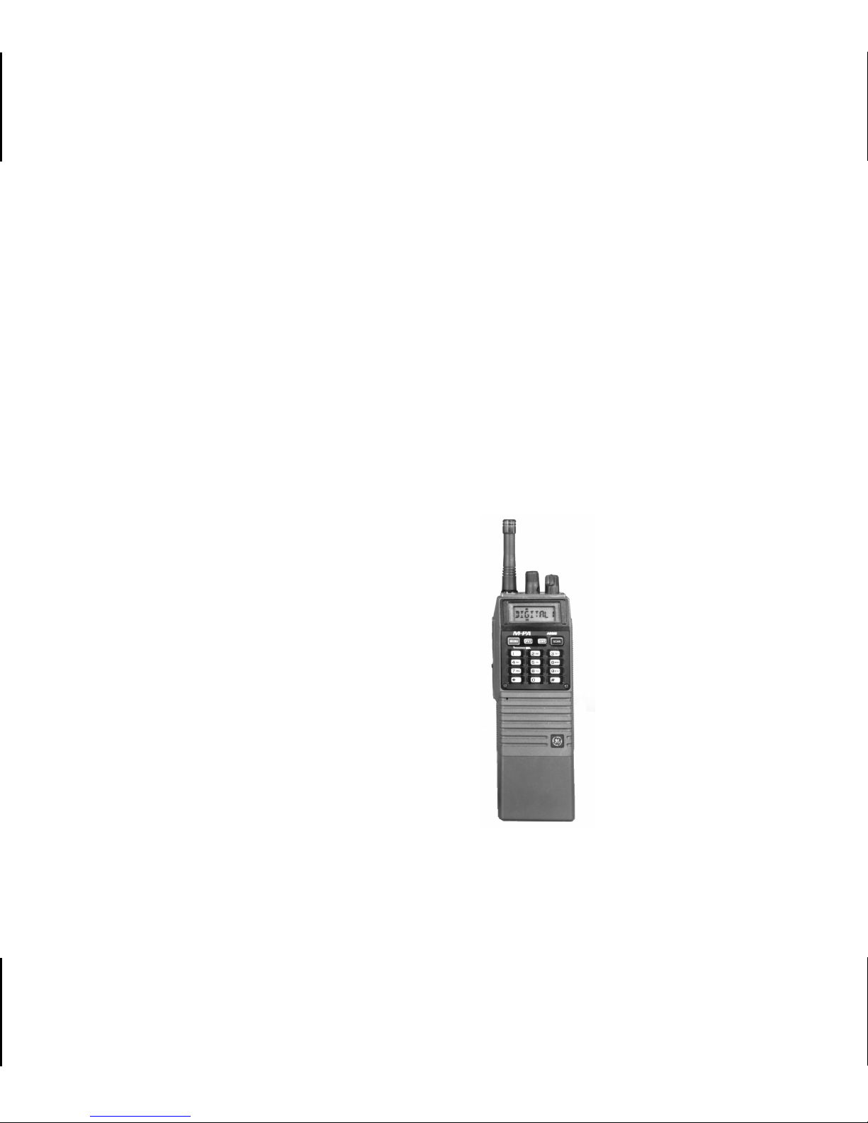
INTRODUCTION
The Aegis
M-PA Select, Scan and System
portable radios are high-performance two-wa y radios
that provide clear voice, Aegis digital, and Aegis
private communications. The Select, Scan and System radios are also compatible with Voice Guard
communication systems. Personality programming
allows maximum integration flexibility into a public
service radio system.
The radio must be equipped with the encrypt/decrypt option before operation in Aegis private or V oice
Guard modes is possible. This option allows the r adio
to communicate using highly secure state-of-the-art
Aegis and Voice Guard encryption and decryption
techniques.
Operating controls include a rotatable control
knob, rotatable volume control, push-to-talk, emergency and monitor buttons. In addition, the Scan
model includes an eight-button keypad while the
System model includes a 16-button keypad. The
on/off power switch for the unit is located on the
removable battery pack.
status of the radio. This backlit displa y also pro vides
twelve status flags (Scan and System) or eight status
flags (Select) that indicate various operating conditions such as private communications enab led, transmitter on, scanning, or emergency mode enabled.
®
The exact operation of your radio will vary depending upon the mode of operation, the radio’s
programming, and the particular radio system. Consult your radio system’s representative for particular
features that are programmed into your radio.
CONTROLS
ON/OFF SWITCH
The ON/OFF SWITCH is located on the battery
pack. Sliding this switch up will supply power to the
radio from the battery pack. An audible click will be
heard and the "ON" indicator will be exposed. When
the radio is turned on, it will perform a power-up self
test and then resume operation on the previous
operating channel as displayed in the LCD. Sliding
the switch down will turn the radio off.
The 8-digit alphanumeric liquid crystal display
(LCD) on the front of the radio displays the operating
3

VOLUME CONTROL KNOB
The VOLUME CONTROL KNOB is a rotatable
control on the top of the radio used to adjust the
receiver’s audio level in the speaker. Rotating this
knob in a clockwise direction will increase the audio
level. Counter-clockwise rotation will decrease the
audio lev el. Minimum levels m ay be programmed into
the radio to prevent missed calls due to too low of a
volume setting.
CONTROL KNOB
Select Model
NEL/CG SELECTION for details. A stop plate may
be installed under the knob to limit the maximum
number of positions to less than sixteen (16). It is
normally factory installed for fifteen (15) positions.
Some radios may be programmed with this knob
disabled.
PTT BUTTON
Pressing the PTT BUTTON on the side of the
radio will enable the radio’s transmitter. The "TX"
status flag in the display will turn on when the radio
is transmitting. Releasing the PTT BUTTON will return operation to receive mode.
The rotatable 16-position CONTROL KNOB located on the top of the radio selects the operating
channel. A stop plate may be installed under the
knob to limit the maximum number of positions to less
than sixteen (16). It is nor mally factory installed for
fifteen (15) positions.
Scan and System Models
The rotatable 16-position CONTROL KNOB located on the top of the radio is programmed to select
the operating channel, mode, or specific Channel
Guard encode/decode tones. See MODE/CHAN-
4
MONITOR BUTTON
The MONITOR BUTTON is used to unsquelch
the receiver. Momentarily pressing this button will
disable squelch and the receiver noise will be heard
in the speaker.
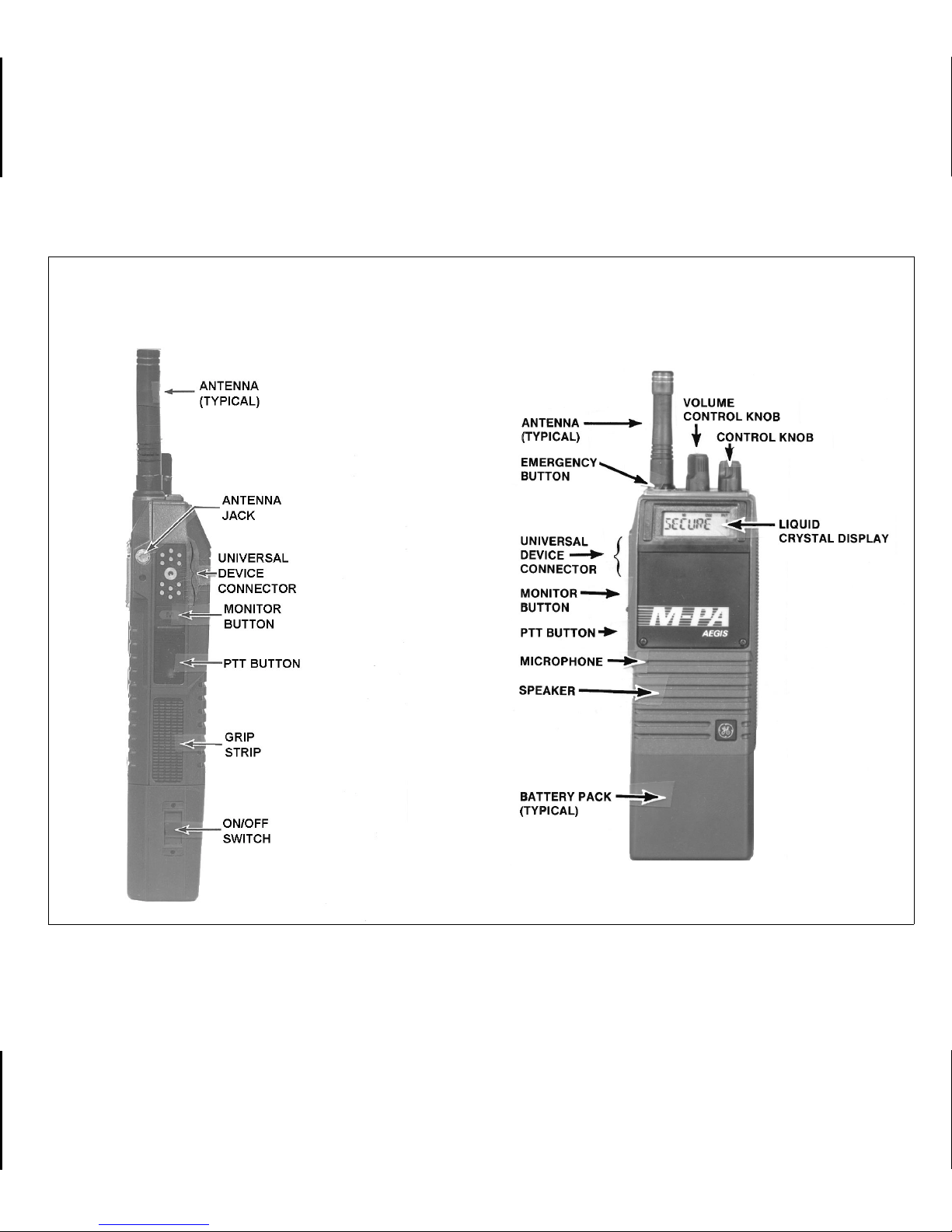
SIDE VIEW FRONT VIEW
Figure 1 - Aegis M-PA Select Model Radio
5
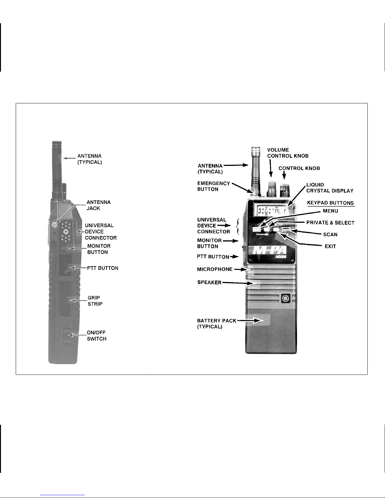
SIDE VIEW FRONT VIEW
Figure 2 - Aegis M-PA Scan Model Radio
6
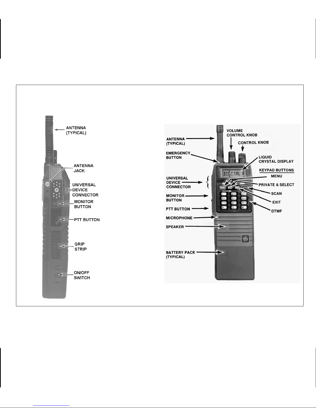
SIDE VIEW FRONT VIEW
Figure 3 - Aegis M-PA System Model Radio
7

If programmed enabled f or the selected channel,
Channel Guard (CG) and/or Type 99 (T99) signalling
will be enabled when the channel is selected. If CG
and/or T99 are enabled, the appropriate status flag
"CG" and/or "T99" will turn on. The MONITOR BUTTON may then be used to toggle CG and/or T99
between disabled and enab led by pressing and holding it for at least one (1) second; the appropriate
status flag will toggle on or off. The MONITOR B UTTON is also used to reset T99 operation after a call
is received.
EMERGENCY BUTTON
The EMERGENCY BUTTON is the small red
button located on top of the radio near the antenna.
If this button is programmed for emergency operation, pressing it for at least one (1) second will cause
the radio to transmit GE-STAR emergency signalling.
The "EMG" status flag will turn on. GE-STAR is
transmitted according to one of sev eral diff er ent programmable methods. See EMERGENCY OPERA-
TION for details.
MENU BUTTON (Scan and System Models)
Pressing the MENU button causes the radio to
scroll through up to seven (7) different menus programmed into the radio. After the desired menu is
displayed, the feature within the menu is selected
with the SEL button. The menus that may be programmed are:
Menu Display Function Or Use
"CHANNEL" The MENU and SEL buttons are
programmed for channel selection. When this display appears,
select the desired channel with
the SEL button and then press
EXIT.
"MODE" The MENU and SEL buttons are
programmed for mode selection.
When this display appears, select the desired mode by pressing the SEL button and then
press EXIT.
This button ma y also be programmed as an hom e
mode button. If programmed in this manner , pressing
it will switch operation to the programmed home
mode.
8
"PHONE" Allows selection of one (1) of the
ten (10) programmed or user entered telephone numbers for
automatic dialling.

"KEY LOCK" Allows the keypad buttons to be
locked or unlocked.
"SCAN A/D" Allows channels to be added to
or deleted from the scan list for
the current mode. The priorityone channel and the priority-two
channel are also set within this
menu.
"ALERT" Allows the alert tones to be dis-
abled or enabled.
"PHN EDIT" (System Model) Allows editing of
the telephone phone numbers
programmed into the radio.
PRIVATE BUTTON
The optional private transmit mode is enab led or
disabled by pressing and releasing the PVT button
(when the menu mode is not selected). When private
transmit mode is enabled, the "PVT " status flag in the
display will turn on. The radio is programmed for
switched or f orced priv ate operation. In the switched
configuration, the PVT button is operational. In the
forced configuration, the button is not operational.
If the radio is programmed for forced private
operation and the selected channel is programmed
for private operation, "FRCD PVT" will be displayed
when PVT is pressed; private transmit mode cannot
be disabled. If the radio is programmed for forced
private operation and the selected channel is not
programmed for private operation, "PVT DIS" will
momentarily show in the display when PVT is
pressed; the radio will not change to private mode. If
the encrypt/decr ypt option is not installed, the PVT
button has no function.
Figure 4 - M-PA Scan Model Keypad
9
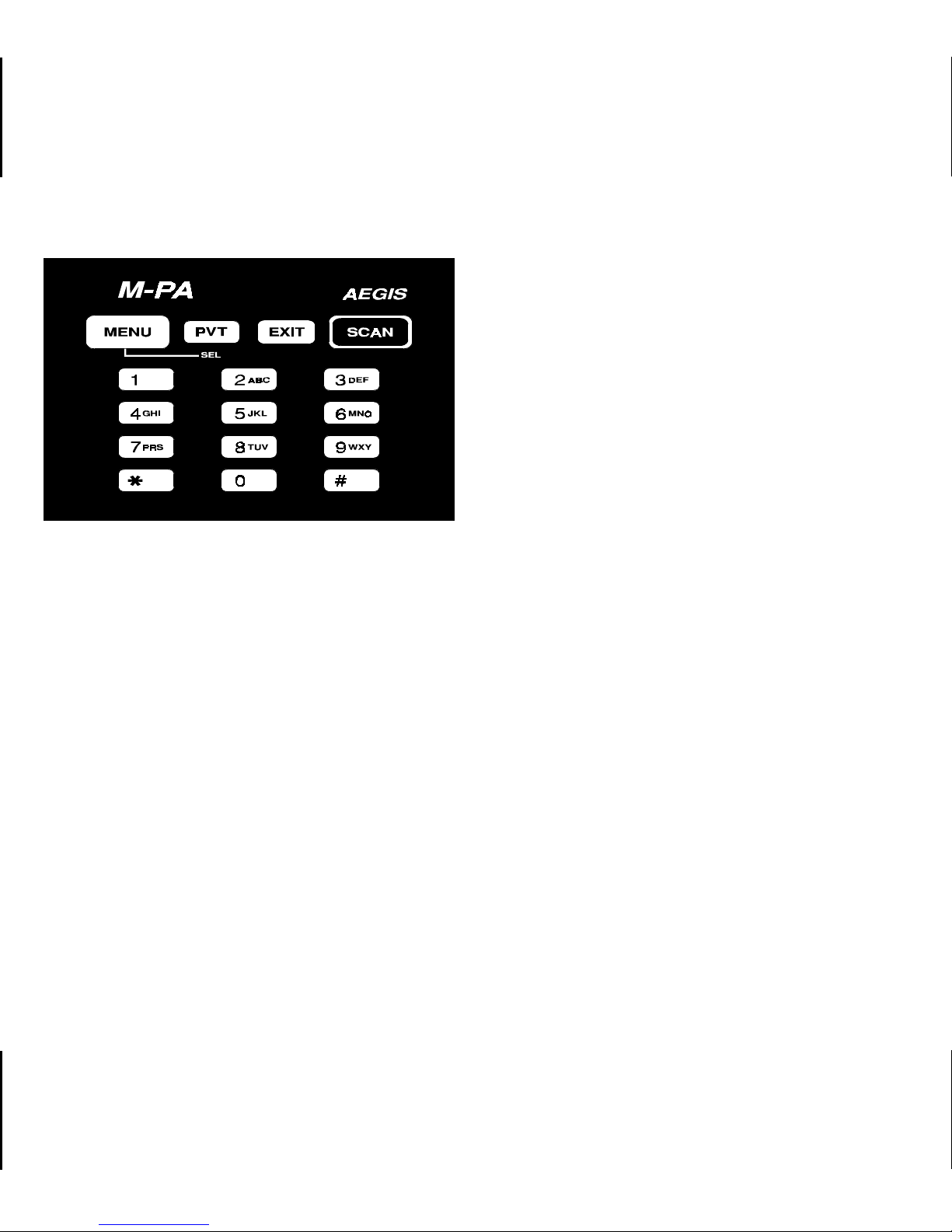
Figure 5 - Keypad
EXIT BUTTON
Pressing the EXIT button will cause the radio to
exit the current menu display and return operation to
the channel currently selected. If the menu mode is
not enabled when the button is pressed, pressing this
button will turn the display and keypad backlighting
on for thirty (30) seconds if the backlight is programmed on.
SCAN BUTTON
Pressing the SCAN button on the keypad will
toggle scan operation on and off. When the radio is
scanning, the "SCN" status flag in the display will
show and all channels on the scan list will be
scanned. See SCANNING CHANNELS for additional
details.
SELECT BUTTON
Selecting different features within each menu is
accomplished with the SEL button. First, the menu
mode must be enabled and the desired menu must
be chosen by pressing and releasing the MENU
button until the desired menu appears in the displa y.
After the menu is chosen, the desired function or
feature is selected by pressing the SEL button. For
example, to disable or enable the aler t tones, press
MENU until "ALERT" is displayed then press SEL to
select "ENABLED" or "DISABLED", as desired.
Next, press the EXIT button.
DTMF KEYPAD (System Model)
Telephone interconnect calls can be made using
the 12-button DTMF keypad. T his keypad is enabled
when a channel programmed for DTMF operation is
selected. See TELEPHONE INTERCONNECT
CALLS for details
10
INDICATORS
The LCD on the Select model has eight al-
phanumberic characters and eight status flags.
The LCD on the Scan and System models has
eight alphanumeric characters and twelve status
flags. This display indicates the current operating
channel and various other messages. Men u information is also display ed on the Scan and System Models
when enabled.
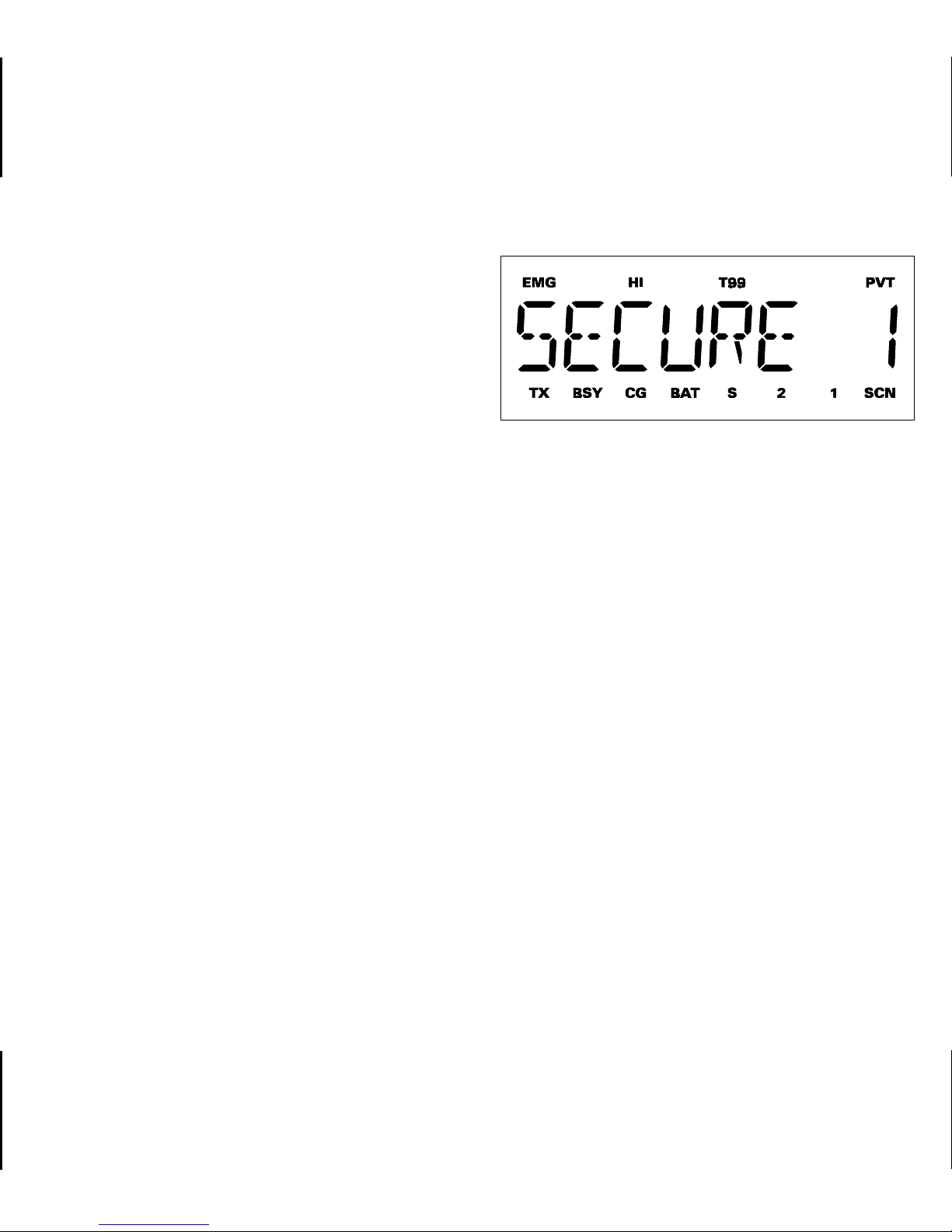
Figure 6 - Liquid Crystal Display
EMG EMerGency mode - On indicates emer-
gency GE-STAR signalling has been initiated by the user.
The System model also displays telephone interconnect numbers.
LCD backlighting will turn on for a short period
anytime an active b utton is pressed or the CONTROL
KNOB is rotated. Backlighting may be programmed
to remain off at all times.
On the Scan and System models pressing the
EXIT button when the menu mode is not enabled will
turn display and ke ypad backlighting on f or thirty (30)
seconds (if backlight programming is on).
The status flags located along the top and bottom of the display indicate operating status as follows:
HI HIgh power transmit - On indicates the
selected channel has been programmed
for high power transmit operation. Off
indicates low power transmit.
T99 Type 99 tone decode - On indicates T ype
99 tone decoding is enabled on the selected channel. Flashing indicates a T99
selective call has been received and the
radio must be reset to receive another
T99 call.
PVT PriVaTe mode - On indicates private
mode is enabled and the radio will transmit encrypted messages on the selected
channel. Flashing indicates an encrypted
message is being received.
11

TX Transmitter enabled - On when the radio
is transmitting.
BSY BuSY - On indicates a carrier is being
received (the channel is busy). Note that
if the selected channel is programmed for
Channel Guard (CG), Digital Channel
Guard (DCG), or Type 99 (T99) tone decode operation, the radio may not unsquelch if a valid tone(s) is not received;
the BSY status flag will be on.
CG Channel Guard - On indicates tone Chan-
nel Guard (CG) or Digital Channel Guard
(DCG) encode/decode is enabled on the
selected channel.
BAT BATtery low - On indicates the battery
pack’s charge is low.
NOTE
The remaining status flags are provided on the Scan and System models
only .
2 priority 2 - On indicates the selected chan-
nel is designated as the priority-two scan
channel.
SCN SCaN mode - On indicates the radio is
scanning.
UNIVERSAL DEVICE CONNECTOR
The Universal Device Connector (UDC) is located on the side of the radio just above the PTT and
MONITOR B UTT ONS. This connector provides connections for the e xternal accessories such as a headset, a speaker-mik e, or an emergency lany ard. When
the radio is locked in a v ehicular charger/repeater the
UDC provides the audio and control connections
between the radio and the vehicular charger/repeater. The UDC is also used by the maintenance
personnel when the radio is programmed.
ALERT TONES
S Scan list - On indicates the selected chan-
nel is on the scan list.
1 priority 1 - On indicates the selected chan-
nel is designated as the priority-one scan
channel.
12
The M-PA uses alert tones or "beeps" to indicate
various operating conditions. The alert tones may be
disabled when the radio is programmed. on the Scan
and System models, The alert tones may be enabled
or disabled via the menu mode if the "ALERT" f eature
is programmed. See "ALERT" MENU for details.
 Loading...