

Ericsson AEGIS FDMRTS M-PA NARROWBAND 9600, AEGIS EDACS M-PA Narrowband 9600 Operator's Manual
LBI-33054A
Operator’s Manual
AEGIS
FDMRTS M-PA
NARROWBAND 9600
PORTABLE RADIO
ericssonz

Table of Contents
Table of Contents (Cont.)
INTRODUCTION . . . . . . . . . . . . 5
CONTROLS . . . . . . . . . . . . . . 5
INDICATORS . . . . . . . . . . . . . 10
OPERATION . . . . . . . . . . . . . . 13
POWER-UP . . . . . . . . . . . . . 13
SYSTEM/GROUP/CHANNEL
SELECTION . . . . . . . . . . . . . 14
VOICE MODES . . . . . . . . . . . 15
Clear Modes . . . . . . . . . . . 15
NOTICE
This ma nu al covers Ericsson and General E l ectric prod ucts manufac t ured
and sold by Ericsson Inc.
NOTICE
The software contained in this device is copyrighted by Ericsson Inc.
Unpublis hed rights are res erved under the c opyright laws o f the United
States.
This manu al is published by Ericsson Inc., without any warranty.
Improvements and changes to this manual necessitated by typographical errors, inaccuracies of current information, or improvements to programs and/or equipment, may be made by Ericsson
Inc., at any time and with ou t no tice . Such cha ng es will b e incor po rtated into ne w editions o f this manua l. No part of this man ual may be
reproduced or transmitted in any form or by any means, electronic
or mechanical, including photocopying and recording, for any purpose, without the express written permission of Ericsson Inc.
Copyright © March 1995, Ericsson Inc.
Aegis Digital Mode . . . . . . . 16
Aegis Private And Voice Guar d
Private Modes . . . . . . . . . . 16
TRUNKED MODE OPERATION . . 20
Receiving A Message . . . . . . 20
Sending A Message . . . . . . . 21
Emergency Operation (Trunked
Mode) . . . . . . . . . . . . . . 23
Dynamic Regrouping . . . . . . 23
Wide Area System Scanning . . 24
Scanning Trunked Groups . . . 24
Special Calls . . . . . . . . . . 26
Manually Dialed Telephone Inter-
connect Calls . . . . . . . . . . . . 29
STATUS MESSAGE OPERATION . 30
CONVENTIONAL MODE
OPERATION . . . . . . . . . . . . 30
Receiving A Message . . . . . . 30
Sending A Message . . . . . . . 31
Emergency Operation (Conven-
tional Mode) . . . . . . . . . . . 33
Scanning Conventional
Channels . . . . . . . . . . . . 33
2

Table of Contents (Cont.)
OPERATING TIPS . . . . . . . . . . . 34
OPERA TING RULES AND REGULA-
TIONS . . . . . . . . . . . . . . . . . 35
BATTERY PACKS . . . . . . . . . . . 36
INSTALLING THE BATTERY PACK . 36
REMOVING THE BATTERY PACK . 36
CHARGING THE BATTERY PACK S38
RECHARGEABLE BATTERY PACK
DISPOSAL . . . . . . . . . . . . . . 38
SWIVEL MOUNT REMOVAL AND
REPLACEMENT . . . . . . . . . . . . 38
GLOSSARY . . . . . . . . . . . . . . 39
WARRANTY . . . . . . . . . . . . . . 44
NICKEL-CADMIUM BATTERY
WARRANTY . . . . . . . . . . . . . . 45
3
SCAN
SYSTEM
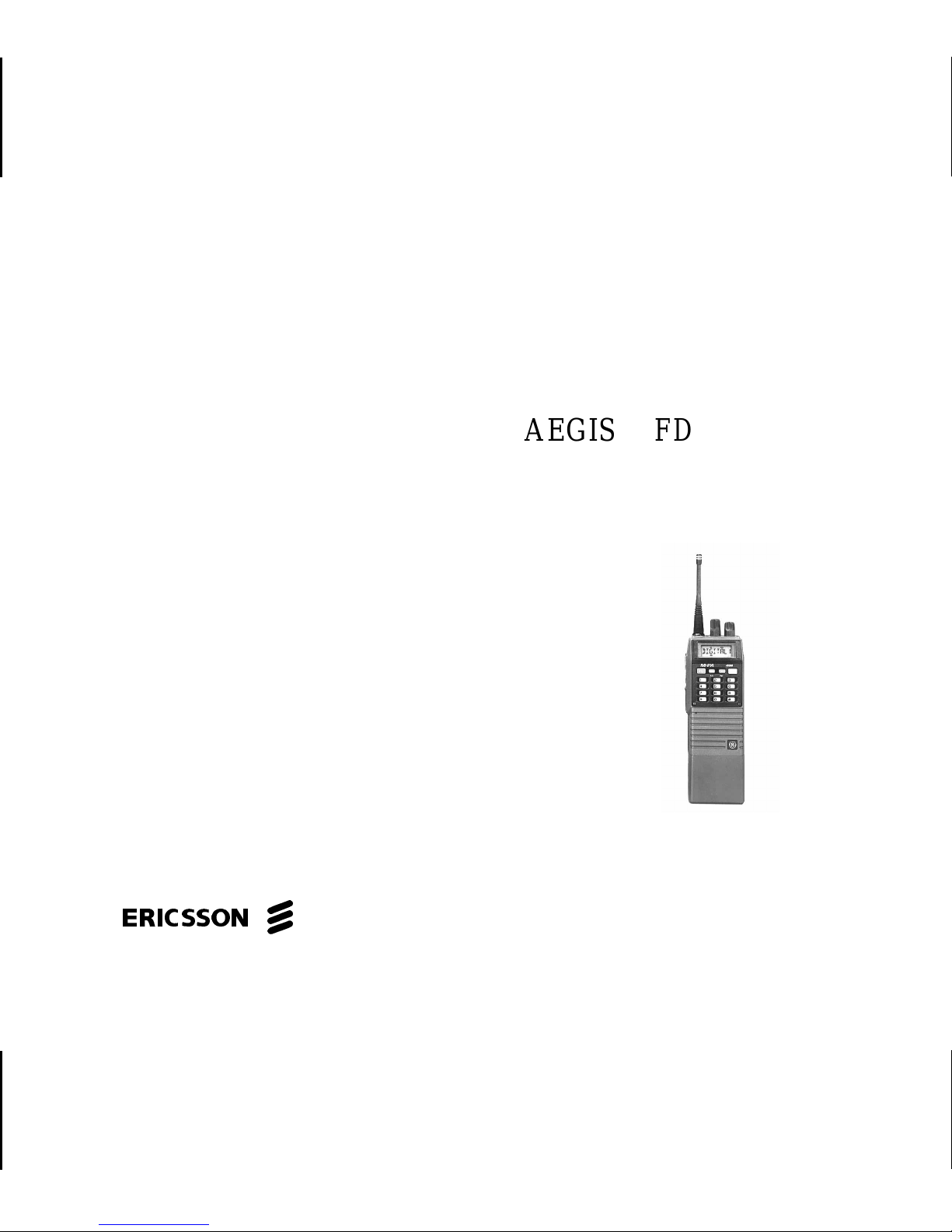
Figure 1 - Aegis EDACS Model Radio
4

INTRODUCTION
The Aegis M-P A System model portable radio
is a high-performance two-way radio that pr ovides
clear voice (for test only), Aegis digital, and Aegis
private communications. Personality programming allows maximum integration flexibility.
The radio must be equipped with the encrypt/decrypt option before operation in Aegis
private mode is possible. This option allows the
radio to communicate using highly secure stateof-the-art Aegis encryption and decryption technique.
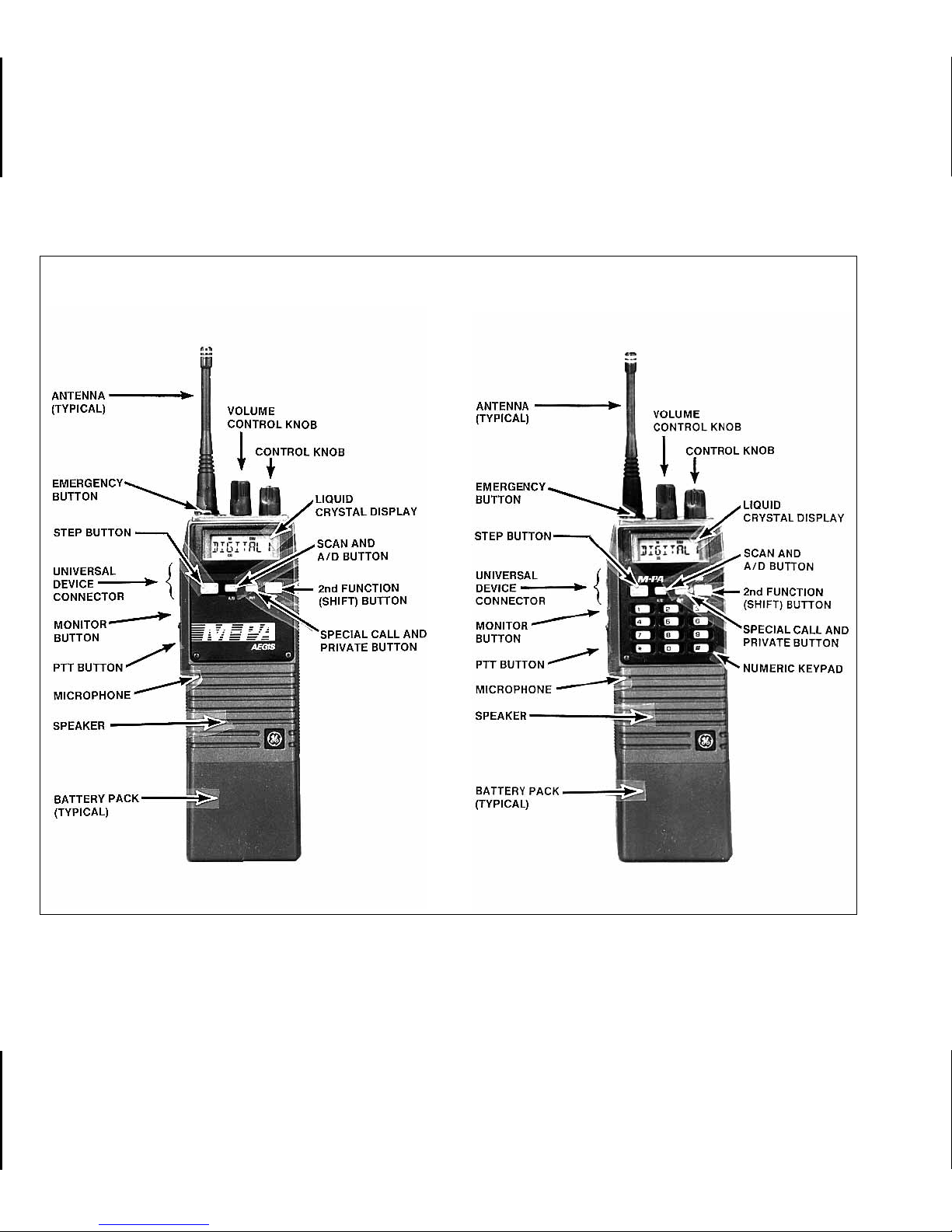
Operating controls on the radio include a
rotatable system/group/channel control knob, rotatable volume control, 16-button keypad (System
Model only), push-to-talk, emergency and monitor
buttons. The on/off power switch for the unit is
located on the removable battery pack.
The 8-digit alphanumeric liquid crystal display
(LCD) on the front of the radio displays the operating status of the radio. This backlit display also
has sixteen status flags that indicate various operating conditions such as private communica-
tions enabled, transmitter on, scanning, or emergency mode enabled.
The exact operation of your radio will vary
depending upon the mode of operation, the radio’s programming, and the particular radio system. Consult your radio system’s representative
for particular features that are programmed into
your radio.
CONTROLS
ON/OFF SWITCH
The ON/OFF SWITCH is located on the battery pack. Sliding this switch up will supply power
to the radio from the battery pack. An audible click
will be heard and the ON indicator will be exposed.
When the radio is turned on, it will perform a
power-up self test and then resume operation on
the previous operating system, group or channel
as displayed in the LCD. Sliding the switch down
will turn the radio off.
5

VOLUME CONTROL KNOB
PTT BUTTON
The VOLUME CONTROL KNOB is a rotatable control on the top of the radio used to
adjust the receiver’s audio level in the speaker.
Rotating this knob in a clockwise direction will
increase the audio level. Counter-clockwise rotation will decrease the audio level. Minimum levels
may be programmed into the radio to prevent
missed calls due to too low of a volume setting.
CONTROL KNOB
The rotatable 16-position CONTROL KNOB
located on the top of the radio may be programmed to select trunked groups and conventional channels or it may be progr ammed to select
systems. See SYSTEM/GROUP/CHANNEL SE-
LECTION for details.
A stop plate may be installed under the knob
to limit the maximum number of positions to less
than sixteen (16). It is normally factory installed
for fifteen (15) positions.
Pressing the PTT BUTTON on the side of the
radio will enable the radio’s transmitter. The TX
status flag in the display will turn on when the
radio is transmitting. Releasing the PTT BUTTON
will return operation to idle/receive mode.
When operating in a trunked system, the r adio
may be programmed to automatically transmit
(without the operator pressing the PTT BUTT ON)
to maintain communication with the site controller .
The TX status flag will turn on when the radio is
transmitting.
MONITOR BUTTON
Trunked Mode
When operating in trunked mode, pressing
the MONITOR BUTTON after an individual call
has been received will return the radio to the
group call mode. The radio will not respond on an
individual basis, but will then transmit group calls
when the PTT BUTTON is pressed. The r adio will
also automatically return to the group call mode
after the programmed call-back time-out period
expires.
6
Pressing the MONITOR BUTTON will also
clear any digits entered from the num eric keypad
and return the radio to the selected group display .
In addition, this button is used to toggle between group and regroup settings if the Dynamic
Regrouping mode (with deselect capability) has
been enabled by the site controller.
Conventional Mode
When the radio is operating in conventional
mode the MONITOR BUTTON is used to unsquelch the receiver.
EMERGENCY BUTTON
When operating in trunked mode, pressing
and holding the red EMERGENCY BUTTON on
top of the radio for a programmable time period
will initiate an emergency call with voice operation
on the programmed home group. If no home
group is programmed into the r adio, voice operation will be on the selected group.
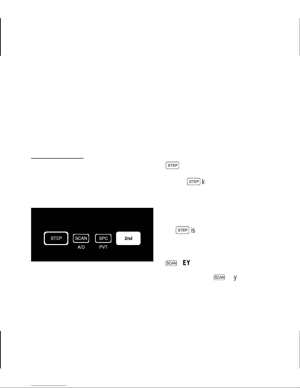
KEY
S
The
S
key located on the keypad may be
programmed to select trunked groups and conventional channels or it may be programmed to
select systems. See SYSTEM/GROUP/CHAN-
NEL SELECTION for details.
Figure 2 - Scan Keypad
S
is also used to scroll through the programmed special call table when the special call
mode is enabled.
s
KEY
Pressing the
s
key on the keypad will
toggle scan operation on and off (for radios which
have this feature). When the radio is scanning,
the SCN status flag in the display will show and
7
all groups in the scan list in the current system will
be scanned.
While in special call mode, the next programmed special call may be selected by pressing
S
. Pressing
@
then
S
will select the
previous programmed special call.
The caller’s ID of the last received individual
call is selectable by pressing the special call
key. See
Special Calls for details.
P
2nd FUNCTION KEY
On the Scan Model, two(2) of the keys on the
keypad are dual-function keys. Press and release the blue function key to shift keypad selection to the A/D and PVT keys.
Figure 3 - System Keypad
SPECIAL CALL KEY
When operating in trunked mode, pressing
P
will switch operation from the group select
mode to the special call mode. The last selected
special call will be displayed.
8
Seven (7) of the keys on the System model
keypad are dual-function keys. Press and release the blue
@
function key to shift keypad
selection to the A/D, PVT, STO, RCL, CLR, KEY
or STS keys. The following paragraphs describe
operation of the shifted buttons.
ADD/DELETE KEY (Shifted SCAN Key)
When in trunked mode, pressing and releas-
ing
@
and then pressing A/D (shifted
s
key)
will add the selected group to the scan list if it is
not already on the list. Repeating this sequence
will delete the group from the list. When the
selected group is on the scan list, the S status flag
will show in the display.
NOTE
Do not use in Conventional mode.
disabled. If the selected group or channel is not
programmed for private operation, PVT DIS will
momentarily show in the display when
@
PVT
is pressed; the radio will not change to private
mode. See PRIVATE COMMUNICATIONS for
additional details.
STORE KEY(Shifted)
1
(shifted digit 1) allows ten (10) telephone numbers and ten (10) radio ID numbers to
be stored and later recalled with the RCL button.
Scan must be turned off befor e groups can be
added to or deleted from the scan list. See
s
s
KEY for details.
PRIVATE BUTTON (Shifted SPC Key)
Private transmit mode is enabled or disabled
by pressing and releasing
PVT (shifted
P
key). When enabled, the PVT
@
and then pressing
status flag in the display will turn on.
If the radio is programmed for forced private
operation, FRCD PVT will be displayed when
@
PVT is pressed; private transmit mode is not
Store a telephone number by entering the
number (up to 29 digits) followed by an asterisk
(*). Next, enter the storage location (1-10) and
press and release
@
and then press
1
STORED will be displayed for two seconds.
Store individual radio ID numbers by enter ing
the ID number (1 - 16382) followed by a pound
sign (#). Next enter the storage location (1-10)
and press and release
@
and then press
1
STORE D will be displayed for two seconds.
.
.
9
RECALL KEY (Shifted Digit 3)
3
allows the previously stored telephone
or radio ID numbers to be recalled. To recall a
number first enter an * or # (* for telephone
number, # for radio ID number) and then enter
the storage location (1-10). Next press and release
@
and then press
3
and the number
will be displayed.
CLEAR KEY (Shifted # )
To clear the last digit entered, press and
release
@
and then press
#
(shifted #
button). Holding CLR down will repetitively clear
previous digits. The radio will return to the last
operating state when all entered digits are
cleared.
KEY KEY (Shifted)
Pressing and releasing
ing
^
will display the current operating crypto-
@
and then press-
graphic number. See PRIVATE COMMUNICA-
TIONS for details.
STATUS KEY
The
5
key is not currently used.
KEYPAD LOCK FEATURE
To prevent accidental activation of the keys
on the keypad, press and release the
@
function key followed by pressing the MONITOR button to lock the keypad; LOCKED will be displayed
momentarily. To unlock the keypad, press and
release the
@
function key followed by press-
ing the MONITOR button a second time; UN-
LOCKED will be displayed momentarily.
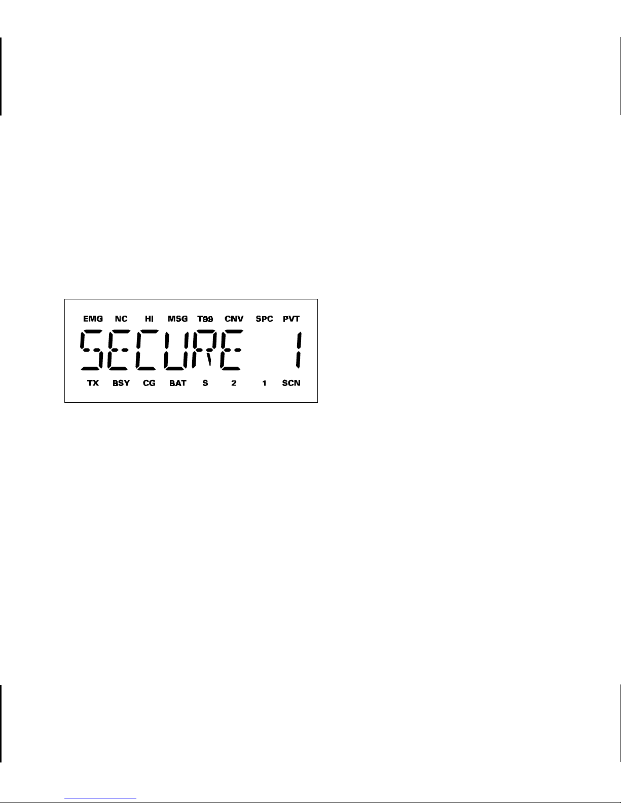
INDICATORS
The radio’s liquid crystal display (LCD) located on the front panel has eight (8) alphanumeric characters and sixteen (16) status flags.
This display provides indications of the current
operating system, group or channel and it displays various other messages such as special call
ID names or numbers, and telephone interconnect numbers.
10
LCD backlighting will turn on for 2 seconds
anytime an active key or button is pressed or the
CONTROL KNOB is rotated. Backlighting may be
programmed to remain off at all times.
The sixteen (16) status flags located along
the top and bottom of the display indicate operating modes and conditions as follows:
Figure 4 - Liquid Crystal Display
EMG EMerGency mode - On indicates an
emergency call has been initiated by
the user. Flashing indicates an emergency call has been received.
NC No Control channel - On indicates the
radio is not receiving the trunked control channel. Flashing indicates the
trunked system is in a failsoft condition
(supervisory radios only).
HI HIgh power transmit - On indicates
the selected system or channel has
been programmed for high power
transmit operation. Off indicates low
power transmit.
MSG MeSsaGe - Flashing indicates an in-
dividual call has been received
(trunked mode).
CNV CoNVentional mode - On indicates the
radio is operating in the conventional
mode.
SPC SPecial Call mode - On indicates the
special call mode has been enabled
(trunked mode).
PVT PriVaTe mode - On indicates private
mode is enabled and the radio will
transmit encrypted messages on the
selected group or channel. Flashing
indicates an encrypted message is being received.
TX Transmitter enabled - On when the
radio is transmitting.
BSY BuSY - When in trunked mode, on
indicates the radio is receiving a call;
flashing indicates a call has been
queued. In conventional mode, on indicates a carrier is being received.
11

BAT BATtery low - On indicates the battery
pack’s charge is low.
S Scan list - On indicates the selected
group/channel is on the scan list.
SCN SCaN mode - On indicates the radio is
scanning (for radios which have this
feature).
UNIVERSAL DEVICE CONNECTOR
The Universal Device Connector (UDC) is
located on the side of the radio just above the PTT
and MONITOR BUTTONS. This connector provides connections for the external accessories
such as a headset, a speaker-mike, or an emergency lanyard. When the radio is locked in a
vehicular charger/repeater the UDC provides the
audio and control connections between the radio
and the vehicular charger/repeater. The UDC is
also used by the maintenance personnel when
the radio is programmed.
NOTE
Anytime there is a device change to the
UDC, the radio should be turned off and
then back on again.
ALERT TONES
The radio so unds five (5) bas ic al ert tone s or
"beeps" to indicate various operating conditions.
Alert tones may be programmed to remain off at
all times.
•
500 Hz Tone
–
trunked failure tone sounds when a trunked
failure has occurred (call
denied, failed confirmation).
–
low battery - sounds when
the battery pack’s charge
is low.
•
800 Hz Tone
–
private mode disabled on a conventional channel, sounds when the PTT
BUTTON is pressed if private transmit mode has
previously been disabled.
•
1000 Hz Tone
–
alert tone - sounds when
a button is pressed and a
status change occurs
–
channel access tone sounds when a trunked
channel has been assigned and it is clear to
talk.
12

•
1200 Hz Tone
–
private mode channel access tone - sounds when
the radio is in the private
transmit mode, a trunked
channel has been assigned and it is clear to
talk.
example, the radio is out of range of the previous
trunking site. It may be necessary move to another location, select another trunking system, or
a conventional channel.
SYSTEM/GROUP/CHANNEL SELECTION
•
2500 Hz Tone
–
call queued tone - sounds
when a trunked call is
queued.
OPERATION
POWER-UP
After the battery pack and antenna have been
installed, turn the radio on by sliding the ON/OFF
SWITCH on the battery pack up. After the radio
has completed a power-up self-test, it will begin
operation on the last operating state as displayed
in the LCD. If programmed on, the power-up alert
tone (beep) will be heard.
If the radio was previously operating in a
trunking system and communication with this system’s control channel cannot be established, the
NC status flag will turn on. This may occur if, for
The radio may be programmed with one of
two different system/group/ channel selection
modes as follows:
•
Systems are selected with the
S
key;
groups and channels are selected with the
CONTROL KNOB.
or
•
Systems are selected with the CONTROL
KNOB; groups and channels are selected
with the
S
key.
13
STEP Key Programmed For System
Selection
CONTROL KNOB Programmed For
Group/Channel Selection
CONTROL KNOB Programmed For System
Selection
STEP Key Programmed For Group/Channel
Selection
System Selection
Press and release
S
to select the next
system programmed into the radio as indicated in
the display. To select the previous system, pr ess
and release
down
S
@
and then press
S
. Holding
will cause the radio to automatically
scroll through the system list.
Upon reaching an end of the system list, the
radio may be programmed to stop selection or
wrap around (go from one end to the other).
Group/Channel Selection
After the desired system is selected with the
S
key, rotate the CONTROL KNOB to the
desired trunked group or conventional channel as
indicated in the display. A stop-plate may be
placed under the knob which will limit the maximum positions to less than sixteen (16).
System Selection
Rotate the CONTROL KNOB to the desired
system as indicated in the display. A stop-plate
may be placed under the knob which will limit the
maximum positions to less than sixteen (16).
Group/Channel Selection
After the desired system is selected with the
CONTROL KNOB, press and release
S
to
select the next trunked group or conventional
channel programmed into the radio as indicated
in the display. To select the previous group or
channel, press and release
S
. Holding down
S
@
and then press
will cause the radio to
automatically scroll through the group/channel
list.
Upon reaching an end of the group/channel
list, the radio may be programmed to stop selection or wrap around (go from one end to the other).
14
 Loading...