

Ericsson AEGIS FDMRTS M-PA Maintenance Manual
Maintenance Manual
LBI-33056A
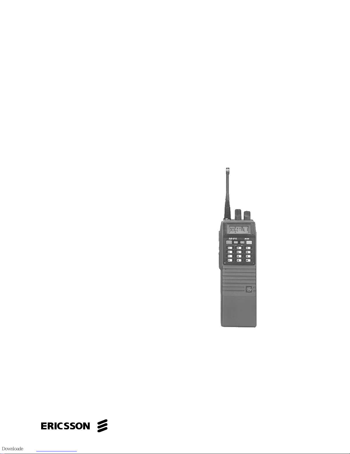
AEGISTM FDMRTS M-PA
UHF PORTABLE RADIO
TM
ericssonz
TABLE OF CONTENTS
Rear Cover Assembly . . . . . . . . . . . . . . . . . . . . . . LBI-38383
Front Cove r Assembly (Later) . . . . . . . . . . . . . . . . . . LBI-38834
Control Boa rd . . . . . . . . . . . . . . . . . . . . . . . . . . LBI-39157
Service Section . . . . . . . . . . . . . . . . . . . . . . . . . . LBI-33 057

LBI-33056
TABLE OF CONTENTS
SPECIFICATIONS . . . . . . . . . . . . . . . . . . . . . . . . . . . . . . . . . . . . . . . . . . . . . . . . . . 3
INTRODUCTION . . . . . . . . . . . . . . . . . . . . . . . . . . . . . . . . . . . . . . . . . . . . . . . . . . 5
Trunked Features . . . . . . . . . . . . . . . . . . . . . . . . . . . . . . . . . . . . . . . . . . . . . . . . 5
Conventional Features . . . . . . . . . . . . . . . . . . . . . . . . . . . . . . . . . . . . . . . . . . . . . . 6
General Features . . . . . . . . . . . . . . . . . . . . . . . . . . . . . . . . . . . . . . . . . . . . . . . . . 6
DESCRIPTION . . . . . . . . . . . . . . . . . . . . . . . . . . . . . . . . . . . . . . . . . . . . . . . . . . . . 7
Rear Cover Assembly . . . . . . . . . . . . . . . . . . . . . . . . . . . . . . . . . . . . . . . . . . . . . . 7
Front Cover Assembly . . . . . . . . . . . . . . . . . . . . . . . . . . . . . . . . . . . . . . . . . . . . . . 7
Antennas . . . . . . . . . . . . . . . . . . . . . . . . . . . . . . . . . . . . . . . . . . . . . . . . . . . . . 7
Battery Packs . . . . . . . . . . . . . . . . . . . . . . . . . . . . . . . . . . . . . . . . . . . . . . . . . . 10
Universal Device Connector . . . . . . . . . . . . . . . . . . . . . . . . . . . . . . . . . . . . . . . . . . 10
PROGRAMMING . . . . . . . . . . . . . . . . . . . . . . . . . . . . . . . . . . . . . . . . . . . . . . . . . . 11
OPERATOR MANUALS . . . . . . . . . . . . . . . . . . . . . . . . . . . . . . . . . . . . . . . . . . . . . . . 12
OPERATING TIPS . . . . . . . . . . . . . . . . . . . . . . . . . . . . . . . . . . . . . . . . . . . . . . . . . . 12
INTRINSICALLY SAFE USAGE . . . . . . . . . . . . . . . . . . . . . . . . . . . . . . . . . . . . . . . . . . 12
Battery Packs . . . . . . . . . . . . . . . . . . . . . . . . . . . . . . . . . . . . . . . . . . . . . . . . . . 12
Accessories . . . . . . . . . . . . . . . . . . . . . . . . . . . . . . . . . . . . . . . . . . . . . . . . . . . 12
MAINTENANCE . . . . . . . . . . . . . . . . . . . . . . . . . . . . . . . . . . . . . . . . . . . . . . . . . . . 13
Preventive Maintenance . . . . . . . . . . . . . . . . . . . . . . . . . . . . . . . . . . . . . . . . . . . . . 13
ILLUSTRATIONS
Figure 1 - Syste m Model . . . . . . . . . . . . . . . . . . . . . . . . . . . . . . . . . . . . . . . . . . . . 8
Figure 2 - Scan Model . . . . . . . . . . . . . . . . . . . . . . . . . . . . . . . . . . . . . . . . . . . . . . 8
Figure 3 - Select Model . . . . . . . . . . . . . . . . . . . . . . . . . . . . . . . . . . . . . . . . . . . . . 8
Figure 4 - Side View (All Mo dels) . . . . . . . . . . . . . . . . . . . . . . . . . . . . . . . . . . . . . . . 8
Figure 5 - Options And Ac c essories . . . . . . . . . . . . . . . . . . . . . . . . . . . . . . . . . . . . . . . 9
Figure 6 - UDC Pin-Out . . . . . . . . . . . . . . . . . . . . . . . . . . . . . . . . . . . . . . . . . . . . . 11
Table 1 - UHF Antennas . . . . . . . . . . . . . . . . . . . . . . . . . . . . . . . . . . . . . . . . . . . . . 10
Table 2 - UDC Pin Fu nctions . . . . . . . . . . . . . . . . . . . . . . . . . . . . . . . . . . . . . . . . . . 11
T a ble 3 - Operator Manuals . . . . . . . . . . . . . . . . . . . . . . . . . . . . . . . . . . . . . . . . . . . 12
Page
This manual cove rs Eri c sson and Gene ra l Elect ric pro duc ts m an ufa ctured and sold by Eri csson In c.
Repairs to this equipment should be made only by an authorized service technician or facility designated by the supplier.
Any repairs, alterations or substitution of recommended parts made by the user to this equipment not approved by the
manufac tu re r could void the user’ s authority to operate the eq uip ment in addi ti on t o the man ufa c tur er’s warran ty.
The software contained in this device is copyrighted by Ericsson Inc. Unpublished rights are reserved under the copyright
laws of the Unit ed Sta te s.
This manual is published by Ericsson Inc., without any warranty. Improvements and changes to this manual necessitated by typographical errors, inaccuracies of current information, or improvements to programs and/or equipment, may be made by Ericsson Inc., at any time and without notice. Such changes will be incorporated into new editions of this
manual. No part of this manual may be reproduced or transmitted in any form or by any means, electronic or mechanical, including photocopying and recording, for any purpose,
without the express written permission of Ericsson Inc.
Copyright ©April 1995, Ericsson Inc.
2
NOTICE!
NOTE
NOTICE!

SPECIFICATIONS*
GENERAL
Frequency Ra ng e 485-505 MHz
Frequenc y St ab il it y 2.5 ppm
Channel Spacing 12.5 kHz
Operating Temperature Range -20°C to +55°C
Maxim um Relative Humidity 90% at 55 °C
Batte ry Voltag e 7.5 Vdc ( nominal)
Dimensions (H x W x D)
less battery, knobs and antenna 140 x 69 x 38 mm (5.52 x 2.72 x 1.50")
with High Cap. Battery 197 x 69 x 38 mm (7.77 x 2.72 x 1.50")
Weight
less battery 567 grams (20.0 ounces)
with High Cap. Battery 815 grams (28.7 ounces)
LBI-33056
TRANSMITTER
High/Low RF Power Out put 3 W a tts / 1 Watt (progra m m ab le on a per syst em or chan nel
basis)
Maximum Fre que ncy Separa ti on 20 MHz (no degradatio n)
FM Deviation ±2.5 kHz
FM Hum and Noise -40dB (companion receiver)
Spurious and Ha rmonic Emissio n s -65 dBc
Audio Response +1 to -3dB (6 dB/octave pre-emphasis from 300 Hz to 3 kHz)
Audio Distortion less than 3% (at 1000 Hz tone, 3 kHz devi atio n)
RECEIVER
Sensitivity (12 dB SINAD) -116 dBm (0.3 5 mV)
Maximum Fre que ncy Separa ti on 20 MHz (no degradatio n)
Selectivity at 12.5 kHz
485 - 505 MHz -60 dB
3

LBI-33056
SPECIFICATIONS* (Continued)
Critical Squelch 10 dB SINA D
Intermodulation
485 - 505 MHz -70 dB
Spurious and Image Rejection -75 dB
Audio Output 500 mW (24-ohm load impedance)
Audio Response +2 to -8 dB (6 dB/octave de -em pha sis from 300 Hz to 3 kHz)
Audio Distortion less than 5% (at 500 mW )
AEGIS SYSTEM
Voice Modes digital and pri va te (must be equipped with an en cr ypt /dec ryp t
option to operate in private mode), clear mode can also be
programme d for test pur pose s.
Vocoding Method adapti ve mu lt iba nd enc od ing (sub-band cod ing in Voice Guar d
mode)
Outside Addre ssing 144 available
Digital Signal ling continuous in digita l or priv ate mode
Data Rate 9600 baud
Digital/Priva te Mode Pe rfo rman ce assured acquisition at 12 dB SINAD (SINAD measured in
clea r mo de)
Automatic Receive Operation automatically switches to the correct mode based on the
presence of digital sync
CRYPT O G RAP HIC (OP TIONAL)
Encrypt io n Technique
non-linear prod uc t/blo ck transfor ma tion
Key Permutations
1.8 x 10
Key Storage
EEPROM (permanent unless overwritten)
Key Storage Loca tion
EEPROM loca ted on Contr ol Bo ard
* These specifications ar e inte nd ed prima ri ly for the use of the service m an. See the appr opri a te Spec ific atio ns Shee t for th e
comp lete s peci f ication s.
19
(effectively 3.4 x 1038 with CUE codes)
4

LBI-33056
INTRODUCTION
The Aegis FDMR TS M-PA radio is a high quality m icro processor controlled synthesized portable two-way FM radio. The unit complements the Aegis FDMRTS trunked
system by providing a small, rugged, easy to operate and
easy to program portable radio for the UHF trunking environment. The radio also provides conventional communications in the UHF spectrum. M-PA operation is highlighted
by its programming versatility. This allows tailored operation of the portable radio to meet the needs of the radio system and the individual users. The Aegis FDMRTS M-PA
radio meets or exceeds all of th e APCO 16 portable radio
equipment requirements for digitally trunked and conventional commu nicati ons.
Aegis digital signals provide improved weak signal performance and impedance to unauthorized monitoring. Radios equipped with an encrypt/decrypt option offer very
secure communic ati ons when op erating in pr iva t e mode . MPA radios equipped with an encrypt/decrypt option can operate in two (2) diffe rent voic e modes. The voic e mo de s ar e:
Aegis digital and private. A radio not equipped with an encrypt/decrypt option can operate only in digital mode. A
clear voice (Analog) mode can also be programmed for test
purposes.
An Aegis FDMRTS M-PA radio’s voice mode is programmed on a per group basis. For example, if the radio is
equipped with an encrypt/de crypt option e ach trunked group
can be programmed for either private mode or Aegis digital
mode operation and the radio operates in the programmed
mode when the gro up is sele cte d.
Three (3) differe nt M- PA radio models are availa ble: Select, Scan and System.
The M-PA Select model radio is the basic version that
can be programmed with up to sixteen (16) independent
trunked groups and/or conventional channels. This unit features an eight-digit alphanumeric liquid crystal display
(LCD) and a 16-position knob for group/channel selection.
The display is backlit for nighttime and low-level ambient
light ope ration.
Scan and System model radios have an LCD similar to
the Select model radio. A keypa d is added to these radios (4button on Scan model, 16-button on System model) to provide additional features not available on the Select model
radio. These radios can be programmed with up to fifty (50)
systems with sixteen (16) groups in each, or sixteen (16)
systems with fifty (50) groups in each. In addition, up to
forty-eight (48) conventional channels and ninety-nine (99)
special calls can be programmed. Special calls include individual and telephone interconnec t call s. A Syste m mo de l ra -
dio also allows storage of ten (10) operator-entered telephone numbers and ten (10) radio ID numbers. These numbers can be recalled at will and initiated. Manually dialled
telephone interconnect calls and conventional mode DTMF
dialing is also provided by the System model’s 16-button
keypad. Both the Scan and System model radios provide
scan capability.
TRUNKED FEATURES
• Programmable Multiple System Capability - The
radio can operate on different trunked sites or on
different systems on the same site. Scan and System
model radios can be programmed with a maximum of
fifty (50) systems with a maximum of sixteen (16)
groups in each system. A Select model radio can be
programmed wit h a maxi mu m of sixtee n (16 ) syste ms
with one group in eac h.
• Programmable Multiple Group Capability - The
radio can communicate with many groups within a
system. Scan and System model radios can be
programmed with a maxim um of fifty (50) groups per
system. If the Control Knob is programmed for group
selection, up to sixteen (16) groups can be selected
and system selection (50 maximum) is accomplished
with the STEP button on the keypad. If the Control
Knob is programmed for system selection, up to
sixteen (16) systems can be selected and then up to
fifty (50) groups can be selected via the STEP button.
In a Select model radio, a maximum of sixteen (16)
groups (from one or more systems) can be programmed and selec t ed with the Control Knob.
• P rogrammable Group Call Capability - The radio
can simultaneously call all units within a group.
• Special Call Mode - Scan and System model radios
can initiate special calls. These calls include
individual and telephone interconnect calls. Up to
ninety-nine (99) special calls can be programmed into
the radio. Special calls cannot be programmed into a
Select model radio; therefore, these radios cannot
initiate special calls.
• Remote Dynamic Regrouping Capability - The
dispatch center can regroup radios for multi-agency
communications.
• Remote Disable - If lost or stolen, the radio can be
remotely disabl ed by the System Ma nage r.
5
 Loading...