

Ericsson AEGIS EDACS M-PA Operator's Manual
Operator’s Manual
AEGISTM EDACS
®
M-PA
SCAN MODEL
PORTABLE RADIO
LBI-38794C
TM
E

TABLE OF CONTENTS
TABLE OF CONTENTS (CONT.)
INTRODUCTION . . . . . . . . . . . . . . . 5
CONTROLS . . . . . . . . . . . . . . . . . 5
INDICATORS . . . . . . . . . . . . . . . . . 9
UNIVERSAL DEVICE CONNECTOR . . . 11
ALERT TONES . . . . . . . . . . . . . . . 11
OPERATION . . . . . . . . . . . . . . . . 12
POWER-UP . . . . . . . . . . . . . . . . . 12
SYSTEM/GROUP/CHANNEL
SELECTION . . . . . . . . . . . . . . . . . 12
VOICE MODES . . . . . . . . . . . . . . . 13
Clear Modes . . . . . . . . . . . . . . 13
Aegis Digital Mode . . . . . . . . . . . 14
Aegis Private And Voice
Guard Private Modes . . . . . . . . . . 14
TRUNKED MODE OPERATION . . . . . . 17
Receiving A Message . . . . . . . . . 17
Sending A Message . . . . . . . . . . 19
Emergency Operation . . . . . . . . . 20
Dynamic Regrouping . . . . . . . . . . 20
Wide Area System Scanning . . . . . . 21
This manual is published by
and chang es to this manual necessitat ed by typo graphical er rors, inaccur acies of curr ent
information, or improvements to programs and/or equipment, may be made by
, at any time a nd w it ho ut notice. Su ch cha ng es w ill be incorportated into new editions
Inc.
of this manual. No part of this manual may be reproduced or transmitted in any form or by
any means, electronic or mechanical, including photocopying and recording, for any
purpose, without the express written permission of
Copyright © May, 1992, Ericsson GE Mobile Communications Inc.
Ericsson Inc.
, without any warranty. Improvements
Ericsson
Ericsson Inc.
Scanning Trunked Groups . . . . . . . 21
Special Calls . . . . . . . . . . . . . . 22
CONVENTIONAL MODE
OPERATION . . . . . . . . . . . . . . . . . 24
Receiving A Message . . . . . . . . . . 24
Sending A Message . . . . . . . . . . 25
Emergency Operation . . . . . . . . . 27
Scanning Conventional Channels . . . 27
OPERATING TIPS . . . . . . . . . . . . . . 28
OPERATING RULES AND
REGULATIONS . . . . . . . . . . . . . . . 29
BATTERY PACKS . . . . . . . . . . . . . . 30
INSTALLING THE BATTERY PACK . . . . . 30
REMOVING THE BATTERY PACK . . . . . 30
CHARGING THE BATTERY PACKS . . . . . 31
RECHARGEABLE BATTERY PACK
DISPOSAL . . . . . . . . . . . . . . . 32
SWIVEL MOUNT REMOVAL
AND REPLACEMENT . . . . . . . . . . . . 32
INTRINSICALLY SAFE USAGE . . . . . . . 33
BATTERY PACKS . . . . . . . . . . . . 33
ACCESSORIES . . . . . . . . . . . . . 33
GLOSSARY . . . . . . . . . . . . . . . . . 35
WARRANTY . . . . . . . . . . . . . . . . . 38
NICKEL-CADMIUM BATTERY
WARRANTY . . . . . . . . . . . . . . . . . 39
2

PRODUCT SPECIFICATION FOR CE MARKED
EQUIPMENT
The M-PA Portable conforms to the following
Product Specifications.
EUROPEAN STANDARDS:
Safety: Not Applicable
EMC: prETS 300 279 (August 1995)
TTD: Not Applicable
SUPPLEMENTARY INFORMATION:
At this time, the M-PA portable radio may not be
operated while in a vehicular charger in the European
Community since it has not been e valuated f or operation in this mode.
The M-PA portable radio may be used in both
trunked and conventional applications.
3

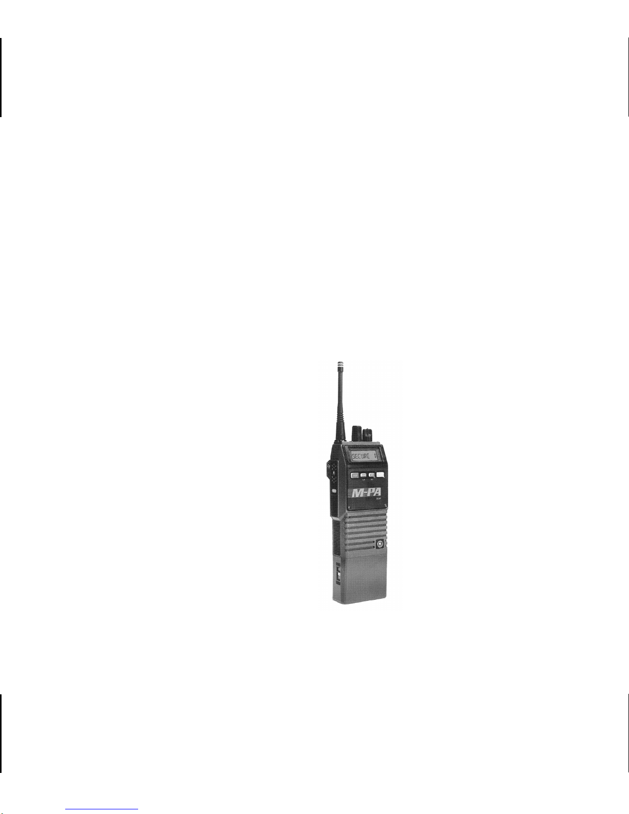
SIDE VIEW
FRONT VIEW
Figure 1 - Aegis EDACS M-PA Scan Model Radio
4

INTRODUCTION
The Aegis EDACS M-PA Scan model portable
radio is a high-performance two-way radio that provides clear voice, Aegis digital, and Aegis private
communications. The radio is also compatible with
®
Voice Guard
communication systems. Personality
programming allows maximum integration flexibility
into EDACS and conventional radio systems.
The radio must be equipped with the encrypt/decrypt option before oper ation in Aegis private or V oice
Guard modes is possible. This option allows the radio
to communicate using highly secure state-of-the-art
Aegis and Voice Guard encryption and decryption
techniques.
Operating controls on the radio include a rotatable system/group/channel control knob, rotatable
volume control, 4-button keypad, push-to-talk, emergency and monitor buttons. The on/off power switch
for the unit is located on the removable battery pack.
transmitter on, scanning, or emergency mode enabled.
The exact operation of your radio will vary depending upon the mode of operation, the radio’s
programming, and the particular radio system. Consult your radio system’s representative for particular
features that are programmed into your radio.
CONTROLS
ON/OFF SWITCH
The ON/OFF SWITCH is located on the battery
pack. Sliding this switch up will supply power to the
radio from the battery pack. An audible click will be
heard and the "ON" indicator will be exposed. When
the radio is turned on, it will perform a power-up self
test and then resume operation on the pr evious operating system, group or channel as displayed in the
LCD. Sliding the switch down will tur n the radio off.
The 8-digit alphanumeric liquid crystal display
(LCD) on the front of the radio displays the operating
status of the radio. This backlit display also has
sixteen status flags that indicate various operating
conditions such as private communications enabled,
5

VOLUME CONTROL KNOB
The VOLUME CONTROL KNOB is a rotatable
control on the top of the radio used to adjust the
receiver’s audio level in the speaker. Rotating this
knob in a clockwise direction will increase the audio
level. Counter-clockwise rotation will decrease the
audio lev el. Minimum le vels ma y be progr ammed into
the radio to prevent missed calls due to too low of a
volume setting.
CONTROL KNOB
The rotatable 16-position CONTROL KNOB located on the top of the radio may be programmed to
select trunked groups and conventional channels or
it may be programmed to select systems. See SYS-
TEM/GROUP/CHANNEL SELECTION for details.
A stop plate may be installed under the knob to
limit the maximum number of positions to less than
sixteen (16). It is normally factory installed for fifteen
(15) positions.
PTT BUTTON
Pressing the PTT BUTTON on the side of the
radio will enable the radio’s transmitter. The "TX"
status flag in the display will turn on when the radio is
transmitting. Releasing the PTT BUTTON will return
operation to receive mode.
When operating in a trunk system, the radio may
be programmed to automatically transmit (without the
operator pressing the PTT BUTTON) to maintain
communication with the site controller. The "TX"
status flag will turn on when the radio is transmitting.
MONITOR BUTTON
Trunked Mode
When operating in trunked mode, pressing the
MONITOR B UT TON after an individual call has been
received will return the radio to the group call mode.
The radio will not respond on an individual basis, but
will then transmit group calls when the PTT BUTT ON
is pressed. The radio will also automatically return to
the group call mode after the programmed call-back
time-out period expires.
In addition, this button is used to toggle between
group and regroup settings if the Dynamic Regrouping mode (with deselect capability) has been enab led
by the site controller.
6
Conventional Mode
When the radio is operating in conventional
mode, the MONITOR BUTTON is used to unsquelch
the receiver. If progr ammed f or the selected channel,
it will also toggle Channel Guard (CG) and/or Type 99
(T99) signalling on and off.
Momentarily pressing the MONITOR BUTTON
will unsquelch the receiver. If programmed, pressing
and holding the button for at least one (1) second will
toggle CG and/or T99 signalling on or off . After a T99
call has been received, pressing the MONIT OR BUTTON will reset the radio for the next call. Note: Selecting another channel will turn CG and T99
signalling back on if programmed for the channel.
EMERGENCY BUTTON
When operating in trunked mode, pressing and
holding the red EMERGENCY BUTT ON on top of the
radio for approximately one (1) second will initiate an
emergency call with voice operation on the programmed home group. If no home group is programmed into the radio , voice operation will be on the
selected group.
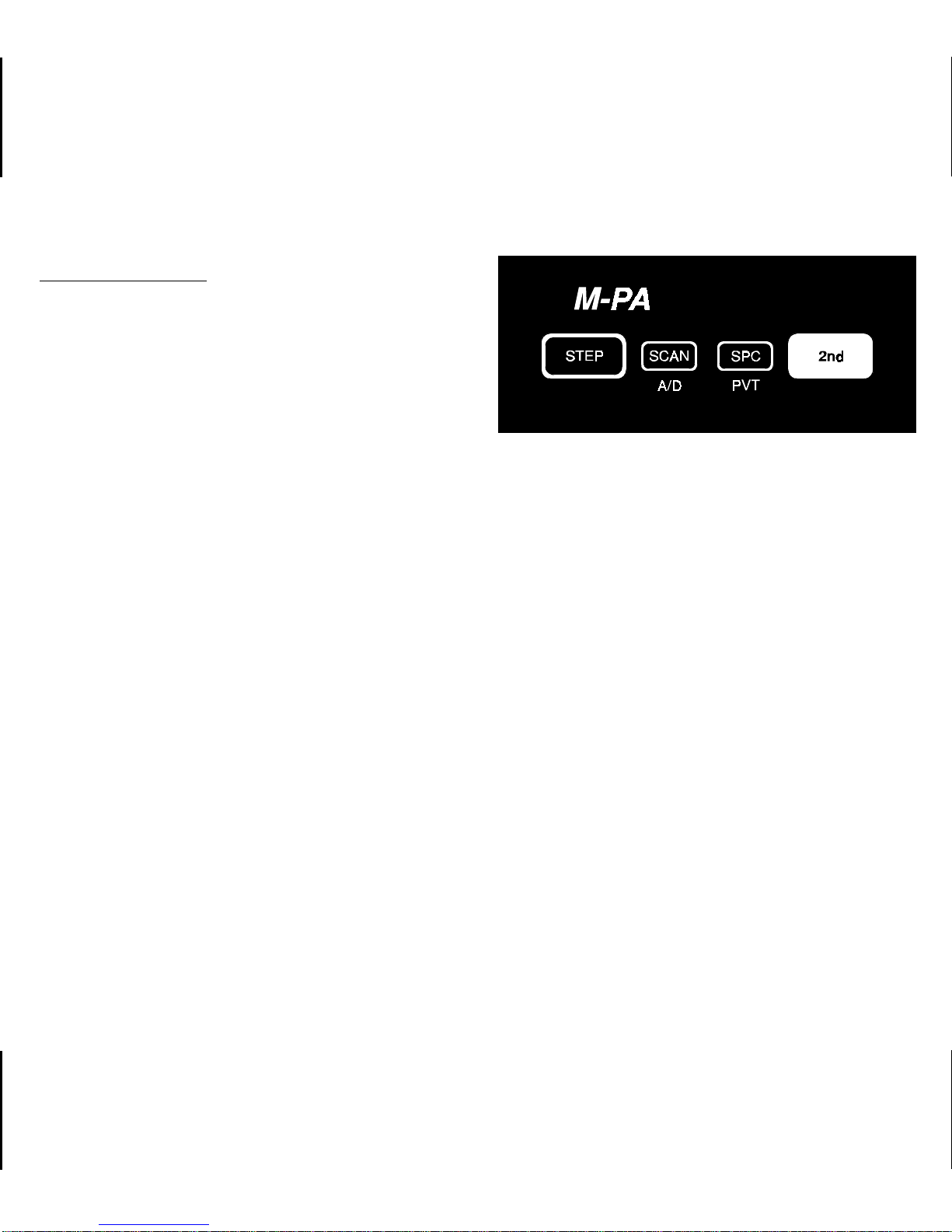
Figure 2 - Keypad
In conventional mode, initiating an emergency
call by pressing the EMERGENCY BUTTON will
cause the radio to transmit GE-STAR signalling on the
programmed emergency channel. If no emergency
channel is programmed, GE-STAR will be transmitted
on the selected channel.
STEP BUTTON
The STEP button located on the keypad may be
programmed to select trunked groups and conventional channels or it may be programmed to select
systems. See SYSTEM/GROUP/CHANNEL SELEC-
TION for details.
7

STEP is also used to scroll through the programmed special call table when the special call
mode is enabled.
SCAN BUTTON
Pressing the SCAN button on the keypad will
toggle scan operation on and off. When the radio is
scanning, the "SCN" status flag in the display will
show and all groups/channels on the scan list in the
current system will be scanned.
SPECIAL CALL BUTTON
When operating in trunked mode, pressing SPC
will switch operation from the group select mode to
the special call mode. The last selected special call
will be displayed.
While in special call mode, the next prog r amm ed
special call may be selected by pressing STEP.
Pressing 2nd then STEP will select the previous
programmed special call. The caller’s ID of the last
received individual call and the last received group
call on the selected group are also selectable using
this method. See
Special Calls for details.
2nd FUNCTION BUTTON
Two (2) of the buttons on the keypad are dualfunction buttons. Press and release the blue 2nd
function button to shift keypad selection to the A/D
and PVT buttons. The following par agr aphs describe
operation of the shifted buttons.
ADD/DELETE BUTTON (Shifted SCAN Button)
When in trunked mode, pressing and releasing
2nd and then pressing A/D (shifted SCAN button) will
add the selected group to the scan list if it is not
already on the list. Repeating this sequence will
delete the group from the list. When the selected
group is on the scan list, the "S" status flag will show
in the display.
In conventional mode , pressing and releasing 2nd
and then pressing A/D will scroll the selected channel’s scan priority between non-priority scan ("S"
status flag), priority-two scan ("2" status flag), priority-one scan ("1" status flag) and no scan (no status
flags).
8
Scan must be turned off before groups or channels can be added to or deleted from the scan list.
See SCAN BUTTON for details.
PRIVATE BUTTON (Shifted SPC Button)
Private transmit mode is enabled or disabled by
pressing and releasing 2nd and then pressing PVT
(shifted SPC button). When enabled, the "PVT"
status flag in the display will turn on.
If the radio is programmed for forced private operation, "FRCD PVT" will be display ed when 2nd-PVT
is pressed; private transmit mode is not disabled. If
the selected group or channel is not programmed for
private operation, "PVT DIS" will momentarily show in
the display when 2nd-PVT is pressed; the radio will
not change to private mode. See PRIV ATE COMMU-
NICATIONS for additional details.
INDICATORS
The radio’ s liquid crystal display (LCD) located on
the front panel has eight (8) alphanumeric characters
and sixteen (16) status flags. This display provides
indications of the current operating system, group or
channel and it displays v arious other messages such
as special call ID names or numbers, and telephone
interconnect numbers.
LCD backlighting will turn on for a shor t period
anytime an active button is pressed or the CONTR OL
KNOB is rotated. Backlighting may be programmed
to remain off at all times.
KEYPAD LOCK FEATURE
To prevent accidental activ ation of the b uttons on
the keypad, simultaneously press SCAN and SPC to
lock the keypad; "LOCKED" will be displa yed momentarily. To unlock the keypad, press SCAN and SPC a
second time; "UNLOCKED" will be displa yed momentarily .
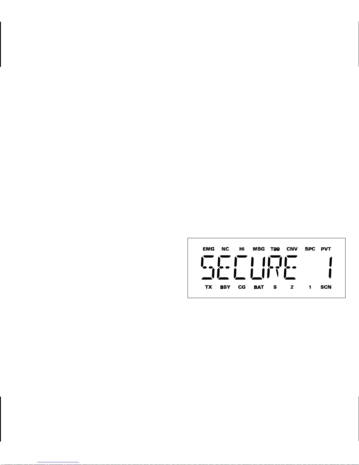
Figure 3 - Liquid Crystal Display
9

The sixteen (16) status flags located along the top
and bottom of the display indicate operating modes
and conditions as follows:
EMG EMerGency mode - On indicates an
emergency call has been initiated by the
user. Flashing indicates an emergency
call has been received.
NC No Control channel - On indicates the
radio is not receiving the trunked control
channel. Flashing indicates the trunked
system is in a failsoft condition (supervisory radios only).
CNV CoNVentional mode - On indicates the
radio is operating in the conventional
mode.
SPC SPecial Call mode - On indicates the spe-
cial call mode has been enabled (trunked
mode).
PVT PriVaTe mode - On indicates private mode
is enabled and the radio will transmit encrypted messages on the selected group
or channel. Flashing indicates an encrypted message is being received.
TX Transmitter enabled - On when the radio
is transmitting.
HI HIgh power transmit - On indicates the
selected system or channel has been programmed for high power transmit operation. Off indicates low power transmit.
MSG MeSsaGe - Flashing indicates an individ-
ual call has been received (trunked mode).
T99 Type 99 tone decode - On indicates Type
99 tone decoding is enabled on the selected conventional channel. Flashing indicates a T99 selective call has been
received and the radio must be reset to
receive another T99 call.
10
BSY BuSY - When in trunked mode, on indi-
cates the radio is receiving a call; flashing
indicates a call has been queued. In conventional mode, on indicates a carrier is
being received.
CG Channel Guard - On indicates Channel
Guard encode/decode is enabled on the
selected conventional channel.
BAT BATtery low - On indicates the battery
pack’s charge is low.
S Scan list - On indicates the selected
group/channel is on the scan list.

1 priority 1 - On indicates the selected con-
ventional channel is designated as the
priority-one scan channel.
2 priority 2 - On indicates the selected con-
ventional channel is designated as the
priority-two scan channel.
SCN SCaN mode - On indicates the radio is
scanning.
UNIVERSAL DEVICE CONNECTOR
The Universal De vice Connector (UDC) is located
on the side of the radio just above the PTT and
MONITOR B UTTONS. This connector provides connections for the external accessories such as a headset, a speaker-mik e, or an emergency lany ard. When
the radio is locked in a v ehicular charger/repeater the
UDC provides the audio and control connections
between the radio and the v ehicular charger/repeater .
The UDC is also used by the maintenance personnel
when the radio is programmed.
ALERT TONES
The radio sounds five (5) basic alert tones or
"beeps" to indicate various operating conditions. Alert
tones may be programmed to remain off at all times.
•
500 Hz Tone
•
800 Hz Tone
•
1000 Hz Tone
•
1200 Hz Tone
•
2500 Hz Tone
–
trunked failure tone - sounds
when a trunked failure has occurred (call denied, failed confirmation)
–
low battery - sounds when the
battery pack’s charge is low
–
private mode disabled - on a
conventional channel, sounds
when the PTT BUTTON is
pressed if private transmit
mode has previously been
disabled
–
alert tone - sounds when a
button is pressed and a status
change occurs
–
channel access tone - sounds
when a trunked channel has
been assigned and it is clear
to talk
–
private mode - channel access tone - sounds when the
radio is in the private transmit
mode, a trunked channel has
been assigned and it is clear
to talk
–
call queued tone - sounds
when a trunked call is queued
11

POWER-UP
OPERATION
•
Systems are selected with the STEP button;
groups and channels are selected with the
CONTROL KNOB.
After the battery pack and antenna have been
installed, turn the radio on by sliding the ON/OFF
SWITCH on the battery pack up. After the radio has
completed a power-up self-test, it will begin operation
on the last operating state as display ed in the LCD. If
programmed on, the power-up aler t tone (beep) will
be heard.
If the radio was previously operating in a trunking
system and communication with this system’ s control
channel can not be established, the "NC" status flag
will turn on. This may occur if, for example, the radio
is out of range of the previous trunking site. It may be
necessary move to another location, select another
trunking system, or a conventional channel.
SYSTEM/GROUP/CHANNEL SELECTION
or
•
Systems are selected with the CONTROL
KNOB; groups and channels are selected with
the STEP button.
STEP Button Programmed For System Selection
CONTROL KNOB Programmed For
Group/Channel Selection
System Selection
Press and release STEP to select the next system
programmed into the radio as indicated in the displa y.
To select the previous system , press and release 2nd
and then press STEP. Holding do wn STEP will cause
the radio to automatically scroll through the system
list.
The radio may be programmed with one of two
different system/group/ channel selection modes as
follows:
12
Upon reaching an end of the system list, the radio
may be programm ed to stop selection or wrap around
(go from one end to the other).
 Loading...