

Trouble Shooting Guide, Standard
Trouble Shooting Guide, Standard
Applicable for A2618s and A2618sc
Contents
1 Explanations....................................................................................................................2
2 Network Problems...........................................................................................................5
3 On/Off Problems.............................................................................................................8
4 Audio Problems.............................................................................................................10
5 Display/Illumination Problems....................................................................................13
6 Capacity/Charging Problems.......................................................................................17
7 SIM Problems................................................................................................................18
8 Key Problems.................................................................................................................20
9 Alert Problems...............................................................................................................21
10 Data Communication Problems...................................................................................22
11 Software Problems........................................................................................................22
12 Other Problems.............................................................................................................23
13 Revision History............................................................................................................24
4/00021-2/FEA 209 544/25 A Approved according to 1776-2/FEA 209 544
1 Explanations
1.1 Component Placement Reference
For component placement see doc.1078-2/FEA 209 544/25
1.2 Service Test Menu
Code to enter Service Test Menu, > * < < * < *
1.3 External connectors
External units are connected to the transceiver by means of an 11-pin connector on the bottom
of the phone.
The pin numbering is starting from the right when looking on the system connector with the
front up.
Trouble Shooting Guide, Standard
Pin Signal Function
1 DCIO DC+ pole for charging phone battery and external
accessory powering.
2 GND Digital GND and DC return.
3 VPPFLASH Flash memory Vpp /Service.
4 GND Audio signal GND, 0 V reference.
5 CFMS_PHFS Accessory Control From Mobile Station serial (ACB)
communication/ Portable Hands Free Sense.
6 CTMS Accessory Control To Mobile Station serial (ACB)
communication.
7 DFMS Data From Mobile Station, serial bus communication.
8 DTMS Data To Mobile Station, serial bus communication/
External accessory Power on
9 CTS_ON Mobile station Clear To Send/ ON REQuest
10 AFMS/RTS Audio from Mobile station/ Ready To Send
11 ATMS Audio to Mobile station
4/00021-2/FEA 209 544/25 A 2(24)

1.4 Abbreviations
B: Crystal.
C: Capacitor.
D: Digital circuit.
H: Buzzer, LED, and pads for display.
J: Connector.
L: Coil.
N: Analogue circuit, power amplifier at some units.
R: Resistor.
S: Keyboard pads.
V: Transistor, diode.
X: Contact surface on the circuit board.
Trouble Shooting Guide, Standard
Z: Filter.
DCIO: DC voltage through the system connector for charging.
GND: Ground.
RTC: Real Time Clock, the clock that keeps track of time.
SIMCONCLK: Signal from the processor used for communication to SIM, clock-signal.
SIMDCONAT: Signal from the processor used for communication to SIM, data-signal.
SIMCONRST: Signal from the processor used for communication to SIM, reset-signal.
SIM VCC: Feed voltage for SIM, 5.0 ± 0.10 V
VBATT: Battery voltage, 3.70 ± 0.5 V
VPPFLASH: Voltage to erase and program the memory. 12.0 ± 0.60 V
VCORE: DC voltage for the processor 2.4 ± 0.10 V
VCORE DSP: DC voltage for the DSP 1.8 ± 0.10 V
VDIG: DC voltage for the processor and memory, 2.75 ± 0.10 V
DC.
DC.
DC
DC.
DC.
DC.
VLCD: DC voltage for the display that controls the contrast, the voltage is generated in
the display-assembly.
VHOM: DC voltage for the radio part except the synthesiser, 3.8 ± 0.20 V
VRAD: DC voltage for the radio part, 3.8 ± 0.20 V
V380B: DC voltage for the radio part, 3.8 ± 0.20 V
VRTC: DC voltage for the real time clock, 2.35 ± 0.15 V
VVCO: DC voltage for the synthesiser, 3.8 ± 0.10 V
DC.
DC.
DC.
DC.
DC.
I2C: Communications standard for two-way communication using only 2 wires.
Unit: What the mobile telephone later in this document will be called.
4/00021-2/FEA 209 544/25 A 3(24)
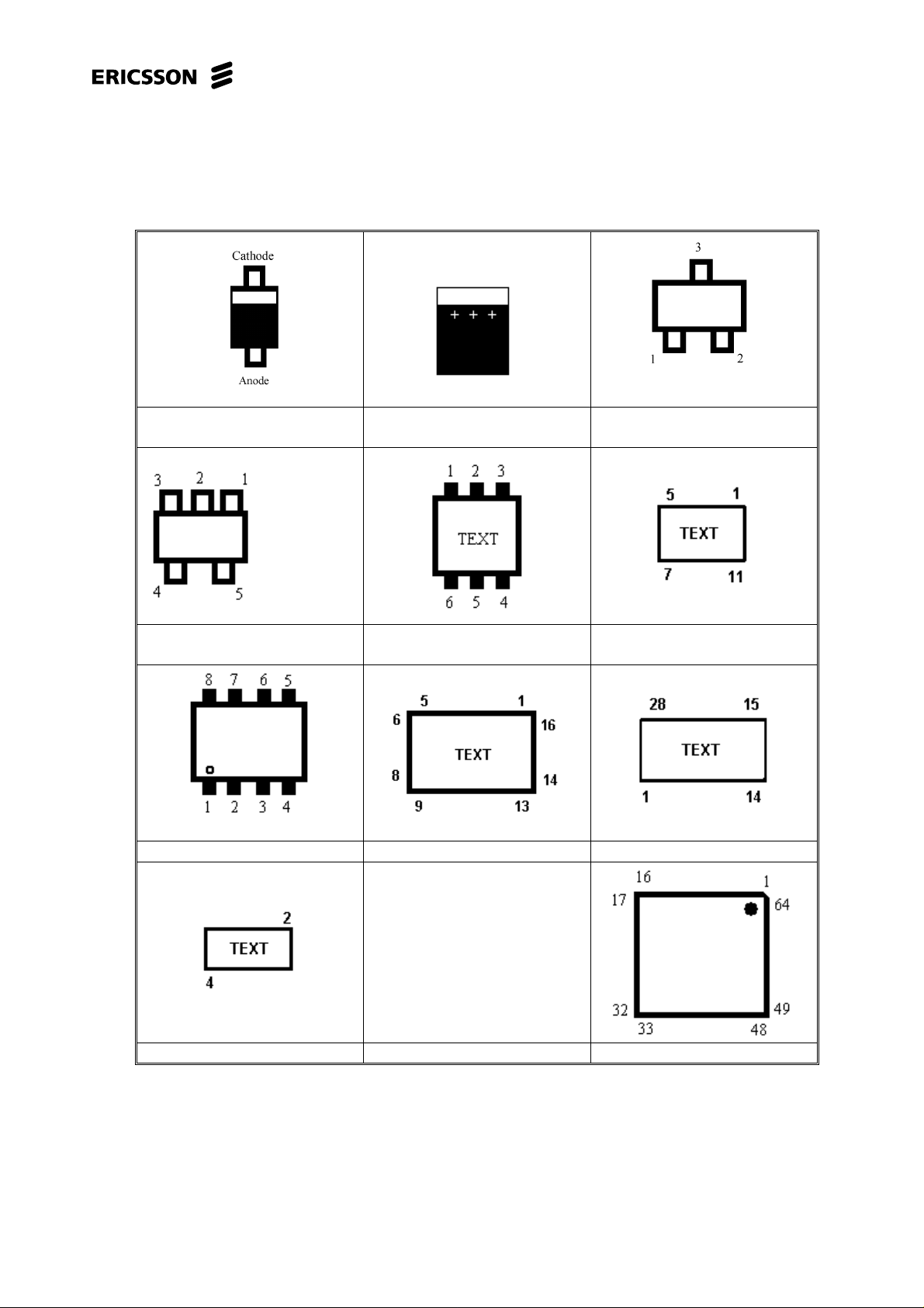
1.5 Pin placement
Trouble Shooting Guide, Standard
Single diode (PIN diode) Electrolytic capacitor.
Five pin circuit (usually volt-
age regulator).
Eight pin circuit. N200 N400
Double transistor. N392
Double diode or single
transistor
Crystal N300
4/00021-2/FEA 209 544/25 A 4(24)

2 Network Problems
2.1 Find out if the fault is RX- or TX-related
Connect the unit (with signalling program) t o a GSM test instrument and try to get
SERV at an input signal strength of -68.5 dBm.
If the unit does not get SERV, go to section 2.2.
If the unit gets SERV, go to section 2.4.
2.2 The phone does not get SERV
Open the unit and check for liquid damage.
No action is to be taken for a liquid damaged unit, send the unit on according to the local
company directives.
Trouble Shooting Guide, Standard
Make sure that the antenna connector W1 not is mechanically damaged, dirty or oxidised.
Clean it if needed.
Check the soldering of N200, N201, Z200 and Z201.
Measure the resistance over L202, L203, L204 and L206 (0 ohm).
Measure the resistance over L200, L201 (0 ohm) and R202 (270 ohm).
Replace if incorrect.
Retry to get SERV again with the settings mentioned above.
If the unit gets SERV, go to section 2.4.
If the unit still does not get SERV, the fault probably is within the LO part, or the losses in the
signal path are too large.
It is also possible that the feed voltages are incorrect, section 2.3.
Open the unit.
Power up the board and start it by pressing the On/Off key.
Measure the VRAD-voltage on C705, measure on the side close to C706.
If the voltage is incorrect, send the unit on according to the local company directives.
Measure the V380B-voltage on C706, measure on the side close to R705.
If the voltage is incorrect, send the unit on according to the local company directives.
If the voltage is correct, measure the VVCO-voltage on pin 5 of N701.
If the VVCO-voltage is correct, measure the resistances over R362 (18 kohms) and R392 (82
ohms).
If the resistances are incorrect, replace the corresponding component.
If both the resistances are correct, go to section 2.3.
4/00021-2/FEA 209 544/25 A 5(24)

Trouble Shooting Guide, Standard
If the VVCO-voltage is incorrect, measure the voltage at L700 3.7 ± 0.5 V
pin close to R705.
If the voltage on L700 is incorrect, on the pin close to R705, measure the r esistance of L700
(0 Ohm).
If the resistance is correct, send the unit on according to the local company directives.
If the resistance is too high, replace L700.
If the voltage on pin 1 of N701 is incorrect, measure the resistance of R861 (0.0 ohm) and
R704 (0.0 ohm).
If the resistance is correct, send the unit on according to the local company directives.
If it is incorrect, replace the faulty resistor.
If the voltage on V705 is 3.7 V
, on the pin close to R705, replace V705.
DC
Otherwise send the unit on according to the local company directives.
2.3 Check the feed voltages
Measure the VHOM-voltage on N300: 5, measure at C200 and N300: 13, measure at C200.
If the VHOM-voltage is incorrect, measure the resistance of Z702 (0,15 ohm).
If the resistance is incorrect, replace Z702.
measure on the
DC,
Also measure the resistance of C200, C201 (>15 kohms).
If the resistance is lower replace the faulty component.
Measure the VVCO-voltage on N300: 22, 24,33,46, 47, 57, 62.
If the VVCO-voltage is incorrect, measure the resistance of Z701 and Z300 (0,15 ohm).
If the resistance is incorrect, replace the faulty component.
Also measure the resistance of C340, C341, C342, C343, C372, C373, C374 (>100 kohms).
If the resistance is lower replace the faulty component.
Measure the VVCO-voltage on N301: 1 and 2, measure the voltage on R300, on the pin close
to C304.
If the voltage is incorrect, measure the resistance of R300 (10 ohms) and L302 (0.5 ohms).
If the resistance is incorrect, replace the faulty component.
Measure the VVCO-voltage on R331, measure on the pin close to C330.
If the voltage is incorrect, measure the resistance of R331 (10 ohms).
If the resistance is incorrect, replace R331.
If the fault remains, send the unit on according to the local company directives.
Connect a call at –68.5dBm input signal and power level 5.
If you are able to connect a call, go to section 2.5.
4/00021-2/FEA 209 544/25 A 6(24)

Trouble Shooting Guide, Standard
If you are not able to connect a call, open the unit and check for liquid damage.
No action is to be taken for a liquid damaged unit, send the unit on according to the local
company directives.
Make sure the antenna connector (W1) is not incorrectly soldered, mechanically damaged,
dirty or oxidised. Clean, re-solder or replace it if needed.
Check the soldering of N392, N391, and N390.
Try to connect a call again.
If you are able to connect a call, go to section 2.5.
If you still are not able to connect a call, send t he unit on according to the local company
directives.
2.4 Read the RX-level while a call is connected
Make sure the output power is 31-35 dBm, and the RX-level value is 40 - 46 steps.
If that is correct there is probably nothing wrong with the unit.
Lower the input signal to –102 dBm, and make sure the RX-level value is 6-12 steps and the
RX-quality value is 0-2 steps.
If RX-level and RX-quality is correct, try running the unit through the test again.
If the unit passes the test but you are not able to connect a call towards the “real” net,
make sure the unit has not been locked out of the system due to theft.
If RX-level is correct and Rx-quality is high, send the unit on according to the local company
directives.
If the RX-level value is too high the unit needs to be calibrated.
If the RX-level value is less than 38 steps at an input signal of –68.5dBm
or less than 5 steps at an input signal of –102dBm then the fault is RX-related.
Open the unit and check for liquid damage.
No action is to be taken for a liquid damaged unit, send the unit on according to the local
company directives.
Make sure the antenna connector (W1) is not incorrectly soldered, mechanically damaged,
dirty or oxidised. Clean, re-solder or replace it if needed.
Check the soldering of N200, Z200, Z201 and N201.
Measure the resistance over L202 and L204 (0.15 Ohm).
Replace if incorrect.
Remove L203, L206 and L205, then measure the resistance from pin 2 of N200 to ground
(>100 kohms). The resistance usually becomes only a few ohms when N200 is faulty.
If the resistance is incorrect, replace N200 and mount L203, L206 and L205.
If the fault still remains, send the unit on according to the local company directives.
4/00021-2/FEA 209 544/25 A 7(24)

3 On/Off Problems
Make sure the battery connector is intact, clean and fully functional.
Measure the resistance from VBATT to ground on X1:1.
It should be more than 20 kohms. If it is less, usually only a few ohms there is probably a
shortcut in N400.
Replace it if needed.
Make sure there is no liquid damage at the system connector.
No action is to be taken for a liquid damaged unit, send the unit on according to the local
company directives.
Insert a correct battery and press the On/Off key.
If the unit starts without the On/Off key being pressed, go to section 3.1.
If the unit starts, check the charging function by connecting a charger to the system connector.
Trouble Shooting Guide, Standard
If the charging function is faulty, go to chapter 6 (“Capacity/Charging problem”).
If the unit starts (lights up the background illumination, asks for SIM/Pin, seeks net…)
there is probably nothing wrong with the unit or the fault is intermittent.
If the unit does not start, connect a dummy battery to the power-supply with an Ampere-
meter, and keep the On/Off key pressed.
If the unit consumes 15-30mA, go to section 3.2.
If the unit consumes less than 15mA, go to section 3.3.
If the unit consumes 0 mA, go to section 3.4.
3.1 Starts immediately after connecting a battery
Open the unit and check for liquid damage.
No action is to be taken for a liquid damaged unit, send the unit on according to the local
company directives.
Replace the flex-film.
If the fault remains, send the unit on according to the local company directives.
3.2 Consumes 15-30 mA
Try to flash the unit.
If the fault remains, open the unit and check for liquid damage.
No action is to be taken for a liquid damaged unit, send the unit on according to the local
company directives.
If it is impossible to f lash the unit, measure the resistance of R601 (10 kohms).
If the resistance is incorrect, replace R601.
If the resistance is correct make sure that the resistance of C603 is more than 40 kohms.
If the resistance of C603 is less, replace V801.
If that does not help, replace C603.
If the resistance is correct, and it still is impossible to flash the unit, send the unit on
according to the local company directives.
4/00021-2/FEA 209 544/25 A 8(24)
 Loading...