

Page 1
INSTRUCTION SHEET
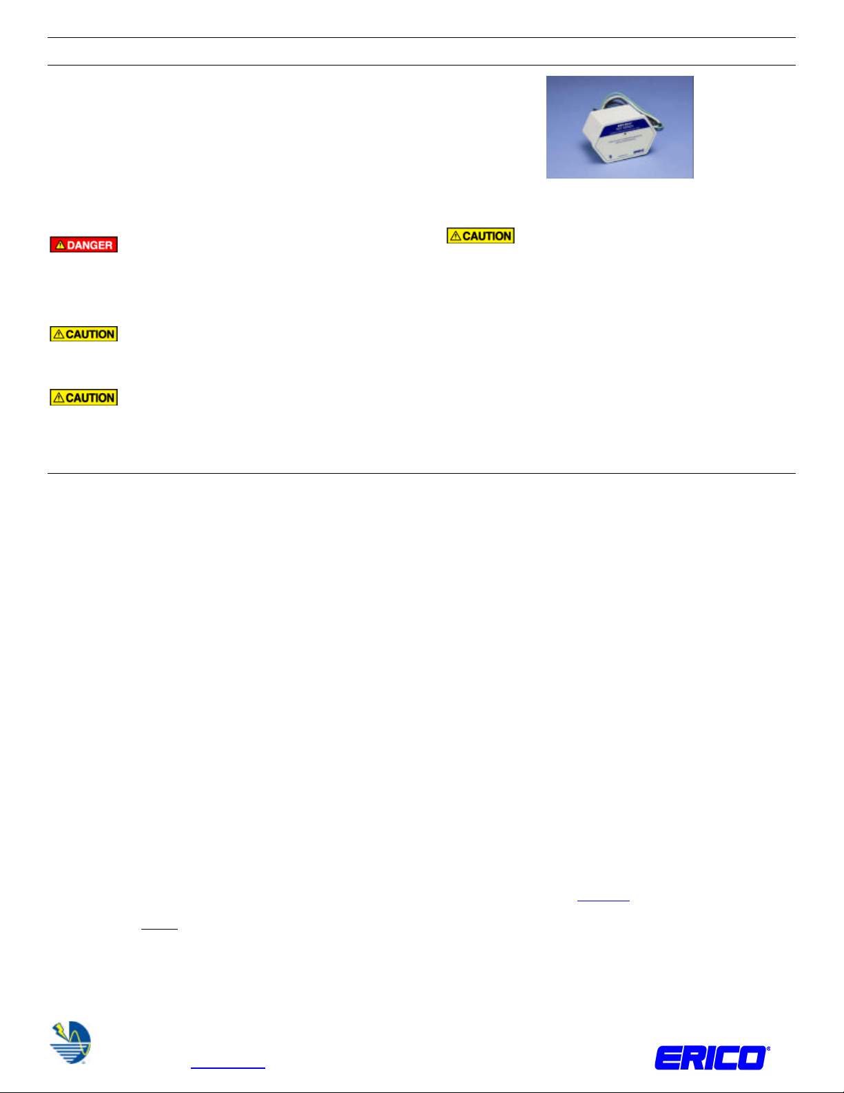
SES40P Series
The SES40P Series of Surge Protective Devices (SPD) are UL
1449 Ed. 3 Type 1 devices designed to provide protection to
service panels, load centers or where the SPD is directly
connected to the electrical device requiring protection. The
SES40P Series SPD is UL Type 4X rated, and is supplied with
24” wiring leads for a direct hardwired connection. Maximum
protection will only be achieved if the SPD is properly installed.
Please carefully read and follow the installation instructions.
DANGER: Electrical shock or burn hazard.
Installation of this SPD should only be made by qualified
personnel. Failure to lockout electrical power during
installation or maintenance can result in fatal electrocution or
severe burns.
CAUTION: Check to make sure system voltages
do not exceed the SPD voltage requirement and ratings and
that the correct SPD voltage/model has been selected.
CAUTION: This unit must be installed in
accordance with the National Electrical Code (NEC)
SES40P Series SPD
CAUTION: Ungrounded power systems are
inherently unstable and can produce excessively high line-toground voltages during certain fault conditions. During these
fault conditions any electrical equipment, including an SPD,
may be subjected to voltages that exceed their designed
ratings. This information is being provided to the user so that
an informed decision can be made before installing any
electrical equipment on an ungrounded power system.
NOTE: Do not cut wires until the SPD is mounted and
minimum wire lengths have been verified. All connection leads
should be cut to minimum possible length; never coil or push
aside excess length.
(ANSI/NFPA-70) and all other applicable codes.
Installation Instructions
1. Verify system voltage Confirm that the SPD is correctly
rated for the system to which it is to be connected by
comparing measured voltages to the SPD voltage ratings
shown on the product rating label. The measured voltage
should match the nominal operating voltage of the product,
the maximum continuous operating voltage (MCOV)
specifications must not be exceeded.
2. Identify proper location for the SPD. Locate the unit as
close as possible to the panel being protected to minimize
lead lengths. If possible, avoid sharp bends in wires. The
SES40P is supplied with an integral ¾” threaded nipple and
conduit locknut. The SES40P can be direct nippled into the
panel, and secured with the locknut. If required, use
appropriate watertight conduit hubs to maintain the
SPD/panel UL enclosure rating.
3. Connect ground. Attach the grounding conductor to the
panel’s ground bus. Wire length should be minimized to
improve performance. There is no minimum wire length
requirement.
DANGER
ELECTRICAL SHOCK OR BURN HAZARD. HAZARDOUS VOLTAGES EXIST INTERNAL TO THE SES40P. THIS UNIT SHOULD BE INSTALLED AND SERVICED ONLY BY QUALIFIED PERSONNEL IN
CONFORMANCE WITH ALL GOVERNING CODES AND INSTRUCTIONS. FAILURE TO LOCKOUT ELECTRICAL POWER DURING INSTALLATION OR MAINTENANCE CAN RESULT IN FATAL
ELECTROCUTION, SEVERE BURNS, OR OTHER INJURIES. BEFORE WORKING WITH OR MAKING ANY CONNECTIONS TO THIS DEVICE, BE SURE THAT POWER HAS BEEN REMOVED FROM ALL
ASSOCIATED WIRING, ELECTRICAL PANELS, AND OTHER ELECTRICAL EQUIPMENT.
1. The power supply to the SES40P should always be turned (and locked) OFF before the unit is accessed for any reason.
2. Prior to installation, ensure that the SES40P is of the correct voltage, current, phasing, and frequency for the applicable rating of the power distribution system.
3. This unit may be installed on the load side or the line side of the main over-current protection provided that it is not installed on services with more than 200kA fault current capability.
4. Diagrams are for reference only. Schematics are representative of typical applications and are only to be used for reference.
WARNING
1. ERICO products shall be installed and used only as indicated in ERICO product instruction sheets and training materials. Instruction sheets are available at www.erico.com and from your ERICO customer service
representative.
2. ERICO products must never be used for a purpose other than the purpose for which they were designed or in a manner that exceeds specified load ratings.
3. All instructions must be completely followed to ensure proper and safe installation and performance.
4. Improper installation, misuse, misapplication or other failure to completely follow ERICO’s instructions and warnings may cause product malfunction, property damage, serious bodily injury and death.
SAFETY INSTRUCTIONS: All governing codes and regulations and those required by the job site must be observed. Always use appropriate safety equipment such as eye protection, hard hat, and gloves as appropriate to
the application.
ANSI is a registered trademark of American National Standards Institute
NEC is a registered trademark of, and National Electrical Code (NEC) standard is a copyright of the National Fire Protection Association
NFPA is a registered trademark of National Fire Protection Association
UL is a registered trademark of Underwriters Laboratories, Inc.
CADDY, CADWELD, CRITEC, ERICO, ERIFLEX, ERITECH and LENTON are registered trademarks of ERICO International Corporation
Note 1: The SES40120/240SP does not have a grounding
conductor, it utilizes a grounded (neutral) conductor for
operation.
Note 2: For isolated ground systems, bond the grounding
conductor from the SES40P unit to the non-isolated
equipment ground, not the isolated equipment ground.
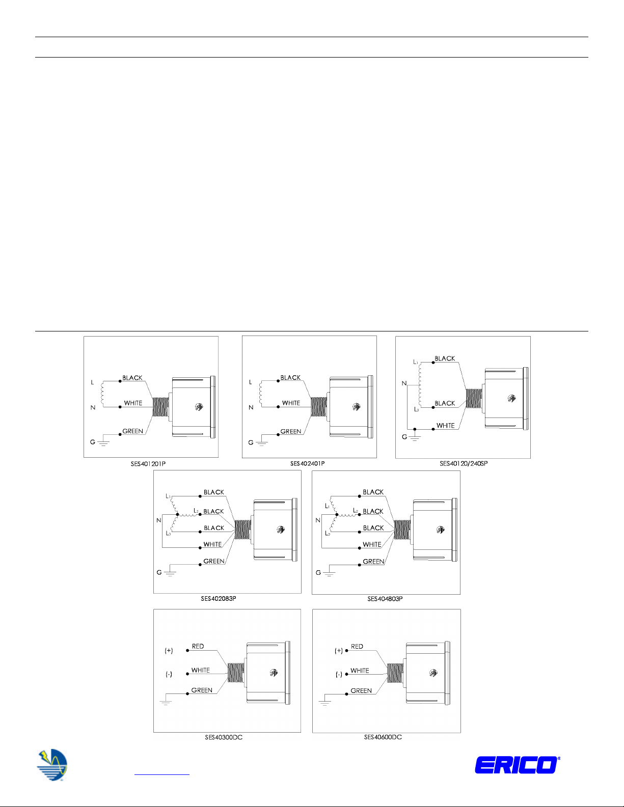
4. AC Rated Units: Connect neutral and phase
conductors. The SES40P SPDs are supplied with 24” of
12AWG leads for a direct hardwired connection. With the
POWER OFF, connect the neutral conductor of the SPD to
the neutral lug in the panel. Connect each black lead
(phasing is not critical to the operation). Wire lengths
should be minimized to improve performance. There is no
minimum wire length requirement. The SES40P Series of
SPDs are rated as a UL 1449 Ed 3 Type 1 device and
therefore no overcurrent protection is required. However, if
overcurrent protection is desired, then a 20A fuse or circuit
breaker is recommended.
www.erico.com IP8213_B 1 of 2 2011 ERICO International Corporation
TECHNICAL SUPPORT:
Page 2
Note:
INSTRUCTION SHEET
The rated SES40P Series of SPDs are suitable for use
on a circuit capable of delivering not more than
200kA
rms
DC Rated Units: Connect line conductors (For Use In
Photovoltaic Systems Only). The line conductors for the
DC rated units are white and red in color. With the POWER
OFF, connect white to (–) and red to (+). The SES40P
Series of SPDs are rated as a UL 1449 Ed 3 Type 1 device
and therefore no overcurrent protection is required.
However, if overcurrent protection is desired, then a 20A
DC rated fuse is recommended.
The DC rated SES40P Series of SPDs are suitable for
use on a circuit capable of delivering not more than
100kA.
5. Connector and Lugs Pressure terminals or pressure
splicing connectors and soldering lugs used in the
installation of the SES40P unit shall be identified as being
suitable for use with the conductors. Conductors of
dissimilar metals shall not be intermixed in a terminal or
Wiring Diagrams
splicing connector where physical contact occurs between
dissimilar conductors unless the device is identified for the
purpose and conditions of use.
6. Activate unit. When the power is applied, the red LED
diagnostic light(s) will indicate that the unit is operational
and protection is being provided. If any LED does not
illuminate, please recheck all connections
7. Mounting Bracket. For installations requiring a
supplemental mounting bracket, order part number
SES40BRK and follow the supplied instructions.
8. LED Diagnostics. The red LED diagnostic light(s) are
illuminated when the unit is providing protection. If one or
more red LED light(s) extinguish, check the power
connections (and overcurrent protection device if present).
If power is being correctly supplied, and one or more of the
LEDs are still not illuminated, the unit requires prompt
replacement. Please contact your local ERICO
representative.
For 3-Phase, 4-Wire
480V WYE (no
neutral) systems or
3-Phase 240V and
480V DELTA
systems, cut neutral
wire and cap with
listed method.
See Note
See Note
www.erico.com IP8213_B 2 of 2
TECHNICAL SUPPORT:
2011 ERICO International Corporation
 Loading...