


LENTON INTERLOK Rebar Splicing System
Instruction Manual
LENTON® INTERLOK
Rebar Splicing System
Revised January 2013
PDF137_B


Table of Contents
General and Safety Information ii
Foreword iii
Overview iv
1. Precaster Installation PAGE
1.1 Components List 1
1.2 Coupler Dimensions & Determining Cut Length of Reinforcing Steel
– Imperial Units 2
– Metric Units 3
1.3 Coupler Dimensions and Determining Cut Length of Reinforcing Steel – Transitions
– Imperial Units 4
– Metric Units 5
1.4 How to Determine Inlet and Outlet Straight Tube Lengths 6
1.5 Locating Inlet/Outlet Tubes for Pump Filling Application 7-8
1.6 Coupler Installation Procedures at Precasting Plant 9-10
2. Job Site Grouting
®
2.1 Quantity of LENTON
INTERLOK Splices per Bag of HY10L 11
2.2 HY10L Mixing Instructions 12-13
2.3 Hot and Cold Weather Grouting Instructions 14-15
2.4 Gravity Fill Installation Instructions for HY10L Filler Material 16-17
2.5 Pump Fill Installation Instructions for HY10L Filler Material 18-19
2.6 Grouting Troubleshooting Guide 20
2.7 HY10L Filler Material Product Specification* 21
*MSDS Available – Contact ERICO
www.erico.com
i

IMPORTANT – General and Safety Information
A. Only ERICO authorized materials should be used to make LENTON® INTERLOK Rebar Splices.
1. Do not splice except as detailed in the instructions.
2. Do not alter materials without manufacturer authorization.
3. Do not substitute for ERICO authorized materials.
Failure to comply with the above may result in hazards to the individual, improper splices, or damage to items being connected.
B. Make splices in accordance with described splicing procedures and in consideration of surrounding conditions and personnel.
Refer to the HY10L MSDS prior to beginning work with the grout.
1. Personnel should be properly trained in the use of this product.
2. Avoid breathing concentrations of grout dust as it may be hazardous to health. Refer to MSDS for control measures.
3. Avoid skin contact with grout slurry.
C. Unusual applications or conditions may exist which require special considerations.
1. Provide adequate ventilation where natural air flow is not sufficient to prevent personnel from breathing
concentrations of dust.
D.
Storage of HY10L Filler Material should be in a clean, dry, secure area and should be restricted to access by authorized personnel
only. Discard any torn, wet, or otherwise damaged bags. Discard any bags which have become wet or where material clumping
is observed. Material consistency should be that of a free flowing fine powder.
E. To determine the date of HY10L manufacture, refer to the lot number located on the end panel of each bag.
The manufacturing date can be determined as shown below:
X YY MM DD ZZ
Example A1210051J: Material produced October 5, 2012 batch 1 of the day. The 1st Alpha character “A” is a production
code. The last character “J” is an optional placeholder for the manufacturer (it may or may not be used and printed on
the bag).
DO NOT USE any HY10L which is in excess of 1 year beyond the manufacturer’s date noted on the package.
F. Refer to grout mixing directions located on the bag for proper mixing guidelines or contact ERICO.
G. Refer to Pump Fill or Gravity Fill Installation Instructions located in this Manual for proper installation guidelines.
H. The recommended temperature range of the HY10L Filler Material is 50 to 80°F (10 to 27°C). At no time during placing and
curing should the temperature of the coupler, rebar, and HY10L be allowed to be outside the range of 40 to 90°F (4 to 32°C).
I. Do not use more than 13.5% water by weight (0.8 gallons or 3.0L per 50 lb. (22.7Kg) bag) or obtain an ERICO Flow
Template reading of greater than 6.5” (16.5cm). Do not add any additives or admixtures to the HY10L.
J. Keep walls and panels undisturbed for at least 24 hours [at 68°F (20°C)]. Movement during curing will result in decreased
splice performance. Temperatures below 50°F (10°C) considerably increase the time it takes freshly placed grout to develop
strength. Therefore, there is a risk of damage or collapse if the structure is loaded before it develops adequate strength.
This
by the structural
K. The HY10L Filler Material is designed to be used with the LENTON INTERLOK Rebar Splicing System. Unauthorized use of
other grouts will void all warranties, whether expressed or implied.
L. While working on the job site, observe all Federal, State, and Local safety regulations.
1. Wear a hard hat and safety glasses.
2. Wear gloves to avoid cuts.
3. Prior to installing connections, read and understand all operating, mixing, and safety instructions found in this Manual
and on the HY10L bag.
M. Deviations from the specified recommendations outlined in this manual will void all warranties. It is the responsibility of the
user(s) to observe proper grouting conditions, (e.g., temperature, water to cement ratio, placing consistency, etc.)
quality workmanship.
N. ERICO reserves the right to revise these documents contained herein for any reason, including but not limited to conformity
To assure that you have the most recent edition of this manual, contact ERICO.
strength may vary depending on the structural loading and the temperature. Therefore, the strength must be determined
engineer and should be based upon the expected construction loading.
and utilize
with standards established by various agencies, utilization of advances in the state of technical arts, or the reflection of
changes in the design of any components, techniques, or procedures described or referred to herein.
www.erico.com
ii

Foreword
The LENTON® INTERLOK System has been designed to exceed the ACI® 318 Building Code Type 1 requirement of
developing, in
A615 Grade 60 rebar specifications.
and AS3600 for specified tensile strength performance. In order to achieve these stress levels, it is imperative that
all procedures shown in this manual and on the HY10L bag are closely followed.
HY10L High-Strength Filler Material has been developed exclusively for use in the
Use of other grouts will void all warranties and product claims, both expressed or implied.
Before beginning any project, we ask that the ENTIRE manual be reviewed, and thoroughly understood.
For technical assistance, on the LENTON INTERLOK System, or other ERICO Reinforcing Steel Splices,
please contact your local ERICO office.
both tension and compression, a minimum of 125 percent of specified yield for ASTM® A706 and
In addition, the system will meet the requirements for ACI 318 Type 2, BS8110
LENTON
INTERLOK system.
WARNING
1. ERICO products shall be installed and used only as indicated in ERICO product instruction sheets and training materials. Instruction sheets are available at www.erico.com and from your ERICO customer
service representative.
2. ERICO products must never be used for a purpose other than the purpose for which they were designed or in a manner that exceeds specified load ratings.
3. All instructions must be completely followed to ensure proper and safe installation and performance.
4. Improper installation, misuse, misapplication or other failure to completely follow ERICO’s instructions and warnings may cause product malfunction, property damage, serious bodily injury and death.
The customer is responsible for:
a. Conformance to all governing codes.
b. The integrity of structures to which the products are attached, including their capability of safely accepting the loads imposed, as evaluated by a qualified engineer.
c. Using appropriate industry standard hardware as noted above.
SAFETY INSTRUCTIONS:
All governing codes and regulations and those required by the job site must be observed. Always use appropriate safety equipment such as eye protection, hard hat, and gloves as appropriate to the application.
www.erico.com
iii

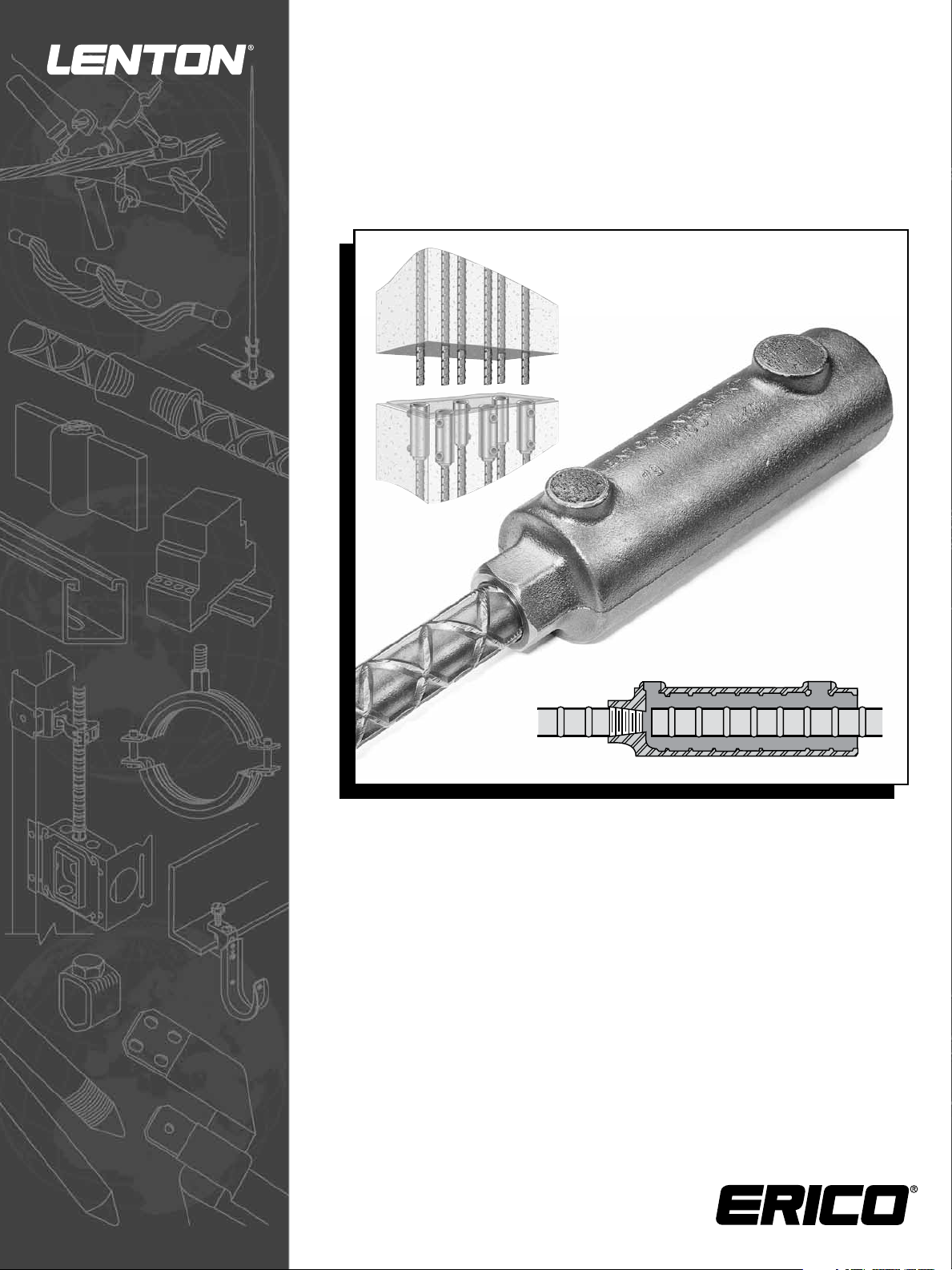
Overview
The LENTON® INTERLOK Mechanical Reinforcing Steel Splice is designed to connect #5 (16 mm) through #18 (57 mm) rebar,
conforming to ASTM
the LENTON
®
taper threaded system in conjunction with a special
rial (grout). Assembly of the connection is normally
the coupler at a precaster’s plant prior to placement of concrete in the precast member. The connection is completed at
job site, where the exposed dowel of the adjoining panel is positioned within the interior of the coupler. The filler material
®
A615/A615M, A706/A706M, BS4449, CSA G30.18 or AS1302 standards. The connection incorporates
high-early strength cementitious volume stable filler mate-
done in two separate stages: The LENTON threaded end is fastened to
the
is
either poured or pumped into the cylindrical end of the coupler. The coupler can be oriented in either a vertical, inclined or
horizontal position.
The filler material is a special ready-to-use grout, designed to maintain fluidity for an extended period of time while achieving
a high-early-strength. It is a metallic, volume-stable, material capable of developing in excess of 8,500 psi (58.6 MPa)
compressive strength at 28 days. To ensure a proper connection, the addition of water must be maintained in strict
accordance with ERICO recommended procedures. In addition, the temperature of the grout during placing and curing must
be maintained within the recommended guidelines. Misapplication or use of grouts other than ERICO brand of HY10L without ERICO approval voids all warranties, both expressed or implied.
The coupler is produced as a casting and LENTON taper threads are machined under strict Quality Control guidelines. Taper
threading of the rebar ends are produced using ERICO’s equipment. Prethreaded bars can be provided from ERICO’s network
of threading centers, or by positioning a threader at the precasters plant. The threads are right hand and tapered to match
the accompanying coupler.
When assembled in accordance with ERICO recommended procedures, the splice will meet or exceed the ACI 318, BS8110,
AS3600, UBC
®
or IBC® Building Code requirements.
www.erico.com
iv
Precaster Installation
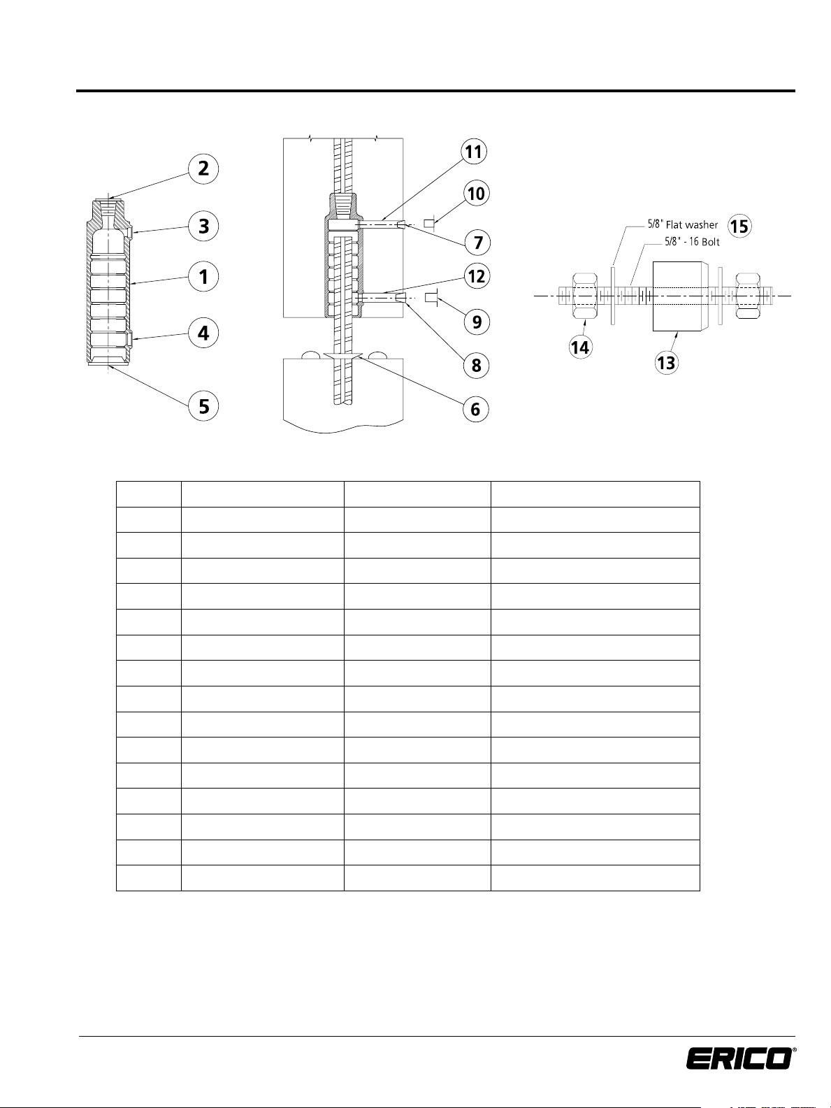
I.I Component List:
Item No. Description Standard Item Included Separate Order
®
1 LENTON
INTERLOK Coupler Standard
2 Thread Protector Standard
3 1/2” Outlet Plug Order separately or Obtain locally
4 3/4” Inlet Plug Order separately or Obtain locally
5 Dust Cap Order separately or Obtain locally
6 Sealing Disc Order separately
7 1/2” (13mm) Plastic Dust Cap Order separately or Obtain locally
8 3/4” (19mm) Plastic Dust Cap Order separately or Obtain locally
9 3/4” (19mm) Rubber Stopper Order separately or Obtain locally
10 1/2” (13mm) Rubber Stopper Order separately or Obtain locally
11 1/2” (13mm) SCH40 PVC Obtain locally
12 3/4” (19mm) SCH40 PVC Obtain locally
13 Urethane Grommet
14 5/8-16 x 3-1/2 Bolt & Nut
15 5/8 Flat Washer
a
a
a
Order separately
Order separately
Order separately
c
c
b
b
b
b
b
b
b
a Included with Form Mounting Fixture
b Non-stock item typically found locally
c Not supplied by ERICO
www.erico.com
1
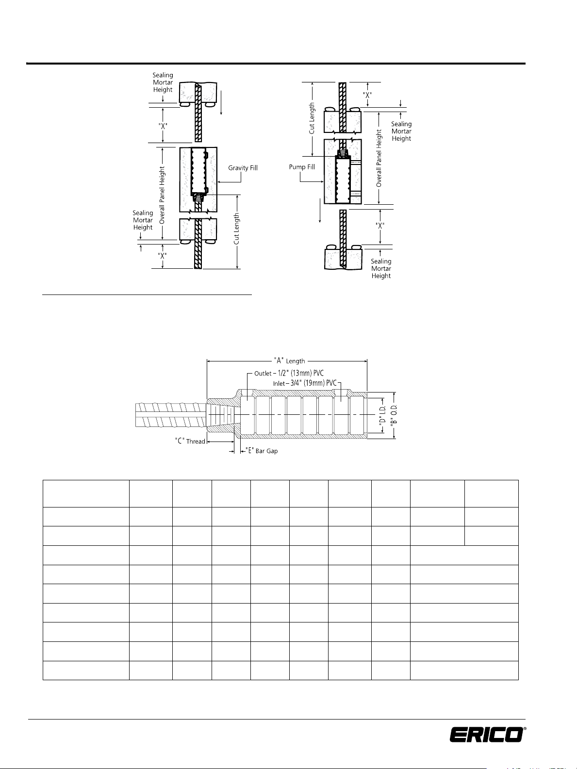
1.2 Coupler Dimensions and Determining Cut
Length of Reinforcing Steel – Imperial Units
To Determine Typical Cut Length of Reinforcing Steel:
Maximum Cut Length
Gravity or Pump Condition = [Overall Panel Height - E] + Sealing Mortar Height
Minimum Cut Length = Maximum Cut Length - 1 Bar Diameter Note: For last lift, reduce cut length as
Dowel Length = X + Sealing Mortar Height determined by design requirements
Imperial Units:
Rebar Size
in-lb Canadian
#5 15M LK5 7-13/16” 2-9 /16” 7/8” 1-7/8” 13 /16“ 6-1/ 8” 5-1/4” 5-1/2”
#6 20M LK6 7-13/16” 2-9 /16” 1-1/ 8” 1-7/8” 9/16” 6-1/8 ” 5 -1/4” 5-3/8”
#7 --- LK7 7-13/16” 2-9 /16” 1-1/4” 1-7/8” 7/16” 6-1/8” 5-1/4”
#8 25M LK8 8-5/8” 2 -11/16” 1-3/8” 2” 1/4” 7” 6”
#9 30M LK9 9 -3/4” 2-13/ 16” 1-1/ 2” 2-1/8” 1/4” 8” 6-7/8”
#10 --- L K10 10-13 /16” 3” 1-9/16” 2-5/16” 1/4” 9” 7-3/4”
#11 35M LK11 11-15 /1 6” 3-1/8” 1 -11/16” 2-7/16” 3/8” 9-7/8” 8-1/2”
#14 45M LK T14 15 -3/16” 3-11/ 16” 2-1/8” 2-3/4” 5/16” 12-3/4” 11”
#18 55M LKT18 20-5/16” 4-1/2” 2-3/4” 3-1/4” 9/16” 17” 14-3/4”
* “X” Min. Type 1 will develop 125% of the specified yield strength of the rebar in tension and compression ( 125% f
** “X” Min. Type 2 meets Type 1 and will develop the specified tensile strength of the rebar in tension ( f
Contact ERICO for rebar sizes not listed.
www.erico.com
Coupler
Part No.
“A” “B” “C” “D”
2
Reference
).
u
“E”
“X”
Max.
).
y
“X” Min.
Typ e 1*
“X” Min.
Type 2**
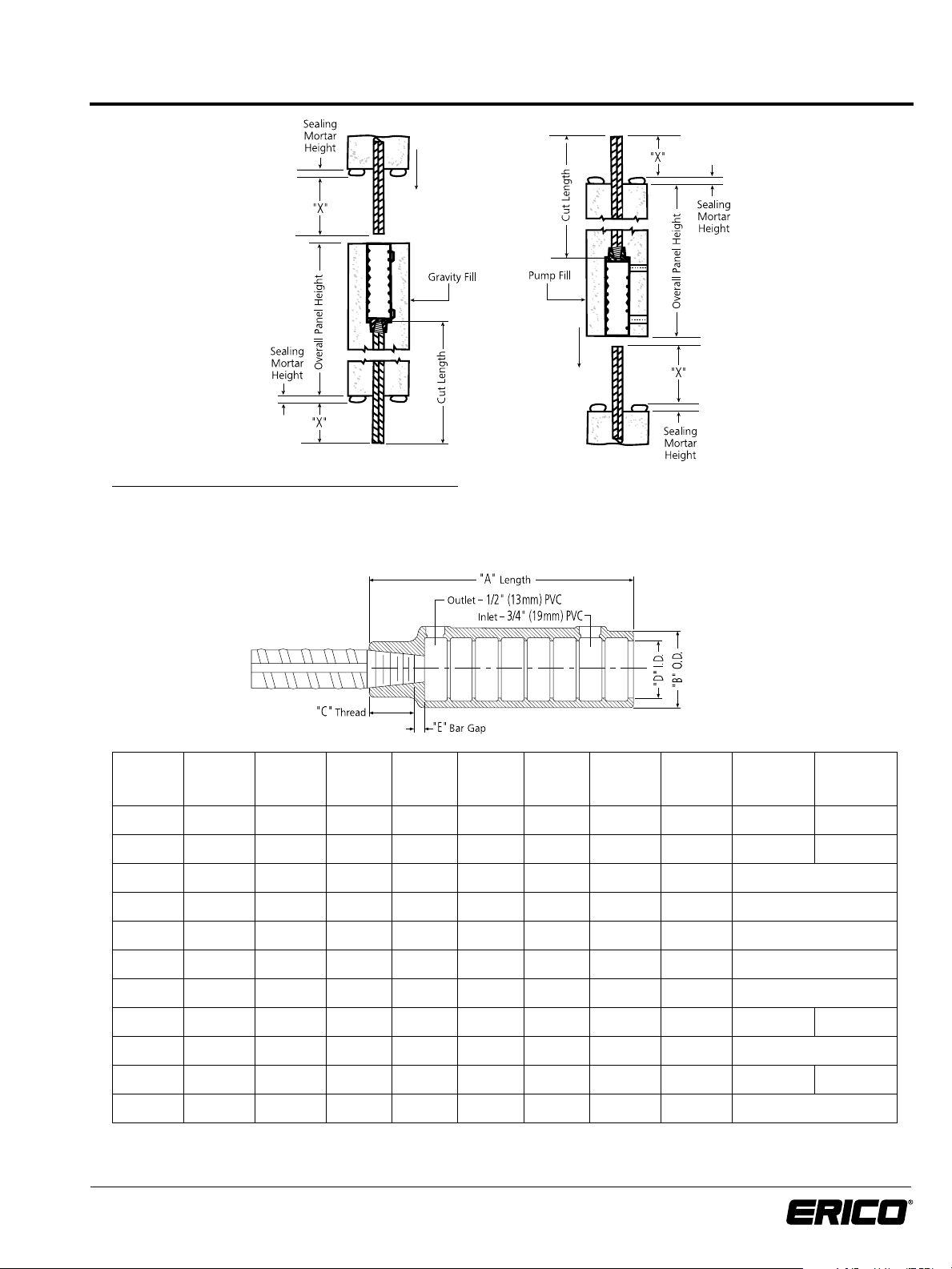
1.2 Coupler Dimensions and Determining Cut
Length of Reinforcing Steel – Metric Units
To Determine Typical Cut Length of Reinforcing Steel:
Maximum Cut Length
Gravity or Pump Condition = [Overall Panel Height - E] + Sealing Mortar Height
Minimum Cut Length = Maximum Cut Length - 1 Bar Diameter Note: For last lift, reduce cut length as
Dowel Length = X + Sealing Mortar Height determined by design requirements
Metric Units:
Rebar Size mmCoupler
Part No.
16 LK5 145575 199 65 22 48 21 156 134 140
20 LK6 145580 199 65 29 48 14 156 134 136
22 LK7 145585 199 65 32 48 11 156 134
25 LK8 145590 219 68 35 51 6 178 153
28 LK9 145595 248 72 38 54 6 203 175
32 LK10 145600 275 76 40 59 6 229 197
36 LK11 145605 303 79 43 62 10 251 215
40 LK40 145610 386 94 58 70 4 324 284 318
43 LKT14 145611 386 94 54 70 8 324 281
50 LKT50 145615 516 114 71 83 13 432 382 426
57 LKT18 145620 516 114 70 83 14 432 375
* “X” Min. Type 1 will develop 125% of the specified yield strength of the rebar in tension and compression ( 125% f
** “X” Min. Type 2 meets Type 1 and will develop the specified tensile strength of the rebar in tension ( f
Contact ERICO for rebar sizes not listed.
Coupler
Article
No.
“A”
mm
“B”
mm
“C”
mm
“D”
mm
).
u
“E”
Reference
mm
). All table dimension in mm
y
“X”
Max.
mm
“X” Min.
Typ e 1*
mm
“X” Min.
Type 2**
mm
www.erico.com
3
 Loading...