

Page 1
Instruction and
Maintenance Manual
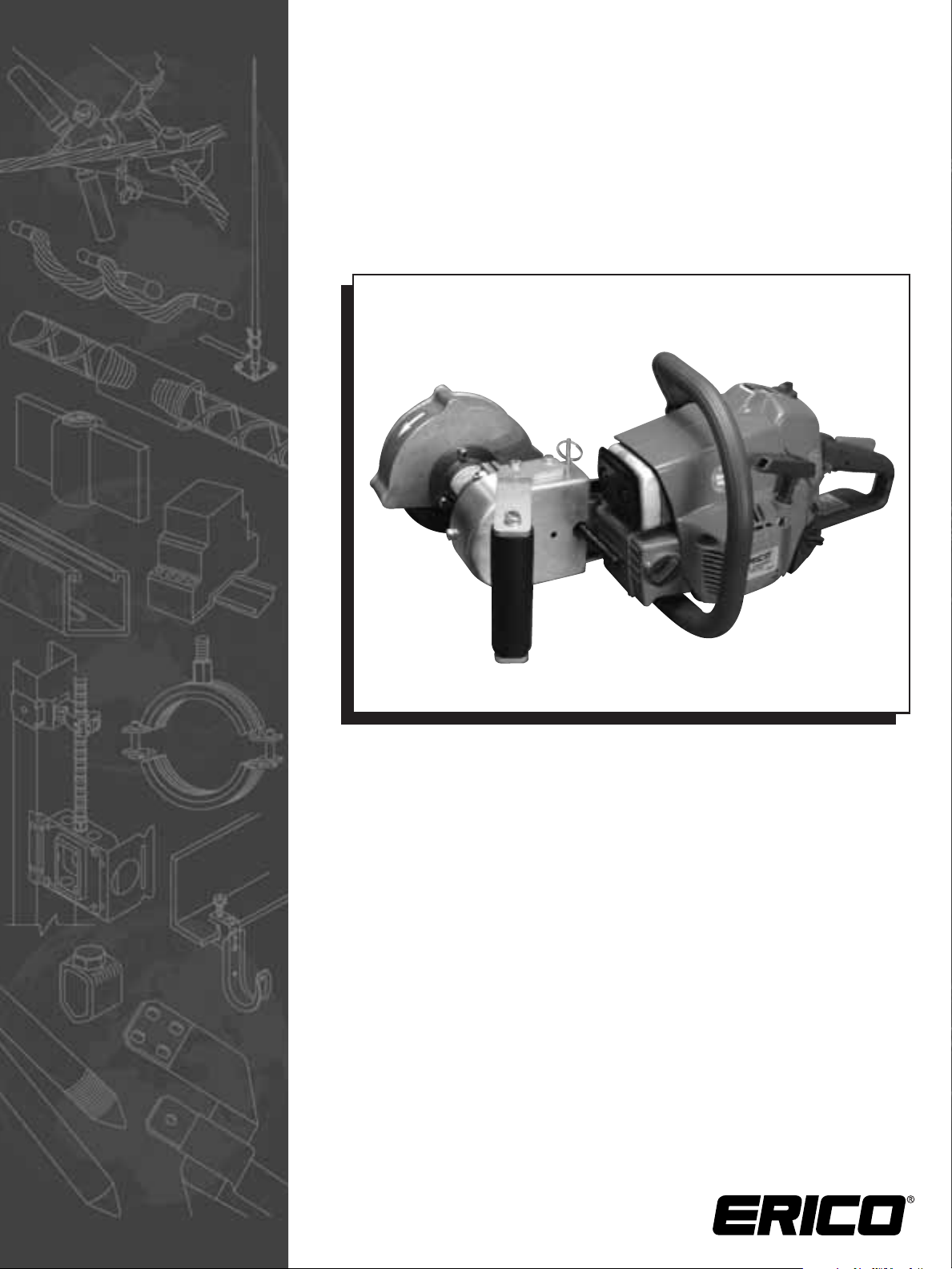
RAIL GRINDER
Model SBG150
Page 2

Page 3

i
www.erico.com
WARNING:
1. ERICO products shall be installed and used only as indicated in ERICO product instruction sheets and training materials.
Instruction sheets are available at www.erico.com and from your ERICO customer service representative.
2. ERICO products must never be used for a purpose other than the purpose for which they were designed or in a manner
that exceeds specified load ratings.
3. All instructions must be completely
followed to ensure proper and safe installation and performance.
4. Improper installation, misuse, misapplication or other failure to completely follow ERICO’s instructions and warnings
may cause product malfunction, property damage, serious bodily injury and death.
SAFETY INSTRUCTIONS:
All governing codes and regulations and those required by the job site must be observed. Always use appropriate safety equipment
such as eye protection, hard hat, and gloves as appropriate to the application.
For Service, call 1-800-447-RAIL (7245).
General Safety Information ............................................................................................. ii-iii
Fuel Mix ............................................................................................................................. iv
Specifications ..................................................................................................................... 1
Ordering Spare Parts ........................................................................................................... 1
Warranty / Service ............................................................................................................... 1
Identifying Parts of the Tool ................................................................................................ 2
Instructions Before Starting ................................................................................................. 3
Operating the Rail Grinder .................................................................................................. 3
Rail Grinding Procedure ...................................................................................................... 4
Tool Maintenance Schedule ................................................................................................ 5
Torque Schedule ................................................................................................................. 5
Trouble Shooting Chart ....................................................................................................... 6
Carburetor Adjustments ..................................................................................................... 6
Drive Belt ............................................................................................................................ 7
Air Filter Removal ............................................................................................................... 8
Grinding Wheel Removal .................................................................................................... 8
Accessories ......................................................................................................................... 9
SBG150 Rail Grinder Parts List .......................................................................................... 10
SBG150 Rail Grinder Exploded View ................................................................................. 11
ERICO
®
Rail Products Limited Warranty .............................................................................. 12
TABLE OF CONTENTS
Page 4

ii
www.erico.com
GENERAL SAFETY INFORMATION
Read and follow all safety instructions before operating or performing maintenance on the equipment.
DEFINITIONS OF FLAG WORDS:
DANGER: Indicates an imminent hazardous situation, which, if not avoided, will result in death or serious injury.
Its use is limited to the most extreme situation.
WARNING: Indicates a potentially hazardous situation, which, if not avoided, could result in death or serious injury.
CAUTION: Indicates a hazardous situation, which, if not avoided, will result in minor or moderate injury.
It is also used to alert against unsafe practices.
NOTICE: Is used only with alerts that warn against property damage.
During the operation of the equipment, the user must be familiar with and follow all applicable statutes, codes, and regulations
governing the workplace.
DANGER
EXPLOSIVE DISINTEGRATION HAZARD: Defective grinding wheels can explosively disintegrate when turning at high speeds
causing death or serious injury from flying debris. Prior to use, always check wheel for soundness by tapping with a hammer or
wrench; wheels with nicks, flat spots or excessive wear should be discarded. Never operate the wheel above its rated speed. Ensure
that all guards are in place prior to operating the tool. Always operate the grinder in a position that places the guard between the
wheel and the operator. New wheels should be run at operating speed for one minute before any actual grinding. Never grind with
the side of a conventional straight or Type 1 grinding wheel.
EXPLOSION, FLAMMABILITY HAZARD: Failure to refuel the equipment away from open flame, spark generators, or other
ignition sources, including smoking, will result in a fatal or serious injury accident. Never start the engine in an explosive
atmosphere or near flammables, failure to observe this can be fatal or result in serious injury.
WARNING
EYE DAMAGE HAZARD: Failure to wear approved safety eye protection can result in permanent sight loss from flying debris.
CLOTHING AND HAIR ENTANGLEMENT HAZARD: Loose clothing, ornamentation and hair can be entangled on projections or
moving parts, and result in fatal or serious injury. If gloves are used, they should be easily removable and of nonslip type. Always
allow the grinder wheel to fully stop before setting the grinder down and never touch moving parts.
HEARING LOSS HAZARD: Failure to wear approved hearing protection when operating this equipment can result in permanent
hearing loss.
EXPLOSION FLAMMABILITY HAZARD: Failure to remove fuel cap slowly may cause spurting of gasoline onto hot parts of engine
and possible fire resulting in serious or fatal burns. Do not use glass bottles, which can shatter or explode and result in serious or
fatal burns.
EXPLOSIVE DISINTEGRATION HAZARD: Damage to flywheel or clutch due to use of improper tools may result in their
disintegration when used, resulting in fatal or serious injury.
!
!
Page 5

iii
www.erico.com
GENERAL SAFETY INFORMATION
POTENTIAL PHYSICAL HEALTH PROBLEM
PROTECTION FROM VIBRATION: Vibrations from hand-held tools of this type may contribute to a condition called Raynaud’s
Syndrome in certain individuals. Symptoms may include tingling, numbness and blanching of the fingers, usually apparent under
exposure to cold. Hereditary factors, exposure to cold and dampness, diet, smoking and work practices are all thought to contribute
to the development of these symptoms. If you experience any of the symptoms of this condition, immediately discontinue
use and see your physician about these symptoms.
This grinder is classified in the “occasional use” category by many current regulations. To reduce the effects of vibration:
a) Keep your body warm in cold weather. When operating the unit, wear gloves to keep the hands and wrists warm.
b) Refrain from smoking.
c) After each period of operation, exercise (move arms, etc.) to increase blood circulation.
d) Take frequent work breaks. Limit the amount of exposure per day.
e) Keep the tool well maintained, fasteners tightened and worn parts replaced.
CAUTION
HAND INJURY HAZARD: Do not allow the grinder or other moving parts to make contact with unprotected skin on the hand
or elsewhere on the body. Failure to wear gloves may result in cuts and bruises to the hand. Gloves must be easily removable and
of a non-slip material.
!
!
Page 6

iv
www.erico.com
FUEL MIX
DANGER
EXPLOSION, FLAMMABILITY HAZARD: Failure to refuel the equipment away from open flame, spark generators, or other
ignition sources, including smoking, will result in a fatal or serious injury accident. Never start the engine in an explosive atmosphere
or near flammables. Failure to observe this can be fatal or result in serious injury.
CAUTION
Select safe area for fueling. DO NOT SMOKE or bring any flame or sparks near fuel. Move at least 10 feet (3 m) from the fueling
spot before starting the engine.
This tool is designed to operate on unleaded gasoline with a mix ratio of 50:1. A name-brand gasoline is recommended with a
quality 2-stroke engine oil having a classification type TC.
The unleaded gasoline requires a minimum octane number 89 (90 ROZ). Fuels with a lower octane level may result in premature
engine failure and may void the warranty.
The chemical composition of the fuel is also important. Various additives etc. may affect seals, fuel lines, diaphragms and metal cast
materials. Therefore it is essential that only name brand fuels be used.
RECOMMENDED ENGINE OIL: We recommend the use of any name brand type TC two-stroke engine oil.
NOTICE
DO NOT use types BIA or TCW (2-stroke water-cooled) engine oils.
When preparing to mix fuel, first pour the two-stroke engine oil in fuel container and then add gasoline.
Gasoline 2-stroke Oil (type TC)
(US Gal.) (US fl. Oz.)
1.0 2.6
2.5 6.4
5.0 12.8
WARNING
EXPLOSION FLAMMABILITY HAZARD: Failure to remove fuel cap slowly to release pressure and/or re-install fuel cap properly
may cause spurting of gasoline onto hot parts of engine and possible fire resulting in serious or fatal burns.
1. Ensure area around fuel cap is free of dirt. Loosen fuel cap slowly.
2. Thoroughly shake fuel canister to ensure gasoline is mixed with engine oil. Add fuel to reservoir and avoid spillage by not
overfilling.
3. Immediately replace fuel cap and hand tighten. Additionally, use a suitable tool (screwdriver, etc.) to tighten the slotted fuel
cap. Wipe up any fuel spillage.
AGING OF FUEL MIX: Mix enough fuel for several days of work, DO NOT store mixed fuel for more than 30 days. Use only
approved safety fuel-containers for storage.
For long-term storage of the tool, drain and clean the fuel tank and run the engine to ensure that no fuel is in the carburetor. Store
the tool in the toolbox provided. Ensure the storage area is secure and not accessible to children or other unauthorized persons.
Replacement of the fuel pickup body (fuel filter) that is located in the fuel reservoir is recommended once every year.
DRIVE BELT LUBRICANT: Lubrication of the drive belt is not required. The oil pump has been disengaged and the oil reservoir
cap has been riveted in place to eliminate the potential of adding oil to the reservoir.
!
!
!
!
Page 7

1
www.erico.com
SPECIFICATIONS
ENGINE: ERICO®Part No. B3394
Type: Single Cylinder, 2-Stroke Engine
Power Head: EFCO (Olympyc) Model 940
Displacement: 39cc (2.38 cu in)
IGNITION:
Spark Plug: Champion RCJ-74 or equivalent
Spark Plug Gap: 0.5 mm (.02”in)
GRINDING WHEEL:
Diameter: 152 mm (6”) max.
Arbor: 15.8 mm (5/8”) (with bushing)
Type: ERICO
®
Approved
Rated RPM: 6,000 max.
FUEL/OIL SYSTEM:
Air Filter: Special filter (Reusable)
Fuel Capacity: 0.41 Liter (13.8 fl.oz.)
Fuel Mixture: ref. FUEL MIX Section
Drive (Chain) Lubrication: Not Available
WEIGHT:
Model SBG150: 18.2 Lbs (8.3 Kg)
ORDERING SPARE PARTS
Please provide the Model No. and Item No. as noted on the appropriate exploded views found in this manual.
WARRANTY / SERVICE
You must use the ERICO factory or an authorized ERICO service center to perform all repairs of grinders. Any repairs made by
non-authorized service centers and/or personnel will void all warranties.
Page 8

IDENTIFYING PARTS OF THE TOOL
2
www.erico.com
NOTE: Shown without side belt guard
THROTTLE
HANDLE
SUPPORT NUTS
SPRING COLLAR
TOOL REST
TWIST LOCK
AIR FILTER COVER
TRANSPORT HANDLE
WHEEL GUARD
COVER PLATE
DRIVE PULLEY
CLUTCH
DRIVE BELT
THROTTLE
FUEL RESERVOIRCOOL AIR INTAKEPULLEY GUARD
STARTER GRIP
AUXILIARY
HANDLE
THROTTLE TRIGGER
INTERLOCK
WHEEL GUARD
LOCKING PIN
Page 9

3
www.erico.com
INSTRUCTIONS BEFORE STARTING
“COLD STARTING” PROCEDURES: The choke lever should be pulled out and the start/stop switch should be on "start".
Pull starter cord once or twice. Push choke lever back in. Pull starter cord until engine starts.
“WARM STARTING” PROCEDURES: If the engine is warm, the choke is not required. With the choke lever pushed in,
pull starter cord until the engine starts.
To STOP the engine, move the start/stop switch to "stop".
FOOT HERE
HAND HERE
OPERATING THE RAIL GRINDER
You can expect some fluids and residues to seep, etc. from the tool during transport or storage. DO NOT put tool on a surface
that you wish to keep unsoiled.
REMINDERS: Speed up engine before making grinder wheel contact. Do all grinding at full throttle so as not to slip
the clutch. Get ready to throttle down to idle so as not to overspeed the engine when it becomes load free.
NOTE! A new tool should not be run at full throttle with no load until at least 3 full tanks of fuel have been used. This ensures
that the engine will not fail prematurely due to higher loads during the break-in period. After the break-in period the engine will
start reaching maximum horsepower after 5 full tanks of fuel.
GRIP ON HANDLES
1. Wear non-slip gloves for maximum grip and protection.
2. Proper grip is important! Maintain a proper grip on the grinder whenever the engine is running and/or the grinding wheel
is rotating. Grasp the THROTTLE HANDLE with your left hand so you can control the THROTTLE properly as shown above.
With your right hand, grasp the AUXILIARY HANDLE (Foam handle).
START / STOP
SWITCH
CHOKE LEVER
GRINDING STANCE: Always keep your weight well balanced on both feet when grinding. Since you will exert moderate pressure
when grinding, guard against loss of balance, by being ready to hold up on the grinder in case it slips off the object being ground.
Page 10

1. Proper stance
Head grinding
2. Use the tool rest to support the
grinder. NEVER REST THE GRINDER
ON THE CLUTCH GUARD.
Web grinding
RAIL GRINDING PROCEDURE
It is recommended that before grinding, the rail surface be wiped clean with a cloth saturated with mineral spirits, followed by a
wipe with a clean dry cloth. Surface contaminants such as rust, grease, oil, and water condensation will affect the integrity of a
CADWELD
®
bond. Discard soiled rags etc. in an approved manner.
Reference the pictures that follow:
1. Stance: Take the proper stance in front of the area to be ground with the
grinder idling. Rest right arm on knee while in squatting position. Lift with your
legs, not your back.
2. Tool Rest Adjustment: This grinder can be used for both head grinding and
web grinding. Adjust the tool rest so that the grinding wheel is positioned at
the correct height.
Wheel Position:
Head Grinding Wheel should be at the center of the head of the rail,
above the splice plate.
Web Grinding Wheel should be at the Neutral Axis of the rail.
3. Wheel Guard Adjustment: If desired, you may adjust the orientation of the
wheel guard by loosening the spring collar bolt and rotating the guard to the
desired position. Retighten bolt before grinding.
4. Grip: Grasp the throttle control handle with your left hand while gripping
the auxiliary foam handle with your right hand.
5. Use the tool rest to support the weight of the grinder. NEVER REST THE GRINDER
ON THE CLUTCH GUARD. Accelerate the engine to full throttle just before wheel
touches area to be ground.
6. Begin grinding with the wheel against the rail moving with a side-to-side motion
until bright base metal is shown.
7. Allow wheel to do grinding for you. Exert only slight pressure.
8. Release the throttle trigger as soon as the wheel loses contact with the rail,
allowing the engine to idle.
Note! If you run the grinder at full throttle without a grinding load, unnecessary wear
can occur to the belt, bearings and engine.
3. Wheel guard adjustment
4. Proper grip
4
www.erico.com
Page 11

5
www.erico.com
TOOL MAINTENANCE SCHEDULE
Start of
Work
Overall Tool
Throttle Trigger,
Control Lever
Fuel Pick-up Filter
Fuel Reservoir
Air Filter
Cool Air Inlets
Cylinder Fins
Carburetor
Spark Plug
Muffler
Drive Belt
Grinding Wheel
Check Screw,
Tighten
Check for Leaks, etc.
Clean
Check for Operation
Check
Clean and Replace
Clean
Clean
Replace
Clean
Clean
Check Idle Adjustment –
wheel must not turn
Readjust Idle
Replace
Clean and Adjust
Replace
Inspect Muffler
Replace
Inspect and Adjust
Replace
Inspect for Damage
Replace
Check for Loose Fasteners
#
#
#
#
Torque (Inch-Lbs.)
100
30
100
100
80
20
130*
190
Each
Re-fueling
Daily
Weekly Monthly Yearly
If
Required
If
Damaged
#
#
#
#
#
#
#
#
#
#
#
#
#
#
#
#
#
#
#
#
#
#
#
Item No.
1
18,35
22
23
25
29
38
EFCO Engine Clutch
TORQUE SCHEDULE: SBG150
* Loctite®242 or equivalent is required.
Page 12

6
www.erico.com
TROUBLE SHOOTING CHART
PROBLEM CAUSE SOLUTION
Engine will not start.
Engine will not reach full speed
and emits excessive smoke.
Engine runs and accelerates,
but will not idle properly.
Erratic idle.
Poor Acceleration.
Lacks power when throttle is
fully open.
1. No Spark
1. Wrong oil/fuel mixture.
2. Dirty air filter.
3. Carburetor out of adjustment.
Carburetor out of adjustment.
Idle speed adjustment.
1. Carburetor out of adjustment.
Too lean idle mixture.
2. Fouled spark plug.
1. Carburetor out of adjustment.
2. Dirty air filter.
Remove spark plug, clean if dirty and re-gap at 0.02”
(0.5 mm). Replace after approx. 100 hrs and/or badly
eroded. Use only resistor type spark plugs with the
same heat range.
Wrong fuel mixture, dirty air filter or unfavorable running
conditions will affect the condition of the spark plug.
1. Use brand-name fuel (min. 89 octane) and quality
2-stroke engine oil (class TD).
2. Clean or replace air filter.
3. Turn high speed adjustment “H” clockwise
Turn the Idle speed screw "T" clockwise to increase
speed, counter-clockwise to decrease. Proper idle speed
is achieved when engine idles without the drive clutch
engaging.
- If the engine hesitates or stalls when the throttle
is engaged, turn the low speed adjustment
counter-clockwise.
- If the engine is sluggish to respond and smokes,
turn the low speed adjustment clockwise until
the engine responds.
1. Adjust idle mixture screw "L". Proper idle mixture is
achieved when engine idles and accelerates smoothly.
- If the engine hesitates or stalls when the throttle
is engaged, turn the low speed adjustment
counter-clockwise.
- If the engine is sluggish to respond and smokes,
turn the low speed adjustment clockwise until
the engine responds.
2. Replace spark plug.
1. Turn high speed adjustment screw "H".
- If smoking, turn clockwise.
- If not achieving full speed, turn counter-clockwise.
2. Clean or replace air filter.
CARBURETOR ADJUSTMENTS
The carburetor is designed to provide optimum performance from the factory. The settings of
the carburetor are adjusted to ensure that the tool will deliver maximum horsepower, fuel
efficiency and operate reliably.
Before adjusting the carburetor, clean the cool air intake, the air filter and warm up the engine.
On these tools it is only possible to set the idle mixture and speed within limits. Note the
trouble-shooting chart above for instructions on when these adjustments should be made.
WARNING
Do not try to force the screws outside the range.
NOTE! If the above solutions do not solve your problem, please contact ERICO®for service at 1-800-447-RAIL.
!
Page 13

7
www.erico.com
DRIVE BELT
Ensure that all guards are in good condition and mounted properly prior to starting the tool.
NOTE! For the following procedures, please reference the item numbers found in the exploded view of the tool model SBG150.
Corresponding items referenced below are found in brackets ( ). Follow the recommended torque schedule for re-installation of
fasteners.
BELT ADJUSTMENT:
1. Remove two flange nuts (38) and belt guard (15) from wheel side of grinder.
2. Loosen support nuts using a 13 mm drive socket. DO NOT REMOVE.
3. Adjust belt tension by inserting large screwdriver between support rest (37) and engine case (see photo). Pry on engine case
to tension belt. 1/8 – 1/4 inch deflection is adequate when applying thumb pressure at center of belt.
4. After proper adjustment, tighten support nuts.
5. Remove cured Loctite
®
from threads on studs and flange nuts (38) using a wire brush or equivalent.
6. Clean threads of studs and flange nuts (38) with Loctite cleaning solvent, or equivalent, and allow to dry.
7. Shake Loctite 242 thoroughly. Apply several drops of Loctite onto studs at flange nut (38) engagement area.
8. Replace the belt guard (15) and snug the flange nuts (38). Once snug, turn flange nuts (38) 1/8-turn to lock.
BELT REPLACEMENT:
1. Remove two flange nuts (38) and belt guard (15) from wheel side of grinder.
2. Loosen support nuts until main support (9) can move — DO NOT REMOVE NUTS.
3. Remove five screws (18), foam handle assembly (33) and belt pulley guard (16).
4. Remove belt (8) by rolling it off the drive pulley (11).
5. To re-install belt, place over pulleys (11) (12). "Roll" belt onto drive pulley (11) with your hand.
6. Replace pulley guard (16), foam handle assembly (33) and five screws (18).
7. Adjust belt tension as described in previous section.
8. After proper adjustment, tighten support nuts.
9. Remove cured Loctite from threads on studs and flange nuts (38) using a wire brush or equivalent.
10. Clean threads of studs and flange nuts (38) with Loctite cleaning solvent, or equivalent, and allow to dry.
11. Shake Loctite 242 thoroughly. Apply several drops of Loctite onto studs at flange nut (38) engagement area.
12. Replace the belt guard (15) and snug the flange nuts (38). Once snug, turn flange nuts (38) 1/8-turn to lock.
Page 14

1. Unlock air filter cover by rotating twist lock counter clockwise.
2. Remove air filter cover by pulling up from the twist lock end of the cover.
3. Remove air filter.
4. Replacement: Insert air filter into air filter cover before reinstalling cover.
8
www.erico.com
AIR FILTER REMOVAL
AIR FILTER COVER
TWIST LOCK
AIR FILTER
GRINDING WHEEL REMOVAL
NOTE! For the following procedures, please reference the item numbers found in the exploded view of the tool model SBG150.
Corresponding items referenced below are found in brackets ( ). Follow the recommended torque schedule for
re-installation of fasteners.
1. Remove the Side Cover Wheel Guard (28) by removing the three mounting screws (29).
2. Remove locking pin (6) from main support (9) and insert into the hole in belt guard (16). Rotate grinding wheel until pin
slips into hole. See photo.
3. Using a 5/8” open-end wrench (supplied), loosen the wheel nut (22). NOTE! Rotate clockwise to loosen (left hand fastener)
and remove the grinding wheel.
4. Inspect all replacement wheels, ensure that they have not been dropped and/or abused.
5. Check to ensure that the paper blotters are present on each side of wheel, and that the wheel is an approved type by ERICO
®
.
6. Re-install in reverse order. Do not overtighten wheel nut (22). Follow torque schedule.
7. Replace locking pin (6) in main support.
8. Re-install side cover wheel guard (28) and start grinder. Allow grinding wheel to come up to maximum speed to verify
correct installation of wheel prior to grinding. Check installation if excessive vibration is present.
INSERT LOCKING PIN
HOLD WHEEL
Page 15

9
www.erico.com
ACCESSORIES
KITS
• Slotting Wheel Kit (p/n SBK104)
Includes 6” slotting wheel, spacer and adjustable depth gauge.
REPLACEMENT PARTS (Wheels, etc.)
• 6” x 3/4” Standard Grinding Wheel (p/n SBS2333)
• 6” x 1” Standard Grinding Wheel (p/n SB22122)
• 6” Beveled Grinding Wheel (p/n S2129)
(Head Free Rail Applications)
• 6” Slotting Wheel (p/n 22128)
(includes spacer)
• Dressing Stone (p/n SBS3590)
TOOL BOXES
• Tool Box for SBG150 (p/n SBG15003)
Standard Wheel
6” x 3/4”
Standard Wheel
6” x 1”
6” Beveled Wheel
Slotting Wheel
6” x 5/32”
Page 16

10
www.erico.com
SBG150 RAIL GRINDER PARTS LIST
Item ERICO®Part No. Quantity Description
1 A928P001 1 NUT, LOCK, BEARING, NL-02
2 A930U008 2 BEARING, BALL, SPINDLE, 42 x 20 x 12 mm
3 A932C010 2 RING, SNAP, EXTERNAL, 2 in
4 A932B044 1 RING, SPIRAL, INTERNAL, 42 mm
5 A932C009 2 RING, SNAP, EXTERNAL, 25/32 in
6 A930X012 1 PIN, RELEASE, QUICK, 3/16 x 3 in
7 SBG150MOD 1 ENGINE, GRINDER, EFCO 940LE
8 SB013212 1 V-BELT, TY 3L240
9 C3097 1 SUPPORT, MAIN, ALUMINUM
10 B3406 1 SHAFT, GRINDER, STEEL
11 B3399 1 PULLEY, DRIVE, ALUM. 3-7/8 in, V-BELT GROOVE
12 B3398 1 DRUM, CLUTCH DRUM
13 B3400 1 SPACER, CLUTCH DRUM
14 B3407 1 SUPPORT TUBE, SHAFT
15 SBG15002 1 GUARD, BELT, SIDE
16 SBG15001 1 GUARD, BELT, FORWARD
17 A930U007 1 BEARING, NEEDLE, 14 mm x 10 mm x 12 mm
18 A927F006 5 BOLT, HEX, 1/4-20 x 3/4 in GRADE 5, ZINC/CHROME FIN.
19 A929B004 5 WASHER, LOCK, 1/4 in, ZINC/CHROME FIN.
20 S2333P 1 WHEEL, GRINDING
21 B3368 2 SPACERS, WHEEL
22 A928C024 1 NUT, THIN, (JAM) 5/8-18 LH
23 A927B009 3 SCREW, BUTTON, 1/4-20 x 3/4 in
24 A928B001 3 NUT, HEX, NY-LOC, 1/4-20 in
25 A927F024 1 BOLT, HEX, 5/16-18 x 1-1/4 in, PLATED
26 A928B021 1 NUT, HEX, NY-LOC, 5/16-18, PLATED
27 B3367 1 GUARD, GRINDING WHEEL
28 B3365 1 GUARD, SLIDE COVER, GRINDING WHEEL
29 A927A011 3 SCREWS, BINDING HEAD
30 S3899 1 SLEEVE, HARD AL
31 B3387LH 1 BRACKET, LEFT HAND, AUX. HANDLE
32 B3387RH 1 BRACKET, RIGHT HAND, AUX. HANDLE
33 B3361 1 HANDLE, ROUND, STL
34 B3361A 1 GRIP, FOAM, 5 in, BLACK
35 A927F022 2 BOLT, HEX, 5/16-18 x 3/4 in, GRADE 5, ZINC/CHROME FIN.
36 A929B005 2 WASHER, LOCK, 5/16 in, ZINC/CHROME FIN.
37 B3410 1 SUPPORT REST, STAND-OFF
38 B3390 2 NUT, SPECIAL SLANGE, M8-1.25
39 A930H039 1 PIN, DOWEL, 3/16 x 3/4 in, STL
Page 17

11
www.erico.com
SBG150 RAIL GRINDER EXPLODED VIEW
Page 18

ERICO®RAIL PRODUCTS LIMITED WARRANTY
SBG150 Series Rail Grinder
ERICO Inc. will repair or replace, at its option, any part that is proven to be defective in material or workmanship under normal use during the
applicable warranty time period. Warranty repairs and replacements will be made without charge for parts or labor. Anything replaced under
warranty becomes the property of ERICO Inc. All parts replaced under warranty will be considered as part of the original product and any
warranty on those parts will expire coincident with the original product warranty.
Length of limited warranty from date of original purchase:
• 12 months on all components of SBG150 style grinder.
• 24 months EMAK factory warranty for engine 940LE on emission control system parts.
This warranty is not transferable and does not cover damage caused by unreasonable use, including the failure to provide necessary
maintenance. In addition, this warranty does not cover general check-ups on electrical equipment, tune-ups on gasoline engines or
replacement of non-defective parts (such as electrical ignition, cables, sparkplugs, filters, grinding wheels, etc.) that may wear and need to
be replaced with reasonable use within the warranty period or which may require replacement in connection with normal maintenance.
Proof of purchase is required. This may be in the form of a purchase order number and date, or ERICO order number. Also, the part number
and serial number notation will be required.
You must at your own expense arrange to deliver or ship the product for warranty repairs.
OTHER THAN THE LIMITED WARRANTY SET FORTH ABOVE, ERICO MAKES NO OTHER WARRANTIES OR REPRESENTATIONS OF ANY KIND,
EITHER EXPRESS OR IMPLIED, ORAL OR WRITTEN, INCLUDING BUT NOT LIMITED TO THE IMPLIED WARRANTIES OF MERCHANTABILITY
AND FITNESS FOR A PARTICULAR PURPOSE. NO ORAL OR WRITTEN INFORMATION OR REPRESENTATION GIVEN BY ERICO OR ITS AGENTS,
AFFILIATES, REPRESENTATIVES OR EMPLOYEES SHALL CREATE ANY WARRANTY OR OBLIGATION, AND PURCHASER AGREES THAT IT SHALL
NOT RELY ON ANY SUCH INFORMATION OR REPRESENTATION WITH RESPECT TO THE PRODUCT.
ERICO SHALL NOT BE LIABLE UNDER ANY THEORY OF LIABILITY, HOWEVER ARISING, INCLUDING BUT NOT LIMITED TO NEGLIGENCE,
STRICT LIABILITY, OR OTHERWISE FOR ANY COSTS OF COVER OR FOR INDIRECT, SPECIAL, INCIDENTAL, OR CONSEQUENTIAL DAMAGES
OF ANY KIND (INCLUDING WITHOUT LIMITATION CLAIMS BY THIRD PARTIES AGAINST THE PURCHASER, OR CLAIMS OF CONTRIBUTION
OR INDEMNITY) ARISING OUT OF THE PURCHASE OF, USE OF, OR INABILITY TO USE THE PRODUCT, EVEN IF ERICO HAS BEEN ADVISED OF
THE POSSIBILITY OF SUCH DAMAGES. ERICO'S TOTAL LIABILITY TO PURCHASER AND ANY THIRD PARTIES FOR ANY LOSSES OR DAMAGES,
REGARDLESS OF THE BASIS OF THE LIABILITY, ARISING IN CONNECTION WITH THE PRODUCT SHALL IN NO EVENT EXCEED THE AMOUNT
OF THE PURCHASE PRICE ACTUALLY PAID BY THE PURCHASER FOR ONE OF THE PRODUCTS.
How to obtain warranty service:
Warranty service can be obtained by calling the Rail Electrical Sales Dept at ERICO, 1-800-447-RAIL (7245) and requesting a Returned
Materials Authorization (RMA) number. Other instructions will be given at that time.
This warranty affords you specific legal rights, and you may also have other rights, which vary, from state to state.
ERICO Products, Inc. (d/b/a ERICO, Inc.), 34600 Solon Road, Solon, OH 44139, gives this limited warranty.
12
www.erico.com
Page 19

Page 20

Copyright ©2007, 2010 ERICO International Corporation. All rights reserved.
CADDY, CADWELD, CRITEC, ERICO, ERIFLEX, ERITECH, and LENTON are registered trademarks of ERICO International Corporation.
SBG150M_E R189IS10 MFG0310
Loctite is a registered trademark of the Henkel Corporation.
AUSTRALIA
Phone 1-800-263-508
Fax 1-800-423-091
BELGIUM
Phone 0800-757-48
Fax 0800-757-60
CANADA
Phone +1-800-677-9089
Fax +1-800-677-8131
CHILE
Phone +56-2-370-2908
Fax +56-2-369-5657
DENMARK
Phone 808-89-372
Fax 808-89-373
FRANCE
Phone 0-800-901-793
Fax 0-800-902-024
GERMANY
Phone 0-800-189-0272
Fax 0-800-189-0274
HONG KONG
Phone +852-2764-8808
Fax +852-2764-4486
HUNGARY
Phone 06-800-16538
Fax +39-0244-386-107
INDONESIA
Phone +62-21-575-0941
Fax +62-21-575-0942
ITALY
Phone 800-870-938
Fax 800-873-935
MEXICO
Phone +52-55-5260-5991
Fax +52-55-5260-3310
NETHERLANDS
Phone 0800-0200-135
Fax 0800-0200-136
NORWAY
Phone 800-100-73
Fax 800-100-66
SINGAPORE
Phone +65-6-268-3433
Fax +65-6-268-1389
SPAIN
Phone 900-993-154
Fax 900-807-333
SWEDEN
Phone 020-790-908
Fax 020-798-964
SWITZERLAND
Phone 0800-55-86-97
Fax 0800-55-96-15
THAILAND
Phone +66-2-267-5776
Fax +66-2-636-6988
UNITED KINGDOM
Phone 0808-2344-670
Fax 0808-2344-676
UNITED STATES
Phone 1-800-753-9221
Fax +1-440-248-0723
POLAND
Phone +48-71-349-04-60
Fax +48-71-349-04-61
BRAZIL
Phone +55-11-3623-4333
Fax +55-11-3621-4066
www.erico.com
CHINA
Phone +86-21-3430-4878
Fax +86-21-5831-8177
UNITED ARAB
EMIRATES
Phone +971-4-881-7250
Fax +971-4-881-7270
 Loading...