

Page 1
INSTRUCTION SHEET
(F)
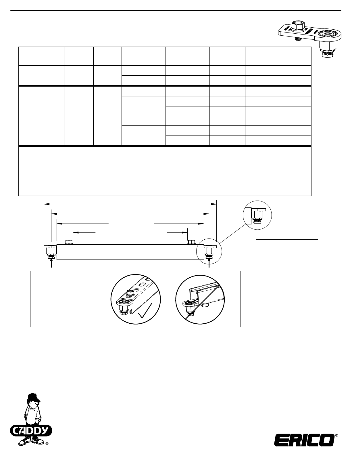
CADDY® ROD LOCK Strut End Bracket
3/8", M8, M10
Part Number
CRLSEB37EG
Article
Number
N/A
Rod Size
3/8"
Strut Channel
Profile
Strut Channel
Thi ckness
Maximum
Load
Length Factor (Lf) for
Maximum Load
A Type 12 Ga 1,000 lbs 8 inches
C Type 14 Ga 460 lbs 2 inches
A Type 2.5 mm 4,448 N 200 mm
CRLSEBM8EG 390026
M8
C Type
2.0 mm 2,046 N 50 mm
1.5 mm 1,619 N 50 mm
A Type 2.5 mm 4,448 N 200 mm
CRLSEBM10EG 390027
M10
C Type
2.0 mm 2,046 N 50 mm
1.5 mm 1,619 N 50 mm
Notes:
Loads listed are uniformly distributed with a pair of CADDY ROD LOCK Strut End Brackets. Brackets are designed to be used as a pair and not 1.
in single bracket applications
When deflection is not a factor, use a stress of 25,000 psi [172.4 MPa]2.
The CADDY® ERISTRUT load tables, a "Uniform Load at Stress" for imperial strut or "Loading Case B from Allowable Tension" for metric strut, 3.
should be used to determine the capacity ratings for a Beam Span = Strut Length "L" + Length Factor "Lf "
When deflection is a factor, use a deflection of span/240 for imperial strut or use a deflection of span/200 for metric strut4.
The CADDY ERISTRUT load tables, a "Uniform Load when Maximum Deflection = span/240" for imperial strut or "Loading Case B from Allowable 5.
Deflection" for metric strut, should be used to determine the capacity ratings for a Beam Span = Strut Length "L" + Length Factor "Lf "
The load value selected per Notes 3 and 5 includes a half slot hole factor of 0.926.
It is recommended that a factor of safety, appropriate for the application of the CADDY ROD LOCK Strut End Brackets and strut assembly, be 7.
applied to the capactiy rating (found in Notes 3 and 5) to determine a safe working load
Overall Length "L2"
Span "L1" between two rods
Strut Length "L"
Strut Working Space "L3"
Length Calculations:
See Sheet 2
for installation
1/2 F 1/2 F
Warning:
Product must be installed
with the open side of the
channel facing down.
WARNING:
ERICO products shall be installed and used only as indicated in ERICO product instruction sheets and training materials. Instruction sheets are available at 1.
www.erico.com and from your ERICO customer service representative.
ERICO products must never be used for a purpose other than the purpose for which they were designed or in a manner that exceeds specified load ratings.2.
All instructions must be completely
Improper installation, misuse, misapplication or other failure to completely follow ERICO's instructions and warnings may cause product malfunction, property 4.
damage, serious bodily injury and death.
Products that are manufactured using spring steel components shall be used only in a non-corrosive indoor environment. 5.
All pipe supports, hangers, intermediate components and structural attachments must ONLY be used as described herein and are NEVER to be used for any 6.
other purpose.
NOTE: All load ratings are for static conditions and do not account for dynamic loading such as wind, water or seismic loads, unless otherwise noted.
The customer is responsible for:
a. Conformance to all governing codes.
b. The integrity of structures to which the products are attached, including their capability of safely accepting the loads imposed, as evaluated by a qualified
engineer.
c. Using appropriate industry standard hardware as noted above.
SAFETY INSTRUCTIONS:
All governing codes and regulations and those required by the job site must be observed.
Always use appropriate safety equipment such as eye protection, hard hat, and gloves as appropriate to the application.
followed to ensure proper and safe installation and performance. 3.
1. Span "L1" between two rods:
L1 max = Strut Length "L" +
2.52" [64mm]
L1 min = Strut Length "L" +
1.14" [29mm]
2. Overall Length "L2":
L2 max = L1 max + 1.62" [41mm]
L2 min = L1 min + 1.62" [41mm]
3. Strut Working Space "L3":
L3 max = Strut Length "L" -
2.1" [54mm]
L3 min = Strut Length "L" -
3.5" [88mm]
CADDY, CADWELD, CRITEC, ERICO, ERIFLEX, ERITECH, and LENTON are registered trademarks of ERICO International Corporation.
TECHNICAL SUPPORT:
www.erico.com
CFS491_A
1 OF 2
© 2014 ERICO International Corporation.
Page 2
INSTRUCTION SHEET
CADDY® ROD LOCK Strut End Bracket
3/8", M8, M10
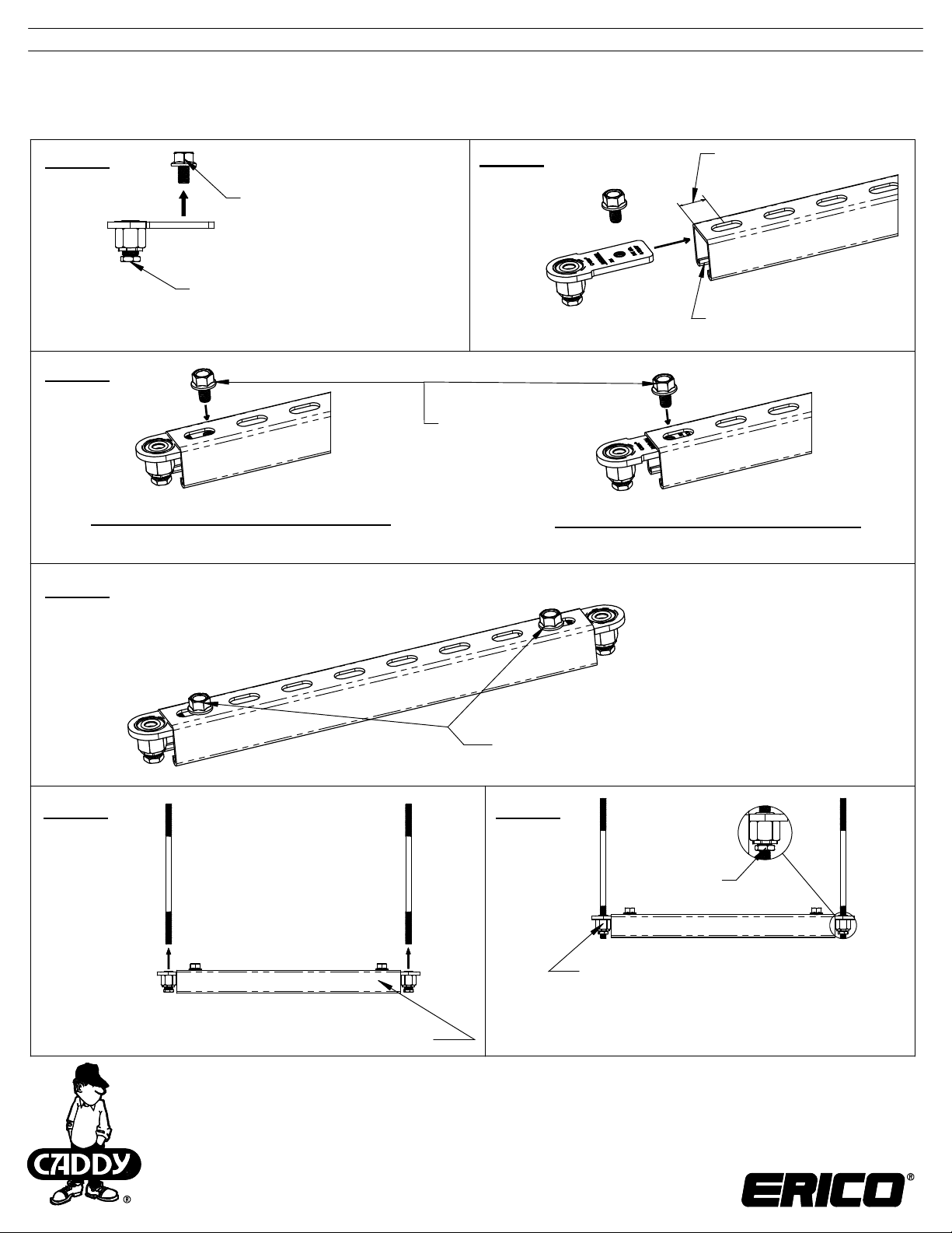
Step 1
Untighten the flanged screw
Rotate lock nut
counter clockwise
until reaches the fully
extended position.
Step 3
Assembly at minimum open position
Step 4
Step 2
Tighten
the flanged screw
by hand
Assembly at maximum open position
1" [25mm] minimum
required at both ends
Open side of strut must
be facing down
Step 5
Push CADDY ROD LOCK to engage threaded rods
CADDY, CADWELD, CRITEC, ERICO, ERIFLEX, ERITECH, and LENTON are registered trademarks of ERICO International Corporation.
TECHNICAL SUPPORT:
www.erico.com
CFS491_A
2 OF 2
Tighten with 60 in-lbs [7 N-m] torque
using 11/16" or 17mm wrench
Step 6
Step 6-1:
Tighten
lock nut on
both sides
Step 6-2:
Rotate the hex housing to finely
tune the strut height.
Clockwise = adjust assembly down
Counter-clockwise = adjust assembly up
© 2014 ERICO International Corporation.
 Loading...