

INSTRUCTION SHEET
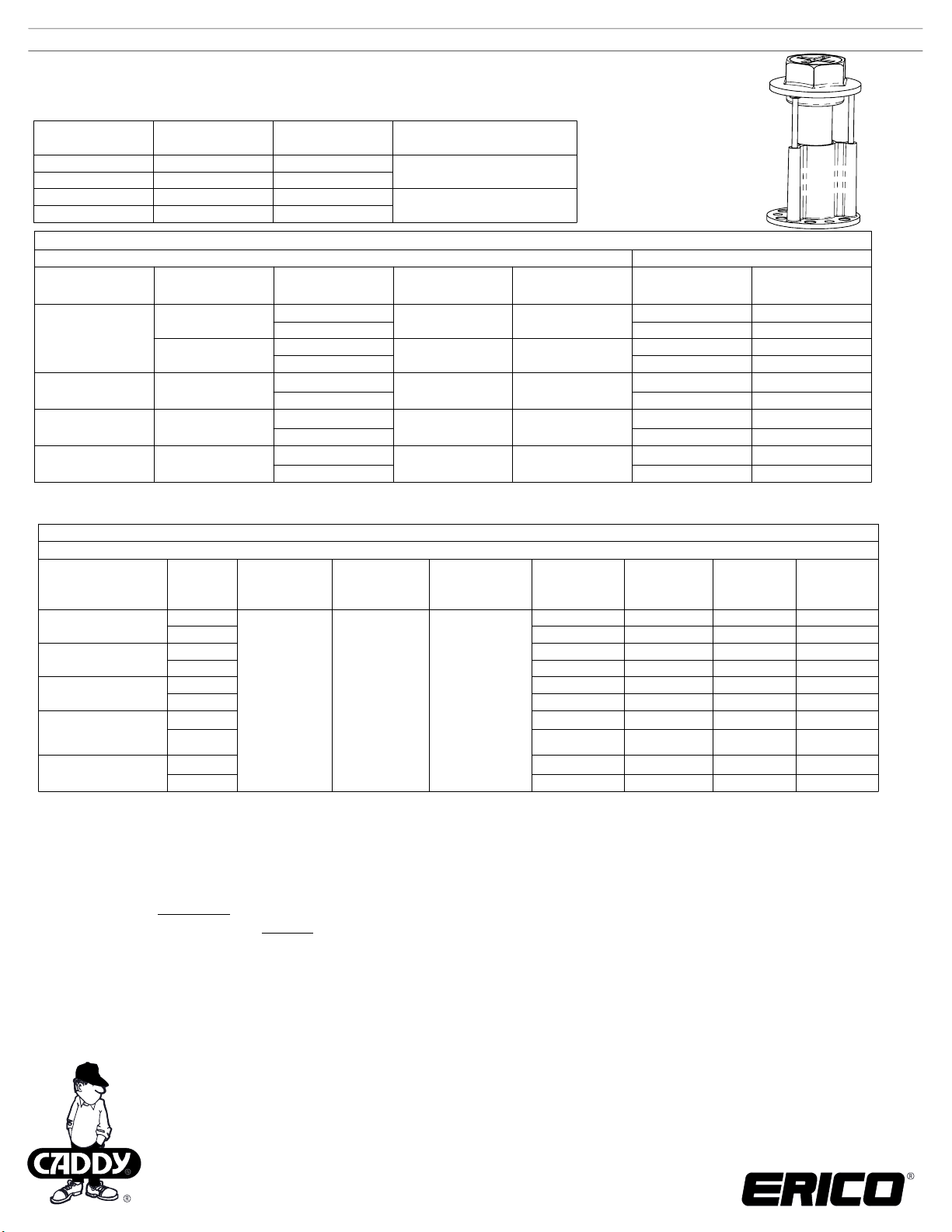
CADDY® ROD LOCK Plywood Pre-set Anchor
3/8 inch, 1/2 inch, M10 and M12
Part Number
CRLW37EG
CRLWM10EG
CRLW50EG
CRLWM12EG
Article Number
N/A
390019
N/A
390020
Rod Size
3/8"
M10
1/2"
M12
Max. FM® 1951 pipe size
4" or DN100
8" or DN200
Allowable Tension & Shear Loads for Threaded Rod*
Threaded rod itself
Steel Type
Standard Carbon
Steel Rod
High Strength
Carbon Steel Rod
Stainless Steel Rod
(SS304/ SS316)
Europe Steel Rod
ASTM®/ISO® Steel
designation
A307, Grade C
A36
A193, Grade B7
A193, Grade
B8/B8M, Class 1
ISO 898-1,
Class 4.6
Threaded rod size
3/8"
1/2"
3/8"
1/2"
3/8"
1/2"
3/8"
1/2"
M10
M12
Minimum Yield
strength
Minimum Tensile
strength
36.0 ksi
36.0 ksi
105.0 ksi 120.0 ksi
30.0 ksi 75.0 ksi
240 MPa 400 MPa
58.0 ksi
58.0 ksi
Allowable Tension
Load
Lbs [kN]
2,115 [9.5] 1,090 [4.9]
3,755 [16.9]
2,115 [9.5] 1,090 [4.9]
3,755 [16.9]
4,375 [19.7] 2,255 [10.1]
7,775 [35.0] 4,050 [18.2]
2,720 [12.1]
4,850 [21.6] 2,500 [11.1]
2,350 [10.5]
3,390 [15.1]
Allowable Shear
Load
Lbs [kN]
1,940 [8.7]
1,940 [8.7]
1,400 [6.2]
1,210 [5.4]
1,745 [7.8]
* Do not use a hot dip galvanized threaded rod.
* For in-door applications only.
Product Allowable Tension & Shear Loads with Normal-Weight Concrete (See Notes 1, 2, 3, 4 & 5)
Normal-Weight Concrete having 3,000 psi [20.7 Mpa] minimum compression strength
Threaded Rod Steel
Type
A307, Grade C
A36
A193, Grade B7
A193, Grade
B8/B8M, Class 1
(SS304/ SS316)
Europe ISO Class 4.6
Threaded
rod size
3/8"
1/2"
3/8"
1/2"
3/8"
1/2"
3/8"
1/2"
M10
M12
Minimum
Concrete slab
Thickness
Inch [mm]
3-1/4" [83mm]
Minimum Edge
Distance Inch
[mm]
Minimum
Spacing
Inch [mm]
6" [152mm] 8" [203mm]
Ultimate
Tension Load
Lbs [kN]
Ultimate
Shear Load
Lbs [kN]
4,220 [18.8] 3,270 [14.6]
4,820 [21.7] 5,820 [25.9]
4,220 [18.8] 3,270 [14.6]
4,820 [21.7] 5,820 [25.9]
4,220 [18.8] 5,330 [24.0]
4,820 [21.7] 7,400 [33.3]
4,220 [18.8] 4,210 [18.7]
4,820 [21.7] 7,400 [33.3]
4,220 [18.8] 3,630 [16.2]
4,820 [21.7] 5,235 [23.3]
Allowable
Tension Load
Lbs [kN]
Allowable
Shear Load
Lbs [kN]
1,407 [6.3] 1,090 [4.9]
1,605 [7.2]
1,940[8.7]
1,407 [6.3] 1,090 [4.9]
1,605 [7.2]
1,940[8.7]
1,407 [6.3] 1,775 [8.0]
1,605 [7.2]
2,465 [11.1]
1,407 [6.3] 1,405 [6.2]
1,605 [7.2]
2,465 [11.1]
1,407 [6.3] 1,210 [5.4]
1,605 [7.2] 1,745 [7.8]
Notes:
1. Allowable tension & shear load capacities are calculated using an applied safety factor of 3.0
2. Allowable working load must be the lesser of product allowable tension & shear loads showing above table.
3. NFPA® 13 design requirements are 5 times the weight of the water filled pipe plus 250 lbs.
4. MSS requires the safety factor of 3.5
5. Allowable loads for anchors to resist short term loads such as earthquake or wind may be increased by 33.33% for the duration of the
load where permitted by code.
WARNING:
ERICO products shall be installed and used only as indicated in ERICO product instruction sheets and training materials. Instruction sheets are available at
1.
www.erico.com
ERICO products must never be used for a purpose other than the purpose for which they were designed or in a manner that exceeds specified load ratings.
2.
All instructions must be
3.
Improper installation, misuse, misapplication or other failure to completely follow ERICO's instructions and warnings may cause product malfunction, property
4.
damage, serious bodily injury and death.
Products that are manufactured using spring steel components shall be used only in a non-corrosive indoor environment.
5.
All pipe supports, hangers, intermediate components and structural attachments must ONLY be used as described herein and are NEVER to be used for any
6.
other purpose.
NOTE: All load ratings are for static conditions and do not account for dynamic loading such as wind, water or seismic loads, unless otherwise noted.
The customer is responsible for:
a. Conformance to all governing codes.
b. The integrity of structures to which the products are attached, including their capability of safely accepting the loads imposed, as evaluated by a qualified
engineer.
c. Using appropriate industry standard hardware as noted above.
SAFETY INSTRUCTIONS:
All governing codes and regulations and those required by the job site must be observed.
Always use appropriate safety equipment such as eye protection, hard hat, and gloves as appropriate to the application.
ASTM is a registered trademark of American Society for Testing and Materials
FM is a registered certification mark of FM Approvals LLC, LTD
ISO is a registered trademark of International Organization for Standardization
NFPA is a registered trademark of National Fire Protection Association, Inc.
CADDY, CADWELD, CRITEC, ERICO, ERIFLEX, ERITECH, and LENTON are registered trademarks of ERICO International Corporation.
and from your ERICO customer service representative.
completely
followed to ensure proper and safe installation and performance.
TECHNICAL SUPPORT:
www.erico.com
CFS479_C
1 OF 2
© 2013, 2014 ERICO International
Corporation.
INSTRUCTION SHEET
Product Allowable Tension & Shear Loads with Light-Weight Concrete (See Notes 1, 2, 3, 4 & 5)
Threaded Rod
Steel Type
A307, Grade C
A36
A193, Grade B7
B193, Grade
B8/B8M, Class 1
(SS304/ SS316)
Europe ISO
Class 4.6
Notes
:
1.
2.
3.
4.
5.
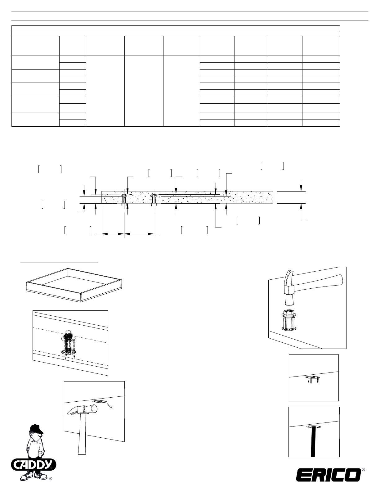
2.2in
55mm
Threaded
Allowable tension & shear load capacities are calculated using an applied safety factor of 3.0
Allowable working load must be the lesser of product allowable tension & shear loads showing above table.
NFPA® 13 design requirements are 5 times the weight of the water filled pipe plus 250 lbs.
MSS requires the safety factor of 3.5
Allowable loads for anchors to resist short term loads such as earthquake or wind may be increased by 33.33% for the duration
of the load where permitted by code.
required
threaded rod depth
for 3/8in & M10
Light-Weight Concrete having 3,000 psi [20.7 Mpa] minimum compression strength
rod size
3/8"
1/2"
3/8"
1/2"
3/8"
1/2"
3/8"
1/2"
M10
M12
Minimum
Concrete slab
Thickness
Inch [mm]
3 1/4" [ 83mm]
Minimum Edge
Distance
Inch [mm]
6" [152mm] 8" [203mm]
2.4in
61mm
Minimum
Spacing
Inch [mm]
3/8in & M10
Ultimate
Tension Load
Lbs [kN]
3,710 [16.5] 3,270 [14.6]
4,270 [19.2] 5,820 [25.9]
3,710 [16.5] 3,270 [14.6]
4,270 [19.2] 5,820 [25.9]
3,710 [16.5] 5,280 [23.8]
4,270 [19.2] 7,180 [32.3]
3,710 [16.5] 4,210 [18.7]
4,270 [19.2] 7,180 [32.3]
3,710 [16.5] 3,630 [16.2]
4,270 [19.2] 5,235 [23.3]
2.3in
63mm
1/2in & M12
Ultimate
Shear Load
depth for 1/2in & M12
Allowable
Lbs [kN]
1.9in
Tension Load
Lbs [kN]
1237 [5.5]
1,425 [6.4]
1,237 [5.5] 1,090 [4.9]
1,425 [6.4]
1,237 [5.5] 1,760 [7.9]
1,425 [6.4]
1,237 [5.5] 1,405 [6.2]
1,425 [6.4]
1,237 [5.5] 1,210 [5.4]
1,425 [6.4] 1,745 [7.8]
48mm
Concrete cone
Allowable
Shear Load
Lbs [kN]
1,090 [4.9]
1,940[8.7]
1,940[8.7]
2,395 [10.8]
2,395 [10.8]
1.9in
48mm
Concrete cone
depth for 3/8" & M10
6.0in
152mm
Edge to Center
Assembly Instructions
3-1/4in [83mm]Min.
Concrete Thickness
8.0in
203mm
Between Centers
2.3in
58mm
required
threaded rod depth
for 1/2in and M12
:
Step 1 - Construct the necessary wood form.
Step 2 - Assemble anchor to
wood form using a hammer.
Step 3 - Pour concrete into wood form.
Step 4 - After concrete is cured,
remove wood form.
Step 5 - Remove protruding nails
by shearing off with a hammer.
Step 6 -Push-in threaded rod.
CADDY, CADWELD, CRITEC, ERICO, ERIFLEX, ERITECH, and LENTON are registered trademarks of ERICO International Corporation.
TECHNICAL SUPPORT:
www.erico.com
CFS479_C
2 OF 2
© 2013, 2014 ERICO International
Corporation.
 Loading...