

Page 1
Refer to the mold tag for applicable instruction sheets. IPRSJ_C
CADWELD® Rail Joint Head Bonds
IPRSJ_C
WARNING: The area where the bond is to be
I. HOW TO READ THESE INSTRUCTIONS /
WHAT THE SYMBOLS MEAN
The purpose of safety symbols is to attract your
attention to possible dangers. The safety symbols,
and the explanations with them, deserve your careful
attention and understanding. The safety warnings do
not by themselves eliminate any danger. The instructions
and warnings are not substitutes for proper accident
prevention measures.
SAFETY ALERT SYMBOL: Indicates warning or caution. It may
!
be used in conjunction with other symbols or pictographs.
WARNING: Failure to obey a safety warning may result in
!
property damage, serious personal injury or death, and the
serious personal injury or death of others. Always follow the
safety precautions to reduce these risks.
CAUTION: Failure to obey a safety caution may result in property
!
damage, personal injury, and injury to others. Always follow
the safety precautions to reduce the risk of fi re, other property
damage and personal injury.
NOTE: Advises you of information or instructions vital to the
operation or maintenance of the equipment.
In the following instructions, cautions and warnings, there are
two types of consequences for failure to heed:
A. IMMEDIATE, that may result in personal injury or a failed
operation that may result in a less than optimum bond and that
will not give the physical and electrical performance expected.
!
applied must be sheltered suffi ciently if the weather is
inclement. This is to keep the rail surface, all equipment, and
materials dry until the weld is completed. Failure to do so may
result in an unsafe application with the risk of personal injury
and a less than optimum bond.
CAUTION: The work area must be well ventilated.
!
Workers should avoid breathing the smoke of the exothermic
reaction by positioning themselves upwind of the mold before
igniting the welding material. After ignition, it is advisable to
step back from the mold. Failure to observe this instruction
may result in lung irritation.
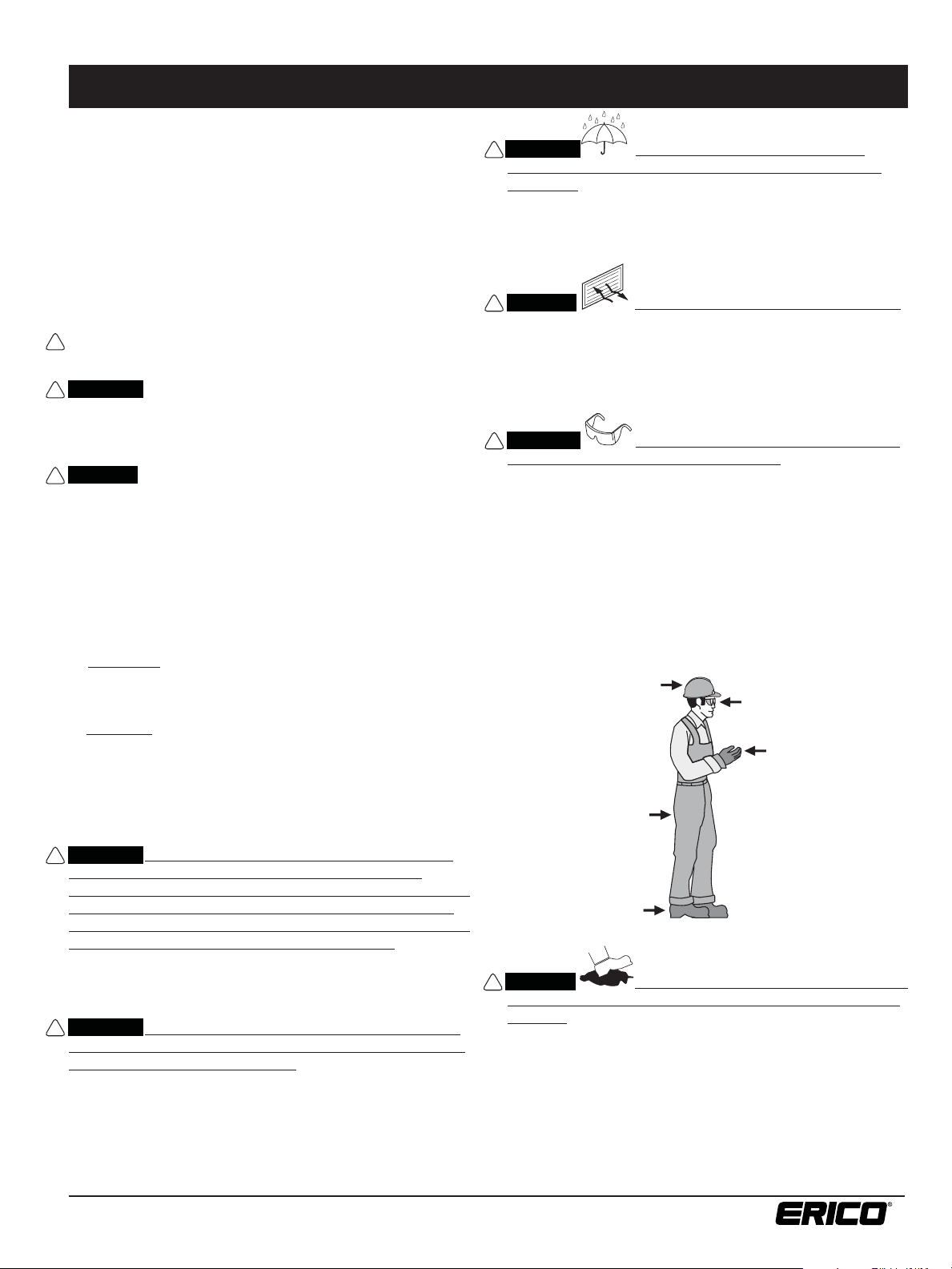
WARNING: The worker(s) performing the welding
!
must be properly dressed and equipped. Examples include
cotton or woolen garments (most synthetic fabrics melt rather
than char when exposed to fl ame, causing severe burns), safety
footwear with non-slip soles, head protection, leather gloves,
eye goggles and other clothing and equipment recommended
or required by the person’s employer, industry practice, or
applicable laws and regulations. The worker(s) must not be
under the infl uence of any alcohol, drugs or other chemicals
that would impair their judgment or performance of the job.
Failure to observe this may result in serious personal injury.
See Figure 1.
Safety Helmet
Safety Goggles
B. EVENTUAL, that may result in a later premature rail break,
causing a serious derailment accident with personal injuries
or death, and loss of property.
II. GENERAL RULES FOR SAFETY IN THE APPLICATION
OF EXOTHERMIC HEAD BONDS TO THE RAIL
WARNING: Do not attempt to make an exothermic bond
!
until you have thoroughly read and understand the
instructions that accompany all of the various components
of the system and have been properly trained in the use
of this product. Use only the system components designed
to be used together from a single manufacturer. Failure to
comply may result in unsatisfactory bonding as well as accidents
involving fi re, personal injury, and rail damage that may lead to
property damage, injury or death.
WARNING: Only the correct grinding equipment, welding
!
equipment, welding material, and bonds designed for the
specifi c application must be used. All items used must be
designed and supplied by the same manufacturer. All items must
be in good condition and not worn, altered or damaged. Failure
to do so may result in an unsafe application with the risk of
personal injury and/or a less than optimum bond.
Cuffed Leather
FIGURE
1
Jacket or Shirt
and Trousers
Safety Shoes
CAUTION: The worker(s) must be certain that they
!
can achieve good footing in the area where the weld will
be done. They should be able to step away from the weld
reaction, to be upwind of it. Failure to observe this may result
in personal injury.
Gloves
www.erico.com
1
Page 2
Refer to the mold tag for applicable instruction sheets. IPRSJ_C
CADWELD® Rail Joint Head Bonds
WARNING: Carefully following the instructions
!
for exothermic bonding is very important to achieving
a quality reliable bond. Failure to do so may cause hidden
potential problems, the least of which is a poor electrical
connection, and the most serious of which is an eventual
broken rail leading to property damage, injury or death to
the installer and others.
III. PREPARATION
WARNING: Protect against potential fi re hazards
!
local to the bonding area and remove all fl ammable
materials from the work area. Notify in advance other
workers in the immediate area that a welding procedure
is about to be done. Failure to do this increases the risk of
fi re with the possibility of property damage, personal injury
and death.
NOTE: In case of a fi re involving large quantities of exothermic
welding material, CO
a distance are required to reduce the spread of the fi re.
WARNING: The location of the bond is very important!
!
The intent of a rail head bond is to electrically join two rail
sections. Rail head bonds must be done only within the confi nes
of the joint/splice bar as near to the bar center as practical.
Failure to observe this may result in a rail break leading to
property damage, injury or death to others. See Figure 2.
2
or large quantities of water applied from
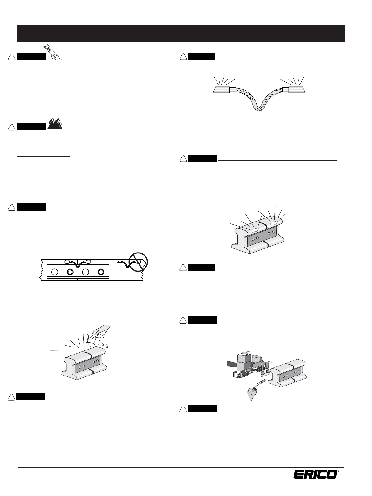
CAUTION: The bond terminals must have a bright surface.
!
Failure to comply with this may result in a less than optimal weld.
See Figure 4.
FIGURE
4
3.
Lightly grind the rail surface using an ERICO® approved grinding
wheel that is self-cleaning or a CADWELD
Cleaner. Grinding wheels with resin binders may leave a surface
fi lm that may contaminate the surface, interfering with the
achievement of an optimum bond and causing weld porosity.
WARNING: The area of the rail head to be bonded must
!
be lightly ground to a bright fi nish with no visible scratch
marks or gouges (normal uniform fi nishing marks are
acceptable). Failure to observe this may result in visible
scratches or gouges due to overly aggressive grinding that are
potential crack initiators and that may lead to rail breaks causing
derailment accidents with property damage, injury and death to
others. See Figure 5.
FIGURE
5
®
T-34 Rail Head
FIGURE
2
1. Clean the rail surface and bond terminals. Scrape off excess
dirt and grease, and wipe away any remaining residue using
a clean rag saturated with a railroad approved solvent.
See Figure 3. The rail must be dry prior to welding!
FIGURE
3
WARNING: The area of the rail where the bond will be
!
applied and the bond terminals must be clean and dry.
Failure to comply can cause poor bonding, excessive weld
porosity, and/or spewing molten welding material with the
potential for serious burns to the worker.
2. Use abrasive cloth or wire brush on the bond terminals if
needed to remove surface oxidation.
CAUTION: Grinding must not be done more than 4 hours
!
prior to bonding. If the time lapse is longer, suffi cient
contaminating rust may re-form requiring additional grinding.
Failure to observe this may result in a less than optimum bond.
4. Dry the mold and rail by heating them to about 250°F (120°C)
with a small propane torch.
WARNING: The rail and mold must both be warmed to
!
drive off moisture. Failure to observe this may result in weld
spatter with the potential for serious burn injury, and a less than
optimum bond with excessive porosity. See Figure 6.
FIGURE
6
WARNING: Rebonding over the application of an earlier
!
bond is only permissible in areas of minimal stress such as
the head of the rail within the confi nes of the joint/splice
bar! Remove the original bond by grinding down to a smooth
layer of parent rail steel.The new bond can then be made in the
same location as the previous bond.Failure to observe this may
result in a rail break leading to property damage, injury or death
to others.
www.erico.com
2
Page 3

Refer to the mold tag for applicable instruction sheets. IPRSJ_C
CADWELD® Rail Joint Head Bonds
IV. WELDING PROCEDURE
1. Place bond in welder with fl at surface against rail head and
end of terminal against bond clip. This correctly positions
bond in weld cavity. Be sure the bond clip is in good condition
and properly positions terminal under center of tap hole as
shown. See Figure 7.
Tap Hole
Bond
FIGURE
7
Bond Clip
Terminal
2. Position the welder with attached molds on the rail head.
The bottom edge of the mold should be aligned with the
lower edge of the rail head. Use the mold height adjusting
screws to properly align the mold. See Figure 8.
3. Close clamp to lock welder on rail. Clamp is adjustable for
rail sizes. Check that mold face fi ts against rail and bond
terminal is held against rail by clevis. See Figure 8.
Clamp Adjustment Screw
in excess of 4000°F, therefore great care must be exercised
to avoid spillage of the molten metal. Failure to observe this
warning may result in molten metal leakage onto the rail
with immediate risk of personal injury, and potentially serious
structural damage to the rail that could result in a rail break
leading to property damage, injury or death to others.
FIGURE
9
4. Insert one steel disk, dished (concave) side up, in the crucible
to cover the taphole. See Figure 10.
Mold Height Adjusting Screw
Graphite Cover
Starting Material
FIGURE
8
WARNING: Correctly positioning the mold against the rail
!
with the welder device is critical for safety and success in
making a bond. There must be no cracks between the lower
part of the mold that contains the weld cavity and the rail
surface; if a crack is present, the mold should be discarded and
a new one used. See Figure 9. (Molds can generally be used for
up to 50 welds.) The exothermic reaction reaches a temperature
Welding Material
Disk
Bond Clip
Splice Bar
FIGURE
10
CAUTION: The steel disc must be correctly installed into
!
the mold crucible. Failure to properly position it may result
in premature leakage into the mold area, resulting in an
unacceptable weld. See Figure 11.
FIGURE
11
5. Dump the contents of the welding material container into
the crucible, being careful not to upset the disk.
Starting Material
Welding Material
Disk
www.erico.com
3
Page 4

Refer to the mold tag for applicable instruction sheets. IPRSJ_C
CADWELD® Rail Joint Head Bonds
CAUTION: Install only the specifi ed welding material in
!
the mold crucible. Use only the welding material size that is
specifi ed on the mold. ERICO
is formulated specifi cally for use with rail steel; it is packaged in
a blue tube with a yellow cap. Dump all of the welding material
into the crucible, then carefully tap the tube on a hard surface
to loosen the starting material from the bottom of the tube and
distribute half on top of the welding material, close the mold
cover, and pour the remainder in the opening of the mold cover.
See Figures 10 and 12. Failure to comply may result in diffi culty
getting the reaction started and/or an unacceptable weld.
FIGURE
12
®
brand of welding material (F80)
Starting Material
Crucible Cover
Changing Molds (See Figure 13.)
A. Remove mold back frame Screw “A”.
B. Pull out worn mold.
C. Insert new mold, replace Screw “A”. Check bolt “B” to be
sure it is not too tight. Mold must be free to move within
frame against pressure spring.
Pull Out Worn Mold
FIGURE
13
Bolt “B”
Screw “A”
CAUTION: Avoid direct eye contact with the “fl ash” of
!
light from the ignition of the starting material.
6. Position yourself upwind of the molds, place the tip of the
fl int ignitor at the cover opening and ignite. Remove the
igniter quickly to prevent fouling. If igniting two molds in
sequence, ignite the downwind mold fi rst.
CAUTION: Allow 15 seconds for mold cooling after the
!
reaction. This will permit the molten metal to solidify.
7. Carefully open the mold cover and break up the slag in the
crucible using the blade of the mold cleaning tool.
8. Unlock clamp and remove welder by pulling the mold straight
back from the rail. Failure to observe this may result in mold
damage and its premature scrapping. Molds can generally be
re-used up to 50 times.
9. Dump the slag from the crucible and remove the slag from
the taphole using the curved end of the mold cleaner. Dump
slag in the ballast, not onto the ties.
10.
Check the molds for breakage or residual slag before
proceeding with the next weld.
Note: If you have any questions or require further instructions,
or would like training, contact ERICO at 1-800-447-7245.
Copyright ©2008, 2010, 2012, 2013 ERICO International Corporation. All rights reserved.
CADDY, CADWELD, CRITEC, ERICO, ERIFLEX, ERITECH, and LENTON are registered trademarks of ERICO International Corporation.
www.erico.com
4
IPRSJ_C R1121IS10WWEN PUR1013
 Loading...