

Page 1
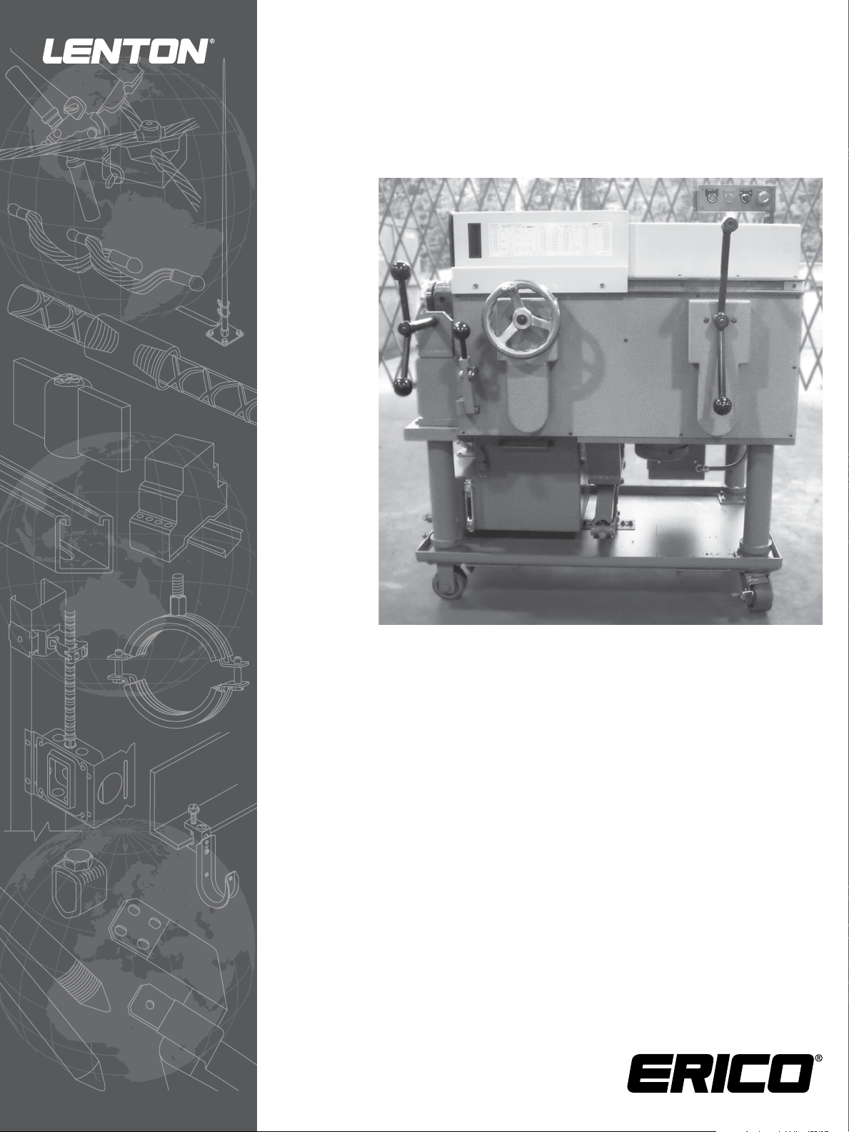
Mid-Range Bar Threader
Instruction Manual
Page 2

Table of Contents
Uncrating the Machine ....................................................... 3 – 4
Electrical ..................................................................................... 5
Center Rings ........................................................................ 6 – 7
Add Oil ....................................................................................... 8
Change Control Key .......................................................... 9 – 10
Change Chasers and Holders .......................................... 11 – 15
Change Control Block .................................................... 16 – 18
Threading Operation ...................................................... 19 – 20
Checking Threads and Bar End Engagement ...................... 21
Maintenance ........................................................................... 22
Troubleshooting ..................................................................... 23
Operator Reference Chart ..................................................... 23
WARNING
1. ERICO products shall be installed and used only as indicated in ERICO
product instruction sheets and training materials. Instruction sheets
are available at www.erico.com and from your ERICO customer
service representative.
2. ERICO products must never be used for a purpose other than the
purpose for which they were designed or in a manner that exceeds
specified load ratings.
3. All instructions must be completely followed to ensure proper and
safe installation and performance.
4. Improper installation, misuse, misapplication or other failure to
completely follow ERICO’s instructions and warnings may cause
product malfunction, property damage, serious bodily injury and death.
The customer is responsible for:
a. Conformance to all governing codes.
b. The integrity of structures to which the products are attached,
including their capability of safely accepting the loads imposed,
as evaluated by a qualified engineer.
c. Using appropriate industry standard hardware as noted above.
SAFETY INSTRUCTIONS:
All governing codes and regulations and those required by the job site
must be observed. Always use appropriate safety equipment such as
eye protection, hard hat, and gloves as appropriate to the application.
2
www.erico.com
Page 3
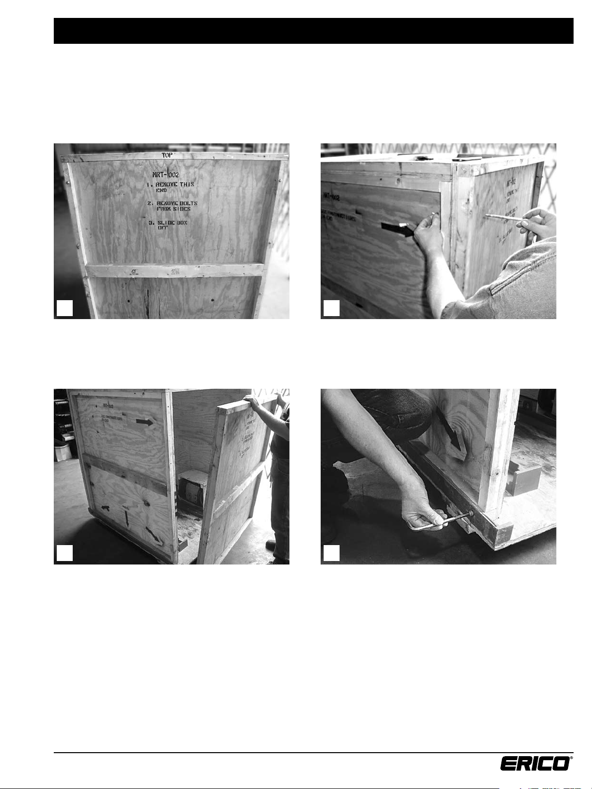
Uncrating the Machine
When uncrating the machine please follow these steps.
If you have any questions please call ERICO Inc. at 1 (800) 822-7975.
21
Locate the front door panel. Loosen the eight bolts and wing-nuts securing the door.
43
Remove the front door. Remove the three bolts from the bottom of each side.
www.erico.com
3
Page 4
Uncrating the Machine
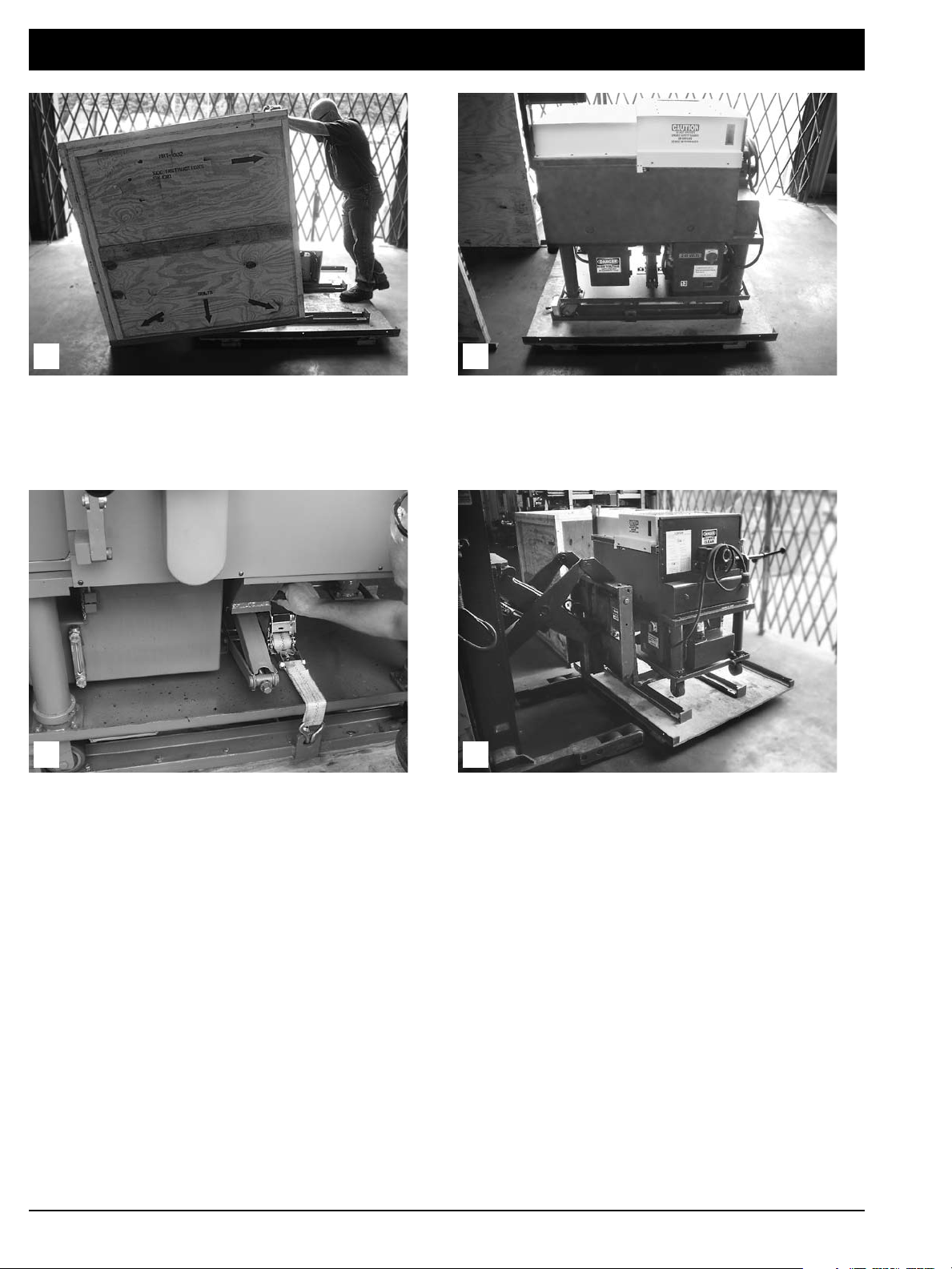
5
Slide the top off the base Machine on crate base
6
7 8
Remove the tie-down to lift machine from base The machine can now be lifted off the base
4
www.erico.com
Page 5
Electrical
21
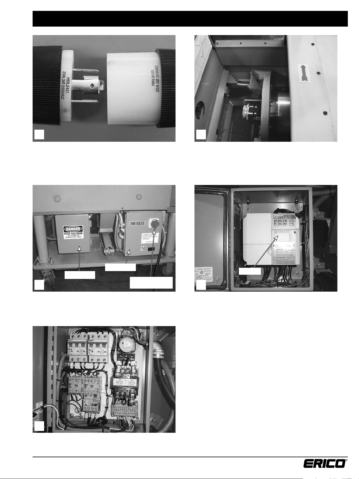
The Mid-Range Bar Threader requires 220-240 volt,
3 phase power. A four-pronged locking plug as shown
is standard.
Power Panel
Inverter Box
Main Power
Disconnect Switch
View of Inverter Box and Power Panel. The Red Knob
located on the Power Panel is the main power
disconnect switch.
After connecting the power be sure the head of the bar
threader is rotating in the direction indicated by the red
arrow on the hood. If it is not rotating in the correct
direction, switch any two of the power leads in the plug.
Inverter
43
View of inside the Inverter Box. The Inverter controls the
high and low speed on the DC Motor.
5
View of inside the Power Panel.
www.erico.com
5
Page 6
Center Rings
21
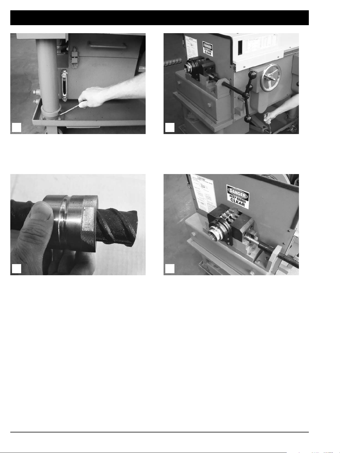
Before adjusting the table height, you must first loosen
each collar located at the bottom of each table leg.
To obtain the best centering of the rebar into the
threading machine, the best fitting set of center rings
should be used. We offer two or three different size sets
per bar. To make sure you are using the correct set, slide
one of the center rings per set over the bar ends to be
threaded to determine which one slides on easily with
the least amount of slop. Each center ring is stamped
with the bar size it is to be used with in millimeters.
Adjust the table height with a ½” square drive ratchet
using a ¾” standard drive socket.
43
The bar threader will come to you set up to run the largest
bar size you will be threading.
6
www.erico.com
Page 7
Center Rings
65
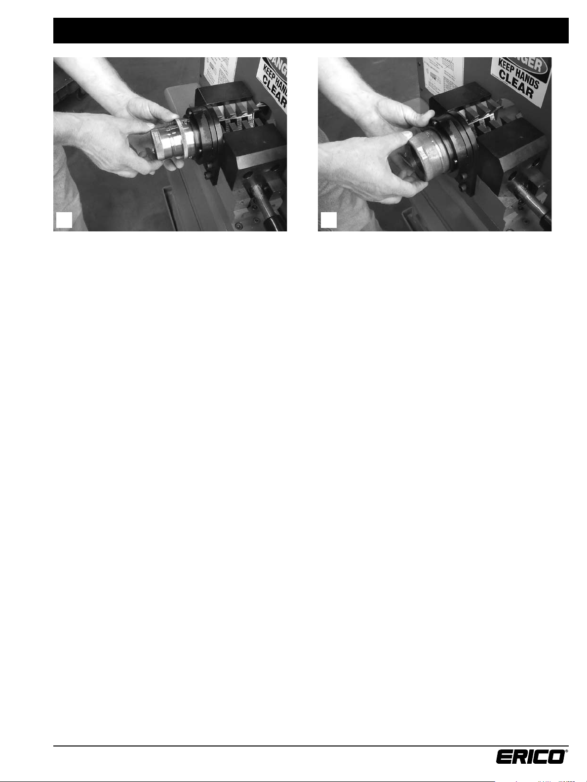
To change centers to a different bar size or to go with a
set that fits the bar better, push in the release ring and
pull out the existing center. Put in the new center and
lock it in place by letting loose of the release ring.
When threading a #14 or #18 bar, the adaptor ring must
be removed. This is done in the same way you remove the
center ring as in the previous step.
www.erico.com
7
Page 8
Add Oil
21
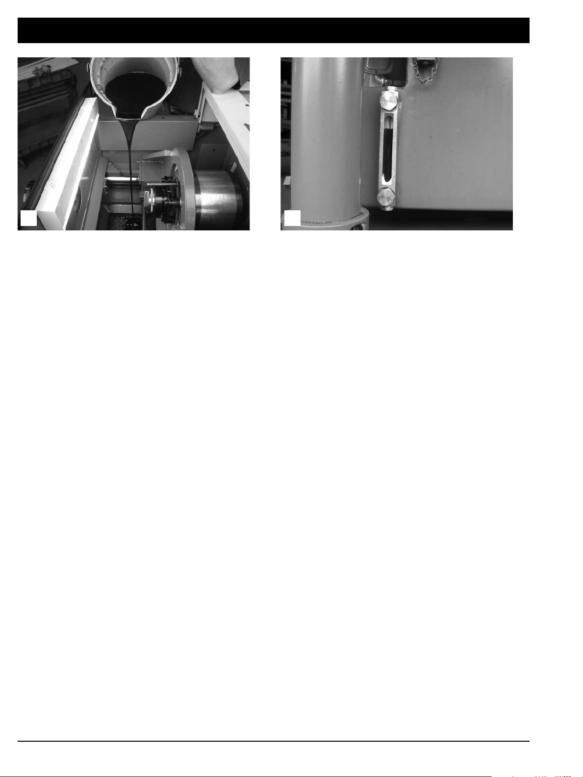
Prior to threading, the oil must be added. Pour the oil
onto the chip funnel and it will flow into the oil reservoir.
Only part # ELOIL should be used.
The reservoir is properly filled when the oil level is at the
top of the sight glass.
8
www.erico.com
Page 9

Change Control Key
1A 1B
Remove the cover plate bolts. Three bolts hold it in place.
32
Remove the holders from the head of the bar threader. To change the key, remove the screw, compression spring,
and the support rod from the head.
54
To remove the control block loosen the support rod
bushing and pull out the support rod and spring.
This will free the control block to fall down.
Loosen the front bearing and remove the rear bearing.
www.erico.com
9
Page 10

Change Control Key
76
Slide the key out. Each key is stamped on the front with
the metric bar size.
8 9
Before tightening the threaded bushing down make sure
that carriage is all the way back to the right.
Slide in the new key and replace and tighten both the
front and rear bearings.
While holding the feed handle back move your control ring
handle forward into step drum position number three.
10 11
When installing the new control block in the cutting square
replace the support rod, spring, and screw. The support rod
goes through the hole in the control block and engages in
a hole on the other side of the cutting square.
You should always tighten your threaded bushing down
until the spring is fully compressed then back off half of
a turn.
10
www.erico.com
Page 11

Change Chasers and Holders
1A 1B
Remove the face plate bolts. Three bolts hold it in place.
32
Remove the holders from the head of the bar threader. Loosen the set screw as shown above.
4A 4B
Slide the chaser out of the holder. Chasers and holders have matching numbers.
The number 1 chaser goes into the number 1 holder, etc.
www.erico.com
11
Page 12

Change Chasers and Holders
65
Before installing the chaser make sure the woodruff key
is tight. Press on both ends of the woodruff key with an
allen wrench, it should not move.
7
Take the hold down pin (ELMP203PIN) and place it through
the hole of the chaser as shown above.
To replace a woodruff key, set the key into the slot by
hand and drive into position using a hammer and punch.
8A
Insert the chaser pin into the top hole of the holder and
push down making sure that the woodruff slot aligns with
the woodruff key until the chaser sits completely flush on
the holder shelf.
8B
This is what a chaser looks like when it is installed correctly
onto the holder.
9
After the chaser is installed correctly on the holder, hold
the chaser in place while tightening down the set screw
against the hold down pin.
12
www.erico.com
Page 13

Change Chasers and Holders
10A 10B
Before replacing the holders make sure the cavity in the head and the holders are clear and free of chips.
Wipe all flat surfaces with a clean rag.
11A 11B
The number 1 holder with the slot in it to accept the
control block must be replaced first, followed by
holders 4, 2 and 3.
Step 1 – insert holder #1 as shown.
11C 11D
Step 2 – Slide holder #4 into position Step 3 – Slide holder #2 into position
www.erico.com
13
Page 14

Change Chasers and Holders
11E 12
Step 4 – Slide #3 holder into position.
13
After the holders have been installed in the cutting
square, check that the numbers on the face of the
holders match the corresponding numbers on the
face of the cutting square.
After sliding all of the holders into position, use your
thumbnail to make sure that the holders are recessed
inside the cutting square.
14
After installing the chaser holders, check to see that they
do not protrude outside of the cutting head. This would
prevent free holder movement during threading. If any
do protrude outside, remove them and reclean the head
and holder(s). Also look over the holder for any burrs that
might need taking down with a stone.
15A 15B
After the holders are installed into the head correctly, wipe off the face plate and fasten it to the head.
14
www.erico.com
Page 15

Change Chasers and Holders
16 17
Stone the flat surfaces in the cutting square. Stone the flat surfaces on the chaser holder.
18 19
Stone the cover plate.
After the holders are installed into the head correctly,
wipe off the face plate and align to the head.
20 21
Fasten face plate to the head.
Turn on the machine and move the body of the machine
back and forth to make sure the holders are opening and
closing properly. A “gushing” sound can be heard if they
are working properly.
www.erico.com
15
Page 16

Change Control Block
1A 1B
To change the control block, remove the face plate. Three bolts hold it in place.
Remove the chaser holders from the cutting square as
shown above.
Position the new control block as shown. Replace the
support rod, spring, and screw. The support rod goes
through the hole in the control block.
32
To remove the control block loosen the support rod screw
and pull out the support rod and spring. This will free the
control block to fall down.
54
Before replacing the holders make sure the cavity in the
head and the holders are clear and free of chips.
16
www.erico.com
Page 17

Change Control Block
76
Wipe the holders clean of any chips and contaminants. The number 1 holder with the slot in it to accept the control
block must be replaced first. Followed by holders 4, 2 and 3.
8
After the holders have been installed in the cutting square,
check that the numbers on the face of the holders match
the corresponding numbers on the cutting square face.
10
9
After sliding all holders into position, use your thumbnail
to make sure that the holders are recessed inside the
cutting square.
After installing the chaser holders, check to see that
they do not protrude outside of the cutting head.
This would prevent free holder movement during
threading. If any do protrude outside, remove them
and reclean the head and holder(s). Also look over
the holder for any burrs that might need taking
down with a stone.
www.erico.com
17
Page 18

Change Control Block
11B11A
After the holders are installed into the head correctly, wipe off the face plate and fasten it to the head.
12
Turn on the machine and move the body of the machine
back and forth to make sure the holders are opening and
closing properly. A “gushing” sound can be heard if they
are working properly.
18
www.erico.com
Page 19

Threading Operation
21
Prior to positioning the rebar in the machine, be sure that
the machine carriage is all the way back to the right.
Bar Stop
Position the Bar Stop so that it covers the hole in the
face plate. Butt the rebar up against it. This assures the
correct bar placement into the bar threader.
Also be sure that the step drum is in the correct
starting notch.
43
Once the bar is in position tighten the vise.
Make sure the vise is good and tight to prevent
bar rotation during threading.
Bar Stop
65
Move the Bar Stop away from the bar. To turn on the machine, the safety hood must be in
the forward position. Select the proper cutting speed
(Bar sizes #4 through #11 – High, #14, #18 – Low)
then press the motors start button.
www.erico.com
19
Page 20

Threading Operation
87
Make sure oil is flowing into the head of the bar threader.
If it is, then with the right hand handle move the body of
the bar threader forward. Apply pressure on the handle once
the cutters are in contact with the bar, for at least one half
turn of the handle. After this initial engagement the body
of the machine will move forward automatically.
9
Holding the machine carriage all the way back, move the
step drum to the next forward notch. Refer to reference
chart for # of passes.
Once the body of the machine stops moving forward it is
time to again move the machine carriage and the control
ring handle all the way back to the right.
10
After the last threading pass, move the machine carriage
and the control ring handle all the way back to the right.
11
Position the control ring in the same notch you used for the
first pass. The bar threader is now ready for the next bar.
20
www.erico.com
Page 21

Checking Threads and Bar End Engagement
21
The thread profile should be checked with a
brand new chaser.
3
If the diameter of the bar is off, the adjustment screw is used to
make up the difference. The adjustment screw is located at the
back of the machine. Turning it in, increases the bar end diameter,
turning it out, decreases the diameter.
To check the bar end diameter after threading slide the
bar end gauge over the bar and look to see if the end of
the bar falls within the step range of the gauge.
If the diameter of the bar is off, the proper adjustment can very
easily be made by measuring the amount of protrusion from or
recession into the gauge.
Example: If the bar is protruding beyond the gage by 1/8 inch you
would turn the adjustment screw in (clockwise) so that the machine
body would move forward 1/8 inch. If the bar was 1/8 inch too
short you would turn the screw out (counter-clockwise) moving
the body of the machine back 1/8 inch.
A scrap piece of bar should be used to set the bar end
gauge prior to making a production run.
www.erico.com
21
Page 22

Maintenance
21
First step is to remove the pin located on the chip drawer. Machine chips are caught in the screened drawer above the
oil reservoir. The drawer should be emptied as required during
the machining run and at the end of the day.
3
At the end of each day 15 minutes should be put aside to
drain the oil and clean out the oil reservoir.
The oil is drained by loosening and removing the drain plug
at the side of the oil reservoir. An oil pan and crescent wrench
is provided to accomplish this.
Let the oil sit in the oil pan overnight to allow the fine chips
to settle to the bottom. Next morning slowly pour the oil
back into the bar threader and clean out the oil pan.
22
www.erico.com
Page 23

Troubleshooting
1. If the LENTON bar threader will not start,
check the following:
a. Check that the machine is plugged in and the
power is on.
b. Machine hood must be in the forward position.
c. The correct electrical power must be used.
See “Electrical” section.
2. If the cutting oil is not flowing to the
cutting head, check the following:
a. Oil level – see “Add Oil” section.
b. Please make sure your chip drawer and reservoir
is empty of chips.
c. If you are having electrical problems please call
LENTON Service Group.
3. If the motor is stalling during threading,
check the following:
a. Improper machining step – see “Threading
Operation” section.
b. Proper voltage – see “Electrical” section.
c. Proper cutting speed.
d. Bar loose in the vise.
e. Chaser wear.
f. Bent bar ends.
4. If the chasers are wearing prematurely,
check the following:
a. Improper oil flow.
b. Harder than normal rebar.
5. If the bar threader will not engage the rebar,
check the following:
a. Is the bar stop moved out of the way.
b. Proper rotation of the cutting head –
see “Electrical” section.
c. Improper first pass machining step –
see “Threading Operation” section.
6. If the bar ends have stripped threads,
check the following:
a. Are the chaser holders in the correct position –
see “Change Chasers and Holders” section.
b. Are the woodruff keys tight in the slot –
see “Change Chasers and Holders” section.
c. Chaser wear.
7. If the chaser holders will not shift in the
cutting head, check the following:
a. Chips, dirt or other contaminants in the
cutting head.
b. Bent control rod.
c. Damaged control key.
d. Damaged control block.
e. Chaser holder(s) protruding beyond face
of cutting square.
Operator Reference Chart
Bar Size Number
Bar Size Metric
Chaser Holder Set
Bar End Gauge
Control Key
Control Block
Guide Rings Standard
Guide Rings Large
Guide Rings Extra Large
No. of Threading Steps
Operating Speed
Spring Size
* Note: Bar end gauges with suffix “HT” may be substituted.
www.erico.com
4 5 6 7 8 9 10 11 14 18
12 mm 16 mm 20 mm 22 mm 25 mm 28 mm 32 mm 36 mm 43 mm 57 mm
101D 101D 111D 111D 111D 111D 111D 111D 121D 131D
ELBEG12A ELBEG16A ELBEG20A ELBEG22A ELBEG25A* ELBEG28A* ELBEG32A* ELBEG36A* ELBEG43A* ELBEG57A*
ELK12 ELK16 ELK20 ELK22 ELK25 ELK28 ELK32 ELK36 ELK43 ELK57
E2 E2 E2 E2 E2 E2 E2 E2 A2 A2
12D 16B 20A 22A 25A 28A 32A 36A 43A 57A
12E 16C 20B 25A 25B 28B 32B 36B 43B 57B
N/A N/A N/A N/A N/A N/A N/A N/A 43C 57C
1 1 2 2 2 2 2 3 4 4
High High High High High High High High Low Low
Blue Blue Blue Blue Blue Blue Blue Blue Red Red
23
Page 24

www.erico.com
AUSTRALIA
Phone 1-800-263-508
Fax 1-800-423-091
BELGIUM
Phone 0800-757-48
Fax 0800-757-60
BRAZIL
Phone +55-11-3623-4333
Fax +55-11-3621-4066
CANADA
Phone +1-800-677-9089
Fax +1-800-677-8131
CHINA
Phone +86-21-3430-4878
Fax +86-21-5831-8177
DENMARK
Phone 808-89-372
Fax 808-89-373
FRANCE
Phone 0-800-901-793
Fax 0-800-902-024
GERMANY
Phone 0-800-189-0272
Fax 0-800-189-0274
HUNGARY
Phone 06-800-16538
Fax +39-0244-386-107
INDONESIA
Phone +62-21-575-0941
Fax +62-21-575-0942
ITALY
Phone 800-870-938
Fax 800-873-935
MEXICO
Phone +52-55-5260-5991
Fax +52-55-5260-3310
NORWAY
Phone 800-100-73
Fax 800-100-66
POLAND
Phone +48-71-349-04-60
Fax +48-71-349-04-61
SINGAPORE
Phone +65-6-268-3433
Fax +65-6-268-1389
SPAIN
Phone 900-993-154
Fax 900-807-333
SWITZERLAND
Phone 0800-55-86-97
Fax 0800-55-96-15
THAILAND
Phone +66-2-267-5776
Fax +66-2-636-6988
UNITED ARAB
EMIRATES
Phone +971-4-881-7250
Fax +971-4-881-7270
UNITED KINGDOM
Phone 0808-2344-670
Fax 0808-2344-676
CHILE
Phone +56-2-370-2908
Fax +56-2-369-5657
Copyright ©2010, 2011 ERICO International Corporation. All rights reserved.
CADDY, CADWELD, CRITEC, ERICO, ERIFLEX, ERITECH, and LENTON are registered trademarks of ERICO International Corporation.
HONG KONG
Phone +852-2764-8808
Fax +852-2764-4486
NETHERLANDS
Phone 0800-0200-135
Fax 0800-0200-136
SWEDEN
Phone 020-790-908
Fax 020-798-964
UNITED STATES
Phone 1-800-753-9221
Fax +1-440-248-0723
IP8235_A C282IS11WWEN 0.1M0711
 Loading...