

Page 1
Instruction Manual
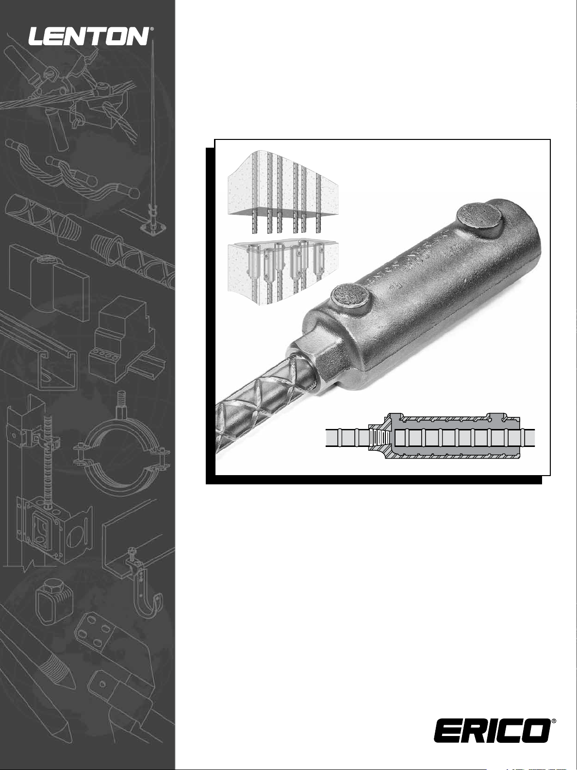
LENTON® INTERLOK
Rebar Splicing System
Revised January 2013
PDF137_B
Page 2

Page 3

Table of Contents
General and Safety Information ii
Foreword iii
Overview iv
1. Precaster Installation PAGE
1.1 Components List 1
1.2 Coupler Dimensions & Determining Cut Length of Reinforcing Steel
– Imperial Units 2
– Metric Units 3
1.3 Coupler Dimensions and Determining Cut Length of Reinforcing Steel – Transitions
– Imperial Units 4
– Metric Units 5
1.4 How to Determine Inlet and Outlet Straight Tube Lengths 6
1.5 Locating Inlet/Outlet Tubes for Pump Filling Application 7-8
1.6 Coupler Installation Procedures at Precasting Plant 9-10
2. Job Site Grouting
®
2.1 Quantity of LENTON
INTERLOK Splices per Bag of HY10L 11
2.2 HY10L Mixing Instructions 12-13
2.3 Hot and Cold Weather Grouting Instructions 14-15
2.4 Gravity Fill Installation Instructions for HY10L Filler Material 16-17
2.5 Pump Fill Installation Instructions for HY10L Filler Material 18-19
2.6 Grouting Troubleshooting Guide 20
2.7 HY10L Filler Material Product Specification* 21
*MSDS Available – Contact ERICO
www.erico.com
i
Page 4

IMPORTANT – General and Safety Information
A. Only ERICO authorized materials should be used to make LENTON® INTERLOK Rebar Splices.
1. Do not splice except as detailed in the instructions.
2. Do not alter materials without manufacturer authorization.
3. Do not substitute for ERICO authorized materials.
Failure to comply with the above may result in hazards to the individual, improper splices, or damage to items being connected.
B. Make splices in accordance with described splicing procedures and in consideration of surrounding conditions and personnel.
Refer to the HY10L MSDS prior to beginning work with the grout.
1. Personnel should be properly trained in the use of this product.
2. Avoid breathing concentrations of grout dust as it may be hazardous to health. Refer to MSDS for control measures.
3. Avoid skin contact with grout slurry.
C. Unusual applications or conditions may exist which require special considerations.
1. Provide adequate ventilation where natural air flow is not sufficient to prevent personnel from breathing
concentrations of dust.
D.
Storage of HY10L Filler Material should be in a clean, dry, secure area and should be restricted to access by authorized personnel
only. Discard any torn, wet, or otherwise damaged bags. Discard any bags which have become wet or where material clumping
is observed. Material consistency should be that of a free flowing fine powder.
E. To determine the date of HY10L manufacture, refer to the lot number located on the end panel of each bag.
The manufacturing date can be determined as shown below:
X YY MM DD ZZ
Example A1210051J: Material produced October 5, 2012 batch 1 of the day. The 1st Alpha character “A” is a production
code. The last character “J” is an optional placeholder for the manufacturer (it may or may not be used and printed on
the bag).
DO NOT USE any HY10L which is in excess of 1 year beyond the manufacturer’s date noted on the package.
F. Refer to grout mixing directions located on the bag for proper mixing guidelines or contact ERICO.
G. Refer to Pump Fill or Gravity Fill Installation Instructions located in this Manual for proper installation guidelines.
H. The recommended temperature range of the HY10L Filler Material is 50 to 80°F (10 to 27°C). At no time during placing and
curing should the temperature of the coupler, rebar, and HY10L be allowed to be outside the range of 40 to 90°F (4 to 32°C).
I. Do not use more than 13.5% water by weight (0.8 gallons or 3.0L per 50 lb. (22.7Kg) bag) or obtain an ERICO Flow
Template reading of greater than 6.5” (16.5cm). Do not add any additives or admixtures to the HY10L.
J. Keep walls and panels undisturbed for at least 24 hours [at 68°F (20°C)]. Movement during curing will result in decreased
splice performance. Temperatures below 50°F (10°C) considerably increase the time it takes freshly placed grout to develop
strength. Therefore, there is a risk of damage or collapse if the structure is loaded before it develops adequate strength.
This
by the structural
K. The HY10L Filler Material is designed to be used with the LENTON INTERLOK Rebar Splicing System. Unauthorized use of
other grouts will void all warranties, whether expressed or implied.
L. While working on the job site, observe all Federal, State, and Local safety regulations.
1. Wear a hard hat and safety glasses.
2. Wear gloves to avoid cuts.
3. Prior to installing connections, read and understand all operating, mixing, and safety instructions found in this Manual
and on the HY10L bag.
M. Deviations from the specified recommendations outlined in this manual will void all warranties. It is the responsibility of the
user(s) to observe proper grouting conditions, (e.g., temperature, water to cement ratio, placing consistency, etc.)
quality workmanship.
N. ERICO reserves the right to revise these documents contained herein for any reason, including but not limited to conformity
To assure that you have the most recent edition of this manual, contact ERICO.
strength may vary depending on the structural loading and the temperature. Therefore, the strength must be determined
engineer and should be based upon the expected construction loading.
and utilize
with standards established by various agencies, utilization of advances in the state of technical arts, or the reflection of
changes in the design of any components, techniques, or procedures described or referred to herein.
www.erico.com
ii
Page 5

Foreword
The LENTON® INTERLOK System has been designed to exceed the ACI® 318 Building Code Type 1 requirement of
developing, in
A615 Grade 60 rebar specifications.
and AS3600 for specified tensile strength performance. In order to achieve these stress levels, it is imperative that
all procedures shown in this manual and on the HY10L bag are closely followed.
HY10L High-Strength Filler Material has been developed exclusively for use in the
Use of other grouts will void all warranties and product claims, both expressed or implied.
Before beginning any project, we ask that the ENTIRE manual be reviewed, and thoroughly understood.
For technical assistance, on the LENTON INTERLOK System, or other ERICO Reinforcing Steel Splices,
please contact your local ERICO office.
both tension and compression, a minimum of 125 percent of specified yield for ASTM® A706 and
In addition, the system will meet the requirements for ACI 318 Type 2, BS8110
LENTON
INTERLOK system.
WARNING
1. ERICO products shall be installed and used only as indicated in ERICO product instruction sheets and training materials. Instruction sheets are available at www.erico.com and from your ERICO customer
service representative.
2. ERICO products must never be used for a purpose other than the purpose for which they were designed or in a manner that exceeds specified load ratings.
3. All instructions must be completely followed to ensure proper and safe installation and performance.
4. Improper installation, misuse, misapplication or other failure to completely follow ERICO’s instructions and warnings may cause product malfunction, property damage, serious bodily injury and death.
The customer is responsible for:
a. Conformance to all governing codes.
b. The integrity of structures to which the products are attached, including their capability of safely accepting the loads imposed, as evaluated by a qualified engineer.
c. Using appropriate industry standard hardware as noted above.
SAFETY INSTRUCTIONS:
All governing codes and regulations and those required by the job site must be observed. Always use appropriate safety equipment such as eye protection, hard hat, and gloves as appropriate to the application.
www.erico.com
iii
Page 6

Overview
The LENTON® INTERLOK Mechanical Reinforcing Steel Splice is designed to connect #5 (16 mm) through #18 (57 mm) rebar,
conforming to ASTM
the LENTON
®
taper threaded system in conjunction with a special
rial (grout). Assembly of the connection is normally
the coupler at a precaster’s plant prior to placement of concrete in the precast member. The connection is completed at
job site, where the exposed dowel of the adjoining panel is positioned within the interior of the coupler. The filler material
®
A615/A615M, A706/A706M, BS4449, CSA G30.18 or AS1302 standards. The connection incorporates
high-early strength cementitious volume stable filler mate-
done in two separate stages: The LENTON threaded end is fastened to
the
is
either poured or pumped into the cylindrical end of the coupler. The coupler can be oriented in either a vertical, inclined or
horizontal position.
The filler material is a special ready-to-use grout, designed to maintain fluidity for an extended period of time while achieving
a high-early-strength. It is a metallic, volume-stable, material capable of developing in excess of 8,500 psi (58.6 MPa)
compressive strength at 28 days. To ensure a proper connection, the addition of water must be maintained in strict
accordance with ERICO recommended procedures. In addition, the temperature of the grout during placing and curing must
be maintained within the recommended guidelines. Misapplication or use of grouts other than ERICO brand of HY10L without ERICO approval voids all warranties, both expressed or implied.
The coupler is produced as a casting and LENTON taper threads are machined under strict Quality Control guidelines. Taper
threading of the rebar ends are produced using ERICO’s equipment. Prethreaded bars can be provided from ERICO’s network
of threading centers, or by positioning a threader at the precasters plant. The threads are right hand and tapered to match
the accompanying coupler.
When assembled in accordance with ERICO recommended procedures, the splice will meet or exceed the ACI 318, BS8110,
AS3600, UBC
®
or IBC® Building Code requirements.
www.erico.com
iv
Page 7
Precaster Installation
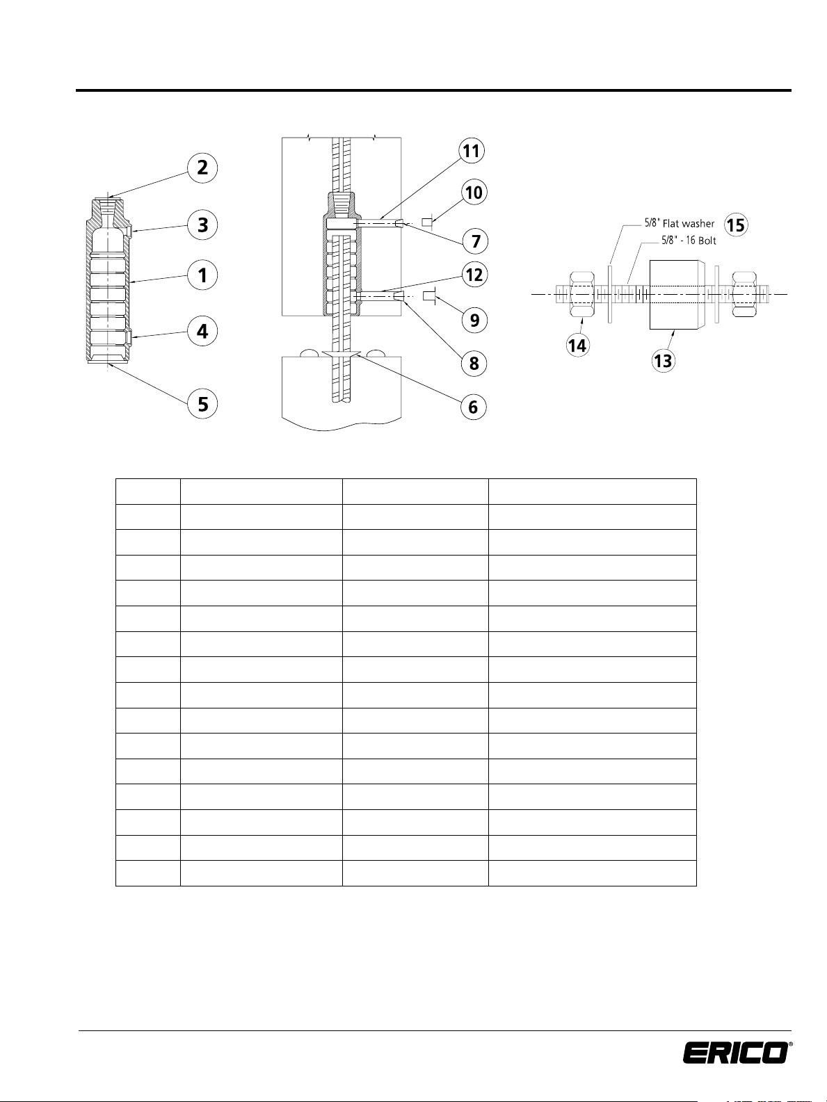
I.I Component List:
Item No. Description Standard Item Included Separate Order
®
1 LENTON
INTERLOK Coupler Standard
2 Thread Protector Standard
3 1/2” Outlet Plug Order separately or Obtain locally
4 3/4” Inlet Plug Order separately or Obtain locally
5 Dust Cap Order separately or Obtain locally
6 Sealing Disc Order separately
7 1/2” (13mm) Plastic Dust Cap Order separately or Obtain locally
8 3/4” (19mm) Plastic Dust Cap Order separately or Obtain locally
9 3/4” (19mm) Rubber Stopper Order separately or Obtain locally
10 1/2” (13mm) Rubber Stopper Order separately or Obtain locally
11 1/2” (13mm) SCH40 PVC Obtain locally
12 3/4” (19mm) SCH40 PVC Obtain locally
13 Urethane Grommet
14 5/8-16 x 3-1/2 Bolt & Nut
15 5/8 Flat Washer
a
a
a
Order separately
Order separately
Order separately
c
c
b
b
b
b
b
b
b
a Included with Form Mounting Fixture
b Non-stock item typically found locally
c Not supplied by ERICO
www.erico.com
1
Page 8
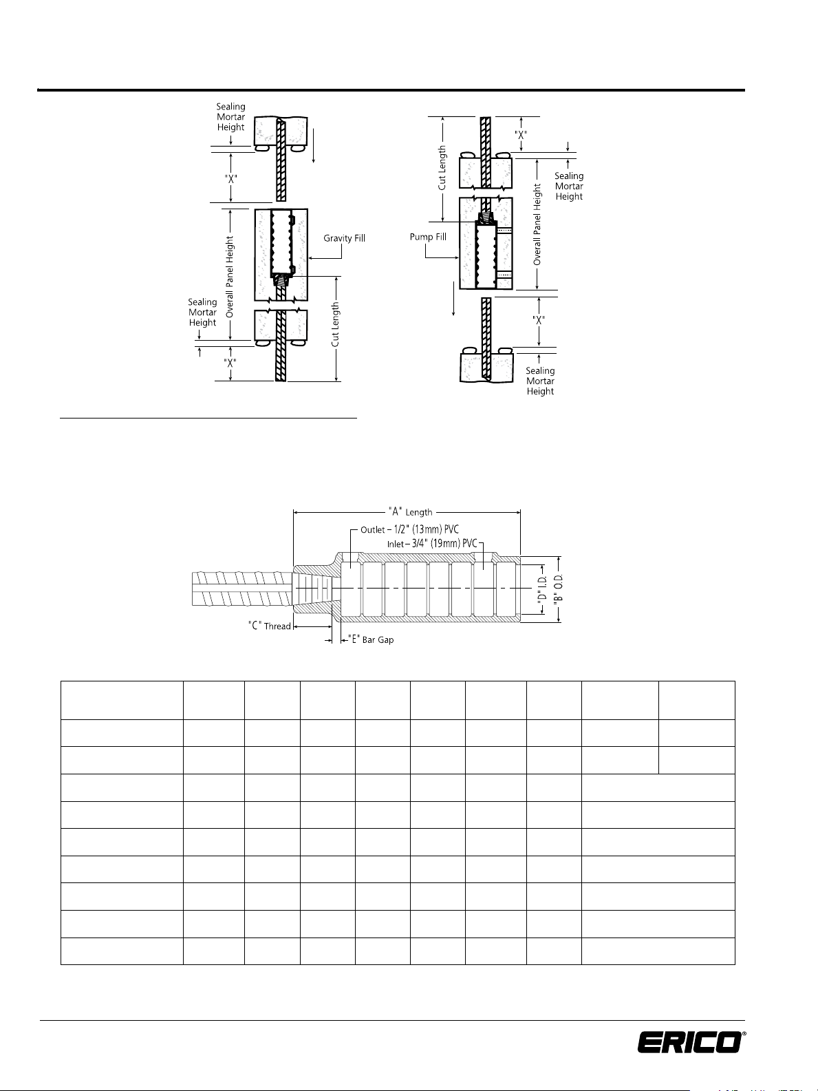
1.2 Coupler Dimensions and Determining Cut
Length of Reinforcing Steel – Imperial Units
To Determine Typical Cut Length of Reinforcing Steel:
Maximum Cut Length
Gravity or Pump Condition = [Overall Panel Height - E] + Sealing Mortar Height
Minimum Cut Length = Maximum Cut Length - 1 Bar Diameter Note: For last lift, reduce cut length as
Dowel Length = X + Sealing Mortar Height determined by design requirements
Imperial Units:
Rebar Size
in-lb Canadian
#5 15M LK5 7-13/16” 2-9 /16” 7/8” 1-7/8” 13 /16“ 6-1/ 8” 5-1/4” 5-1/2”
#6 20M LK6 7-13/16” 2-9 /16” 1-1/ 8” 1-7/8” 9/16” 6-1/8 ” 5 -1/4” 5-3/8”
#7 --- LK7 7-13/16” 2-9 /16” 1-1/4” 1-7/8” 7/16” 6-1/8” 5-1/4”
#8 25M LK8 8-5/8” 2 -11/16” 1-3/8” 2” 1/4” 7” 6”
#9 30M LK9 9 -3/4” 2-13/ 16” 1-1/ 2” 2-1/8” 1/4” 8” 6-7/8”
#10 --- L K10 10-13 /16” 3” 1-9/16” 2-5/16” 1/4” 9” 7-3/4”
#11 35M LK11 11-15 /1 6” 3-1/8” 1 -11/16” 2-7/16” 3/8” 9-7/8” 8-1/2”
#14 45M LK T14 15 -3/16” 3-11/ 16” 2-1/8” 2-3/4” 5/16” 12-3/4” 11”
#18 55M LKT18 20-5/16” 4-1/2” 2-3/4” 3-1/4” 9/16” 17” 14-3/4”
* “X” Min. Type 1 will develop 125% of the specified yield strength of the rebar in tension and compression ( 125% f
** “X” Min. Type 2 meets Type 1 and will develop the specified tensile strength of the rebar in tension ( f
Contact ERICO for rebar sizes not listed.
www.erico.com
Coupler
Part No.
“A” “B” “C” “D”
2
Reference
).
u
“E”
“X”
Max.
).
y
“X” Min.
Typ e 1*
“X” Min.
Type 2**
Page 9
1.2 Coupler Dimensions and Determining Cut
Length of Reinforcing Steel – Metric Units
To Determine Typical Cut Length of Reinforcing Steel:
Maximum Cut Length
Gravity or Pump Condition = [Overall Panel Height - E] + Sealing Mortar Height
Minimum Cut Length = Maximum Cut Length - 1 Bar Diameter Note: For last lift, reduce cut length as
Dowel Length = X + Sealing Mortar Height determined by design requirements
Metric Units:
Rebar Size mmCoupler
Part No.
16 LK5 145575 199 65 22 48 21 156 134 140
20 LK6 145580 199 65 29 48 14 156 134 136
22 LK7 145585 199 65 32 48 11 156 134
25 LK8 145590 219 68 35 51 6 178 153
28 LK9 145595 248 72 38 54 6 203 175
32 LK10 145600 275 76 40 59 6 229 197
36 LK11 145605 303 79 43 62 10 251 215
40 LK40 145610 386 94 58 70 4 324 284 318
43 LKT14 145611 386 94 54 70 8 324 281
50 LKT50 145615 516 114 71 83 13 432 382 426
57 LKT18 145620 516 114 70 83 14 432 375
* “X” Min. Type 1 will develop 125% of the specified yield strength of the rebar in tension and compression ( 125% f
** “X” Min. Type 2 meets Type 1 and will develop the specified tensile strength of the rebar in tension ( f
Contact ERICO for rebar sizes not listed.
Coupler
Article
No.
“A”
mm
“B”
mm
“C”
mm
“D”
mm
).
u
“E”
Reference
mm
). All table dimension in mm
y
“X”
Max.
mm
“X” Min.
Typ e 1*
mm
“X” Min.
Type 2**
mm
www.erico.com
3
Page 10

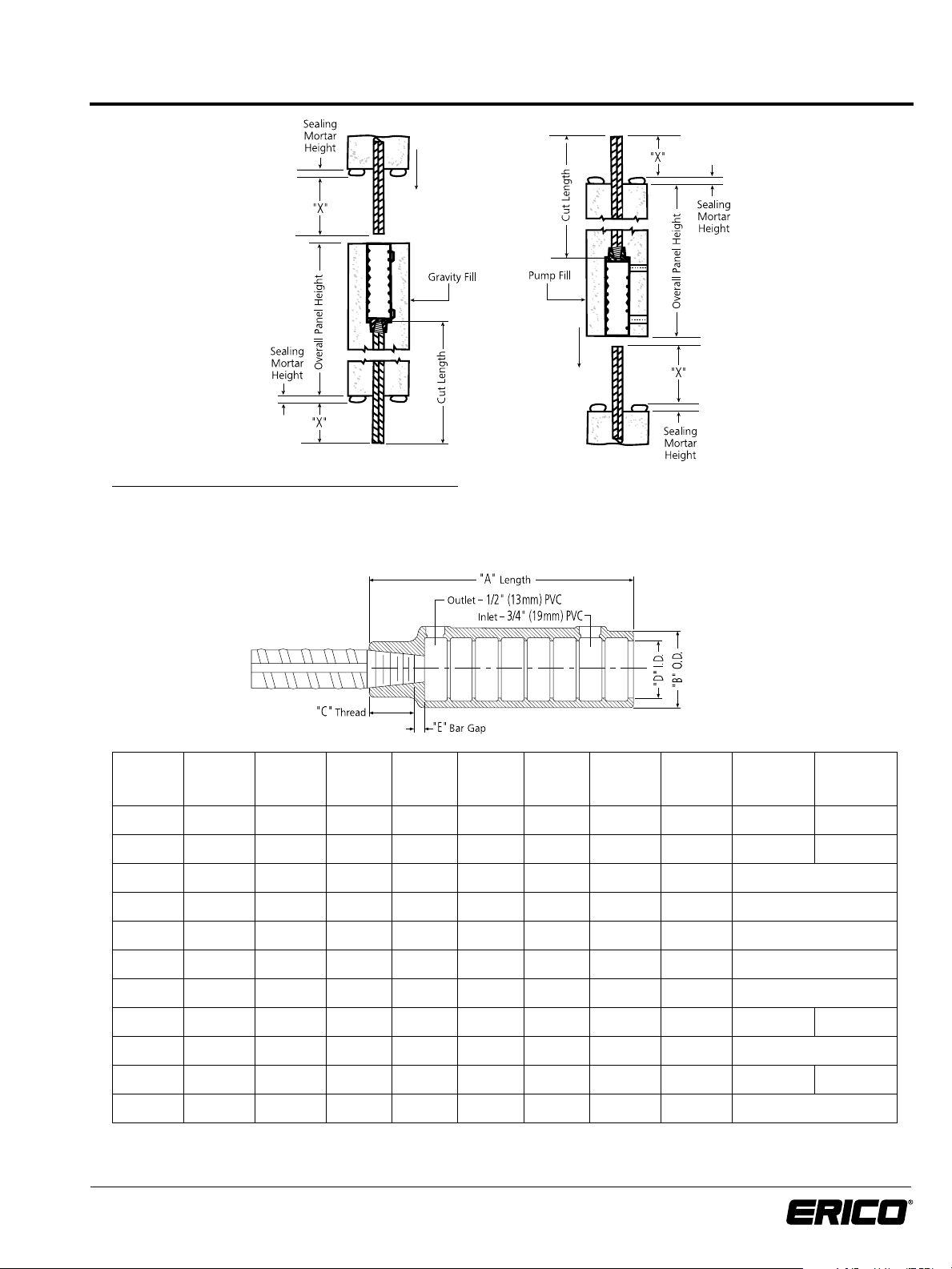
1.3 Coupler Dimensions and Determining Cut
Length of Reinforcing Steel – Transitions – Imperial Units
To Determine Typical Cut Length of
Reinforcing Steel:
Maximum Cut Length
Gravity Condition =
[Overall Panel Height - E]
+ Sealing Mortar Height
Pump Condition =
[Overall Panel Height - E - Xmax]
+ Ymax + Sealing Mortar Height
Minimum Cut Length =
Maximum Cut Length - 1 Bar Diameter
Dowel Length =
X + Sealing Mortar Height
Y + Sealing Mortar Height
Note: For last lift, reduce cut length as
determined by design requirements.
Imperial Units:
Rebar Size
in-lb
#6 to #5
#6+ to #5 LK6 Gravity 7-13/16” 2-9/16” 1-1/8” 1-7/8” 9/16” 6-1/8” 5-1/4” 5-3/8” 6-1/8” 5-1/4” 5-1/2”
#7 to #6
#7+ to #6 LK7 Gravity 7-13/16” 2-9/16” 1-1/4” 1-7/8” 7/16” 6-1/8” 5-1/4” 6-1/8” 5-1/4” 5-3/8”
#8 to #7
#8+ to #7 LK8 Gravity 8-5/8” 2-11/16” 1-3/8” 2” 1/4” 7” 6” 7” 5-1/4”
#9 to #8
#9+ to #8 LK9 Gravity 9-3/4” 2-13/16” 1-1/2” 2-1/8” 1/4” 8” 6-7/8” 8” 6”
#10 to #9+LK109 Pump 10-13/16” 3” 1-1/2” 2-5/16” 5/16” 9” 7-3/4” 8” 6-7/8”
#10+ to #9 LK10 Gravity 10-13/16” 3” 1-9/16” 2-5/16” 1/4” 9” 7-3/4” 9” 6-7/8”
#11 to #10+LK1110 Pump 11-15/16” 3-1/8” 1-9/16” 2-7/16” 1/2” 9-7/8” 8-1/2” 9” 7-3/4”
#11+ to #10 LK11 Gravity 11-15/16” 3-1/8” 1-11/16” 2-7/16” 3/8” 9-7/8” 8-1/2” 9-7/8” 7-3/4”
#14 to #11+LK1411 Pump 15-3/16” 3-11/16” 1-11/16” 2-3/4” 3/4” 12-3/4” 11” 9-7/8” 8-1/2”
#14+ to #11 LKT14 Gravity 15-3/16” 3-11/16” 2-1/8” 2-3/4” 5/16” 12-3/4” 11” 12-3/4” 8-1/2”
#18 to #14+LK1814T Pump 20-5/16” 4-1/2” 2-1/8” 3-1/4” 1-3/16” 17” 14-3/4” 12-3/4” 11”
#18+ to #14 LKT18 Gravity 20-5/16” 4-1/2” 2-3/4” 3-1/4” 9/16” 17” 14-3/4” 17” 11”
* “X” Min. Type 1 and “Y” Min. Type 1 will develop 125% of the specified yield strength of the rebar in tension and compression ( 125% fy ).
** “X” Min. Type 2 and “Y” Min. Type 2 meet Type 1 and will develop the specified tensile strength of the rebar in tension ( f
+ Indicates threaded rebar size
Contact ERICO for rebar sizes not listed.
Coupler
Part No.
+
+
+
+
Condition “A” “B” “C” “D”
LK65 Pump 7-13/16” 2-9/16” 7/8” 1-7/8” 13/16” 6-1/8” 5-1/4” 5-3/8” 6-1/8” 5-1/4” 5-1/2”
LK76 Pump 7-13/16” 2-9/16” 1-1/8” 1-7/8” 9/16” 6-1/8” 5-1/4” 6-1/8” 5-1/4” 5-3/8”
LK87 Pump 8-5/8” 2-11/16” 1-1/4” 2” 3/8” 7” 6” 6-1/8” 5-1/4”
LK98 Pump 9-3/4” 2-13/16” 1-3/8” 2-1/8” 3/8” 8” 6-7/8” 7” 6”
“E”
Reference
“X”
Max.
“X” Min.
Typ e 1*
).
u
“X” Min.
Type 2**
“Y”
Max.
“Y” Min.
Typ e 1*
“Y” Min.
Type 2**
www.erico.com
4
Page 11

1.3 Coupler Dimensions and Determining Cut
Length of Reinforcing Steel – Transitions – Metric Units
To Determine Typical Cut Length of
Reinforcing Steel:
Maximum Cut Length
Gravity Condition =
[Overall Panel Height - E]
+ Sealing Mortar Height
Pump Condition =
[Overall Panel Height - E - Xmax]
+ Ymax + Sealing Mortar Height
Minimum Cut Length =
Maximum Cut Length - 1 Bar Diameter
Dowel Length =
X + Sealing Mortar Height
Y + Sealing Mortar Height
Note: For last lift, reduce cut length as
determined by design requirements.
Metric Units:
Rebar Size mmCoupler
20 to 16
20+ to 16 LK6 Call ERICO Gravity 199 65 29 48 14 156 134 136 156 134 140
22 to 20
22+ to 20 LK7 Call ERICO Gravity 199 65 32 48 11 156 134 156 134 136
25 to 22
25+ to 22 LK8 Call ERICO Gravity 219 68 35 51 6 178 153 178 134
28 to 25
28+ to 25 LK9 145595 Gravity 248 72 38 54 7 203 175 203 153
32 to 28+LK109 Call ERICO Pump 275 76 38 59 8 229 197 203 175
32+ to 28 LK10 145600 Gravity 275 76 40 59 6 229 197 229 175
36 to 32+LK1110 Call ERICO Pump 303 79 40 62 12 251 215 229 197
36+ to 32 LK11 145605 Gravity 303 79 43 62 9 251 215 251 197
40 to 36+LK1411 Call ERICO Pump 386 94 43 70 19 324 284 318 251 215
40+ to 36 LK40 145610 Gravity 386 94 58 70 4 324 284 318 324 215
43 to 36+LK1411 Call ERICO Pump 386 94 43 70 19 324 281 251 215
43+ to 36 LK14 Call ERICO Gravity 386 94 54 70 8 324 281 324 215
50 to 40+LK5040 Call ERICO Pump 516 114 58 83 26 432 382 426 324 284 318
50+ to 40 LKT50 145615 Gravity 516 114 71 83 13 432 382 426 432 284 318
57 to 43+LK1814T Call ERICO Pump 516 114 54 83 30 432 375 324 281
57+ to 43 LKT18 145620 Gravity 516 114 72 83 14 432 375 432 281
* “X” Min. Type 1 and “Y” Min. Type 1 will develop 125% of the specified yield strength of the rebar in tension and compression ( 125% fy ).
** “X” Min. Type 2 and “Y” Min. Type 2 meet Type 1 and will develop the specified tensile strength of the rebar in tension ( f
+ Indicates threaded rebar size
Contact ERICO for rebar sizes not listed.
Part No.
+
LK65 Call ERICO Pump 199 65 22 48 21 156 134 136 156 134 140
+
LK76 Call ERICO Pump 199 65 29 48 14 156 134 156 134 136
+
LK87 Call ERICO Pump 219 68 32 51 9 178 153 156 134
+
LK98 Call ERICO Pump 248 72 35 54 10 203 175 178 153
Coupler
Article
No.
Condition
“A” mm“B” mm“C” mm“D”
mm
“E”
Reference
mm
“X”
Max.
mm
“X” Min.
Typ e 1*
mm
).
u
“X” Min.
Type 2**
mm
“Y”
Max.
mm
“Y” Min.
Typ e 1*
mm
“Y” Min.
Type 2**
mm
www.erico.com
5
Page 12

1.4 How to Determine Inlet and Outlet
Straight Tube Lengths
LENTON
®
Taper
Threaded Rebar
LENTON
®
INTERLOK
Coupler
Outlet Tube 1/2” PVC.
Schedule 40 13mm
Outlet
Inlet
Inlet Tube 3/4” PVC.
Schedule 40 19mm
Distance from the edge of
the panel to the center
line of the coupler.
To Determine Inlet and Outlet Tube Length:
Distance from edge of panel to center line of coupler (minus) “A”.
Rebar Size
in-lb Metric Canadian inches mm inches mm inches mm
#5 16mm 15M LK5 145575 1-3/16” 30 1-7/8” 48 3-15/16” 100
#6 20mm 20M LK6 145580 1-3/16” 30 1-7/8” 48 3-15/16” 100
#7 22mm --- LK7 145585 1-3/16” 30 1-7/8” 48 3-15/16” 100
#8 25mm 25M LK8 145590 1-1/4” 32 1-13/16” 46 4-7/8” 124
#9 28mm 30M LK9 145595 1-5/16” 33 1-13/16” 46 5-7/8” 149
#10 32mm --- LK10 145600 1-7/16” 37 1-13/16” 46 6-7/8” 175
#11 36mm 35M LK11 145605 1-1/2” 38 1-3/4” 44 7-13/16” 198
--- 40mm --- LK40 145610 1-5/8” 41 1-15/16” 49 10-7/16” 265
#14 43mm 45M LKT14 145611 1-5/8” 41 1-15/16” 49 10-7/16” 265
--- 50mm --- LKT50 145615 1-15/16” 49 2-5/16” 59 14-1/4” 362
Coupler
Part No.
Coupler
Article No.
“A” “B” Length “C” Length
#18 57mm 55M LKT18 145620 1-15/16” 49 2-5/16” 59 14-1/4” 362
www.erico.com
6
Page 13

1.5 Locating Inlet/Outlet Tubes for Pump Filling Application
Shearwall
When the Placing Drawings specify a Pump Fill Application, inlet and outlet tubes are required to be installed. For the Pump
Fill Application, many options are available for locating the inlet/outlet tubes. In general, grout can be installed from any face
of the precast member and tube orientation can be to any of the walls of the panel.
In determining where to locate the tubes it is necessary to consider:
1) Ease of access to the tubes at the job site for grouting.
2) Location of the tubes with respect to the exterior facade of architectural panels.
3) The degree of bending of the tubes that may be required.
4) The length of the tubes. Maximum recommended is 3 feet (1 meter)
Examples of inlet/outlet tube configuration:
I. Restricted Access II. Unrestricted Access
Column
Shearwall
Column
LENTON
®
INTERLOK
Coupler & Rebar
Inlet/Outlet Tubes
Materials:
Only rigid schedule 40 PVC tubing is recommended for inlet and outlet tubes. ERICO recommends not using flexible tubing
as this may collapse or kink during casting of the precast member – preventing the coupler from being filled with grout at
the job site.
www.erico.com
7
Page 14

1.5 Locating Inlet/Outlet Tubes for Pump Filling Application
Forming:
Occasionally it is necessary to bend the PVC tube to route it around other connections within the precast panel. The Placing
Drawings should show the correct locations for inlet/outlet ports.
To Properly Bend The PVC Tube:
1)
These are commonly available from electrical supply stores and home hardware centers.
2) Bend the PVC gradually using the maximum possible bend radius.
3) Avoid kinking, collapsing, puncturing or otherwise damaging the PVC tube.
4) Allow the tubes to cool before completing their installation.
5) The ends of the inlet/outlet tubes should be made to sit flush against the surface of the form.
6) Secure the tubes sufficiently to prevent them from moving while the concrete is being poured into the form.
CAUTION: All inlet and outlet tubes must be fully seated in their respective ports on the coupler. The tubes should also be
secured to the form.
Refer to the Coupler Installation Procedures for additional information on installing inlet and outlet tubes.
Heat the PVC gradually and uniformally with an electric heater specifically manufactured for bending
PVC.
www.erico.com
8
Page 15

1.6 Coupler Installation Procedures at Precasting Plant
A. Attaching Coupler To Rebar:
1. Remove the thread protector. Examine threaded bar end to make sure it is undamaged and clean.
If cleaning is required, a wire brush should be used.
2.
Determine whether the coupler is the correct size for the bars being spliced. Each coupler is identified
size and the part number (see chart). Remove the internal thread protector if installed.
3. Install the coupler by rotating by hand until tight - approximately 4 turns (Right Hand Thread).
4. While holding the bar stationary, rotate the coupler with a standard 18” pipe wrench until the connection is fully
tightened (see figure).
with the bar
Rebar Size
in-lb Metric Canadian ft-lb N•m
#5 16mm 15M LK5 145575 90 120
#6 20mm 20M LK6 145580 120 180
#7 22mm --- LK7 145585 160 220
#8 25mm 25M LK8 145590 200 270
#9 28mm 30M LK9 145595 200 270
#10 32mm --- LK10 145600 200* 300
#11 36mm 35M LK11 145605 200* 300
--- 40mm --- LK40 145610 200* 350
#14 43mm 45M LKT14 145611 200* 350
--- 50mm --- LKT50 145615 200* 350
#18 57mm 55M LKT18 145620 200* 350
†
Metric and Imperial values are not a direct conversion.
* For Americas only
Coupler
Part No.
Coupler
Article No.
Inspection Wrench Setting
†
Comment on Tightness:
®
Proper tightness may be checked by the installer using a LENTON
brand of inspection wrench. Refer to chart for inspection
wrench settings.
NOTE: The inspection wrench will emit a “click” that can be felt as well as heard when the inspection wrench
setting noted in the chart has been reached.
B. Attach The Coupler To The Form:
Follow the instructions provided with the Form Mounting Fixture. It is important that the Form Mounting Fixture is tightened
sufficiently so that the urethane grommet is fully expanded thereby preventing cement from entering the coupler
www.erico.com
9
.
Page 16

1.6Coupler Installation Procedures at Precasting Plant
C. Install Inlet and Outlet Tubes:
Refer to the Placing Drawings to determine if inlet/outlet tubes are required. If not required (Gravity Fill):
that the inlet/outlet ports are plugged and sealed with the supplied rubber plugs.
If inlet/outlet tubes are required (Pump Fill):
1. Install the inlet and outlet tubes into the ports according to the Placing Drawing Specifications. It is
follow these specifications to assure that the ports are correctly located for pump filling and that the tubes are cut to
the correct length. Some experimentation with tube lengths may be necessary to aid in determining proper tube
lengths. Also, it may be necessary to bend the PVC tubes slightly to assure proper port location.
2. Once the tubes have been cut to length and oriented properly, it may be necessary to tap the tubes lightly with a
hammer to assure that they are seated fully inside the ports on the coupler.
3. It is important that the inlet/outlet tubes fit snugly inside the ports on the coupler. If this joint is not tight, apply
adhesive to secure the tubes into the inlet/outlet ports.
4. Once the tubes are positioned, seal the ends of the tubes with rubber stoppers.
D. Inspect The Installation:
To avoid possible intrusion of cement into the LENTON® INTERLOK coupler it is important that the following areas be inspected
prior to pouring the precast panel.
1. Check to see that the LENTON thread is properly installed and tight. Refer to page 9 and the table with wrench
settings.
2. Make sure inlet/outlet ports are sealed. If tubes are used, make sure tube is tightly seated in the port and that the
opposite end is plugged to prevent entry of concrete. Refer to the Placing Drawings to make sure the inlet/outlet
tubes are located in the correct position for pump filling.
Check to make sure
important to
3. Inspect Form Mounting Fixture and urethane grommet for proper seal to prevent entry of concrete.
4. Check that the coupler is perpendicular to the form end plate and that it is tightly seated.
5. Check the length of protruding dowel on opposite end of form. Make sure the dimensions meet those on the
Placing Drawings.
E. Pour Concrete Into Form:
After all other requirements of the Placing Drawings are complete, concrete can be poured.
When pouring the concrete into the form make sure not to disturb any of the PVC tubes as this may cause the tube to slip
out of the inlet/outlet ports or cause the tubes to move away from the outside surface of the form which will make locating
them at the job site difficult.
F. Remove Forms and Inspect:
Once the concrete is cured, remove the Form Mounting Fixtures and the forms, inspect all the inlet/outlet tubes to make sure
that they are clean and free of any blockages and not covered with cement. Any cement inside the coupler or PVC tubes
should be immediately cleaned out.
Finally, to prevent contaminants from entering the clean coupler, insert a plastic dust cover into the open mouth of the coupler.
www.erico.com
10
Page 17

Job Site Grouting
2.1 Quantity of LENTON
HY10L is provided in 50 pound (22.7 Kg) bags
®
INTERLOK Splices per Bag of HY10L
Rebar Size
in-lb Metric Canadian Quarts Liters
#5 16mm 15M LK5 145575 1/3 0.33 24
#6 20mm 20M LK6 145580 1/3 0.31 25
#7 22mm --- LK7 145585 1/3 0.30 26
#8 25mm 25M LK8 145590 3/8 0.37 21
#9 28mm 30M LK9 145595 1/2 0.45 17
#10 32mm --- LK10 145600 5/8 0.57 13.5
#11 36mm 35M LK11 145605 3/4 0.67 11.5
--- 40mm --- LK40 145610 1-1/4 1.13 7
#14 43mm 45M LKT14 145611 1-1/8 1.07 7
--- 50mm --- LKT50 145615 2 1.93 4
#18 57mm 55M LKT18 145620 1-3/4 1.66 4.5
Coupler
Part No.
Coupler
Article No.
Theoretical Volume of Grout
Required to Fill Coupler
Estimated Number
of Splices per 50 lb.
(22.7 Kg) Bag
The values given in the above table are estimates only, assuming maximum rebar embedment in the coupler.
Actual values will vary depending on job site practice and conditions.
It is important when determining the amount of grout for the particular application to consider adding an additional
10% during hot and cold weather grouting. This is particularly important during hot weather grouting where there
may be more grout discarded due to the reduced working times and shorter potlife.
For pump fill applications it is important to include the volumes of the inlet and outlet tubes in the determination.
These volumes become significant in applications where the precast members are unusually thick and the PVC inlet
and outlet tubes become long.
www.erico.com
11
Page 18

2.2 HY10L Mixing Instructions
1 Preparation:
1.1 Materials and Equipment Needed for Proper Use and Installation:
To permit rapid and continuous work with the HY10L it is recommended that all necessary tools and materials be as near to
the work area as possible. See additional equipment list for pump fill installation.
Potable water Mixing bucket Grout pump
Flow Template Kit (Part # LK400) 4 oz. (115 ml) measuring cup Plastic plugs for inlet/outlet tubes
Electric mixer 1 gallon (3L) graduated water measuring pail 2” (50mm) Cube test molds
Paddle or propeller mixing blade Thermometer (hot/cold weather) Spatula
1.2 Preparatory work:
Before beginning work with HY10L, remove all debris, oil, dirt, and moisture from the areas and couplers to be grouted.
Make sure all panels and forms are securely anchored to prevent movement during placing and curing. Verify that the HY10L
grout is not beyond the 1 year shelf life by checking the manufacturing date on the bag.
To ensure a quality structural connection it is important to provide for routine quality control during the mixing,
grouting, and
installation.
NOTE: For a list of suitable equipment and accessories see the manual or contact ERICO.
1.3 Grout temperatures: Refer to Hot and Cold Weather Instructions
!!CAUTION!!
When grouting in cold weather, precautions MUST be taken to keep the HY10L from freezing (32 degrees F;
0°C), during
initial setting, as this will result in insufficient strength. Refer to Cold Weather Instructions in this manual.
2. Sample Mix:
To determine the correct amount of water to add to the HY10L, it is necessary to mix one 50 lb. (22.7 kg)
2.1
bag as a trial batch.
1. Mix the HY10L according to the mixing steps described in the next section.
2. Use 0.7 gallons of potable water to one bag of dry HY10L. [0.7 gallons is equivalent to 90 fl. oz., 2.8 qts., 2.7 L,
or 7-1/2 pop cans (12 oz. size) of water.]
3. Determine the fluidity (spread) by using the Flow Template Kit (ERICO part # LK400, described below).
4. Add additional water in small measurable increments (for example, 4 oz. or 100 ml) to get a Flow Template
measurement of 5” to 6”.
5. Remix and retest the fluidity of the HY10L after each addition of water.
6. Repeat this procedure (steps 4 to 6) until the recommended spread is achieved.
7. If the fluidity exceeds 6-1/2” as measured on the Flow Template, discard the trial batch and repeat steps 1 thru 8
with a fresh bag of HY10L, making necessary water adjustments.
8. Record the Flow Template measurement and the amount of total water needed and use this amount for further
batches of the same lot.
2.2 Using the Flow Template Kit (LK400): (See Cautions)
A Flow Template Kit can be obtained from ERICO. The Flow Template Kit is used for a modified slump test to determine
water content for the LENTON
cylinder and
a Flow Template (LK405) with preprinted circular dimension rings. This test is to be completed from start to
®
INTERLOK system. The slump test consists of a 2” (51mm) diameter by 4” (102mm) tall
finish within 2 minutes and without interruption. To use the Flow Template:
1. Place the Flow Template on a flat horizontal surface and place the cylinder into the center circle.
2. Fill the cylinder to the top with the HY10L. Tap to remove air bubbles. Slowly lift the cylinder
allowing the HY10L to flow out from the bottom and onto the Flow Template.
3. To determine the fluidity, read the flow diameter (spread) off the Flow Template. Read the spread in two places,
preferably opposite to each other.
4. Average these two readings to determine the fluidity.
www.erico.com
12
the
Page 19

2.2 HY10L Mixing Instructions
It is recommended that the fluidity be measured on every batch (bag) mixed until the user becomes familiar with the system.
Depending on the temperature, the mix size, and the specific application, more or less water may be necessary. Additionally,
the fluidity should be checked at the beginning of each shift and for every NEW LOT of HY10L, or as required by the engineer.
Lot numbers are identified on each bag.
!!CAUTION!!
DO NOT USE MORE THAN 13.5% WATER by weight (0.8 gallons or 3L per 50 lb. (22.7 kg) bag) or obtain a flow template
reading of greater than 6-1/2” (165 mm) as this will result in insufficient strength gain. A flow template reading of below 5”
(127 mm) will make pumping of the HY10L difficult and will reduce the performance of the system.
2.3 Mixing Steps: (See Cautions)
1. Place all the mixing water into the mixing bowl. Add only enough water to meet the flow template requirements.
2. While blending with the mixer, slowly add the HY10L into the water until the bag is empty.
3. MIX THOROUGHLY FOR A MINIMUM OF 5 MINUTES. Longer mix times may be necessary to achieve a uniform
blend. Improper mixing may result in poor strength, due to unevenly mixed materials. Use ONLY full bags of HY10L
for each batch made.
4. To assure a uniform blend, periodically during mixing scrape down the sides of the mixing bucket. The useful
working time of the HY10L is shown in Figure 1 in the Hot and Cold Weather Grouting Instructions section. The
potlife may vary considerably depending on the temperature.
!!CAUTION!!
If any of the items listed below occurs, the material will not develop the required strength and the batch MUST be discarded
and fresh material MUST be used.
1.
Under no conditions should the HY10L be retempered by adding additional water once it has stiffened.
2. Once mixed, if the fluidity of the grout is greater than 6-1/2” (165 mm) as measured on the flow template,
DO NOT ADD ADDITIONAL DRY HY10L to reduce the fluidity.
3. DO NOT ADD cement, sand or any additives or admixtures to the HY10L as this will adversely affect the properties.
4. A mechanical mixer MUST be used to mix the HY10L.
DO NOT MIX BY HAND. Contact ERICO for a list of suitable mixers and accessories.
®
LENTON
INTERLOK Warranty and Conditions:
Contact ERICO for specific terms of the warranty.
Storage:
HY10L should be stored in a cool, dry environment. It is recommended that the HY10L be stored indoors to maintain maximum
shelf life and physical properties. If the bag is damaged or becomes wet, the HY10L must be discarded.
Shelf Life:
HY10L’s shelf life is 12 months from the manufacturing date printed on the bag, when stored in accordance with ERICO
guidelines. HY10L which has been stored beyond 12 months from the manufacturing date or that is beyond the expiration
date should be discarded.
www.erico.com
13
Page 20

2.3 Hot and Cold Weather Grouting Instructions
The HY10L filler material is designed to be used with the LENTON® INTERLOK rebar splicing system. Unauthorized use of
other grouts will void all warranties, whether expressed or implied.
The recommended temperature range for the HY10L filler material is 50 to 80°F (10 and 27°C). At no time during placing
and curing should the temperature of the LENTON INTERLOK coupler, rebar, and HY10L be allowed to be outside the range
of 40 to 90°F (4 and 32°C),
!!CAUTION!! DO NOT ADD ANY admixtures or additives to the HY10L, as this will affect the properties and void all warranties.
3. Hot Weather Grouting:
As with other grouts, in hot weather 90 to 100°F (32 to 38°C) the HY10L may lose workability rapidly, causing flash setting
and loss of compressive strength. In hot weather precautions must be taken to guard against the HY10L from setting too
quickly. To overcome these problems, modify the basic procedures as follows:
1. Store the bags of HY10L in a cool, shaded (preferably indoor) location until the time of use.
2. Use chilled mixing water as close to 33°F (0.6°C) as possible. This can be easily accomplished by placing a block of
ice in a 55 gallon (200L) drum of water. At the time of placement, the freshly mixed grout should be 80°F (27°C)
or below. At no time during placing or curing should the grout temperature be greater than 90°F (32°C).
!!CAUTION!! No pieces of ice must be allowed to be mixed in with the grout as this will result in voids that will
affect the connection performance.
3.
the panels so that the area is kept shaded for at least several hours prior to grouting.
4. Locate the mixer in a shaded area as close to the grouting site as possible. Prior to mixing, cool the mixing bucket
and mixer with chilled water. Drain all excess water thoroughly from the mixer and mixing bucket.
5. Immediately after grouting, cover the areas and panels that were grouted with a damp tarp or burlap for at least
12 hours. Place additional tarps above and around the panels so as to shade the areas that were grouted from the
of water. DO NOT ADD additional water to retemper the HY10L.
!!CAUTION!!
fore, it will be necessary to work quickly with the grout. Premature stiffening and difficulty in pumping and workability may
result in hot weather applications. If the grout becomes too stiff to pump or pour, discard the remaining material and mix a
fresh bag.
For additional information on Hot Weather Grouting, refer to the IBC 2009 and ACI 318, 305R and 301.
4. Cold Weather Grouting:
As with other grouts, in cold weather the HY10L will tend to set up more slowly, therefore, the first 24 to 72 hours are critical.
When grouting in cold weather, modify the basic procedures as follows:
1.
2. The LENTON INTERLOK coupler, the rebar, the panel, and the areas to be grouted should be heated
!!CAUTION!! When using space heaters be sure to observe all manufacturer’s safety guidelines.
!!CAUTION!! Grout should never be placed into frozen concrete or LENTON INTERLOK couplers.
Keep the areas and panels to be grouted covered with a damp tarp or burlap. Place other tarps above
direct sunlight. Do not soak or spray water directly on or around the areas that were grouted so as to create puddles
Mix only one bag at a time. In hot weather the working time of the HY10L will be significantly
Store the bags of HY10L in a warm building at above 50°F (10°C) for 48 to 72 hours prior to grouting.
with space heaters) until the panels have reached a uniform temperature of above 50°F (10°C) through the thickness
(usually about 12-24 hours).
and around
reduced, there-
(for example,
To effectively heat the area, construct a protective enclosure out of wood or canvas. Insulate this enclosure and the areas to
be grouted with sheets of plastic, canvas, or other insulation to prevent heat loss. Follow common fire safety practices when
constructing and heating the working areas.
3. Make sure all couplers and inlet and outlet tubes are clear and free of ice or moisture.
4. Heat the mixing water to no more than 90°F (32°C).
!!CAUTION!! Mixed grout temperatures greater than 90°F (32°C) could cause flash set; mixing water temperatures lower
than 80°F (27°C) will have little effect on raising the grout temperatures.
www.erico.com
14
Page 21

2.3 Hot and Cold Weather Grouting Instructions
5. The HY10L grout at time of placement should be a minimum of 50°F (10°C) and no higher than 80°F (27°C).
®
!!CAUTION!! The LENTON
between 40°F and 90°F (4 to 32°C) (preferably 50 and 80°F; 10 to 27°C), and the grout MUST be protected from freezing
(32°F or 0°C) during curing. Heat should be maintained until the HY10L inside
a minimum compressive strength of 3000 psi (21 MPa). To reach
should be verified with cube tests. Attainment of this strength must be determined by job site cube testing. HY10L that
freezes before reaching this compressive strength will be damaged and can suffer significant strength loss. Refer to ASTM
C-109 and C-942 or contact ERICO.
For additional information on Cold Weather Grouting, refer to the IBC 2009 and ACI 318, 306R and 301.
!!CAUTION!! Temperatures below 50°F (10°C) increase the time it takes freshly placed grout to develop strength. Therefore,
there is a risk of damage or collapse if the structure is loaded before it develops adequate strength. This strength requirement
must be determined by the structural engineer and should be based upon the expected construction loading.
It is a structural engineering decision when to remove bracing - the structural engineer should be consulted
before any bracing is removed regardless of the temperature.
Test Specimens:
Additional test specimens should be made and cured at the job site to assist in determining when bracing can be removed
and when the structure can be placed in service. Unless specimens used for these purposes are cured at the same place and
as nearly as possible under the same conditions as the LENTON INTERLOK connections, the test results can be misleading.
Working Time at Temperature:
INTERLOK coupler, rebar, and the HY10L filler material MUST be maintained at a temperature
the LENTON INTERLOK couplers has reached
this strength at 40°F (4°C) it may take 2 or more days and
NOTE: Refer to Figure 1 for approximate working time as a function of ambient temperature.
To determine the approximate working time of the mixed HY10L grout at the temperature of interest, follow these instructions.
1. On Figure 1 locate the temperature of interest in degrees Fahrenheit on the “X-AXIS”.
2. Using this as a reference, locate vertically the temperature on the line drawn on the graph.
3. Once the point has been located on the graph, then read across horizontally to obtain the Approximate Working
Time on the “Y-AXIS” in minutes at that given temperature.
4. Repeat this procedure for additional temperatures as needed.
FIGURE 1: ERICO brand of HY10L FILLER - Approximate Working Time vs. Temperature
100
90
80
70
60
50
40
30
APPROX. WORKING TIME (MINS)
20
10
0
50 F (10 C) 70 F (21 C) 90 F (32 C)
NOTE: This information is provided for reference only. Actual working times will vary. Contact ERICO when further information is required.
www.erico.com
TEMPERATURE DEGREES F (C)
15
Page 22

2.4 Gravity Fill Installation Instructions
For HY10L Filler Material
The HY10L filler material is designed to be used with the LENTON® INTERLOK rebar splicing system. Unauthorized use of
other grouts will void all warranties, whether expressed or implied. It is important that all individuals responsible for the
grout installation be properly trained.
Gravity Fill:
Measure “A”
Sealing Mortar
Inlet and
Outlet Plugs
Sealing
Mortar
Embedment
Dowel
Length
Length
Rebar Size
in-lb Metric Canadian Inches mm Quarts Liters Inches mm Inches mm
#5 16mm 15M LK5 145575 3/4” 19 1/3 0.33 6-1/8” 156 5-1/4” 134
#6 20mm 20M LK6 145580 3/4” 19 1/3 0.31 6-1/8” 156 5-1/4” 134
#7 22mm --- LK7 145585 1” 25 1/3 0.30 6-1/8” 156 5-1/4” 134
#8 25mm 25M LK8 145590 1-3/8” 35 3/8 0.37 7” 178 6” 153
#9 28mm 30M LK9 145595 1-5/8” 41 1/2 0.45 8” 203 6-7/8” 175
#10 32mm --- LK10 145600 1-3/4” 44 5/8 0.57 9” 229 7-3/4” 197
#11 36mm 35M LK11 145605 2” 51 3/4 0.67 9-7/8” 251 8-1/2” 215
--- 40mm --- LK40 145610 3-3/8” 86 1-1/4 1.13 12-3/4” 324 11-3/16” 284
#14 43mm 45M LKT14 145611 3-3/8” 86 1-1/8 1.07 12-3/4” 324 11” 281
--- 50mm --- LKT50 145615 6-3/4” 171 2 1.93 17” 432 15” 382
#18 57mm 55M LKT18 145620 6-3/4” 171 1-3/4 1.66 17” 432 14-3/4” 375
†
Estimated values only, refer to page 11 for more information.
Coupler
Part
No.
Coupler
Article
No.
Maximum Distance
from Top of Coupler “A”
Theoretical Volume
of Grout Required
to Fill Coupler
†
Embedment Length*
Maximum Minimum
1) Check the lengths of the protruding dowel to make sure the dimensions meet those on the Placing Drawings.
If the protruding dowels are too long, they may be cut to the correct length. If the dowels are too short, the panels
should not be used and the resident engineer should be contacted.
2) Install panel using normal industry practices. *Refer to Pages 2-5 of this manual for correct embedment and dowel lengths.
3) Before beginning work with HY10L, remove all debris, oil, dirt, moisture, and any obstructions from the couplers, rebars,
and areas to be grouted. Blow air into the couplers to confirm they are clean and
dry. Make sure all panels and forms
are securely anchored to prevent movement during placing and curing.
4) To permit rapid and continuous work with the HY10L, it is recommended that all necessary tools and materials be on
hand and as near to the work area as possible. Refer to the Materials and Equipment
Materials and Equipment List located in this manual for tools and materials needed
List on the HY10L bag and to the
for proper gravity fill installation.
5) In order to properly shim and level the precast panels, ERICO recommends that the upper panel is installed and
“dry fit” into its final position, such that, the protruding dowels are fully seated into the ungrouted couplers.
Once these two
is properly positioned.
panels have been brought together, insert the proper shims between the panels so that the assembly
Once the panels have been properly shimmed and leveled, the upper panel can be removed to
allow for filling of the couplers.
www.erico.com
16
Page 23

2.4 Gravity Fill Installation Instructions
For HY10L Filler Material
6) Mix the HY10L according to the mixing directions on the bag. Use only full bags of HY10L for each batch made.
7) Grout may be placed by hand or a grout pump may be used to place the HY10L. Contact ERICO for recommended grout
pumps.
all the manufacturer’s recommended guidelines regarding safety, operations, service, and maintenance.
8) For gravity fill application, pump or pour the HY10L evenly and continuously into the open end of the coupler. Referring
to the table on the following page, fill the coupler to the level “A” shown for the bar
from the top with a ruler and filling the grout to that level. It is acceptable
grout will be removed when the bars are placed inside the coupler. However, for maximum grout economy it is advised
that the couplers be filled with the proper amounts to avoid waste.
!!CAUTION!! DO NOT UNDERFILL the coupler as this will result in reduced connection and performance. Coupler should be
filled completely and fully. Grout should be placed into the coupler in one step and no cold joints should be present.
9) Once the couplers have been filled to the proper level, remove any air that may be trapped in the HY10L by tamping it
with a small diameter rod.
10)
Once the HY10L has been tamped, immediately lower the precast member until it is properly seated and
advised that the precast member be lowered slowly into the coupler to avoid air bubbles. Check to make sure the panels
are level and that grout completely surrounds the rebar to the top.
NOTE:
recommended procedures and all applicable building codes have been observed. If any HY10L leaks out onto the
surface of the precast panel remove it immediately with flushing water to avoid unsightly rust stains.
NOTE: Before using the grout pump, carefully read and understand the Pump Users Manual. It is important
size of interest measuring down
to slightly overfill the coupler, as any excess
aligned. It is
It is recommended that all grouting operations are inspected by the engineer to make sure that all the manufacturer’s
to follow
11)
The decision to remove bracing following grouting must be determined solely by the Structural Engineer.
ensure a quality structural connection, it is important that the grouted couplers in a precast panel or member be secured
and undisturbed by movement, shock, or vibration until the HY10L has reached a compressive strength of at least 3000
psi (21 MPa). Typically this will occur after 1 day at 68°F (20°C), however, this time will vary depending on the temperature
and job site conditions. In cold weather, the curing time will be significantly lengthened (2 or more days at 40°F; 4°C),
therefore, the bracing time may need to be increased. It is strongly recommended that the compressive strength of the
HY10L be checked under job site curing conditions according to the procedures outlined in ASTM C-109 before proceeding
with upper story erection.
12)
Once the installation of the grout is complete and the panels are braced and secured, fill the seam between the two panels
with a dry pack sealing mortar.
!!CAUTION!!
ANY OF THE FOLLOWING ITEMS IF NOT OBSERVED MAY RESULT IN REDUCED CONNECTION PERFORMANCE.
1) Refer to Mixing Directions and Cautions on the LENTON® INTERLOK bag before mixing or doing any work with the
HY10L. Do not use any damaged, wet, or open bags. Do not use grout which is more than 1 year old. These bags
should be discarded in accordance with Federal, State, and Local Regulations.
2)
When pumping, never let the hopper become empty as this will result in air getting into the couplers.
Prepare additional HY10L to keep on hand to avoid this situation.
3) If grouting is interrupted, keep recirculating the HY10L by operating the pump with the nozzle in the hopper. This
movement of the HY10L will aid in keeping it fluid. If the shut down exceeds the l
noted in Figure 1 of Hot & Cold Weather Grouting Instructions,
MUST BE DISCARDED.
4) Never leave a coupler partially filled for an extended period of time. Make sure all couplers are filled
couplers are left ungrouted. Do not underfill the coupler. Place the grout into the
cold joint in the coupler.
5) After grouting, keep the walls and panels undisturbed for at least 24 hours at 68°F (20°C). The final decision to
remove bracing is an engineering decision which must be determined solely by the structural engineer based on job
site conditions.
During cold weather grouting (temperature below 50°F; (10°C) the bracing time must be extended to at least 48
hours to allow the HY10L to gain the required strength.
6) Immediately following check grouting to make sure that no grout has leaked from the coupler.
Refer to the Trouble Shooting Guide located in this manual for additional guidelines.
(for example 60 minutes at 70°F (21°C), THE GROUT
imits of time specified in this manual
coupler in one step – do not create a
In order to
completely and no
www.erico.com
17
Page 24

2.5 Pump Fill Installation Instructions For HY10L Filler Material
(Vertical, Horizontal and Inclined Application as Shown in Figure 1)
The HY10L filler material is designed to be used with the LENTON® INTERLOK rebar splicing system. Unauthorized use of
other grouts will void all warranties, whether expressed or implied. It is important that all individuals responsible for grout
installation be properly trained.
To assure proper filling of the couplers during the pump fill application, it is important to follow these important guidelines.
1) Check the lengths of the protruding dowel to make sure the dimensions meet those on the Placing Drawings. If the
protruding dowels are too long, they may be cut to the correct length. If the dowels are too short, the panels should not
be used and the resident engineer should be contacted.
2) Before beginning work with the HY10L, remove all debris, oil, dirt, and moisture from the areas, rebars, and couplers to
be grouted. Shine a light and blow air into the inlet and outlet tubes to make sure they are free of obstructions and to
confirm a clear passage. Make sure all panels and forms are securely anchored to prevent movement during placing and
curing.
3) Install panel using normal industry practices, using sealing disks and sealing mortar. Refer to Pages 2-5 of this manual for
correct dowel lengths. NOTE: Check to make sure no sealing mortar has entered the coupler. Check that the panels are
properly shimmed and leveled.
4) To permit rapid and continuous work with the HY10L, it is recommended that all necessary tools and materials be on
hand and as near to the work area as possible. Refer to the Materials and Equipment
Component List located in the manual for tools and materials needed
for proper pump fill installation.
List on the HY10L bag and to the
5) A hand-operated or pneumatic grout pump may be used to place the HY10L.
Contact ERICO for recommended grout pumps.
NOTE: Before using the grout pump, carefully read and understand the Pump Users Manual.
It is important to follow all the manufacturer’s recommended guidelines regarding
safety, operations, service, and maintenance.
6) To make sure the pump is clean and free of obstructions, fill the hopper with potable water and operate the pump.
This will also prime the pump and lubricate the inside of the hopper, pump, and hose. Continue to operate the pump
to expel all the water from the hopper and hose.
7) Mix the HY10L according to the mixing directions on the bag. Use only full bags of HY10L for each batch made.
DO NOT MIX grout in the pump hopper.
8) Pour the mixed HY10L into the hopper of the pump, and operate the pump several times to push out any water/cement
slurry that may remain in the hose.
!!CAUTION!! DO NOT USE this water/cement slurry in the coupler as it may result in reduced connection
9) Once a continuous stream of HY10L is flowing from the nozzle, insert the nozzle into the inlet tube at the lower end of
the coupler, as shown.
10)
Pump the HY10L into the coupler slowly and continuously until it flows evenly and freely from the outlet tube on the top
of the coupler. It is recommended that the grout be pumped slowly. This will allow time for excess air bubbles to escape
from the HY10L.
11)
Once the HY10L flowing from the outlet tube is free of air bubbles, stop pumping and insert a plug in the upper outlet
tube. Continue pumping until no additional grout can be pumped into the inlet tube. Then remove the nozzle from the
inlet tube and quickly plug the inlet tube to prevent any escape of HY10L from the coupler. DO NOT REMOVE THE STOPPERS
until after the HY10L has reached final set
the HY10L to leak out of the inlet tube thereby allowing voids in the coupler which will result in decreased connection
performance.
NOTE: Check the joints between the precast panels during and immediately after grouting. If the HY10L has leaked out
of the joint, remove it immediately with flushing water to avoid unsightly rust stains. Check that no HY10L has
leaked out of the coupler and that it is properly filled.
(usually 1 day to harden). Premature removal of the stoppers may allow some of
performance.
It is recommended that all grouting operations are inspected by the engineer to make sure that all the manufacturer’s
recommended procedures and all applicable building codes have been observed.
www.erico.com
18
Page 25

2.5 Pump Fill Installation Instructions For HY10L Filler Material
12)
Once the HY10L has set (usually the next day), the plugs can be removed from the inlet and outlet tubes. The depression
that is left in the tube openings can then be filled with a standard non-metallic mortar. A non-metallic mortar is suggested
for this application to prevent unsightly rust stains that will develop on the surface of the panel or areas that were
grouted. Exposed HY10L will show rust stains. Any exposed HY10L should be covered by plain mortar or other coating
after the HY10L has solidified.
13) Clean grout pump immediately after use with plenty of clean flushing water. Fill the hopper with water and operate the
pump until the water is flowing cleanly and clearly from the nozzle. Rinse off all exterior surfaces with clean flushing
water. Never allow the grout to harden inside the hopper, hose, or nozzle as this will damage the pump.
14) The decision to remove bracing following grouting must be determined solely by the Structural Engineer.
In order to ensure a quality structural connection, it is important that the grouted couplers in a precast panel or member
be secured and undisturbed by movement, shock, or vibration until the HY10L has reached a compressive strength of
least 3000 psi (21 MPa). Typically this will occur after 1 day at 68°F (20°C), however, this time will vary depending on
at
temperature and job site conditions. In cold weather,
the
at 40°F (4°C)), therefore, the bracing time may need to be increased. It is strongly recommended that the compressive
strength of the HY10L be checked under job site curing conditions according to the procedures outlined in ASTM C-109
before proceeding with upper story erection.
Horizontal Applications:
1)
For Horizontal Pump Fill application make sure coupler is sealed sufficiently before pumping the grout into it.
2) Make sure that the rebar is inserted completely into the coupler for the application.
3) Make sure that the coupler is completely filled with grout and that a smooth continuous stream of grout is flowing
from the outlet ports with no air bubbles.
the curing time will be significantly lengthened (2 or more days
!!CAUTION!!
!!CAUTION!!
Refer to Cautions noted under Gravity Fill Installation Instructions for HY10L Filler Material for additional cautions and
information.
www.erico.com
19
Page 26

2.6 Grouting Troubleshooting Guide
I. Recommended Equipment:
1. A large piston or garden sprayer filled with water (4 gallon or larger) 5. Rubber Stoppers
and/or high pressure water hose with sprayer attachment. 6. Electric Drill with masonry bits
2. Compressed Air Source 7. Flashlight
3. Steel Rod – 1/4 to 3/8 inch (6 to 10mm) in diameter 8. Sealing Disks
4. Hammer 9. Dry Pack Mortar
The above equipment should be on-hand and available during grouting.
TROUBLE
Inlet/outlet tubes
1.
not reach the
do
surface.
2. Due to omis-
sions of sealing
disc, inlet tube is
blocked with
sealing mortar
from the joint.
SOLUTION
1. Check and mark the
position of the inlet/
outlet tubes according
to the drawings.
2. Chip down the
marked positions to
the embedded tubes.
Remove all debris.
3. Blow out the tubes
with compressed air
and confirm a clear
passage from the inlet
to outlet tubes.
To aid in confirming a
clear passage, shine a
light into the inlet and
outlet tubes.
IF SEALING MORTAR
IS NOT SET:
1. Lift the top panel off
clean out any sealing
and
inside the
mortar
couplers and any
mortar using high
pressure water.
Once clean, reinstall
2.
the panel and confirm
a clear passage by
shining a light into the
inlet and outlet tubes.
Blow out the tubes
with compressed
loose
air.
TROUBLE
3. Inlet and/or
outlet tube is
blocked with
concrete debris
etc. or by inlet/
outlet plugs
that have become
wedged
inside
the tube.
SOLUTION
FOR DEBRIS ETC.:
1. Insert a steel rod into the
tubes and hammer it to
clear the tube.
2.
Blow out the tubes with
compressed air and
confirm a clear passage
from the inlet and outlet
tubes. To aid in confirming
a clear passage, shine a
light into the inlet and
outlet tubes.
INLET/OUTLET PLUGS:
1.
Use a hooked rod or wire to
scrape plugs out of the tubes.
2. Blow out the tubes with
compressed air and confirm
a clear passage from the
inlet to outlet tubes.
4. Leakage during
pumping of
HY10L grout
from the
joint due to
incomplete
sealing.
1. Seal the joint with rags,
polyurethane, etc.
2. Start regrouting.
www.erico.com
IF THE SEALING
MORTAR IS HARDENED:
1. Insert a steel rod into
the tube, and hammer
it to
strike out the
sealing mortar
blocking the tube.
2. Blow out the tubes
with
and confirm
passage from the inlet
to outlet tubes.
vacuum may also
A
be needed
debris from the interior
of the coupler.
3. Make sure
recommended volume
of grout can be
placed into coupler.
If not, contact the
Structural Engineer.
that is
compressed air
a clear
to remove
20
5. Panel won’t
seat to proper
embedment
length.
1. Dowels are too long –
cut to proper length.
2. Debris in coupler –
remove all debris,
hardened cement, or
water in bottom of
coupler. Blow out with
compressed air and
that coupler
confirm
is clean.
Page 27

2.7 HY10L Filler Material Product Specification
HY10L filler material is a specially formulated ready to use grout designed for use in the LENTON® INTERLOK rebar splicing
system. Unauthorized use of other grouts will void all warranties, whether expressed or implied.
Product Description:
HY10L is a pre-mixed, volume stable, metallic grout. The addition of clean high quality metallic particles gives the HY10L a
ductile and reinforcing effect that enables it to withstand impact, torque, and vibrating loads. HY10L is a high-early strength
grout that offers an extended working range and can be placed at temperatures ranging from 40 to 90°F (4 to 32°C) when
installed in accordance with ERICO guidelines. Due to the excellent fluidity of HY10L, it offers the additional advantage of
being pumped with a commercially available grout pump into the LENTON INTERLOK coupler.
Technical Data:
For grout performance data please contact your regional ERICO office. HY10L grout will typically develop in excess of
8,500 psi
reasonable variations in compressive strength may be encountered. The technical data is based on controlled laboratory tests.
All test specimens should be made according to ERICO guidelines.
Test samples are 2” (50mm) cube specimens cured at 72F (22°C) and tested in accordance with
ASTM C-109-90 and C-942.
PLACING CONSISTENCY:
HY10L, when mixed with approximately 11.5% water by weight of HY10L dry material, will flow to a diameter
!!CAUTION!! Do not use more than 13.5% water by weight (0. 8 gallons or 3L per 50 lb. (22.7 kg) bag) or use
(58.6 MPa) compressive strength in 28 days. Depending on the ambient temperature and other job site conditions,
of 5 to 6 inches (127 - 152 mm) as determined by the Flow Template Kit. Depending on the temperature,
mix size, and the specific application, more or less water may be necessary.
grout which has a flow template reading of greater than 6 1/2” (165 mm). A flow reading of below
5” (127 mm) will make pumping difficult and may result in insufficient filling of the coupler.
This may result in inadequate connection strength. A flow reading greater than 6-1/2” (165 mm)
will result in reduced grout strength and accompanying splice performance. A mechanical mixer
must be used to mix the HY10L. Contact ERICO for a list of suitable mixers and accessories.
Setting Time:
HY10L mixed to the placing consistency and tested in accordance with ASTM C-191, will have a time of initial setting
of about 2-1/2 hours at 68°F (20°C), (working time of 1 hour).
Packaging:
HY10L is packaged in 50 lb. (22.7 Kg) multiply moisture resistant bags for optimum performance and shelf life.
The HY10L has a shelf life of 12 months from the manufacturing date printed on the bag, when stored in
accordance with ERICO guidelines. Do not use grout that is beyond the expiration date.
Temperature Guidelines:
The preferred temperature range for the splicing system is between 50 and 80°F (10 and 27°C). As with all grouts,
the HY10L, LENTON INTERLOK coupler, and rebar must be maintained at a temperature between 40 and 90°F
(4 and 32°C). Refer to Hot and Cold Weather Installation Instructions located in this manual for complete guidelines.
www.erico.com
21
Page 28

www.erico.com
AUSTRALIA
Phone 1-800-263-508
Fax 1-800-423-091
BELGIUM
Phone 0800-757-48
Fax 0800-757-60
BRAZIL
Phone +55-11-3623-4333
Fax +55-11-3621-4066
CANADA
Phone +1-800-677-9089
Fax +1-800-677-8131
CHINA
Phone +86-21-3430-4878
Fax +86-21-5831-8177
DENMARK
Phone 808-89-372
Fax 808-89-373
FRANCE
Phone 0-800-901-793
Fax 0-800-902-024
GERMANY
Phone 0-800-189-0272
Fax 0-800-189-0274
HUNGARY
Phone 06-800-16538
Fax +39-0244-386-107
INDONESIA
Phone +62-21-575-0941
Fax +62-21-575-0942
ITALY
Phone 800-870-938
Fax 800-873-935
MEXICO
Phone +52-55-5260-5991
Fax +52-55-5260-3310
NORWAY
Phone 800-100-73
Fax 800-100-66
POLAND
Phone +48-71-349-04-60
Fax +48-71-349-04-61
SINGAPORE
Phone +65-6-268-3433
Fax +65-6-268-1389
SPAIN
Phone 900-993-154
Fax 900-807-333
SWITZERLAND
Phone 0800-55-86-97
Fax 0800-55-96-15
THAILAND
Phone +66-2-267-5776
Fax +66-2-636-6988
UNITED ARAB
EMIRATES
Phone +971-4-881-7250
Fax +971-4-881-7270
UNITED KINGDOM
Phone 0808-2344-670
Fax 0808-2344-676
CHILE
Phone +56-2-370-2908
Fax +56-2-369-5657
ACI is a registered trademark of American Concrete Institute.
ASTM is a registered trademark of American Society for Testing and Materials.
IBC is a registered trademark of International Code Council.
UBC is a registered trademark of International Conference of Building Officials Corporation.
Copyright ©2004, 2010, 2012, 2013 ERICO International Corporation. All rights reserved.
CADDY, CADWELD, CRITEC, ERICO, ERITECH, ERIFLEX, and LENTON are registered trademarks of ERICO International Corporation.
HONG KONG
Phone +852-2764-8808
Fax +852-2764-4486
NETHERLANDS
Phone 0800-0200-135
Fax 0800-0200-136
SWEDEN
Phone 020-790-908
Fax 020-798-964
UNITED STATES
Phone 1-800-753-9221
Fax +1-440-248-0723
PDF137_B C1430IS12WWEN 0.1M0613
 Loading...