

Page 1
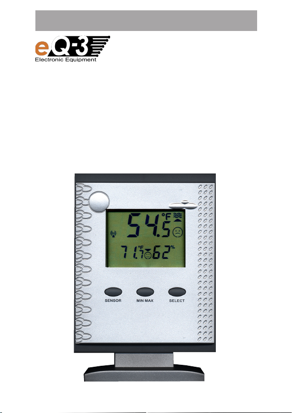
OPERATING INSTRUCTIONS
Wireless
Temperature Station
PTD 300 US
1
Page 2

2
These operating instructions belong with this product.
They contain important information for putting it into
service and operating it. This should be noted also when
this product is passed on to a third party.
Therefore look after these operating instructions for future
reference!
In this manual mentioned sensors are not included in delivery.
For the installation, addressing and commissioning of this sensors, please refer to the operating instructions supplied with the
unit.
Table of Contents:
1. Introduction .................................................................................4
1.1. Intended use ................................................................................4
2. Scope of delivery .........................................................................5
3. Terminology .................................................................................5
4. Features and functions ................................................................6
4.1. Displaying the indoor temperature and air humidity....................6
4.2. Displaying of one of a maximum of 9 outdoor sensors
(temperature/air humidity)............................................................6
4.3. Frost warning ...............................................................................6
4.4. Temperature alarm .......................................................................6
5. Safety instructions .......................................................................7
6. Battery and environment instructions ..........................................8
7. Preparation for operation, commissioning ..................................8
7.1. Commissioning the base station .................................................9
8. Controls and indicators .............................................................10
9. Operation ...................................................................................12
9.1. Key functions .............................................................................12
9.2. Selecting of the sensors to display ...........................................12
9.2.1. Display panel A - pool sensor ....................................................12
9.2.2. Display panel B - indoor or outdoor sensor ..............................13
Page 3

9.3. Displaying MIN/MAX values ......................................................14
9.4. Selecting temperature metered value (Temp./Dewpoint) ..........15
9.5. Frost warning .............................................................................15
9.6. Activating the temperature alarm ..............................................16
9.7. Switch off audio warning during alarm ......................................16
10. Configuration .............................................................................17
10.1. Selecting temperature unit ........................................................17
10.2. Setting the temperature alarm values .......................................17
10.3. Enable/Disable the audio warning .............................................20
10.4. Setting the comfort temperature range of display panel A .......21
11. Other functions and settings ....................................................23
11.1. Commissioning of new sensors ................................................23
11.2. Reset to factory settings............................................................23
11.3. Receiving indicator ....................................................................23
11.4. Frost warning .............................................................................24
12. Changing batteries ....................................................................24
12.1. Base station ...............................................................................24
12.2. Combination sensor, outdoor sensors, pool sensor ..................24
13. Troubleshooting .........................................................................25
14. Range ........................................................................................27
15. Maintenance and cleaning.........................................................28
15.1. General ......................................................................................28
15.2. Cleaning base station ................................................................28
16. Handling ....................................................................................29
16.1. General ......................................................................................29
16.2. Base station ...............................................................................29
17. Terminology ...............................................................................30
17.1. Comfort indicator ......................................................................30
17.2. Dewpoint ...................................................................................30
18. Disposal .....................................................................................31
18.1. General ......................................................................................31
19. Specifications ............................................................................31
20. FCC-Information ........................................................................32
3
Page 4

4
1. Introduction
Dear Customer,
Thank you for purchasing this product.
The product has been EMC-tested and thus meets the requirements
of the valid national guidelines. See also FCC-Information.
In order to maintain this condition and ensure safe operation, you, as the
user, have to observe this operating manual.
Prior to using the product for the first time, please read the entire operating
manual and observe all operating and safety instructions.
We should already like to point out now the correct order
F
All company names and product descriptions listed herein are the
trademarks of the respective manufacturers. All rights are reserved.
for commissioning the products. Please also observe the
installation and calibration instructions in this operating
manual as well as the information about impairment of radio
transmission between the sensors and base station.
1.1. Intended use
The temperature station PTD 300 US is a high-quality temperature measuring system which processes a large quantity of temperature and air
humidity data. All external sensors transmit their data per radio to the
base station (433 MHz, range up to 300 ft. in open space, see chapter
14 on page 27).
You can use the following wireless sensors:
- Pool-Temperature sensor S 300PT-US (Water temperature)
- Combination sensor KS 300US (Temperature and air humidity)
- Combination sensor KS 200US (Temperature and air humidity)
- Temperature and humidity sensor ASH 2200US (Temperature and air
humidity)
At all you can apply up to 9 of these sensors to the base station (e.g. 1 x
KS 300US + 8 other sensors).
Additional a temperature and air humidity sensor for measuring the indoor
temperature and air humidity is integrated in the base station.
Page 5
The information of the base station serve only the purpose of orientation.
The manufacturer does not assume any responsibility for incorrect displays,
measuring values or any consequences which may result from these.
The product is intended for private use. It is not suited for medical purposes
or public information.
The components of this product are not toys. Install all components in
such a way that children have no access to them.
The product is battery-operated.
Any other use than that described above may lead to damage
to the product or to other danger.
Read the complete operating manual carefully. It contains much
important information about the installation and operation.
2. Scope of delivery
• Temperature station PTD 300 US
• Plastic base for temperature station
• Operating instructions
• 3 x 1.5 V AA cells
3. Terminology
An exclamation mark in a triangle indicates important instructions in the operating manual which must be observed
under all circumstances.
You will see the “hand” symbol for special tips and instruc-
F
tions concerning operation.
5
Page 6

6
4. Features and functions
4.1. Displaying the indoor temperature and air humidity
• Temperature display in °F, °C
• Can be switched to display internal dew point
• Storage of minimum/maximum temperature since last reset
• Storage of minimum/maximum air humidity since last reset
• Comfort zone indicator
• Temperature tendency
4.2. Display of one of a maximum of 9 outdoor sensors (temperature
and air humidity)
• Display of the data of the combination sensor KS 300US/KS 200US or
outdoor sensors for temperature/air humidity (ASH2200US, S 300PT-US)
• Display of temperature or dewpoint
• Storage of minimum/maximum temperature since last reset (except
S 300PT-US, here occurs the storage of the extremely values accessory
for last day, last week and last month)
• Storage of minimum/maximum air humidity since last reset
• Comfort zone indicator, individual adjustable temperature comfort- range
for the S 300PT-US
4.3. Frost warning
• Audible and visual alarm at temperatures below 39.2˚F/+4˚C at one of
the actual displayed temperature sensors
4.4. Temperature alarm
• Audible and visual alarm at temperatures beyond a user defined temper-
ature range. This range can be defined for every sensor separately.
8
Page 7

5. Safety instructions
Damage caused by non-observance of this operating
manual can lead to forfeiture of the warranty! We shall not
assume any liability for subsequent damage!
We shall not assume any liability for damage to items or
persons caused by improper handling or non-observance
of the safety instructions! In such cases, any guarantee
claims shall become null and void.
Dear Customer, the following safety and hazard notices not only serve
the protection of your health but also the protection of the appliance.
Please read the following points carefully!
• Do not use this product in hospitals or medical institutions. Although
the outdoor sensor only emits relatively weak radio signals, these may
cause interference to life-support systems. The same can also apply
in other areas.
• The base station is only suited for dry, indoor premises. Do not expose
it to direct sunlight, extreme heat, cold, dampness or humidity.
• For safety and licensing reasons, it is not permitted to convert or modify
the product.
• Do not leave the packaging material lying around. Plastic foil and bags,
polystyrene parts etc. are dangerous toys in the hands of children.
• Handle the product with care! Blows or impact, or dropping it even
from a small height will damage it.
7
Page 8

8
6. Battery and environment instructions
• Batteries do not belong in the hands of children.
• Observe the right polarity when inserting the batteries/rechargeable
batteries.
• Do not leave batteries lying around. Pets or small children may swallow
them. If they are swallowed, contact a doctor immediately.
• Leaking or damaged batteries/rechargeable batteries may lead to
injury to the skin. For this reason, use suitable protective gloves when
changing them.
• Make sure that batteries or rechargeable batteries are not thrown into
the fire or short-circuited. There is a likelihood of explosion!
• Never dismantle batteries/rechargeable batteries!
• Do not recharge normal batteries. There is a risk of explosion!
• If the product is not used for longer periods of time (e.g. in case of
storage), please remove the inserted batteries/rechargeable batteries
in order to prevent damage caused by leaking batteries/rechargeable
batteries.
7. Preparation for operation, commissioning
Please observe:
First of all, put all available outdoor sensors into operation
(insert batteries) and then the base station itself.
If you proceed in the opposite order, it could occur that
the base station does not detect all the existing outdoor
sensors.
We always recommend you first of all try out the base station with all
outdoor sensors in a room before installing the outdoor sensors in the
open air. However, the distance between the base station and the outdoor
sensors should be at least 6 ft. in order to avoid interference.
If you notice that one outdoor sensor is out of range after installation,
you can assume that radio reception is not sufficient (and that there is no
defect in the outdoor sensor).
This initial function test will save extensive and time-consuming error
searches afterwards.
Page 9

7.1. Commissioning the base station
• Open the battery compartment on the back of the base station.
• Insert three batteries (AA cells) with the correct polarity into the battery
compartment. Use preferably alkaline batteries..
F
• Close battery compartment.
• After you have inserted the batteries, all segments of the LCD are
• After that, the base station activates the synchronization mode for
During this time the display shows ”SY”, thereunder appears a counter,
• After synchronizing the display shows the following data:
Upper row („Display panel A”, see next page):
F
Lower row (”Display panel B”, see next page):
•
• I
It is possible to use rechargeable batteries but these reduce the
operational life due to their lower voltage / capacity.
displayed briefly, followed by a version number.
10 minutes.
that counts down the 10 minutes.
- If no sensor received: Temperature of the integrated sensor (indoor
temperature)
- If one sensor received: Temperature of this sensor
-
If more than one sensor received: Temperature of the sensor with address 8 (this is the pool sensor
the lowest sensor address.
If you have changed the address on the pool sensor S 300PT-US
you have to change the display panel A to this address (1...8,
see chapter 9.2.1.).
- Temperature and air humidity of the integrated sensor
Additional you can see the associated comfort indicator and tendency
indicator.
You can either hang the base station on a wall (there is a corresponding
opening on the back) or place it on a level surface with the installation
base.
f you want to use the foot, first put the booth lower spikes of the foot
into the supports on the back side of the base station (below the battery
compartment). Then, swing the foot a little bit to the front till the two other
spikes lock into the catch supports at the buttom of the base station.
S 300PT-US
in factory setting), or with
,
9
Page 10
10
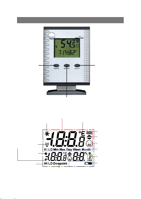
8. Controls and indicators
Key T1
„SENSOR”
Receiving check
of the wireless
sensor
Frost warning
Display panel B
Temperature
alarm
Frost warning
Dewpoint indicator
Key T3
„SELECT”
Key T2
„MIN MAX”
Display panel A
Unit of temperature
Water symbol
Tendency indicator
Comfort indicator
Status indicator
Sensor address
Low battery
warning
Page 11

Description of the used symbols
Frost warning The temperature at the location of the displayed
Unit Alternatively display in ˚F or ˚C
Water symbol Appears only by receiving the outdoor sensors
Tendency indicator Temperature tendency: rising or falling
Comfort indicator In display panel A:
Comfort range, only depends on temperature
(see chapter 10)
In display panel B:
Comfort range, depends on temperature and air
Status indicator Marking of actual display-functions
Sensor address Shows number (address) of the displayed outdoor
Battery warning Low battery warning of the base station
Dewpoint indicator Indicate the dewpoint (alternatively to temperature,
Temperature alarm Indicator for excessing the upper (HI) respectively
Receiving check Marking of correct receiving the particular outdoor
sensor is below 39.2˚F / +4˚C
with the address 1...8, appears not at displaying
the indoor temperature or the combined sensor
(Address 9)
humidity (see chapter 17)
sensor
only for display panel B)
lower (LO) limit value of the temperature
sensor
11
Page 12

12
9. Operation
After Installation accordingly chapter 7 the base station is ready for
operation with the essential functions. You can operate it accordingly
the following operation instructions.
If you want to use the extended functions, please configure the unit
like described in chapter 10.
9.1. Functions of the keys
Main functions
Key Description Main function
T1 SENSOR Choice of sensors
T2 MIN MAX Displaying of the Min/Max values
T3 SELECT Switch for temperature/dewpoint; ˚F/˚C
Basic operation
You can operate the unit with the three keys via short or long keystrokes:
• Short keystroke: Press for shorter than 1 second (et sqq.: ”short”)
• Long keystroke: Press for more than 3 seconds (et sqq.: ”long”)
If you don´t press any key for 10 seconds during the configuration (see
chapter 10), the unit goes back to normal mode, but the last adjustment
remains in the display
9.2. Selecting of the sensors to display
• For allocation and configuration of the sensor addresses
F
please read the manual of the concerned sensor.
•
The combination sensor KS 200US/KS 300US have a fixed
address, he is always displayed with address ”9”.
• At displaying the integrated sensor no address is indi-
cated.
9.2.1. Display panel A - Pool sensor
The display panel A is usually intended for displaying the
F
values of the pool sensor S 300PT-US.
If required, or, when you not use a
allocate any sensor to this panel.
S 300PT-US
, you can
Page 13

- To choose another sensor, press the key ”SENSOR” long till the display in the display panel B disappears and at right the symbol for the
sensor address is blinking.
- Now press the key ”SENSOR” frequently short, till the required sensor
address and in display panel A the data of this sensor is displayed.
- If you don´t press any key for 10 seconds or shortly press the key
”MIN/MAX” or ”SELECT”, the device goes back to normal mode.
Now the data of display panel B appears again (indoor sensor or the
selected outdoor sensor).
•
You can only choose active sensors, that means, the base station
must already received data from this sensor at earlier time. The
F
9.2.2. Display panel B - Indoor or outdoor sensor
F
- For choosing a sensor, press the key ”SENSOR” frequently short, till the
F
unit skips not occupied addresses.
•
By choosing sensors 1...8 the water symbol appears.
•
By choosing the combination sensor the sensor address ”9” appears.
•
By choosing the indoor sensor no sensor address appears.
In the base setting the panel B shows the indoor temperature and the indoor air humidity.
If required, you can allocate any sensor to this panel.
required sensor address and in display panel B the data of this sensor
is displayed.
•
You can only choose active sensors, that means, the base station
must already received data from this sensor at earlier time. The
device skips not occupied addresses.
•
By choosing the combination sensor the sensor address ”9” appears.
•
By choosing the indoor sensor no sensor address appears.
• If the device is still in the selection mode for display panel A,
please wait either, till the panel B is displayed again, or press
the key ”SENSOR” long, till display panel B appears again.
Now the sensor selection for display panel B is activated.
13
Page 14

14
9.3. Displaying MIN/MAX values
For the measurement values of the indoor/outdoor temperature and indoor/outdoor humidity, the minimum and maximum figures reached since
the last clearance (reset) of data are stored.
Accessoy you can call the MIN/MAX values of the sensor, which is assigned
to display panel A, within MIN/MAX values of the last day (24 hours, ”Day”),
the last week (7 days, ”Week”) and the last month (30 days, ”Month”).
If you assign another sensor to display panel A, the stored MIN/
MAX values of the previously assigned sensor are deleted! The
storage begins new from the moment of the new assignment!
If you have selected ”Dewpoint” for display panel B, then the
storage of the MIN/MAX values occurs as dewpoint!
F
- Press the key ”MIN/MAX frequently short, till the required value appears.
The sequences of the display panels A and B:
Sequence of display panel A
(Pool sensor)
1
MIN value since reset MIN value since reset
2
MAX value since reset MAX value since reset
3
MIN value last day (Day) MIN value since reset
4
MAX value last day (Day) MAX value since reset
5
MIN value last week (Week) MIN value since reset
6
MAX value last week (Week) MAX value since reset
7
MIN value last month (Month) MIN value since reset
8
MAX value last month (Month) MAX value since reset
9
Current value Current value
Sequence of
display panel B
Page 15

• While retrieving the MIN-/MAX values for display panel A, also
F
Deleting MIN-/MAX values
F
- Press the key ”MIN MAX” long.
- The hole display disappears, after this ”rEs” appears for approx.
- After this the display goes to the normal mode before clearance.
The current values are immediately taken over as the new MIN-/MAX
9.4. Selecting temperature metered value (Temp./Dewpoint)
For the reading in display panel B you can switch between displaying
Change between temperature and dewpoint
9.5. Frost warning
The frost warning is always active. This function warns, if the temperature
of the sensor, which is displayed in the particular display panel, is below
39.2˚F.
First time after temperature is below 39.2˚F, the frost warning symbol
in the according display panel is blinking for 30 seconds, after this the
frost warning symbol remains on permanently.
the display panel B respectively changes between MIN- and
MAX value, but only the MIN-/MAX values since last clearance
(reset) are displayed!
• After choosing a storage display (MIN-/MAX value), you can
successive call the particular extreme value of all sensors into
display panel B by pressing the key ”SENSOR” frequently
short.
• The device goes back to the display of current value after ”MAX
value last month” in display panel A.
All stored MIN-/MAX values of all sensors will be deleted together!
2 seconds.
values.
the temperature and the associated dewpoint.
- Press the key ”SELECT” shortly. Temperature value in display panel
B changes between temperature and dewpoint. At dewpoint choice
accessorily ”Dewpoint” appears in the display.
15
Page 16

16
Frost warning is turned off after the temperature exceeds the value of
41°F.
If required, you can add the frost warning with an audible warning (how
to activate, see chapter 10.3).
• The alarm value of 39.2˚F is fixed and not adjustable.
F
• The frost warning is only active for the displayed sensors
(in display panel A and B), that means, if the temperature of
not displayed sensors fall below 39.2˚F, no alarm will be activated.
9.6. Activate temperature alarm
For any sensor you can set up high and/or low temperature limit. If the
temperature exceeds this high or low temperature limit, the temperature
alarm is activated.
• Status indicator ”HI”: upper temperature limit is exceeded
• Status indicator ”LO”: lower temperature limit is fallen short
Are the limits occupied with values according chapter 10.2, the temperature alarm is automatically activated.
If you want to deactivate the alarm, you have to set the limit to ”--.-“ (see
Chapter 10.2).
If required, you can add the temperature alarm with audible warning (how
to enable, see chapter 10.3).
• The temperature alarm is only active for the displayed sen-
F
9.7. Switch off audio warning during alarm
- Press any key, the audible warning turns off immediately.
F
sors (in display panel A and B), that means, if the temperature
of not displayed sensors is below or higher than this limits, no
alarm will be activated.
The function of audio warning remains also after turning off.
The buzzer is blocked, till the reason of the alarm is eliminated for minimum one measuring. If eg. the frost warning
permanent exists, the buzzer doesn`t sounds after the next
temperature measuring of the particular sensor. Only if the
reason of the alarm does not longer exists (frost warning or
temperature alarm) for minimum one measuring value, the
audio alarm is enabled again.
Page 17

10. Configuration
SELECT
> 3 seconds
10.1. Selecting temperature unit
The temperature unit can be switched between
displaying in ˚F or ˚C.
°F/˚C switching
-
Press the key ”SELECT” for approx.
3 seconds. In both display panels
changes
from ˚F to ˚C and vice versa.
the unit
10.2. Setting the temperature alarm
values (limits)
For any sensor you can set-up a high and/or
low temperature limit. If the limit is exceeded, a temperature alarm is activated.
•
In factory setting the temperature
alarm is disabled (no limits set).
F
• The adjustable range is (independent
of the sensor type) -21.8˚F up to
+175.8˚F. Consider the measuring
limits of the particular sensor when
setting the alarm limits.
• If you want adjust only high or low
limit, set the particular other limit to
”– – .– ” (disabled). This setting follows the value ”+175.8˚F”.
•
The temperature alarm is only active
for the displayed sensors (in display
panel A and B), that means, if the
temperature of not displayed sensors
is below or higher than this limits, no
alarm will be activated.
17
Page 18

18
SENSOR
> 3 seconds
resp.
SELECT
SENSOR
> 3 seconds
resp.
MIN MAX
+
+
MIN MAX
Set
value
MIN MAX
Adjust low temperature alarm limit
- Press the keys ”SENSOR” and ”MIN MAX”
together for approx. 3 seconds.
- Now the low limit of the sensor, which was
assigned to the display panel A, and the
symbol ”LO” appears.
- If you want to adjust the low limit of one
of the other sensors, press the key ”SENSOR” frequently short, till the required
sensor address appears in display panel B.
In factory setting are no limits preset
this is marked with ”– – .–”.
F
- Adjust the required value for the low limit
by pressing the key ”SELECT” frequently
(shortly or continued).
- Go ahead with adjusting resp. checking
the high limit.
Adjust high temperature alarm limit
- Press the keys ”SENSOR” and ”MIN MAX”
together for approx. 3 seconds.
- Now the low limit of the sensor, which was
assigned to the display panel A, and the
symbol ”LO” appears.
- If you want to adjust the limit of one of the
other sensors, press the key ”SENSOR”
frequently short, till the required
address appears in display panel B
- Now press the key ”MIN MAX” shortly. The
status indicator changes to ”HI”.
sensor
,
Page 19

SELECT
SENSOR
Set
value
Back to
normal mode
In factory setting are no limits preset
this is marked with ”– – .–”.
F
- Adjust the required value for the high limit
by pressing the key ”SELECT” frequently
(shortly or continued).
- Go back to the normal mode by pressing
the key ”SENSOR” frequently short
or,
wait without any keystroke, till the device
goes back to the normal mode.
Disable temperature alarm
Adjust the temperature limit of the particular
sensor to ”– –.–” (follows after ”+175.8˚F”).
,
19
Page 20

20
SELECT
> 3 seconds
SELECT
> 3 seconds
+
+
MIN MAX
MIN MAX
10.3. Enable/Disable
the audio warning
The integrated buzzer generates an audio
warning, if the audio warning option is enabled
and a frost warning or a temperature alarm is
triggered. If alarm is triggered first time, the audio warning sounds for 30 seconds, thereafter
in the rhythm of 30 Seconds for respectively
approx. 3 seconds. The audio warning will be
enabled/disabled together for all sensors.
Enable audio warning
- Press the keys ”SELECT” and ”MIN MAX”
together for approx. 3 seconds.
- The display disappears shortly and thereafter ”ON” appears in both display panels.
Thereafter the device goes back to the
normal mode.
Disable audio warning
- Press the keys ”SELECT” and ”MIN MAX”
together again for approx. 3 seconds.
-
The display disappears shortly and thereafter ”OFF” appears in both display panels.
Thereafter the device goes back to the
normal mode.
Page 21

SENSOR
> 3 seconds
SELECT
+
SELECT
value
10.4. Setting the comfort tempera-
ture range of display panel A
The display panel A is usually intended for displaying the values of the pool sensor S300PT-US.
You can set an individual temperature range,
which shall feel as comfortable.
The comf or t symbol in display p anel A
shows, that the temperature is within the
required range. The comfort range is defined by the adjustable high and low limits
of temperature.
The meanings of the comfort indicator:
J Temperature is within the comfort range
K Temperature is less than
comfort range.
L Temperature is more than
the comfort range.
3.6°F beyond the
3.6°F beyond
• The factory setting of the comfort
F
- Press the keys ”SENSOR” and ”SELECT”
-
The display shows the previous low limit of
- Adjust the required value for the low limit
Set
range is from 77˚F to 82.4˚F.
• The adjustable range is (inde-
pendent of the sensor) 41˚F up to
158˚F. Consider the measuruing
limits of the particul ar sens or
when setting the comfort range.
together for approx. 3 seconds.
the comfort range, the comfort symbol
and ”LO” in panel A.
by pressing the key ”SELECT” frequently
(short or continued).
J
21
Page 22

22
MIN MAX
SELECT
SENSOR
Change
to HI
Set
value
Back to
normal mode
- Thereafter press the key ”MIN MAX”
shortly. The status indicator changes to
”HI”.
- Adjust the required value for the high limit
by pressing the key ”SELECT” frequently
(short or continuing).
- Go back to the normal mode by pressing
the key ”SENSOR” frequently short
or,
wait without any keystroke, till the device
goes back to the normal mode.
Page 23

11. Other functions and settings
11.1. Commissioning of new sensors
You can add new sensors into the system at anytime.
Consider the maximum number of 9 radio sensors (incl. combined sensor)
and avoid double addressing.
• The automatic apply of new sensors is carried out two times a day (at
intervals of 12 hours) during a regular transmitter search.
• You can also assimilate new sensors by commissioning the base station
once again.
In this case consider:
The device is setting back to the factory settings, all stored datawill
be deleted!
11.2. Reset to factory setting
The factory setting is:
• Display panel A: Pool sensor or other sensor with address 8
• Display panel B: Indoor sensor
• No alarm limits set
• Comfort range at display panel A: 77˚F to 82.4˚F.
• Audio warning: turned off
- Open the battery compartment, remove the batteries and insert the
batteries again with the correct polarity.
- All user settings will be set to the factory setting.
- All stored MIN-/MAX data will be deleted.
- The device starts now like described in chapter 7
.
11.3. Receiving indicator
- If the selected sensor is received, the antenna symbol (see above) ap-
pears constant.
- If the device can´t receive the selected sensor for more than 40 minutes,
the antenna symbol blinks.
- If the device can`t receive this sensor for more than 12 hours, the antenna
symbol disappears and the associated value is displayed as ”- - .-”.
23
Page 24

24
11.4. Frost warning
This function warns, if the temperature of the sensor, which is displayed in the
particular display panel, is below 39.2˚F/+4˚C (see more in chapter 9.5). In the
particular display panel the frost warning symbol (see above) appears.
12. Changing battery
Depending on which batteries or rechargeable batteries you
F
12.1. Base station
If the battery flat symbol appears in the display ( ), the batteries have
to be replaced with new ones.
F
12.2. Combination sensor, outdoor sensors, pool sensor
When the display of the sensor concerned fails for more than 24 hours,
the batteries are to be replaced with new ones as described in the particular manual.
F
use, the replacement interval can be very different. High-quality
alkaline batteries keep the longest, rechargeable batteries or
cheap zinc-carbon batteries require more frequent changing.
• Always replace the whole set of batteries.
• Do not mix full with “half-full” batteries.
• Always use four batteries of the same type and manufacturer.
• Do not mix batteries with rechargeable batteries.
• As already mentioned, rechargeable batteries operation is possible, the durability is, however, appreciably lower than with
batteries.
•
For changing the batteries, proceed as described in chapter 7. 1.
Please observe the following:
After replacing the batteries, all data, values stored in the base
station (e.g. settings, MIN-/Max data etc.) are deleted and have
to be entered again.
Check as whether there is possibly some disturbance in the
radio transmission which is the cause for the failure of the data
transmission. In this case also, there will be no indication in
the display of the base station.
The cause could be, for example, a metal object in the radio
path (e.g., a parked vehicle).
Page 25

13. Trouble shooting
Observe the safety instructions contained in these
operating instructions!
Problem Remedy
No reception
Disturbance of
other instruments
through the
outdoor sensors
• The distance between the base station and outdoor sensors is too great. Alter the position of the
outdoor sensors.
• Objects or shielding materials are obstructing the
radio reception. Alter the position of the outdoor
sensors and the base station.
• The batteries of the outdoor sensors are too weak
or flat. Insert new batteries into the sensors as
an attempt.
• Another transmitter on the same or neighboring
frequencies is disturbing the radio signal of the
outdoor sensors. This can be, for example, radio
headphones, radio loudspeakers or similar devices.
Such products are not usually operated constantly;
the radio reception can, for example, be perfect
the next day; this makes the search for the cause
more difficult.
If possible, set another frequency on the instru-
ments which can eliminate the reception problems
of the weather station.
• The outdoor sensors transmit their data to the base
station approx. every 3 minutes for a period of 0.1
(100 ms) seconds. In this short period, disturbances
in other devices are also possible.
For example, a very short disturbance signal can
be audible from a radio head phone every 3 minutes.
(continuation see next page)
25
Page 26

26
Problem Remedy
Problems with the
Synchronisation
• When inserting the batteries into the outdoor
sensors and the base station (observe this order
exactly), these devices are in synchronization
mode. A data telegram is transmitted here every
4 seconds which accelerates the recognition
and registration of the outdoor sensors at the
base station.
To enforce new synchronization, remove the
batteries from the base station and outdoor
sensors. After that, wait at least 60 seconds
before you insert the batteries into the outdoor
sensors again and, lastly, into the base station
(observe this order without fail – first of all insert
the batteries into all existing outdoor sensors,
only then into the base station.
In doing so, however, all values/data which the
base station has stored (e.g. minimum values,
maximum values and settings etc.), are lost.
• Before you position the outdoor sensors, for
example in your garden, carry out a function
test as described in chapter 7.
Page 27

14. Range
The transmission range of the radio signals to the base station is
300 ft. under optimum conditions. This is often described as the “free
field range”.
This ideal arrangement (e.g. base station and outdoor sen-
F
Normally, the base station is set up in the house, the combination in the
garden and further outdoor sensors, for example in ancillary buildings
or garage.
The range can be reduced considerably partly through:
• walls, reinforced steel ceilings
• coated/layered insulation glass panes
• vehicles
• trees, bushes, earth, rocks
• closeness to metal & conductive objects (e.g. radiators)
• closeness to the human body
• broadband disturbances, e.g. in residential area (DECT telephones,
• closeness to electric motors. Transformers, network parts pr com-
• closeness to poorly shielded or openly operated computers or other
F
sor on a smooth, level field without trees, houses etc.) is,
however, never found in practice.
mobile telephones, radio head-phones, radio loudspeakers, other
radio weather stations, baby phones etc.)
puters
electrical devices
As the local circumstances are different at every place of set-up,
a certain range cannot be guaranteed.
If the base station is receiving no data from the combination
sensor or any additionally existing outdoor sensors (in spite of
new batteries), reduce the distance between the outdoor sensors
and the base station, change the place of set-up
Observe chapter 7 and 13 of these operating instructions..
27
Page 28

28
15.Maintenance and cleaning
15.1. General
Check the technical safety of the product regularly, e.g. damage to the
housing.
It can be assumed that operation is no longer ensured without risk if
• the device shows visible damage
• the device is no longer functional
• after longer periods of storage under unfavorable conditions or
• after heavy transport stress
Before cleaning or servicing the device, observe the following safety
instructions without fail:
Remove the batteries before cleaning, servicing or carrying
out repair work.
There are no parts in the interior requiring servicing; the device
may not be opened.
Repairs may only be carried out by a specialist who is familiar
with the associated hazards and relevant regulations for the
device.
15.2. Cleaning base station
Dust can be removed very easily with a vacuum cleaner and a clean, soft
brush. Keep the opening of the vacuum cleaner close to the base station
(do not come into contact, scratching possible!) and remove the dust with
the brush. The dispersed dust will be sucked in by the vacuum cleaner.
Use a soft, dry, lint-free cloth for cleaning the exterior of the product.
For greater contamination, you can use a cloth slightly moistened with
warm water.
Never use aggressive cleaners or chemical solutions as the surface of the
device or its functionality could be damaged as a result.
Page 29

16. Handling
Observe all the safety precautions in these operating
instructions!
16.1. General
The product may not be opened or taken apart (except for the work described in these operating instructions, e.g. change of battery).
There are no parts to be maintained by the user in the inside of the
product.
The product will be damaged even if dropped from a low height.
16.2. Base station
Avoid the following adverse ambient conditions during operation or
transport:
- moisture or excessive humidity
- extreme cold or heat direct sunlight
- dust or flammable gases, vapours or
- heavy vibration
- strong magnetic fields, such as, for example, in the vicinity of machines or speakers
Never use the product immediately if it has been taken from a cold area
to a warm area. The condensation developing could in certain cases
destroy the device.
Wait until the base station has reached room temperature. This can
take some hours!
A place for set-up has to be selected so that the base station stands
securely and cannot fall down. There is danger of injury due to its extreme
heaviness.
Valuable or easily scratched furniture surfaces should be protected from
damage by suitable mats before setting up the base station.
29
Page 30

30
17. Terminology
17.1. Comfort indicator (only display panel B)
The symbol of the comfort indicator (the three different “smiles“ J K L )
reflect the room climate whereby the weather station works according to
the following table:
Temperature air humidity (%)
20 30 35 40 45 50 55 60 65 70
< 64,4°F L L L L L L L L L L
64.4-67.9°F L L L K K K K K K L
68.0-71.5°F L L L K J J J J K L
71.6-75.1°F L L K J J J J K L L
75.2-78.7°F L K J J J J K L L L
78.8-82.3°F L K K K K K K L L L
over 82.4°F L L L L L L L L L L
Dependent of the ratio temperature to humidity, there are clearly delimited
areas which are defined as comfortable or uncomfortable climate.
For example, you feel humidity of under 30% to be too dry at a temperature of 77° F (e. g. heating air) and humidity of over approx. 60% to be
humid.
• The comfort indicator in display panel A is controlled according
F
to the defined comfort temperature range (see chapter 10.4.)
• For sensors, which don´t transmit air humidity values, the
display don´t show the comfort indicator.
17.2. Dewpoint
This concerns a temperature which is dependent on the coincidence of a
certain temperature and a certain humidity.
The condensation of the humidity begins at this temperature point, the
humidity condenses and comes down as liquid (mist, vapour).
If the dewpoint for water vapour lies at below 32° F, condensation will take
place as snow or frost.
Page 31

18. Disposal
18.1. General
Dispose of the unusable product according to valid legal regulations
19. Specifications
Temperature range indoors: .................. 32°F to 140°F (0°C to +59.9°C)
Resolution: .................................................................................... 0.1 °F
Accuracy: ....................................................................................±1.4 °F
Measurement range rel. humidity indoor: ..............................0 % - 99 %
Resolution: .......................................................................................1 %
Accuracy: ..............................................................±5 % (30 % to 70 %)
Measuring interval of the indoor sensor: ...............................10 minutes
Number of external sensors: ......................................................... max. 9
Transmission interval of the outdoor sensors:.............approx. 3 minutes
Transmission frequency: ....................................................... 433.92 MHz
Range in the free field:................................ up to 300 ft (see chapter 14)
Dewpoint displaying: ....... for sensors with temperature and air humidity
Frost warning: ......................... at temperatures ≤39.2°F/+4˚C, automatic
Temperature alarm:
......................................................for every sensor, threshold adjustable
Comfort indicator ..............................for both display panels separately,
....................................... comfort temperature range for the pool sensor
......................................................... (or other with address 8) adjustable
Voltage supply: .......................................3 x 1.5 V AA/LR6/Mignon cells
Environment temperature range: .................................... 32 °F to 122 °C
Display viewing area (w x l): ..............................................2.2 x 1.6 inch
Dimension (w x l x d):
.................................................................4.1 x 5.7 x 2.2 inch (with base)
............................................................. 4.1 x 5 x 1.3 inch (without base)
31
Page 32

20. FCC information
FCC ID: RNT-PTD300US
Changes or modifications not expressly approved in writing by eQ-3
Limited may void the user‘s authority to operate the equipment.
NOTE: This equipment has been tested and found to comply with the
limits for a Class B digital device, pursuant to Part 15 of the FCC Rules.
These limits are designed to provide reasonable protection against harmful
interference in a residential installation. This equipment generates, uses
and can radiate radio frequency energy and, if not installed and used in
accordance with the instructions, may cause harmful interference to radio
communications. However, there is no guarantee that interference will not
occur in a particular installation. If this equipment does cause harmful
interference to radio or television reception, which can be determined by
turning the equipment off and on, the user is encouraged to try to correct
the interference by one or more of the following measures:
- Reorient or relocate the receiving antenna.
- Increase the separation between the equipment and receiver.
- Connect the equipment into an outlet on a circuit different from that to
which the receiver is connected.
- Consult the dealer or an experienced radio/TV technician for help.
The internal antenna used for this mobile transmitter must provide a
separation distance of at least 20 cm from all persons and must not
be co-located or operating in conjunction with any other antenna or
transmitter.
This device complies with Part 15 of the FCC Rules. Operation is subject
to the following two conditions:
(1) this device may not cause harmful interference, and
(2) this device must accept any interference received, including interfe-
rence that may cause undesired operation.
1st English edition October 2006
Documentation © 2006 eQ-3 Limited Hongkong
All rights reserved. This handbook must not be reproduced in any form, even in excerpts,
or duplicated or processed using electronic, mechanical or chemical procedures without
written permission of the publisher.
This handbook may contain mistakes and printing errors. The information in this
handbook is regularly checked and corrections made in the next issue. We accept no
liability for technical mistakes or printing errors, or their consequences. All trademarks
and patents are acknowledged.
Printed in Hong Kong
Modifications due to technical improvements may be made without prior notification.
00066789 Y2006 V1.0
32
 Loading...