

Epson UB-E01 Other Documents
UB-E01 User’s Manual
Copyright © 1999 SEIKO EPSON CORPORATION
Introduction
The UB-E01, designed for EPSON TM printers, is a 10BASE-T Ethernet
interface board.
This manual provides instructions for operators of POS systems in which the
UB-E01 is installed so that the operators can use the UB-E01 safely and
correctly. For information about installation and settings required, see the
UB-E01 Developer’s Guide. To get the UB-E01 Developer’s Guide, contact
your EPSON representative or your place of purchase.
Key to Symbols
The symbols in this manual are identified by their level of importance, as
defined below. Read the following carefully before handling the product.
CAUTION:
Observe cautions to avoid minor injury to yourself, damage to your
equipment, or loss of data.
401209601
Note:
Notes have important information and useful tips on the operation of your equipment.
1
Caution Label
The following caution label is visible near the display module connector.
The label has the following meaning:
“The display module connector and the drawer kick-out connector use the
same type of the Ethernet connector; therefore, be sure not to connect the
Ethernet connector cable or the telephone line to the display module connector
or the drawer kick-out connector.”
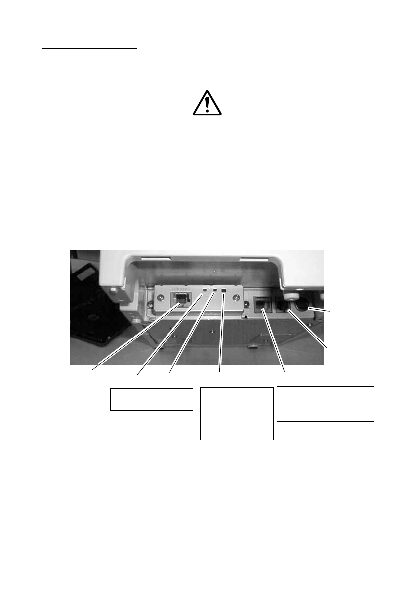
Part Names
The following view shows the part names of the UB-E01.
Power supply
connector
Drawer kickout
connector
10BASE-T Ethernet
interface
connector
Note: This photograph shows the TM-H6000 printer with the UB-E01 installed.
LED (green) LED (red)
Be sure not to push the
LEDs by accident
Switch
If you press and hold
this switch when the
printer is on, the
interface will be
reset to the factory
settings
2
Display module connector
The display module
connector on the TM printer
cannot be used when the
UB-E01 is installed.
 Loading...