

Page 1

Confidential
EPSON
TM-T88III series
Receipt Printer
Specification
Rev. No. B
Notes
Copied Date , ,
Copied by
SEIKO EPSON CORPORATION
STANDARD
MATSUMOTO MINAMI PLANT
2070 KOTOBUKI KOAKA, MATSUMOTO-SHI, NAGANO, 399-8702 JAPAN
PHONE(0263)86-5353 FAX(0263)86-9923
Page 2

Confidential
REVISION SHEET
The table below indicates which pages in this specification have been revised.
Before reading this specification, be sure you have the correct version of each page.
Revisions Design Section Sheet Rev. No.
Rev. Document WRT CHK APL Sheet Rev. Sheet Rev. Sheet Rev.
Sheet 1 of 4
A Enactment
B Change
Nakayama -- Omura
I
II
III
IV
V
VI
B 17 B 42 B
B 18 B 43 B
B 19 B 44 B
B 20 B 45 B
B 21 B 46 B
B 22 B 47 B
23 B 48 B
24 B 49 B
25 B 50 B
1 B 26 B 51 B
2 B 27 B 52 B
3 B 28 B 53 B
4 B 29 B 54 B
5 B 30 B 55 B
6 B 31 B 56 B
7 B 32 B 57 B
8 B 33 B 58 B
9 B 34 B 59 B
10 B 35 B 60 B
11 B 36 B 61 B
12 B 37 B 62 B
13 B 38 B 63 B
14 B 39 B 64 B
15 B 40 B 65 B
16 B 41 B 66 B
TITLE
TM-T88III series
Specification
(STANDARD)
Front Part
Cover
Rev.
Sheet
Confidentiality
Agreement
General
Features
Table of
Contents Contents Appendix
1 4 1 1 4 152 20 183
Total
Page 3

Confidential
REVISION SHEET
The table below indicates which pages in this specification have been revised.
Before reading this specification, be sure you have the correct version of each page.
Revisions Design Section Sheet Rev. No.
Rev. Document WRT CHK APL Sheet Rev. Sheet Rev. Sheet Rev.
Sheet 2 of 4
A Enactment
B Change
67 B 92 B 117 B
68 B 93 B 118 B
69 B 94 B 119 B
70 B 95 B 120 B
71 B 96 B 121 B
72 B 97 B 122 B
73 B 98 B 123 B
74 B 99 B 124 B
75 B 100 B 125 B
76 B 101 B 126 B
77 B 102 B 127 B
78 B 103 B 128 B
79 B 104 B 129 B
80 B 105 B 130 B
81 B 106 B 131 B
82 B 107 B 132 B
83 B 108 B 133 B
84 B 109 B 134 B
85 B 110 B 135 B
86 B 111 B 136 B
87 B 112 B 137 B
88 B 113 B 138 B
89 B 114 B 139 B
90 B 115 B 140 B
91 B 116 B 141 B
TITLE
TM-T88III series
Specification
(STANDARD)
Front Part
Cover
Rev.
Sheet
Confidentiality
Agreement
General
Features
Table of
Contents Contents Appendix
1 4 1 1 4 152 20 183
Total
Page 4
Confidential
(
REVISION SHEET
The table below indicates which pages in this specification have been revised.
Before reading this specification, be sure you have the correct version of each page.
Revisions Design Section Sheet Rev. No.
Rev. Document WRT CHK APL Sheet Rev. Sheet Rev. Sheet Rev.
Sheet 3 of 4
A Enactment
142 B App.1 B
B Change 143 B App.2 B
144 B App.3 B
145 B App.4 B
146 B App.5 B
147 B App.6 B
148 B App.7 B
149 B App.8 B
150 B App.9 B
151 B App.10 B
152 B App.11 B
App.12 B
App.13 B
App.14 B
App.15 B
App.16 B
App.17 B
App.18 B
App.19 B
App.20 B
TITLE
TM-T88III series
Specification
STANDARD)
Front Part
Cover
Rev.
Sheet
Confidentiality
Agreement
General
Features
Table of
Contents Contents Appendix
1 4 1 1 4 152 20 183
Total
Page 5

Confidential
REVISION SHEET
REV. SHEET CHANGED CONTENTS
B
All All pages are revised, due to addition of the multilingual support.
II GENERAL FEATURES
The following models are available … (added)
III - VI Table of Contents (changed)
1 – 3 1.1 Printing Specifications
1.2 Character Specifications
Description for Kanji and Thai characters support (added)
25 2.1.4 Other interfaces (added)
31 Kanji command list (added)
42 - 50 3.2.11 Page 20 through 3.2.17 Page 26 (added)
3.2.11 → 3.2.18, 3.2.12 → 3.2.19
66 5.1 Standard Accessories
User’s manual (Languages: .. Simplified Chinese, Traditional Chinese) (added)
77 ESC !
[Details] • Emphasized mode is … (added)
86 ESC -
[Details] • This command does not … (added)
106 ESC t
[Range] [Description] [Default] Thai model (added)
123 GS I
[Range] [Description] n=69 (added)
145 -
152
App.1 Table A.1 Kanji font (added)
App.20 APPENDIX K, Multilingual support (changed)
6.4 Kanji Control Commands (added)
Sheet 4 of 4
TITLE
TM-T88IIIIIIIIIIII series
Specification
(STANDARD)
Page 6

Confidential
CONFIDENTIALITY AGREEMENT
BY USING THIS DOCUMENT, YOU AGREE TO ABIDE BY THE TERMS OF THIS AGREEMENT. PLEASE
RETURN THIS DOCUMENT IMMEDIATELY IF YOU DO NOT AGREE TO THESE TERMS.
1. This document contains confidential, proprietary information of Seiko Epson Corporation or its affiliates.
You must keep such information confidential. If the user is a business entity or organization, you must
limit disclosure to those of your employees, agents, and contractors who have a need to know and who
are also bound by obligations of confidentiality.
2. On the earlier of (a) termination of your relationship with Seiko Epson, or (b) Seiko Epson's request, you
must stop using the confidential information. You must then return or destroy the information, as
directed by Seiko Epson.
3. If a court, arbitrator, government agency, or the like orders you to disclose any confidential information,
you must immediately notify Seiko Epson. You agree to give Seiko Epson reasonable cooperation and
assistance in the negotiation.
4. You may use confidential information only for the purpose of operating or servicing the products to which
the document relates, unless you obtain the prior written consent of Seiko Epson for some other use.
5. Seiko Epson warrants that it has the right to disclose the confidential information. SEIKO EPSON
MAKES NO OTHER WARRANTIES CONCERNING THE CONFIDENTIAL INFORMATION OR ANY
OTHER INFORMATION IN THE DOCUMENT, INCLUDING (WITHOUT LIMITATION) ANY
WARRANTY OF TITLE OR NON-INFRINGEMENT. Seiko Epson has no liability for loss or damage
arising from or relating to your use of or reliance on the information in the document.
6. You may not reproduce, store, or transmit the confidential information in any form or by any means
(electronic, mechanical, photocopying, recording, or otherwise) without the prior written permission of
Seiko Epson.
7. Your obligations under this Agreement are in addition to any other legal obligations. Seiko Epson does
not waive any right under this Agreement by failing to exercise it. The laws of Japan apply to this
Agreement.
Cautions
1. This document shall apply only to the product(s) identified herein.
2. No part of this document may be reproduced, stored in a retrieval system, or transmitted in any form or
by any means, electronic, mechanical, photocopying, recording, or otherwise, without the prior written
permission of Seiko Epson Corporation.
3. The contents of this document are subject to change without notice. Please contact us for the latest
information.
4. While every precaution has been taken in the preparation of this document, Seiko Epson Corporation
assumes no responsibility for errors or omissions.
5. Neither is any liability assumed for damages resulting from the use of the information contained herein.
6. Neither Seiko Epson Corporation nor its affiliates shall be liable to the purchaser of this product or third
parties for damages, losses, costs, or expenses incurred by the purchaser or third parties as a result of:
accident, misuse, or abuse of this product or unauthorized modifications, repairs, or alterations to this
product, or (excluding the U. S.) failure to strictly comply with Seiko Epson Corporation's operating and
maintenance instructions.
7. Seiko Epson Corporation shall not be liable against any damages or problems arising from the use of
any options or any consumable products other than those designated as Original EPSON Products or
EPSON Approved Products by Seiko Epson Corporation.
Trademarks
EPSON® and ESC/POS® are registered trademarks of Seiko Epson Corporation.
General Notice: Other product and company names used herein are for identification purposes only and may
be trademarks of their respective companies.
EPSON
TITLE
TM-T88III series
Specification
(STANDARD)
SHEET
REVISION
B
NO.
SHEETNEXT
III
Page 7

Confidential
GENERAL FEATURES
This specification applies the following models of the TM-T88III series printer:
TM-T88III (with serial interface (*1))
TM-T88IIIP (with parallel interface)
The following models are available for each product above.
1) Alphanumeric (ANK) model
2) Multilingual model (*)
3) Japanese model
(*): The multilingual character model supports printing with one of the following characters:
➀ Simplified Chinese
➁ Traditional Chinese
➂ Thai
➃ Korean
The printer has the following features:
1) Printing
• High speed printing: approximately 35.5 lps (4.23 mm {1/6"} feed) maximum. [lps: lines per second]
• Low-noise thermal printing.
• High reliability due to a stable mechanism.
2) Application Software
£
• Command protocol is based on the ESC/POS
• Various Layouts are possible by using page mode.
• Characters can be scaled up to 64 times as large as the standard size. Smoothing is also possible.
• Bar code printing is possible by using a bar code command. Bar codes can be printed both in the
vertical direction (fence bar code) and in the horizontal direction (ladder bar code) (*2).
• Repeated operation and copy printing are possible by using macro definitions.
• Character font size (12 × 24 font or 9 × 17 font) can be selected using a command.
3) Printer Handling
• Easy paper roll setting.
• Equipped with an autocutter.
• The printer allows easy maintenance for tasks such as head cleaning.
• Three different print densities can be selected by DIP switches.
• The built-in interface provides control capability for two drawers.
NOTES) *1: An RS-485 serial interface is a factory option.
*2: The ladder bar code is effective only in the page mode.
standard.
EPSON
TITLE
TM-T88III series
Specification
(STANDARD)
SHEET
REVISION
B
NO.
SHEETNEXT
IIIII
Page 8

Confidential
Table of Contents
1. GENERAL SPECIFICATIONS
1.1 Printing Specifications.................................................................................................................. 1
1.2 Character Specifications ..............................................................................................................2
1.3 Autocutter..................................................................................................................................... 3
1.4 Paper Roll Supply Device............................................................................................................. 4
1.5 Paper Specification ...................................................................................................................... 4
1.6 Printable Area............................................................................................................................... 5
1.7 Printing and Cutting Positions ...................................................................................................... 6
1.8 Internal Buffer...............................................................................................................................6
1.9 Electrical Characteristics..............................................................................................................7
1.10 EMI and Safety Standards Applied.............................................................................................7
1.11 Reliability....................................................................................................................................8
1.12 Environmental Conditions .......................................................................................................... 8
1.13 Installation.................................................................................................................................. 9
2. CONFIGURATION
2.1 Interface .....................................................................................................................................10
2.1.1 RS-232 serial interface ....................................................................................................... 10
2.1.2 IEEE 1284 Bidirectional Parallel Interface .......................................................................... 15
2.1.3 RS-485 Serial Interface....................................................................................................... 21
2.1.4 Other Interfaces.................................................................................................................. 25
2.2 Connectors................................................................................................................................. 26
2.2.1 Interface Connectors........................................................................................................... 26
2.2.2 Power Supply Connector .................................................................................................... 26
2.2.3 Drawer Kick-out Connector (Modular Connector)............................................................... 27
3. FUNCTIONS
3.1 List of commands....................................................................................................................... 29
3.2 Character Code Tables.............................................................................................................. 32
3.2.1 Page 0 (PC437: USA, Standard Europe) (International Character Set: U.S.A.)................. 32
3.2.2 Page 1 (Katakana)..............................................................................................................33
3.2.3 Page 2 (PC850: Multilingual) ..............................................................................................34
3.2.4 Page 3 (PC860: Portuguese).............................................................................................. 35
3.2.5 Page 4 (PC863: Canadian-French) .................................................................................... 36
3.2.6 Page 5 (PC865: Nordic)...................................................................................................... 37
3.2.7 Page 16 (WPC1252)........................................................................................................... 38
3.2.8 Page 17 (PC866: Cyrillic#2)................................................................................................ 39
3.2.9 Page 18 (PC852: Latin2) .................................................................................................... 40
3.2.10 Page 19 (PC858).............................................................................................................. 41
3.2.11 Page 20 (Thai character code 42) .................................................................................... 42
3.2.12 Page 21 (Thai character code 11) .................................................................................... 43
3.2.13 Page 22 (Thai character code 13) .................................................................................... 44
3.2.14 Page 23 (Thai character code 14) .................................................................................... 45
3.2.15 Page 24 (Thai character code 16) .................................................................................... 46
3.2.16 Page 25 (Thai character code 17) .................................................................................... 47
3.2.17 Page 26 (Thai character code 18) .................................................................................... 48
3.2.18 Page 255 (Space Page).................................................................................................... 49
3.2.19 International Character Set............................................................................................... 50
3.3 Switches and Buttons................................................................................................................. 51
3.3.1 Power Button.......................................................................................................................51
3.3.2 Panel Buttons...................................................................................................................... 51
3.3.3 DIP Switches....................................................................................................................... 52
EPSON
TITLE
TM-T88III series
Specification
(STANDARD)
SHEET
REVISION
B
NO.
SHEETNEXT
IIIIV
Page 9

Confidential
3.4 Panel LED Indicators.................................................................................................................. 55
3.5 Self-test...................................................................................................................................... 56
3.6 Hexadecimal Dumping............................................................................................................... 57
3.7 Error Processing.........................................................................................................................58
3.7.1 Error Types......................................................................................................................... 58
3.7.2 Printer Operation When an Error Occurs ........................................................................... 59
3.7.3 Data Receive Error (only in the serial interface specification) ............................................ 59
3.8 Paper Sensors............................................................................................................................ 59
3.9 Cover Open Button..................................................................................................................... 60
3.10 Cover Open Sensor.................................................................................................................. 60
3.11 Print Buffer-full Printing ............................................................................................................60
3.12 Page Mode............................................................................................................................... 61
3.12.1 General Description .......................................................................................................... 61
3.12.2 Setting Values in Standard and Page Modes ...................................................................61
3.12.3 Formatting of Print Data in the Printable Area .................................................................. 62
4. CASE SPECIFICATIONS
4.1 External Dimensions and Mass.................................................................................................. 65
4.2 Color...........................................................................................................................................65
4.3 External Appearance.................................................................................................................. 65
5. OPTIONS AND CONSUMABLES
5.1 Standard Accessories ................................................................................................................66
5.2 Options....................................................................................................................................... 66
5.3 Consumables .............................................................................................................................66
6. COMMANDS
6.1 Command Notation ....................................................................................................................67
6.2 Explanation of Terms ................................................................................................................. 67
6.3 Control Commands ....................................................................................................................69
HT................................................................................................................................................ 69
LF................................................................................................................................................. 69
FF................................................................................................................................................. 70
CR................................................................................................................................................ 70
CAN .............................................................................................................................................70
DLE EOT n................................................................................................................................... 71
DLE ENQ n .................................................................................................................................. 74
DLE DC4 n m t............................................................................................................................. 75
ESC FF........................................................................................................................................ 76
ESC SP n..................................................................................................................................... 76
ESC ! n......................................................................................................................................... 77
ESC $ nL nH................................................................................................................................78
ESC % n ......................................................................................................................................79
×
ESC & y c1 c2 [x1 d1...d(y
ESC ∗ m nL nH d1...dk ................................................................................................................ 83
ESC - n ........................................................................................................................................86
ESC 2........................................................................................................................................... 86
ESC 3 n........................................................................................................................................ 87
ESC = n........................................................................................................................................ 88
ESC ? n........................................................................................................................................ 88
ESC @......................................................................................................................................... 89
ESC D n1...nk NUL...................................................................................................................... 90
ESC E n ....................................................................................................................................... 91
ESC G n....................................................................................................................................... 91
x1)]...[xk d1...d(y × xk)] .................................................................. 80
EPSON
TITLE
TM-T88III series
Specification
(STANDARD)
SHEET
REVISION
B
NO.
SHEETNEXT
IVV
Page 10

Confidential
ESC J n........................................................................................................................................ 92
ESC L........................................................................................................................................... 93
ESC M n....................................................................................................................................... 94
ESC R n.......................................................................................................................................94
ESC S .......................................................................................................................................... 95
ESC T n .......................................................................................................................................96
ESC V n ....................................................................................................................................... 97
ESC W xL xH yL yH dxL dxH dyL dyH........................................................................................ 98
ESC \ nL nH...............................................................................................................................100
ESC a n...................................................................................................................................... 101
ESC c 3 n................................................................................................................................... 102
ESC c 4 n................................................................................................................................... 103
ESC c 5 n................................................................................................................................... 104
ESC d n...................................................................................................................................... 104
ESC p m t1 t2............................................................................................................................. 105
ESC t n....................................................................................................................................... 106
ESC { n ......................................................................................................................................107
FS g 1 m a1 a2 a3 a4 nL nH d1...dk.......................................................................................... 108
FS g 2 m a1 a2 a3 a4 nL nH...................................................................................................... 109
FS p n m ....................................................................................................................................111
FS q n [xL xH yL yH d1...dk]1...[xL xH yL yH d1...dk]n.............................................................. 112
GS ! n.........................................................................................................................................115
GS $ nL nH................................................................................................................................ 117
GS ∗ x y d1...d(x
GS ( A pL pH n m....................................................................................................................... 119
GS / m........................................................................................................................................120
GS :............................................................................................................................................121
GS B n .......................................................................................................................................122
GS H n....................................................................................................................................... 122
GS I n.........................................................................................................................................123
GS L nL nH................................................................................................................................ 125
GS P x y..................................................................................................................................... 126
➀GS V m ➁GS V m n..............................................................................................................127
GS W nL nH...............................................................................................................................128
GS \ nL nH................................................................................................................................. 130
GS ^ r t m................................................................................................................................... 131
GS a n........................................................................................................................................132
GS b n........................................................................................................................................135
GS f n.........................................................................................................................................135
GS h n........................................................................................................................................136
➀ GS k m d1...dk NUL ➁GS k m n d1...dn.............................................................................. 136
GS r n......................................................................................................................................... 141
GS v 0 m xL xH yL yH d1....dk................................................................................................... 143
GS w n....................................................................................................................................... 144
6.4 Kanji Control Commands ......................................................................................................... 145
FS ! n .........................................................................................................................................145
FS &...........................................................................................................................................146
FS - n......................................................................................................................................... 147
FS . ............................................................................................................................................148
FS 2 c1 c2 d1...dk...................................................................................................................... 148
FS C n........................................................................................................................................150
FS S n1 n2................................................................................................................................. 151
FS W n....................................................................................................................................... 152
×
y × 8) ........................................................................................................... 118
EPSON
TITLE
TM-T88III series
Specification
(STANDARD)
SHEET
REVISION
B
NO.
SHEETNEXT
VVI
Page 11

Confidential
APPENDIX A: MISCELLANEOUS NOTES ................................................................................App.1
APPENDIX B: PAPER ROLL SETUP.........................................................................................App.4
APPENDIX C: ADJUSTING THE PAPER ROLL NEAR-END SENSOR LOCATION.................App.5
APPENDIX D: RECOVERY FROM THE AUTO CUTTER ERROR............................................App.7
APPENDIX E: PRINT HEAD CLEANING ...................................................................................App.8
APPENDIX F: NOTES ON USING THE DRAWER KICK-OUT CONNECTOR.........................App.9
APPENDIX G: TRANSMISSION STATUS IDENTIFICATION..................................................App.10
APPENDIX H: CONFIGURING THE SPACE PAGE ................................................................App.11
APPENDIX I: EXAMPLE PRINTING IN PAGE MODE............................................................App.13
APPENDIX J: CODE128 BAR CODE ......................................................................................App.16
APPENDIX K: COMPARISON TABLE BETWEEN TM-T88III AND TM-T88II ........................App.20
EPSON
TITLE
TM-T88III series
Specification
(STANDARD)
SHEET
REVISION
B
NO.
SHEETNEXT
1
VI
Page 12

Confidential
1. GENERAL SPECIFICATIONS
1.1 Printing Specifications
1) Printing method: Thermal line printing
2) Dot density: 180 dpi × 180 dpi
[dpi: dots per 25.4 mm {1"}]
3) Printing direction: Unidirectional with friction feed
4) Printing width: 72 mm {2.83"}, 512 dot positions
5) Characters per line (default): Font A: 42
Font B: 56
Kanji: 21
6) Character spacing (default): Font A: 0.28 mm {0.01"} (2 dots)
Font B: 0.28 mm {0.01"} (2 dots)
Programmable by control command.
7) Printing speed: High speed mode:
Approximately 150 mm/s maximum
{Approximately 5.9"/s maximum}
47.2 lps maximum (computed value for 3.18 mm {1/8"} feed)
35.5 lps maximum (4.23 mm {1/6"} feed)
(at 24V, 28°C {82.4°F}, Density level 1. Speeds are switched
automatically depending on the voltage applied to the printer and
head temperature conditions.)
Low power consumption mode:
Approximately 16.5 lps (4.23 mm {1/6"} feed)
Approximately 70 mm/s {approximately 2.76"/s}
When a ladder bar code is printed:
Approximately 42 mm/s {approximately 1.7"/s}
[lps: lines per second]
NOTES: • There may be variations in printing after switching the mode of the printing speed. To
prevent this for logo printing with ESC ∗∗∗∗ command, using a downloaded bit image is
recommended. Change in printing speed does not occur during down loaded bit image
printing.
• Printing speed may be slower depending on the data transmission speed and the
combination of control commands.
• Low transmission speed may cause intermittent printing. It is recommended to transmit
data to the printer as quickly as possible.
• High speed mode or low power consumption mode is selected by a DIP switch. (Refer to
Table 3.3.4 and 3.3.7).
EPSON
TITLE
TM-T88III series
Specification
(STANDARD)
SHEET
REVISION
B
NO.
SHEETNEXT
2 1
Page 13

Confidential
8) Paper feed speed: Approximately 150 mm/s {approximately 5.9"/s}
(continuous paper feeding)
9) Line spacing (default): 4.23 mm {1/6"}
Programmable by control command.
1.2 Character Specifications
1) Number of characters: Alphanumeric characters: 95
Extended graphics: 128 × 11 pages
(including one space page)
International characters: 37
Japanese model: JIS (JIS X0208-1990):
Level 1: 3489
Level 2: 3390
Multilingual character m odel supports printing with one of the following
character sets:
➀ Simplified Chinese (GB2312)
7580
(Using the GB5199 of the Chinese national standard font)
➁ Traditional Chinese (Big 5)
13494
➂ Thai characters (3-pass printing font)
128 characters × 7 pages
(133 character types)
➃ Korean Kanji (KS C5601)
8366
2) Character structure: Font A: 12 × 24 (including 2-dot spacing in horizontal)
Font B: 9 × 17 (including 2-dot spacing in horizontal)
Kanji: 24 × 24
Thai font: 12 × 72, 9 × 51
Font A is selected as the default
EPSON
TITLE
TM-T88III series
Specification
(STANDARD)
SHEET
REVISION
B
NO.
SHEETNEXT
3 2
Page 14
Confidential
3) Character size: Refer to Table 1.2.1.
Table 1.2.1 Character Size
Standard Double-height Double-width
Font A 12×24 1.41×3.39
Font B 9×17 0.99×2.40
Kanji 24 × 24 3.39×3.39
Thai FontA
Thai FontB
Space between characters is not included.
Characters can be scaled up to 64 times as large as the standard sizes.
cpl = characters per line
4) Supporting character on each model type: Refer to Table 1.2.2
W×H (mm)
1.14×10.16
0.99×7.20
cpl
42
56
21
42
56
W×H (mm)
1.41×6.77
0.99×4.80
3.39×6.67
1.41×20.32
0.99×14.40
cpl
42
56
21
42
56
W×H (mm)
2.82×3.39
1.98×2.40
6.77×3.39
2.82×10.16
1.98×7.20
Double-width/
Double-height
cpl
W×H (mm)
21
2.82×6.77
28
1.98×4.80
10
6.77×6.77
21
2.82×20.32
28
1.98×14.40
cpl
21
28
10
21
28
Table 1.2.2 Supporting Character on Each Model Type
Product Specifications Supported Characters
ANK model --Multilingual model
(Simplified Chinese)
Multilingual model
(Traditional Chinese)
Multilingual model
(Thai)
Multilingual model
(Korean)
Japanese model
(ANK = alphanumeric)
• Alphanumeric
• Extended graphics
• International characters
Simplified Chinese characters
Traditional Chinese characters
Thai characters
Korean characters
Japanese characters
EPSON
TITLE
TM-T88III series
Specification
(STANDARD)
SHEET
REVISION
B
NO.
SHEETNEXT
4 3
Page 15

Confidential
1.3 Autocutter
Partial cut: Cutting with one point left uncut
NOTE: To prevent dot displacement, after cutting, paper must be fed approximately 1 mm {14/360"}
or more before printing.
1.4 Paper Roll Supply Device
1) Supply method: Drop-in paper roll
2) Near-end sensor:
a) Detection method: Micros witch
b) Paper roll spool diameter: Inside: 12 mm {0.47"}
Outside: 18 mm {0.71"}
c) Near-end adjustment: Can be adjusted by changing the position of the adjusting screw.
Fixed position #1 (approximately 23 mm {0.9"})
#2 (approximately 27 mm {1.06"})
NOTE: You can use a command to stop printing upon detection of a paper near-end.
1.5 Paper Specification
1) Paper type: Specified thermal paper
2) Form: Paper roll
3) Paper width: 79.5 ± 0.5 mm {3.13 ± 0.02"}
4) Paper roll size: Roll diameter: Maximum 83 mm {3.26"}
Take-up paper roll width: 80 +0.5/–1.0 mm {3.15+0.02/–0.04"}
5) Specified paper: Specified thermal roll paper:
NTP080-80
[Original paper: TF50KS-E Nippon Paper Industries Co., Ltd.]
Packaged roll paper:
[Original paper: PD160R (Oji Paper Mfg. Co., Ltd.)]
In Japan: Nakagawa Manufacturing Co., Ltd.
In U.S.A.: Nakagawa Mfg. (USA) Inc.
In Europe: Nakagawa Mfg. (Europe) GmbH
In Southeast Asia: N.A.K. Mfg. (Malaysia) SDN BHD
The following paper can be used instead of the specified paper above:
Original paper: PD190R (Oji Paper Mfg. Co., Ltd.)
P350(F380), P310, P300
(Kanzaki Specialty Papers, Inc. (U.S.A.))
AF50KS-E (Jujo Thermal Oy (Finland))
6) Paper roll spool diameter: Inside: 12 mm {0.47"}
Outside: 18 mm {0.71"}
NOTE: Paper must not be pasted to the paper roll spool.
EPSON
TITLE
TM-T88III series
Specification
(STANDARD)
SHEET
REVISION
B
NO.
SHEETNEXT
5 4
Page 16
Confidential
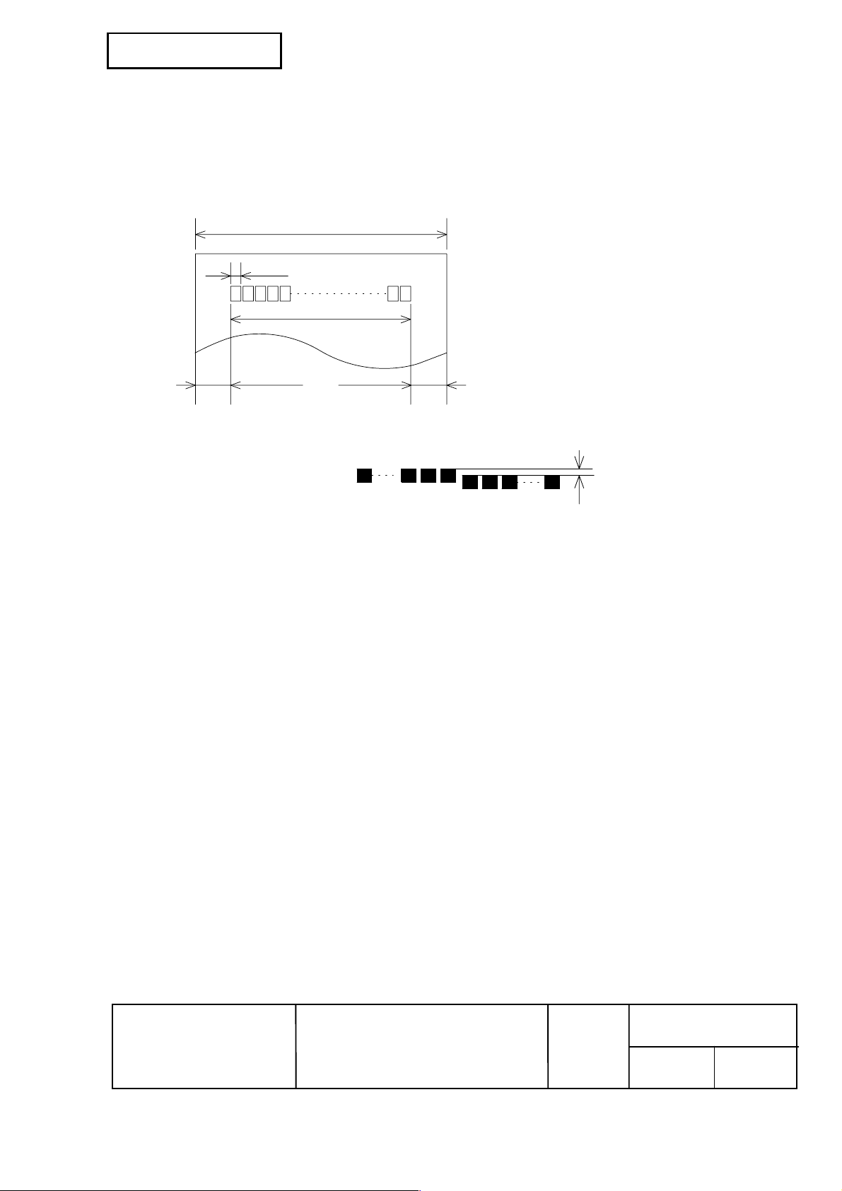
1.6 Printable Area
1) Paper roll
The printable area of a paper with width of 79.5 ± 0.5 m m {3.13 ± 0.02"} is 72.2 ± 0.2 m m {2.84 ±
0.008"} (512 dots) and the space on the right and left sides are approximately
3.7 ±2 mm {0.15 ± 0.079"}.
a
b
c
de
Figure 1.6.1 Paper Roll Printable Area
a = 79.5 ± 0.5 mm {3.13 ± 0.02"}
b = 0.141 ± 0.05 mm {0.056 ± .002"}
c = 72.2 ± 0.2 mm {2.84 ± .008"}
d = 3.7 ± 0.2 mm {0.15 ± 0.079"}
e = 3.7 ± 0.2 mm {0.15 ± 0.079"}
[All the numeric values are typical.]
1 256
257 512
Approximately 0.07mm (0.0028")
Figure 1.6.2 Shifting of the Print Position
NOTE: The print position within the printable area of the thermal elements for dots 257 to 512 is
shifted approximately 0.07 mm {0.003"} in the paper feed direction from the position for dots 1
to 256. Be sure not to print a ladder bar code across both printable areas, as this can cause
variations in printing which are difficult to read. However, when the ladder bar code is printed
with level 2 of print density, the difference is only approximately 0.04 ∼ 0.05 mm
{0.0015∼0.0019"}.
EPSON
TITLE
TM-T88III series
Specification
(STANDARD)
SHEET
REVISION
B
NO.
SHEETNEXT
6 5
Page 17
Confidential
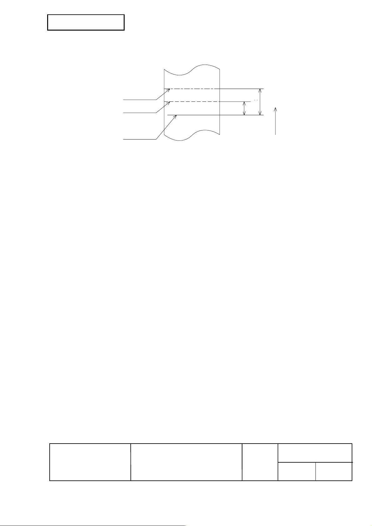
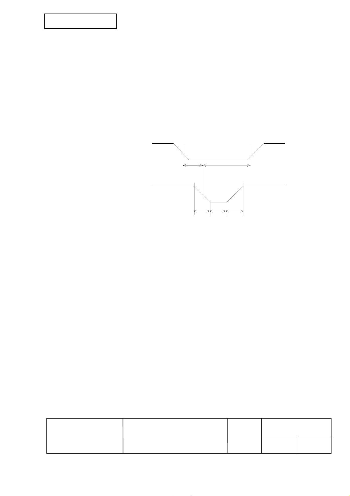
1.7 Printing and Cutting Posit i ons
NOTE: Numeric values used here are typical values; the values may vary slightly as a result of
1.8 Internal Buffer
1) Receive buffer selectable as 45 bytes or 4 KB using the DIP switch.
2) User-defined buffer (both for user-defined characters and user-defined bit images): 12 KB
3) Macro buffer: 2 KB
4) NV (Non-volatile) bit image buffer: 256 KB
5) NV user memory: 1 KB
Manual-cutter position
Auto-cutter blade position
Center of the print dotline
14.8
Approx. 15
Paper feed direction
[ Units: mm (All the numeric values are typical.) ]
26.3
Approx. 29
Figure 1.7.1 Printing and Cutting Positions
paper slack or variations in the paper. Take the notice into account when setting the cutting
position of the auto-cutter.
EPSON
TITLE
TM-T88III series
Specification
(STANDARD)
SHEET
REVISION
B
NO.
SHEETNEXT
7 6
Page 18

Confidential
1.9 Electrical Characteristics
1) Supply voltage: +24 VDC ± 7%
2) Current consumption (at 24V, room temperature):
High speed mode:
Mean: Approximately 1.8 A
(Character font A α-N, capital letters, 36-character rolling pattern,
42 columns printing)
Peak: Approximately 7.7 A
Low power consumption mode:
Mean: Approximately 1.2 A
(Character font A α-N, capital letters, 36-character rolling pattern,
42 columns printing)
Peak: Approximately 6.6 A
Standby:
Mean: Approximately 0.2 A
NOTE: Maximum 1 A for drawer kick-out driving.
1.10 EMI and Safety Standards Applied
EMC is measured using SEIKO EPSON’s AC adapter
1) Europe CE marking:
Directive: 89/336/EEC
EN55022 Class B
EN55024
IEC61000-4-2
IEC61000-4-3
IEC61000-4-4
IEC61000-4-5
IEC61000-4-6
IEC61000-4-11
Safety Standard: EN60950
2) North America EMI: FCC/ICES-003 Class A
Safety standards: UL1950/CSA C22.2 No.950
3) Japan EMC: VCCI Class A
4) Oceania EMC: AS/NZS 3548
5) Taiwan EMI: Class B
Conditions of Acceptability
1) This component has been judged on the basis of the required spacing in the Standard for
Information Technology equipment, Including Electrical Business Equipment, UL 1950 and CSA
C22.2 No. 950, Sub-clause 2.9, which would cover the component itself if submitted for Listing.
2) This unit is intended to be supplied by a SELV circuit only.
3) The terminals and connectors have not been evaluated for field wiring.
EPSON
TITLE
TM-T88III series
Specification
(STANDARD)
SHEET
REVISION
B
NO.
NEXT
8 7
SHEET
Page 19
Confidential
1.11 Reliability
1) Life:
Mechanism: 15,000,000 lines
Thermal head: 100 million pulses, 100 km
Auto cutter: 1,500,000 cuts
(End of life is defined to have reached the end of its life when it reaches
the beginning of the Wearout Period.)
2) MTBF: 360,000 hours
(Failure is defined as Random Failure occurring at the time of the
Random Failure Period.)
3) MCBF: 52,000,000 lines
(This is an average failure interval based on failures r elating to wearout
and random failures up to the life of 15 million lines.)
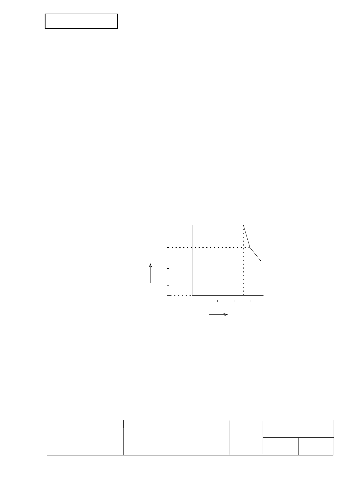
1.12 Environmental Condit i ons
1) Temperature: Operating: 5 to 45°C {41 to 113°F}
Storage: -10 to 50°C {14 to 122°F} (except for paper)
2) Humidity: Operating: 10 to 90% RH
Storage: 10 to 90% RH (except for paper)
[% RH]
34 ˚C, 90 %
Ambient
temperature
40 ˚C, 65 %
45 ˚C, 50 %
[˚C]
Relative humidity
90
80
60
40
20
10
0
Operating environment
range
0 10 20 30 40 50
Figure 1.12.1 Operating Temperature and Humidity Range
NOTE: If the printer is not used for a long time with paper installed, some part of the printing may be
light due to the deformation of the paper. If the printer is not used for a long time with paper
installed, be sure to feed paper approximately 30 mm {1.18"} before printing.
EPSON
TITLE
TM-T88III series
Specification
(STANDARD)
SHEET
REVISION
B
NO.
SHEETNEXT
9 8
Page 20

Confidential
3) Vibration resistance: When Packed: Frequency: 5 to 55 Hz
Acceleration: Approximately 19.6 m/s
Sweep: 10 minutes (half cycle)
Duration: 1 hour
Directions: x, y, and z
No external or internal damage should be f ound after the vibration test,
and the unit should operate normally.
4) Impact resistance: When Packed: Package: EPSON standard package
Height: 60 cm {23.6"}
Directions: 1 corner, 3 edges, and 6 surfaces
No external or internal damage should be found after the
drop test, and the unit should operate normally.
When unpacked: Height: 5 cm {1.97"}
Directions: Lift one edge and release it
(for all 4 edges).
W hen the printer is not printing, no external or inter nal damage should
be found after the drop test.
5) Acoustic noise(Operating): When using autocutter:
Approximately 55 dB (Bystander position)
When not using autocutter:
Approximately 45 dB (Bystander position)
2
{2 G}
1.13 Installation
The TM-T88III series printer must be installed horizontally.
(Vibration during paper cutting and using a drawer should be c onsidered. Take m easures to pr event
the printer from moving. Affixing tapes are provided as an option.)
An optional hanging bracket can attach the printer to a wall. (F ollowing the procedures describes in
the installation manual, install the wall mount and change the location of the paper r oll near- end s ens or,
then install the paper roll stopper and other parts.)
EPSON
TITLE
TM-T88III series
Specification
(STANDARD)
SHEET
REVISION
B
NO.
SHEETNEXT
10 9
Page 21

Confidential
2. CONFIGURATION
2.1 Interface
2.1.1 RS-232 serial interface
2.1.1.1 Specifications
Data transmission: Serial
Synchronization: Asynchronous
Handshaking: DTR/DSR or XON/XOFF control
Signal levels: MARK = -3 to -15 V: Logic "1"/ OFF
SPACE = +3 to +15 V: Logic "0"/ ON
Baud rate: 4800, 9600, 19200, 38400 bps
[bps: bits per second]
Data word length: 7 or 8 bits
Parity Settings: None, even, odd
Stop bits: 1 or more
Connector (printer side): Female DSUB-25 pin connector
NOTES: • The data word length, baud rate, and parity depend on the DIP switch settings. (Refer to
Section 3.3.3.)
• The stop bit for the printer side is fixed to 1.
2.1.1.2 Switching between online and offline
The printer does not have an online/offline switch.
The printer goes offline:
1) Between when the power is turned on (including reset using the interface) and when the printer is
ready to receive data.
2) During the self-test.
3) When the cover is open.
4) During paper feeding using the paper feed button.
5) When the printer stops printing due to a paper-end (in cases when an empty paper supply is
detected by either paper roll end detector or the paper roll near-end detector with a printing halt
feature by ESC c 4).
6) During macro executing standby status.
7) When a temporary abnormality occurs in the power supply voltage.
8) When an error has occurred.
EPSON
TITLE
TM-T88III series
Specification
(STANDARD)
SHEET
REVISION
B
NO.
SHEETNEXT
11 10
Page 22
Confidential
2.1.1.3 Interface connector terminal assignments and signal functions
Interface connector terminal assignments and signal functions are described in Table 2.1.1.
Table 2.1.1 TM-T88III Printer Status and Signals
Pin
number
20 DTR Output 1) When DTR/DSR control is selected, this signal indicates whether the
Signal
name
Signal
direction
Function
1 FG — Frame ground
2 TXD Output Transmit data
3 RXD Input Receive data
4 RTS Output Same as DTR signal
6 DSR Input This signal indicates whether the host computer can receive data.
SPACE indicates that the host computer can receive data, and MARK
indicates that the host computer cannot receive data.
When DTR/DSR control is selected, the printer transmits data after
confirming this signal (except when transmitting data by DLE EOT, and
GS a).
When XON/XOFF control is selected, the printer does not check this
signal.
Changing the DIP switch setting enables this signal to be used as a
reset signal for the printer (refer to Section 3.3.3).
The printer is reset when the signal remains MARK for
1 ms or more. (refer to Section 2.1.1.7)
7 SG — Signal ground
printer is busy. SPACE indicates that the printer is ready to receive
data, and MARK indicates that the printer is busy. The busy
condition can be changed by using DIP SW 2-1 as follows (refer to
Section 3.3.3):
Printer status ON OFF
1. During the period from when the power is
turned on (including resetting using the
interface) to when the printer is ready to receive
data.
2. During the self-test. BUSY BUSY
3. When the cover is open. — BUSY
4. During paper feeding using the paper feed
button.
Offline
5. When the printer stops printing due to a
paper-end.
6. During macro executing standby status. — BUSY
7. When a temporary abnormality occurs in the
power supply voltage.
8. When an error has occurred. — BUSY
9. When the receive buffer becomes full.(*1) BUSY BUSY
DIP SW 2-1 s tatus
BUSY BUSY
— BUSY
— BUSY
— BUSY
EPSON
TITLE
TM-T88III series
Specification
(STANDARD)
SHEET
REVISION
B
NO.
SHEETNEXT
12 11
Page 23
Confidential
Table 2.1.1 TM-T88III Printer Status and Signals (Continued)
Pin
number
25 INIT Input Changing the DIP switch setting enables this signal to be used as a
*1 • Definition of “receive buffer full”
• The printer ignores the data received when the remaining space in the receive buffer
Signal
name
2) When XON/XOFF control is selected:
• When the receive buffer capacity is specified to 4 KB (DIP SW1-2 is Off):
• If the DIP SW 2-5 is of f, when the remaining s pace in the receive buff er drops to 128 bytes,
the printer status becomes “buffer full” and it remains “buffer full” until the space in the
receive buffer increases to 256 bytes.
• If the DIP SW 2-5 is on, when the rem aining space in the receive buf fer dr ops to 128 bytes,
the printer status becomes “buffer full” and it remains “buffer full” until the space in the
receive buffer increases to 138 bytes.
• When the receive buffer capacity is specified to 45 bytes (DIP SW1-2 is On):
• Regardless of the DIP SW2-5 setting, when the rem aining space in the receive buff er drops
to 16 bytes, the printer status becomes “buffer f ull” and it re mains “buffer full” until the s pace
in the receive buffer increases to 26 bytes.
is 0 bytes.
Signal
direction
Function
The signal indicates whether the printer is correctly connected and
is ready to receive data. SPACE indicates that the printer is ready
to receive data. The signal is always SPACE except in the
following cases:
• During the period from when the power is turned on to when the
printer is ready to receive data
• During the self-test
reset signal for the printer.
The printer is reset when the signal remains SPACE for 1 ms or more.
2.1.1.4 XON/XOFF transmit timing
When X ON/X O FF contr ol is selec ted, the pr inter tr ans mits XON or XOFF s ignals as f ollows. Transmit
timing differs depending on the DIP SW2-1 setting.
Table 2.1.2 XON/XOFF Transmit Timing
XON
transmission
XOFF
Transmission
NOTES: • The XON code is <11>H and the XOFF code is <13>H.
• In case
• In case
EPSON
Printer status
① When the printer goes online after turning on the power (or
reset using interface)
② When the receive buffer is released from the buffer full state
③ When the printer switches from offline to online
④ When the printer recovers from an error using the
DLE ENQ 1 or DLE ENQ 2 commands
⑤ When the receive buffer becomes full
⑥ When the printer switches from online to offline
③, XON is not transmitted when the receive buffer is full.
⑥, XOFF is not transmitted when the receive buffer is full.
TITLE
TM-T88III series
Specification
(STANDARD)
SHEET
REVISION
B
DIP SW 2-1 status
ON OFF
Transmit Transmit
Transmit Transmit
— Transmit
— Transmit
Transmit Transmit
— Transmit
NO.
13 12
SHEETNEXT
Page 24
Confidential
2.1.1.5 Serial interface connection example
Host side Printer side
(DTE ex.8251)
TXD ....................................RXD
DSR....................................DTR
CTS ....................................RTS
RXD....................................TXD
DTR....................................DSR
FG.......................................FG
SG ......................................SG
NOTES: • Set the handshaking so that the transmit data can be received.
• Transmit data to the printer after turning on the power and initializing the printer.
2.1.1.6 Notes on setting DIP switch 2-1 to ON
1) The printer mechanis m stops but does not becom e bus y when: an error has oc curred, the c over is
open, printing stops due to a paper-end, or paper is fed using the paper feed button.
2) W hen setting DIP switch 2-1 to ON to enable handshaking with the printer, be sure to chec k the
printer status using the GS a command and the ASB function. In this setting, the default value of
n for GS a is 2. The printer automatically transmits the printer status, depending on online/offline
changes.
3) When using DLE EOT, DLE ENQ, and DLE DC4 be sure that the receive buff er does not becom e
full.
• When using a host that cannot transmit data when the printer is busy:
If an error has occurred, DLE EOT, DLE ENQ , and DLE DC4 c annot be used when the printer
is busy due to a receive buffer-full state.
• When using a host that can transmit data when the printer is busy:
W hen the receive buffer becom es full while transmitting bit- image data, DLE EOT, DLE ENQ
or DLE DC4 used while sending the bit-image data is processed as bit-image data. The data
transmitted when the receive buffer is full may be lost.
Example: Check the printer status using GS r after transmitting each line of data and use
the 4 KB receive buffer. Transmit one line of data so that the receive buffer
does not become full.
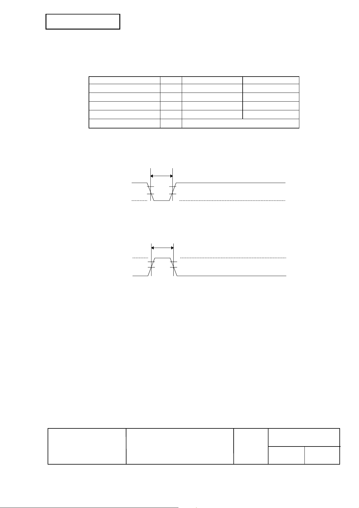
2.1.1.7 Notes on Resetting the Printer Using the Interface
The printer can be reset using interface pins 6 and 25 by changing the DIP switch setting (refer to
Section 3.3.3, DIP switch 2).
Table 2.1.3 Reset Switching
Signal Line DIP Switch Reset Condition
Pin 6 (DSR) DSW 2-7: ON MARK level input
Pin 25 (INIT) DSW 2-8: ON SPACE or TTL-HIGH level input
EPSON
TITLE
TM-T88III series
Specification
(STANDARD)
SHEET
REVISION
B
NO.
14 13
SHEETNEXT
Page 25
Confidential
To reset the printer, the following requirements must be satisfied.
• DC characteristics:
Pin 6 (DSR) Pin 25 (INIT)
Reset active voltage VA -15 to -3 V +2 to +15 V
Reset negative voltage VN +3 to +15 V -15 to + 0.8 V
Reset active current IA -5.3 mA (maximum) 1 mA (maximum)
Reset negative current IN -5.0 mA (maximum) -2 mA (maximum)
Input impedance RIN
• AC characteristics:
Minimum reset pulse width: T
• When using pin 6 (DSR) (DIP switch 2-7 is ON):
SPACE
Table 2.1.4 Reset DC Characteristics
3 kΩ (minimum)
RS 1 ms (minimum)
TRS
TRS
H
L
MARK
Figure 2.1.1 Minimum Reset Pulse Width (pin 6)
• When using pin 25 (INIT) (DIP switch 2-8 is ON):
SPACE (H)
MARK (L)
TRS
H
L
TRS
Figure 2.1.2 Minimum Reset Pulse Width (pin 25)
NOTES: • When a signal that does not satisfy the requirements above is input, printer operation is
not guaranteed. When a signal is input to pin 25 (INIT) at the TTL level, the
requirements above must also be satisfied. Although a signal is input to pin 6 (DSR) at
the TTL level, according to the DC characteristics described above, the operation is not
guaranteed and pin 6 cannot be controlled.
• When pin 6 (DSR) and pin 25 (INIT) are open, the printer is operating.
EPSON
TITLE
TM-T88III series
Specification
(STANDARD)
SHEET
REVISION
B
NO.
SHEETNEXT
15 14
Page 26

Confidential
2.1.2 IEEE 1284 Bidirectional Parallel Interface
Copyright © 1994 by the Institute of Electrical and Electronic Engineers, Inc.
2.1.2.1 Compatibility Mode
(Data Transmission from Host to Printer: Centronics compatible)
1) Outline
Compatibility mode supports the compatibility with Centronics parallel interface.
2) Specifications
Data transmission: 8-bit Parallel
Synchronization: Externally supplied nStrobe signals
Handshaking: nAck and Busy signals
Signal levels: TTL compatible
Connector: ADS-B36BLFDR176 (Honda) or equivalent (IEEE 1284 Type B)
3) Switching between online and offline
The printer is not equipped with any online/offline switch. The printer is placed into of fline status
in either of the followings:
1) W hen the power is turned on or until the printer becom es ready for data transmis sion after it
is initialized by the reset signal (nInit) from the interface.
2) During the self-test.
3) When the cover is open.
4) During paper feeding using the paper feed button.
5) When the printer stops printing due to a paper-end (in cases when empty paper supply is
detected by either the paper roll end detector or the paper roll near-end detector with a
printing halt due to paper shortage enabled by ESC c 4).
6) During macro executing standby status.
7) When a temporary abnormality occurs in the power supply voltage.
8) When an error has occurred.
2.1.2.2 Reverse Mode (Data Transmission from Printer to Host)
The STATUS data transmission from the printer to the host is proceeded in the Nibble or Byte mode.
• Description
This mode allows data transmission from the asynchronous printer under the control of the host.
Data transmissions in the Nibble Mode are made via the existing control lines in units of four bits
(Nibble). In the Byte Mode, data transmissions are proceeded by making the eight-bits data
lines bidirectional.
The both modes fail to be pr oceeded concurrently with the Compatibility Mode, thereby causing
half duplex transmission.
EPSON
TITLE
TM-T88III series
Specification
(STANDARD)
SHEET
REVISION
B
NO.
SHEETNEXT
16 15
Page 27
Confidential
2.1.2.3 Interface Pin Assignments for Each Mode
Pin Source Compatibility Mode Nibble Mode Byte Mode
1 Host nStrobe HostClk HostClk
2 Host/Ptr Data0(LSB) Data0(LSB) Data0(LSB)
3 Host/Ptr Data1 Data1 Data1
4 Host/Ptr Data2 Data2 Data2
5 Host/Ptr Data3 Data3 Data3
6 Host/Ptr Data4 Data4 Data4
7 Host/Ptr Data5 Data5 Data5
8 Host/Ptr Data6 Data6 Data6
9 Host/Ptr Data7(MSB) Data7(MSB) Data7(MSB)
10 Printer nAck PtrClk PtrClk
11 Printer Busy PtrBusy/Data3, 7 PtrBusy
12 Printer PError AckDataReq/Data2, 6 AckDataReq
13 Printer Select Xflag/Data1, 5 Xflag
14 Host nAutoFd HostBusy HostBusy
15 NC ND ND
16 GND GND GND
17 FG FG FG
18 Printer Logic-H Logic-H Logic-H
19 GND GND GND
20 GND GND GND
21 GND GND GND
22 GND GND GND
23 GND GND GND
24 GND GND GND
25 GND GND GND
26 GND GND GND
27 GND GND GND
28 GND GND GND
29 GND GND GND
30 GND GND GND
31 Host nInit nInit nInit
32 Printer nFault nDataAvail/Data0, 4 nDataAvail
33 GND ND ND
34 Printer DK_STATUS ND ND
35 Printer +5V ND ND
36 Host nSelectIn 1284-Active 1284-Active
*NC: Not Connected
ND: Not Defined
EPSON
TITLE
TM-T88III series
Specification
(STANDARD)
SHEET
REVISION
B
NO.
SHEETNEXT
17 16
Page 28
Confidential
NOTES: 1. A prefix “n” to signal names refers to “L” active signals. To the host provided with none of
the signal lines listed above, both-way communication fails.
2. For interfacing, signal lines shall use twisted pair cables with the return sides connected
to signal ground level.
3. Interfacing conditions shall be all based on the TTL level to meet the characteristics
described below. In addition, both rise time and fall time of each signal shall be
0.5 µs or less.
4. Data transmission shall not ignore the signal nAck or Busy. An attempt to transmit data
with either signal, nAck or Busy, ignored can cause lost data. (Data transmissions to
the printer shall be made after verifying the nAck signal or while the Busy signal is at the
“L” level.)
5. Interface cables shall be as minimum required short in length as possible.
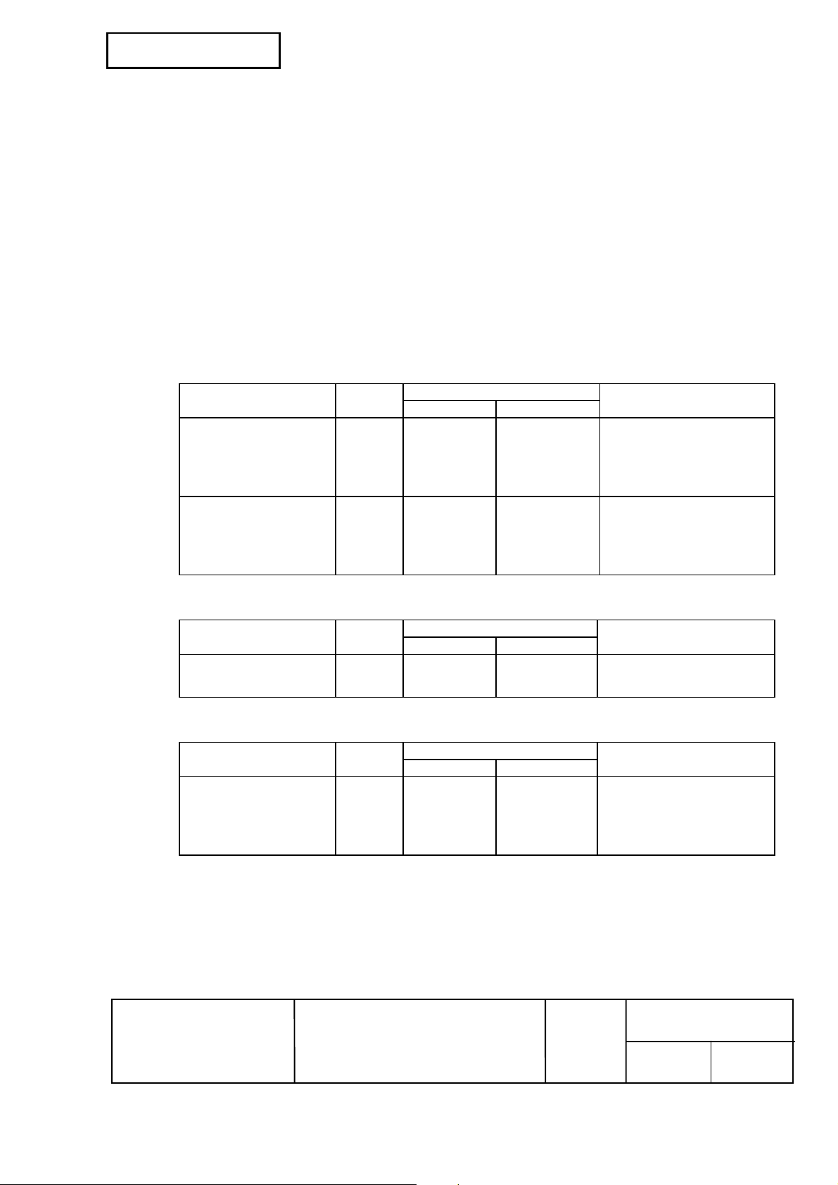
2.1.2.4 Electrical Characteristics
DC Characteristics (Except Logic-H, +5 V signals)
Characteristics Symbol
Output HIGH voltage VOH *2.4 V 5.5 V *IOH=0.32 mA
Output LOW voltage VOL -0.5 V *0.4 V *IOL=-12 mA
Output HIGH current IOH 0.32 mA - VOH=2.4 V
Output LOW current IOL -12 mA - VOL=0.4 V
Input HIGH voltage VIH 2.0 V -
Input LOW voltage VIL - 0.8 V
Input HIGH current IIH - -0.32 mA VIH=2.0 V
Input LOW current IIL - 12 mA VIL=0.8 V
Specifications
Min Max
Conditions
Characteristics Symbol
Output HIGH voltage
Output LOW voltage
Characteristics Symbol
Output HIGH voltage VOH *2.4 V 5.5 V *IOH=0.32 mA
Output LOW voltage VOL - - ** While the power is OFF
Output HIGH current IOH - 0.32 mA VOH=2.4 V
Output LOW current IOL - ** - While the power is OFF
** No guarantee is offered to VOL and IOL while the power is OFF.
EPSON
Logic-H Signal Sender Characteristics
Specifications
Min Max
VOH
V
OL
+5 V Signal Sender Characteristics
TITLE
3.0 V
-
Specifications
Min Max
TM-T88III series
Specification
(STANDARD)
5.5 V
2.0 V
SHEET
REVISION
Conditions
While the power is OFF
Conditions
NO.
B
18 17
SHEETNEXT
Page 29
Confidential
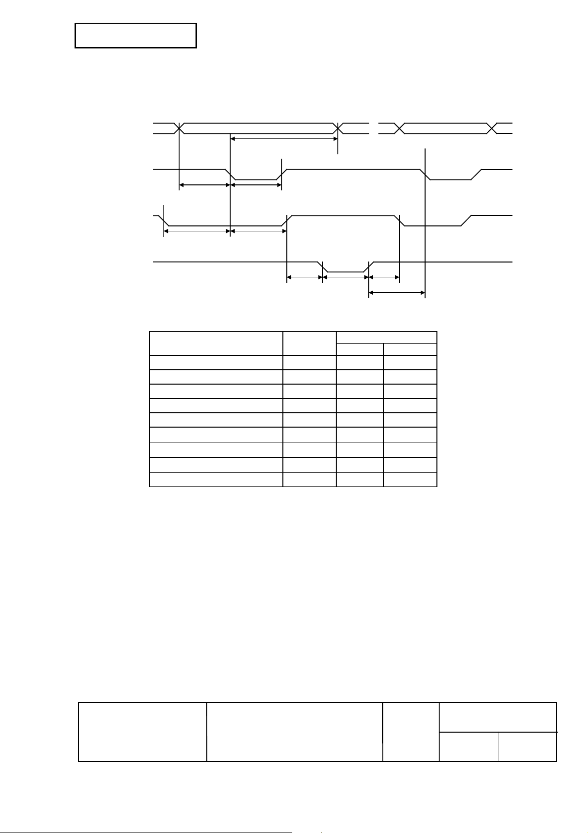
2.1.2.5 Data Receiving Timing (Compatibility Mode)
DATA Data n Data n+1
nStrobe
Busy Peripheral Busy
nAck
Characteristics Symbol
Data Hold Time (host) tHold 750 --
Data Setup Time tSetup 750 -STROBE Pulse Width tSTB 750 -READY Cycle Idle Time tReady 0 -BUSY Output Delay Time tBUSY 0 500
Data Processing Time tReply 0
ACKNLG Pulse Width tACK 500
BUSY Release Time tnBUSY 0
ACK Cycle Idle Time tNext 0 --
*The printer latches data at a nStrobe ↓ timing
tSTB tSetup
tBUSYtReady
tHold
tnBUSYtACK tReply
tNext
Specifications
Min[ns] Max[ns]
∞
10µs
∞
EPSON
TITLE
TM-T88III series
Specification
(STANDARD)
SHEET
REVISION
B
NO.
SHEETNEXT
19 18
Page 30
Confidential
2.1.2.6 Notes on resetting the printer through the interface
To enable the printer reset in compatibility mode, the following signal timing shall be satisfied.
However, the printer reset is ignored when the signal nSelectln (#36 pin, 1284-Ac tie high) is active in
reverse mode.
• DC characteristic:
TTL level
• AC characteristics:
Minimum reset pulse width: TRS 50 µs (min.)
Trailing edge period: tf 500 ns (max.)
Leading edge period: tr 500 ns (max.)
nSelectIn
(1284-Active)
min.0
nInit
min.1ms
tf
TRS
tr
EPSON
TITLE
TM-T88III series
Specification
(STANDARD)
SHEET
REVISION
B
NO.
SHEETNEXT
20 19
Page 31

Confidential
2.1.2.7 Reception of status from the printer through the bidirectional parallel interface
In the bidirectional parallel interface spec ifications, the printer st atus transmiss ion is available by using
the both-way communication facility in the Nibble/Byte Modes in accordance with the IEEE 1284.
In this case, different from in the RS-232 s erial interface spec ifications, the real- time interruptions from
the printer to the host are disabled and thus precautions must be taken to the followings.
1) Allowable capacity of the printer internal buffer is 99 bytes (except ASB status). The status
signals exceeding this capacity will be discarded. To prevent possible loss of status, the host
shall be ready for data acception (Reverse Mode).
2) When ASB is used, the host is preferably in the wait state for data acception (Rever se Idle Mode).
When this state is not available, the host shall enter the Reverse Mode to always monitor the
presence of data.
3) When ASB is used, preference shall be given to the ASB status f or transmission over the other
status signals. Any accumulated ASB status signals left for transmission from the last to the
newest ASB status transmission shall be transmitted together at a time as one ASB status
showing the presence of change, followed by the latest ASB status.
Example: In the normal (wait) state, the ASB status is configured as follows.
First Status Second Status Third Status Fourth Status
0001 1000 0000 0000 0000 0000 0000 0000
When a sequence of operations ar e proceeded, the near end is detected and
the printer cover is opened, then the printer cover is closed, the following
pieces of data are accumulated.
First Status Second Status Third Status Fourth Status
0001 1000 0000 0000 0000 0011 0000 0000 Near end detection
①
0011 1000 0000 0000 0000 0011 0000 0000 The printer cover is opended.
②
0001 1000 0000 0000 0000 0011 0000 0000 The printer cover is closed.
③
When the ASB status is received following this, a total of eight (8) bytes of
ASB will be transmitted as follows.
Accumulated ASB (
Accumulated ASB (①+②+③)
+
The latest ASB (③)
Fourth Status
First Status Second Status Third Status Fourth Status
0011 1000 0000 0000 0000 0011 0000 0000
First Status Second Status Third Status Fourth Status
0001 1000 0000 0000 0000 0011 0000 0000
①+②+③)
2.1.2.8 Notes on setting DIP switch 2-1 to ON
Refer to Section 2.1.1.6.
EPSON
TITLE
TM-T88III series
Specification
(STANDARD)
SHEET
REVISION
B
NO.
SHEETNEXT
21 20
Page 32

Confidential
2.1.3 RS-485 Serial Interface
(An RS-485 serial is a factory option.)
2.1.3.1 Specifications (RS-485 compatible)
Data transmission: Serial
Synchronization: Asynchronous
Handshaking: Depend on the DIP switch settings
(DTR/DSR or XON/XOFF control)
Signal levels: 2.0 to 5.0 V: Logic 1
0.0 to 0.8 V: Logic 0
Baud rates: 4800, 9600, 19200, 38400 bps
Data word lengths: 7 or 8 bits
Parity settings: None, even, odd
Stop bits: 1 or more
Connector (printer side): Female D-SUB25 pin connector
NOTES: • The handshaking data word length, baud rate, and parity depend on the DIP switch
(Refer to Section 3.3.3)
• Data transmitted from the printer has 1 stop bit (fixed).
DR1 > DR2 CS1 > CS2 indicates that:
Channel 1 is high.
Channel 2 is low.
DR1 < DR2 CS1 < CS2 indicates that:
Channel 2 is high.
Channel 1 is low.
CS1 CS2 Function
H L Communication is available
L H Communication is not available
NOTE: • If the electric potential of CS1 is higher than that of CS2, the printer is ready for
communication (the host is ready to receive data). If the electric potential of CS1 is
lower than that of CS2, the printer is not ready for communication (the host is not ready
to receive data).
DR1 DR2 Function
H L Communication is available
L H Communication is not available
NOTE: • If the electric potential of DR1 is higher than that of DR2, the printer is ready for
communication (the host is ready to receive data). If the electric potential of DR1 is
lower than that of DR2, the printer is not ready for communication (the host is not ready
to receive data).
EPSON
TITLE
TM-T88III series
Specification
(STANDARD)
SHEET
REVISION
B
NO.
SHEETNEXT
22 21
Page 33

Confidential
2.1.3.2 Switching between online and offline
The printer does not have an online/offline switch.
The printer goes offline:
1) Between when the power is turned on (including reset using the interface) and when the printer is
ready to receive data.
2) During the self-test.
3) When the cover is open.
4) During paper feeding using the paper feed button.
5) When the printer stops printing due to paper-end (in cases when an empty paper supply is
detected by either paper roll and detector or the paper roll near-end detector with a printing halt
feature set enabled due to paper shortage by ESC c 4).
6) During macro executing standby status.
7) When a temporary abnormality occurs in the power supply voltage.
8) When an error has occurred.
9) When the receive buffer becomes full. (*1)
*1 • Definition of “receive buffer full”
• When the receive buffer capacity is specified to 4 KB (DIP SW1-2 is Off):
• If the DIP SW 2-5 is of f, when the remaining s pace in the receive buff er drops to 128 bytes,
the printer status becomes “buffer full” and it remains “buffer full” until the space in the
receive buffer increases to 256 bytes.
• If the DIP SW 2-5 is on, when the rem aining space in the receive buf fer dr ops to 128 bytes,
the printer status becomes “buffer full” and it remains “buffer full” until the space in the
receive buffer increases to 138 bytes.
• When the receive buffer capacity is specified to 45 bytes (DIP SW1-2 is On):
• Regardless of the DIP SW2-5 setting, when the rem aining space in the receive buff er drops
to 16 bytes, the printer status becomes “buffer f ull” and it re mains “buffer full” until the s pace
in the receive buffer increases to 26 bytes.
• The printer ignores the data received when the remaining space in the receive buffer
is 0 bytes.
* For notes on setting DIP switch 2-1 to ON, refer to Section 2.1.1.6.
EPSON
TITLE
TM-T88III series
Specification
(STANDARD)
SHEET
REVISION
B
NO.
SHEETNEXT
23 22
Page 34

Confidential
2.1.3.3 Interface pin assignments
Table 2.1.5 TM-T88III Printer Status and Signals
Pin
Number
1 FG -- Frame ground
2
3
4
5
7 SG -- Signal ground
8
9
Signal
name
SD1
SD2
RD1
RD2
DR1
DR2
Signal
direction
Output Transmit data
Input Receive data
Output When DTR/DRS is selected, this signal indicates whether the host
Function
computer is BUSY or READY.
1) DR1>DR2 indicates that the printer is READY and DR1<DR2
indicates that the printer is BUSY. The BUSY condition can be
changed depending on the offline conditions set by the DIP switches
(refer to Section 3.3.3).
When the DTR/DSR control is selected, the printer becomes the
BUSY state (DR1<DR2) under the following conditions.
Printer status
1. During the period from when the power is
turned on (including resetting using the
interface) to when the printer is ready to
receive data.
2. During the self-test. BUSY BUSY
3. When the cover is open. — BUSY
4. During paper feeding using the paper
feed button.
Offline
5. When the printer stops printing due to a
paper-end. (only when the paper roll is
not present)
6. During macro executing standby status. — BUSY
7. When a temporary abnormality occurs in
the power supply voltage.
8. When an error has occurred. — BUSY
9. When the receive buffer becomes full.(*1) BUSY BUSY
2) When XON/XOFF control is selected:
The signal indicates whether the printer is correctly connected and is
ready to receive data. SPACE indicates that the printer is ready to
receive data. The signal is always DR1>DR2 (READY) indicates
that the printer is ready to receive data. The signal is always
DR1>DR2 except in the following cases:
• During the period from when the power is turned on to when the
printer is ready to receive data
• During the self-test
DIP SW 2-1 status
ON OFF
BUSY BUSY
— BUSY
— BUSY
— BUSY
EPSON
TITLE
TM-T88III series
Specification
(STANDARD)
SHEET
REVISION
B
NO.
SHEETNEXT
24 23
Page 35

Confidential
Table 2.1.5 TM-T88III Printer Status and Signals (Continued)
Pin
Number
10
11
*1 • Definition of “receive buffer full”
• The printer ignores the data received when the remaining space in the receive buffer
Signal
name
CS1
CS2
• When the receive buffer capacity is specified to 4 KB (DIP SW1-2 is Off):
• If the DIP SW 2-5 is of f, when the remaining s pace in the receive buff er drops to 128 bytes,
the printer status becomes “buffer full” and it remains “buffer full” until the space in the
receive buffer increases to 256 bytes.
• If the DIP SW 2-5 is on, when the rem aining space in the receive buf fer dr ops to 128 bytes,
the printer status becomes “buffer full” and it remains “buffer full” until the space in the
receive buffer increases to 138 bytes.
• When the receive buffer capacity is specified to 45 bytes (DIP SW1-2 is On):
• Regardless of the DIP SW2-5 setting, when the rem aining space in the receive buff er drops
to 16 bytes, the printer status becomes “buffer f ull” and it re mains “buffer full” until the s pace
in the receive buffer increases to 26 bytes.
is 0 bytes.
Signal
direction
Input This signal indicates whether the host computer is BUSY or READY.
Function
CS1>CS2 indicates that the printer is READY and CS1<CS2
indicates that the printer is BUSY.
1) When DTR>DSR is selected:
The signal is checked and data is transmitted only when the host is
ready to receive data (READY) (except for transmitted by DLE EOT
or GS a).
2) When XON/XOFF control is selected:
Transmits data regardless of the status of this signal.
EPSON
TITLE
TM-T88III series
Specification
(STANDARD)
SHEET
REVISION
B
NO.
SHEETNEXT
25 24
Page 36

Confidential
2.1.3.4 XON/XOFF transmit timing
Refer to Section 2.1.1.4.
For the DIP switch settings of the offline status, refer to Section 2.1.1.6.
2.1.3.5 Data format when using RS-485
Transmission data (8 bits, none parity)
H
L
“H” indicates
<Printer transmission data> SD1<SD2
<Printer reception data> RD1<RD2
“L” indicates:
<Printer transmission data> SD1>SD2
<Printer reception data> RD1>RD2
The transmission data is H = 1, L = 0
NOTE: This format is used when the UART for RS-232 is connected to the RS-485 driver.
START
123 45678
RS-485 Communication data format
Printer Reception Data Level
DR1 DR2 Read data
H L Receiving data line is low level
L H Receiving data line is high level
STOP
Printer Transmission Data Level
SD1 SD2 Send data
H L Sending data line is low level
L H Sending data line is high level
2.1.4 Other Interfaces
Various interface boards (EPSON UB series) can be used.
EPSON
TITLE
TM-T88III series
Specification
(STANDARD)
SHEET
REVISION
B
NO.
SHEETNEXT
26 25
Page 37

Confidential
2.2 Connectors
2.2.1 Interface Connectors
Refer to Section 2.1, Interface.
2.2.2 Power Supply Connector
This connector is used to connect the printer to an external power source.
1) Pin assignments: Refer to Table 2.2.1.
Table 2.2.1 Power Supply Connector Pin Assignments
Pin Number Signal Name
1 +24 V
2 GND
3 NC
SHELL F.G.
SHELL
Figure 2.2.1 Power Supply Connector
NOTE: Be sure to ground the metal of the interface using the hole for the frame ground.
2) Connector model: Printer side: Hosiden TCS7960-532010 or equivalent
User side: Hosiden TCP8927-631100 or equivalent
Hosiden TCP8927-531100 or equivalent
EPSON
TITLE
TM-T88III series
Specification
(STANDARD)
SHEET
REVISION
B
NO.
SHEETNEXT
27 26
Page 38

Confidential
2.2.3 Drawer Kick-out Connector (Modular Connector)
The pulse specified by ESC p or DLE DC4 is output to this connector. The host can confirm the status
of the input signal by using the
1) Pin assignments: Refer to Table 2.2.2
Table 2.2.2 Drawer Kick-out Connector Pin Assignments
Pin Number Signal Name Direction
1 Frame GND —
2 Drawer kick-out drive signal 1 Output
3 Drawer open/close signal Input
4 +24 V —
5 Drawer kick-out drive signal 2 Output
6 Signal GND —
+24 V is output through pin 4 when the power is turned on. However, pin 4 must be used only
for the drawer.
DLE EOT, GS a, or GS r commands.
16
Figure 2.2.2 Drawer Kick-out Connector
2) Connector model: Printer side: MOLEX 52065-6615 or equivalent
User side: 6-position 6-contact (RJ12 telephone jack)
3) Drawer kick-out drive signal
Output signal: Output voltage: Approximately 24 V
Output current: 1 A or less
CAUTION: To avoid an overcurrent, the resistance of the drawer kick-out solenoid must be 24 Ω
or more.
Output waveform: Outputs the waveforms in Figure 2.2.3 to the points A and B in
Figure 2.2.4.
Figure 2.2.3 Drawer Kick-out Drive Signal Output Waveform
t1 (ON time) and t2 (OFF time) are specified by ESC p or DLE DC4.
t 1x 2 msec
t2 x 2 mst1 x 2 ms
t 1x 2 msec
EPSON
TITLE
TM-T88III series
Specification
(STANDARD)
SHEET
REVISION
B
NO.
SHEETNEXT
28 27
Page 39

Confidential
4) Drawer open/close signal
Input signal level (connector pin 3): "L" = 0 to 0.8 V
"H" = 2 to 5 V
A
F. G
Drawer kick-out connector
1
2
3
With shielded
Drawer kick-out solenoid
P-GND
B
P-GND
Printer side User side (Drawer kick-out side)
+24V
4
5
6
Drawer open/close switch
Figure 2.2.4 Drawer Circuitry
NOTES: 1. Use a shielded cable for the drawer connector cable.
2. Two driver transistors cannot be energized simultaneously.
3. The drawer drive duty must be as shown below.
ON time
(ON time + OFF time)
≤ 0.2
4. Be sure to use the printer power supply (connector pin 4) for the drawer power source.
5. The resistance of the drawer kick-out solenoid must not be less than the specified.
Otherwise, an overcurrent could damage the solenoid.
6. Do not connect telecommunication network to the drawer kick-out connector.
EPSON
TITLE
TM-T88III series
Specification
(STANDARD)
SHEET
REVISION
B
NO.
SHEETNEXT
29 28
Page 40

Confidential
3. FUNCTIONS
3.1 List of commands
Command Name
HT
LF
FF
CR
CAN
DLE EOT
DLE ENQ
DLE DC4
ESC FF
ESC SP
ESC !
ESC $
ESC %
ESC &
ESC ∗∗∗∗
ESC ESC 2
ESC 3
ESC =
ESC ?
ESC @
ESC D
ESC E
ESC G
ESC J
ESC L
ESC M
ESC R
ESC S
ESC T
ESC V
Horizontal tab
Print and line feed
Print and return to standard mode (in page mode)
Print and carriage return
Cancel print data in page mode
Real-time status transmission
Real-time request to printer
Generate pulse at real-time
Print data in page mode
Set right-side character spacing
Select print mode(s)
Set absolute print position
Select/cancel user-defined character set
Define user-defined characters
Select bit-image mode
Turn underline mode on/off
Select default line spacing
Set line spacing
Select peripheral device
Cancel user-defined characters
Initialize printer
Set horizontal tab positions
Turn emphasized mode on/off
Turn double-strike mode on/off
Print and feed paper
Select page mode
Select character font
Select an international character set
Select standard mode
Select print direction in page mode
Turn 90° clockwise rotation mode on/off
Command
classification
Executing Setting
{
{
{
{
{
{
{
{
{
{
{
{ { { {
{
{
{
Standard
mode
Ignored
Ignored
Ignored
{ { { {
{ { {
{ { {
{ { {
{ { {
{ { {
{ { { {
{ { {
{ { {
{ { {
{ { {
{ { {
({) Ignored
{ { {
Ignored
{
{ {
{ {
{ {
{ {
{ {
{ {
{ {
{ { {
{ {
{ { {
{ {
▲
Page
mode
{
{
{
{
{
▲
GS P
function
EPSON
TITLE
TM-T88III series
Specification
(STANDARD)
SHEET
REVISION
B
NO.
SHEETNEXT
30 29
Page 41

Confidential
Command
ESC W
ESC \
ESC a
ESC c 3
ESC c 4
ESC c 5
ESC d
ESC p
ESC t
ESC {
FS g 1
FS g 2
FS p
FS q
GS !
GS $
GS ∗∗∗∗
GS ( A
GS /
GS :
GS B
GS H
GS I
GS L
GS P
GS V
GS W
GS \
GS ^
GS a
GS b
GS f
Name
Set printing area in page mode
Set relative print position
Select justification
Select paper sensor(s) to output paper-end signals
Select paper sensor(s) to stop printing
Enable/disable panel buttons
Print and feed n lines
General pulse
Select character code table
Turn upside-down printing mode on/off
Write to NV user memory
Read from NV user memory
Print NV bit image
Define NV bit image
Select character size
Set absolute vertical print position in page mode
Define downloaded bit image
Execute test print
Print downloaded bit image
Start/end macro definition
Turn white/black reverse printing mode on/off
Select printing position of HRI characters
Transmit printer ID
Set left margin
Set horizontal and vertical motion units
Select cut mode and cut paper
Set printing area width
Set relative vertical print position in page mode
Execute macro
Enable/disable Automatic Status Back (ASB)
Turn smoothing mode on/off
Select font for HRI characters
Command
classification
Executing Setting
{
{
{
{
{
{
{
{
{ { { {
{
{
Ignored
{
{ { { {
Standard
mode
{
{
{ { {
{ { {
{ { {
{ { {
{
{ {
{
{ { {
Ignored
{ { {
{ { {
{ { {
{
{ { {
({)
{
{ { {
{ { {
▲
{ { {
({)
{ {
{ {
({)
{ {
{
({)
{
●
{ {
({)
({)
{ {
Page
mode
{ {
▲
▲
Disabled
Disabled
Disabled
{ {
Disabled
{
▲
{ {
▲
{ {
GS P
function
{
{
EPSON
TITLE
TM-T88III series
Specification
(STANDARD)
SHEET
REVISION
B
NO.
SHEETNEXT
31 30
Page 42

Confidential
Command
GS h
GS k
GS r
GS v 0
GS w
Name
Set bar code height
Print bar code
Transmit status
Print raster bit image
Set bar code width
Kanji command list
(when the Japanese, Simplified Chinese, Traditional Chinese, or Korean model is used)
Command
Name
Command
classification
Executing Setting
{
{
{
Command
classification
Executing Setting
{ { {
{ { {
Standard
mode
●
{ {
●
Standard
mode
Page
mode
{
Disabled
Page
mode
GS P
function
GS P
function
FS !
FS &
FS –
FS .
FS 2
FS C
FS S
FS W
Set print mode(s) for Kanji characters
Select Kanji character mode
Turn underline mode on/off for Kanji characters
Cancel Kanji character mode
Define user-defined Kanji characters
Select Kanji character code system
Set Kanji character spacing
Turn quadruple-size mode on/off for Kanji
characters
Command classification
Executing: Printer executes the command, which does not then affect the following data.
Setting: Printer uses flags to make settings, and those settings affect the following data.
Standard mode
{: Enabled.
({): Enabled only when the command is set at the beginning of a line.
●: Enabled only when data is not present in the printer buffer.
Page mode
{: Enabled.
▲: Only value setting is possible.
Disabled: Parameters are processed as printable data.
Ignored: All command codes including parameters are ignored and nothing is executed.
{ { {
{ { {
{ { {
{ { {
{ { {
{ { {
{ { { {
{ { {
EPSON
TITLE
TM-T88III series
Specification
(STANDARD)
SHEET
REVISION
B
NO.
SHEETNEXT
32 31
Page 43

S
Confidential
3.2 Character Code Tables
3.2.1 Page 0 (PC437: USA, Standard Europe) (International Character Set: U.S.A.)
DC4
NOTE: The character code tables show only character configurations. They do not show the actual
print pattern.
EPSON
TITLE
TM-T88III series
Specification
(STANDARD)
CAN
SHEET
REVISION
B
F
NO.
SHEETNEXT
33 32
Page 44

Confidential
3.2.2 Page 1 (Katakana)
EPSON
TITLE
TM-T88III series
Specification
(STANDARD)
SHEET
REVISION
B
NO.
SHEETNEXT
34 33
Page 45

Confidential
3.2.3 Page 2 (PC850: Multilingual)
EPSON
TITLE
TM-T88III series
Specification
(STANDARD)
SHEET
REVISION
B
NO.
SHEETNEXT
35 34
Page 46

Confidential
3.2.4 Page 3 (PC860: Portuguese)
EPSON
TITLE
TM-T88III series
Specification
(STANDARD)
SHEET
REVISION
B
NO.
SHEETNEXT
36 35
Page 47

Confidential
3.2.5 Page 4 (PC863: Canadian-French)
EPSON
TITLE
TM-T88III series
Specification
(STANDARD)
SHEET
REVISION
B
NO.
SHEETNEXT
37 36
Page 48

Confidential
3.2.6 Page 5 (PC865: Nordic)
EPSON
TITLE
TM-T88III series
Specification
(STANDARD)
SHEET
REVISION
B
NO.
SHEETNEXT
38 37
Page 49

Confidential
3.2.7 Page 16 (WPC1252)
EPSON
TITLE
TM-T88III series
Specification
(STANDARD)
SHEET
REVISION
B
NO.
SHEETNEXT
39 38
Page 50

Confidential
3.2.8 Page 17 (PC866: Cyrillic#2)
EPSON
TITLE
TM-T88III series
Specification
(STANDARD)
SHEET
REVISION
B
NO.
SHEETNEXT
40 39
Page 51

Confidential
3.2.9 Page 18 (PC852: Latin2)
EPSON
TITLE
TM-T88III series
Specification
(STANDARD)
SHEET
REVISION
B
NO.
SHEETNEXT
41 40
Page 52

Confidential
3.2.10 Page 19 (PC858)
EPSON
TITLE
TM-T88III series
Specification
(STANDARD)
SHEET
REVISION
B
NO.
SHEETNEXT
42 41
Page 53

Confidential
3.2.11 Page 20 (Thai character code 42)
EPSON
TITLE
TM-T88III series
Specification
(STANDARD)
SHEET
REVISION
B
NO.
SHEETNEXT
43 42
Page 54

Confidential
3.2.12 Page 21 (Thai character code 11)
EPSON
TITLE
TM-T88III series
Specification
(STANDARD)
SHEET
REVISION
B
NO.
SHEETNEXT
44 43
Page 55

Confidential
3.2.13 Page 22 (Thai character code 13)
EPSON
TITLE
TM-T88III series
Specification
(STANDARD)
SHEET
REVISION
B
NO.
SHEETNEXT
45 44
Page 56

Confidential
3.2.14 Page 23 (Thai character code 14)
EPSON
TITLE
TM-T88III series
Specification
(STANDARD)
SHEET
REVISION
B
NO.
SHEETNEXT
46 45
Page 57

Confidential
3.2.15 Page 24 (Thai character code 16)
EPSON
TITLE
TM-T88III series
Specification
(STANDARD)
SHEET
REVISION
B
NO.
SHEETNEXT
47 46
Page 58

Confidential
3.2.16 Page 25 (Thai character code 17)
EPSON
TITLE
TM-T88III series
Specification
(STANDARD)
SHEET
REVISION
B
NO.
SHEETNEXT
48 47
Page 59

Confidential
3.2.17 Page 26 (Thai character code 18)
EPSON
TITLE
TM-T88III series
Specification
(STANDARD)
SHEET
REVISION
B
NO.
SHEETNEXT
49 48
Page 60

Confidential
3.2.18 Page 255 (Space Page)
EPSON
TITLE
TM-T88III series
Specification
(STANDARD)
SHEET
REVISION
B
NO.
SHEETNEXT
50 49
Page 61

Confidential
3.2.19 International Character Set
Country
U.S.A # $ @ [ \ ] ^ ` { | } ~
France # $ à ° ç § ^ ` é ù è ¨
Germany # $ § Ä Ö Ü ^ ` ä ö ü ß
U.K. £ $ @ [ \ ] ^ ` { | } ~
Denmark I # $ @ Æ Ø Å ^ ` æ ø å ~
Sweden # ¤ É Ä Ö Å Ü é ä ö å ü
Italy # $ @ ° \ é ^ ù à ò è ì
Spain I Pt $ @ ¡ Ñ ¿ ^ ` ¨ ñ } ~
Japan # $ @ [ ¥ ] ^ ` { | } ~
Norway # ¤ É Æ Ø Å Ü é æ ø å ü
Denmark II # $ É Æ Ø Å Ü é æ ø å ü
Spain II # $ á ¡ Ñ ¿ é ` í ñ ó ú
Latin America # $ á ¡ Ñ ¿ é ü í ñ ó ú
Korea # $ @ [ W ] ^ ` { | } ~
23 24 40 5B 5C 5D 5E 60 7B 7C 7D 7E
ASCII code (Hex)
EPSON
TITLE
TM-T88III series
Specification
(STANDARD)
SHEET
REVISION
B
NO.
SHEETNEXT
51 50
Page 62

Confidential
3.3 Switches and Buttons
3.3.1 Power Button
The power button (a rocker switch) located on the lower right f ront of the printer turns the power on or
off.
NOTE: Turn on the power only after connecting the power supply.
3.3.2 Panel Buttons
1) FEED button: Non-locking push button
[Function] • If you push this button once and release it, the printer feeds paper for one line based
on the line spacing set by ESC 2 and ESC 3. However, paper feeding using the
FEED button cannot be performed under the following conditions:
① The paper roll end sensor detects a paper end
② When the printer cover is open.
• If you push this button when the printer is in the macro execution standby state, the
defined macro is executed.
• During self-test printing, you can stop the self test temporarily by pressing this button
and restart it by pressing the button again.
NOTE: This button is disabled by ESC c 5.
EPSON
TITLE
TM-T88III series
Specification
(STANDARD)
SHEET
REVISION
B
NO.
SHEETNEXT
52 51
Page 63

Confidential
3.3.3 DIP Switches
3.3.3.1 Serial interface specification
1) DIP switch 1: 8 switches
SW 1 Function ON OFF
1 Data reception error Ignored Prints '?'
2 Receive buffer capacity 45 bytes 4K bytes
3 Handshaking XON/XOFF DTR/DSR
4 Word length 7 bits 8 bits
5 Parity check Yes No
6 Parity selection Even Odd
7 Transmission speed selection Refer to Table 3.3.2
8
Table 3.3.1 DIP Switch 1
Table 3.3.2 Transmission Speed
Transmission Speed (bps) SW 1-7 SW 1-8
38400 ON ON
4800 OFF ON
9600 ON OFF
19200 OFF OFF
bps: bits per second
EPSON
TITLE
TM-T88III series
Specification
(STANDARD)
SHEET
REVISION
B
NO.
SHEETNEXT
53 52
Page 64

Confidential
2) DIP switch 2: 8 switches
SW 2 Function ON OFF
1 Handshaking (BUSY condition) • Receive buffer full • Offline
2 Reserved (Do not change settings) --- Fixed to OFF
3
Selects print density /
Low power consumption mode
4
5 Setting the release condition of the
receive buffer BUSY state (this function
is effective when the capacity of the
receive buffer is set to 4 KB.)
6 Reserved (Do not change settings) --- Fixed to Off
7 I/F pin 6 reset signal (*1) Enabled Disabled
8 IF pin 25 reset signal (*2) Enabled Disabled
Table 3.3.3 DIP Switch 2
Refer to Table 3.3.4
Releases the BUSY
state when the
remaining capacity of
the receive buffer
reaches 138 bytes.
• Receive buffer full
Releases the BUSY
state when the
remaining capacity of
the receive buffer
reaches 256 bytes.
(*1)(*2) With the RS-485 serial interface specification (a dealer option), DIP Switches 2-7 and 2-8
are disabled.
Table 3.3.4 DIP Switch 2-3 and 2-4
Level Function SW 2-3 SW 2-4
−
1 Print density (Normal) OFF OFF
2 ON OFF
3 Print density (Dark) OFF ON
NOTES: • Changes in DIP switch settings (excluding switches 2-7 and 2-8 interface reset signals)
• If you turn on DIP switch 2-7 or 2-8 while the printer power is turned on, the printer may
• If the print density is set to level 2 or 3, printing speed is inclined to be low speed.
• In low power consumption, printing speed is fixed to 70 mm/s.
Low power consumption mode ON ON
are recognized only when the printer power is turned on or when the printer is reset by
using the interface. If the DIP switch setting is changed after the printer power is turned
on, the change does not take effect until the printer is turned on again or is reset.
be reset, depending on the signal state. DIP switches should not be changed while the
printer power is on.
EPSON
TITLE
TM-T88III series
Specification
(STANDARD)
SHEET
REVISION
B
NO.
SHEETNEXT
54 53
Page 65

Confidential
3.3.3.2 Parallel interface specification
SW Function ON OFF
1 Auto line feed Always enabled Always disabled
2 Receive buffer capacity 45 bytes 4 KB
3-8 Undefined --- ---
SW Function ON OFF
1 Handshaking (BUSY condition) • Receive buffer full
2 Reserved (Do not change settings) --- Fixed to Off.
3 Refer to Table 3.3.7
Selects print density /
Low power consumption mode
4
5 Setting the release condition of the
receive buffer BUSY state (this function
is effective when the capacity of the
receive buffer is set to 4 KB.)
6 Reserved (Do not change settings) --- Fixed to Off.
7 Reserved (Do not change settings) --- Fixed to Off.
8 I/F pin 31 reset signal
(Do not change settings)
Table 3.3.5 DIP Switch 1
Table 3.3.6 DIP Switch 2
Releases the BUSY
state when the
remaining capacity of
the receive buffer
reaches 138 bytes.
Fixed to On ---
• Offline
• Receive buffer full
Releases the BUSY
state when the
remaining capacity of
the receive buffer
reaches 256 bytes.
Table 3.3.7 DIP Switch 2-3 and 2-4
Level Function SW 2-3 SW 2-4
−
1 Print density (Normal) OFF OFF
2 ON OFF
3 Print density (Dark) OFF ON
NOTES: • Changes in DIP switch settings (excluding switch 2-8, interface reset signal) are
• If the DIP switch 2-8 is turned on while the printer power is turned on, the printer may be
• If the print density is set to level 2 or 3, printing speed is inclined to be low speed.
• In a low power consumption, printing speed is fixed to 70 mm/s.
Low power consumption mode ON ON
recognized only when the printer power is turned on or when the printer is reset by using
the interface. If the DIP switch setting is changed after the printer power is turned on,
the change does not take effect until the printer is turned on again or is reset.
reset, depending on the signal state. DIP switches should not be changed while the
printer power is on.
EPSON
TITLE
TM-T88III series
Specification
(STANDARD)
SHEET
REVISION
B
NO.
SHEETNEXT
55 54
Page 66

Confidential
3.4 Panel LED Indicators
1) Power (POWER) LED: Green
On: Power is stable.
Off: Power is not stable.
2) Paper roll end (PAPER OUT) LED: Red
On: The paper roll near end is detected.
Off: Paper is loaded (Normal condition)
Blinking: • Self-test standby state (refer to Section 3.5.3) or macro standby state
• Macro execution standby state when the macro execution command is used.
Table 3.4.1 Standby State Indication
State PAPER LED Blinking Pattern Recovery Conditions
Waiting for self-test printing
to be continued or macro
execution ready state.
NOTE: A macro can be executed r times (r specifies the number of times to execute the macro)
within the specified definition range. The macro can be executed continuously or can be
executed by pressing the button. If the macro is executed by pressing the FEED button, the
PAPER OUT LED blinks to indicate the macro execution ready state. (See Section 6,
Commands.)
PAPER OUT
Approximately 320 ms
Pressing the FEED button
causes self-test printing to be
continued or executes the
macro.
3) Error (ERROR) LED: Red
On: Of fline (except during paper feeding using the FEED button and during test printing,
Off: Normal condition
Blinking: Error (refer to Section 3.7)
and the error state). (refer to Section 2.1.1.2, Switching between online and offline)
Figure 3.4.1 Panel Switches and Indicators
EPSON
TITLE
TM-T88III series
Specification
(STANDARD)
SHEET
REVISION
B
NO.
SHEETNEXT
56 55
Page 67

Confidential
3.5 Self-test
1) The printer has a self-test function that checks the following:
• Control circuit functions
• Printer mechanisms
• Print quality
• Control software version
• DIP switch settings
2) Starting the self-test
To start the self-tes t on a paper roll, hold down the FEED button and turn on the printer with the
cover closed, then the current printer status (*1) is printed.
(*1) • Control software version
• DIP switch settings
3) Self-test standby state
After printing the current printer status, the printer prints the message "Self-test printing. Please
press FEED button." The PAPER OUT LED indicator blinks and the printer enters the test
printing (*2) standby state. Press the FEED button to start test printing.
(*2) • A rolling pattern using only the built-in character set
• A partial cut after completing the test printing
4) Ending the self-test
After a number of lines are printed, the pr inter indicates the end of the self-test by printing "***
completed ***", initializes, and goes to the standard mode (refer to Section 3.12, Page Mode).
EPSON
TITLE
TM-T88III series
Specification
(STANDARD)
SHEET
REVISION
B
NO.
SHEETNEXT
57 56
Page 68

@
@
ABC
DEFG
Confidential
3.6 Hexadecimal Dumping
1) Hexadecimal dumping function
This function prints the data tr ansmitted from the host c omputer in hexadecim al numbers and in its
corresponding characters.
2) Starting hexadecimal dumping
Open the cover and turn the power on while pressing the FEED button or executing GS ( A
command, then clos e the cover. The printer f irst prints "Hex adecimal Dum p T o term inate ….."
on paper roll and prints the received print data in hexadec imal numbers and in its corr esponding
characters.
NOTES: 1. If no characters correspond to the data received, the printer prints ".".
2. During hexadecimal dumping, any commands other than DLE EOT, DLE ENQ,
and DLE DC4 do not function.
3. Insufficient print data to fill the last line can be printed by setting the printer offline.
3) Ending hexadecimal dumping
Hexadecimal dumping ends by turning the power off, pressing the FEED button three times, or
resetting the printer after printing has finished.
<Printing example>
Hexadecimal Dump
To terminate hexadecimal dump,
press FEED button three times.
1B 21 00 1B 26 02 40 40 1B 69 . ! . .&.
1B 25 01 1B 63 34 00 1B 30 31 .%..c4..01
41 42 43 44 45 46 47 48 49 4A
.i
HIJ
*** completed ***
EPSON
TITLE
TM-T88III series
Specification
(STANDARD)
SHEET
REVISION
B
NO.
SHEETNEXT
58 57
Page 69

Confidential
3.7 Error Processing
3.7.1 Error Types
1) Errors that automatically recover
Error Description
Print head
temperature
error
Paper roll
cover open
error
The temperature of
the print head is
extremely high.
Printing on the
paper roll is not
performed correctly
due to a cover-open
Table 3.7.1 Errors That Automatically Recover
ERROR LED Blinking Pattern
160 ms
Recovery
Recovers automatically
when the print head cools.
Recovers automatically
when cover is closed. The
printer restarts printing with
the line being printed when
the cover was opened.
NOTE: Print head temperature error is not an abnormality.
2) Errors that have the possibility of recovery
Table 3.7.2 Errors That Can Possibly Recover
Error Description
Autocutter
error
NOTE: If the paper jams, turn the printer off and remove jammed paper; then turn the printer on
again.
The autocutter does
not work correctly.
ERROR LED Blinking Pattern
160 ms
Approximately
2.56 s
Recovery
Recovers by DLE ENQ 1 or
DLE ENQ 2.
EPSON
TITLE
TM-T88III series
Specification
(STANDARD)
SHEET
REVISION
B
NO.
SHEETNEXT
59 58
Page 70

A
Confidential
3) Errors that are impossible to recover
Error Description
R/W error in
memory or
gate array
High voltage
error
Low voltage
error
CPU
execution
error
Internal
circuit
connection
error
After R/W checking, the
printer does not work
correctly.
The power supply
voltage is extremely
high.
The power supply
voltage is extremely low.
The CPU executes an
incorrect address or I/F
board is not connected.
Internal circuits are not
connected correctly.
Table 3.7.3 Unrecoverable Errors
ERROR LED Blinking Pattern
160 ms
pproximately 2. 56 s
Recovery
Impossible to recover.
Impossible to recover.
Impossible to recover.
Impossible to recover.
Impossible to recover.
NOTE: When any error shown above occurs, turn off the power as soon as possible.
3.7.2 Printer Operation When an Error Occurs
The printer executes the following operations when detecting an error.
• Stops all printer operations for the selected paper section.
• Goes BUSY (Refer to Section 3.3.3 DIP switches when DIP switch 2-1 is off).
• Blinks the ERROR LED.
3.7.3 Data Receive Error (only in the serial i nterface specifi cation)
If one of the following errors occurs during serial interface communication, the printer prints "?" or
ignores the data, depending on the setting of DIP switch 1-1.
• Parity error
• Framing error
• Overrun error
EPSON
TITLE
TM-T88III series
Specification
(STANDARD)
SHEET
REVISION
B
NO.
SHEETNEXT
60 59
Page 71

Confidential
3.8 Paper Sensors
The printer has 2 paper sensors as follows:
1) Paper roll end sensor
The sensor which detects whether paper is present or not.
When the sensor detects a paper-end, the printer stops printing.
2) Paper roll near-end sensor
The sensor which detects a near-end of a paper roll.
When the paper roll diameter becom es sufficiently small, the detects a near -end of the paper roll
and the PAPER OUT LED lights. If the sensor is enabled by ESC c 4, the printer stops printing.
NOTE: After installing new paper roll, close the printer cover; then the printer restarts printing.
3.9 Cover Open Button
When the cover open button (located to the right of the cover) is pressed, the printer cover is opened.
When the cover is closed, the cover open button is latched.
NOTES: 1. Be sure to use the cover open button to open the printer cover.
2. Do not open the cover during printing.
3. Do not open the cover during auto-cutting operation; otherwise the mechanism may be
damaged.
3.10 Cover Open Sensor
The cover open sensor monitors the printer cover. When the sensor detects a cover open during
printing, the error LED blinks and the printer stops printing. The printer recovers when the cover is
closed. W hen the sensor detects a cover open while the printer is in the standby status, the printer
goes offline. The printer recovers when the cover is closed.
NOTE: Whether the cover is open or not does not affect the status reported by the paper roll end
sensor.
3.11 Print Buffer-full Printing
When subs equent data is received after the printer processes one line of data in the print buffer, the
printer automatically prints the processed line and feeds the paper by one line (in standard mode).
EPSON
TITLE
TM-T88III series
Specification
(STANDARD)
SHEET
REVISION
B
NO.
SHEETNEXT
61 60
Page 72

Confidential
3.12 Page Mode
3.12.1 General Description
The printer operates in two print m odes only when the paper roll is select ed as the pr int s heet: standar d
mode and page mode. In standard mode, the printer prints and f eeds paper eac h time it receives print
data or paper feed comm ands. In page mode, all the received print data and paper feed com mands
are processed in the specif ied memory, and the printer executes no operations. All the data in the
memory is then printed when an ESC FF or FF command is received.
For example, when the printer receives the data "ABCDEF " <LF> in standard mode, it prints "ABCDEF"
and feeds the paper by one line. In page mode, "ABCDEF" is written to the specified printing area in
memory, and the position in memory for the next print data is shifted by one line.
The ESC L command puts the printer into page mode, and all commands received thereafter are
processed in page mode. Executing an ESC FF com mand prints the received data collectively, and
executing an FF command restores the printer to standard mode after the received data is printed
collectively. Executing an ESC S command restores the pr inter to standard mode without printing the
received data in page mode; the received data is cleared from memory instead.
Standard mode
Figure 3.12.1 Shifting Between Standard Mode and Page Mode
ESC L
Page mode
ESC S
FF
Printing
ESC FF
Printing
3.12.2 Setting Values in Standard and Page Modes
1) The available commands and parameters are the same for both standard and page modes.
However, these values can be set independently in each mode for the ESC SP, ESC 2, ESC 3,
and FS S commands. For these commands, different settings can be stored for each mode.
2) Although the maximum num ber of pr intable dots f or a bit im age when the paper roll is s elected as
the print sheet is 512 in standard mode, 831 bit- image dots can be printed in the y direction (paper
feed direction) in page mode. (This is possible only when the ESC W comm and has specified
831 printable-area dots in the y direction and the printing direction value of n in the ESC T
command is 1 or 3.)
EPSON
TITLE
TM-T88III series
Specification
(STANDARD)
SHEET
REVISION
B
NO.
SHEETNEXT
62 61
Page 73

Confidential
3.12.3 Formatting of Print Data in the Printable Area
Formatting of print data in the printable area is performed as follows:
1) T he pr intable area is s et using ESC W. If all printing and f eeding are com plete before the printer
receives the ESC W comm and, the left side (as you face the printer) is taken as the origin (x 0, y0)
of the printable area. The printable rectangular area is defined by the length (dx dots ) extending
from and including the origin (x0, y0) in the x direction (perpendicular to the paper feed dir ection),
and by the length (dy dots) in the y direction (paper feed direction). (If the ESC W comm and is
not used, the printable area remains the default value.)
2) When the printer receives print data after ESC W sets the printable area and ESC T sets the
printing direction, the print data is formatted within the printable area so that point A in Figure
3.12.2 is at the beginning of the printable area as a default value. ( When a c haracter is printed,
point A is the baseline.)
Print data containing downloaded bit images or bar codes is f ormatted so that the bottom point of
the left side of the image data (point B in Figure 3.12.3) is aligned with the baseline. However,
any Human Readable Interpretation (HRI) characters are printed under the baseline.
At the points labeled Point B, if characters (such as double-height charac ters) higher than norm al
size characters or downloaded bit image charac ters are rec eived, any part of the character higher
than the normal-size character is not printed.
3) If the print data ( including the space to the right of a char acter) exceeds the printable area before
the printer receives a command (e.g., LF or ESC J) that includes line feeding, a line feed is
executed automatically within the printable area. The print position, therefore, moves to the
beginning of the next line. The line feed amount depends on the values set by com m ands (s uch
as ESC 2 and ESC 3).
4) The default value of the line spacing is set to 4.23 mm {1/6″} and corresponds to 30 dots in the
vertical direction. If print data for the next line contains extended char acters that are higher than
double-height characters, bit images taking up two or more lines, or bar codes higher than norm al
characters, the amount of line feeding may be insufficient, resulting in overlapping of the
characters' higher-order dots with the previous line. To avoid this, increase the amount of line
spacing. The line spacing in Figure 3.12.4 requires 27 dots or more.
EPSON
TITLE
TM-T88III series
Specification
(STANDARD)
SHEET
REVISION
B
NO.
SHEETNEXT
63 62
Page 74

Confidential
Example
When printing a downloaded bit image of six bytes in the vertical direction, use the following
formula:
{number of vertic al dots (8 × 6) - number of dots for feeding at the beginning of the printable area
(21)} × vertical motion unit conversions (360/180) = 54
Therefore, 27 dots (54 pitch) are required for feeding.
Use the following commands:
ESC W x
ESC T n
ESC 3 54 ← Set line spacing to be added.
LF
GS / 1
ESC 2 ← Reset the line spacing to 4.23 mm {1/6"}.
NOTE: Vertical and horizontal motion units are 1/360 in the vertical direction and 1/180 in the
L, xH, yL, yH, dxL, dxH, dyL, dyH
horizontal direction; therefore, the position you specify varies depending on the printing
direction. Setting the vertical motion unit to 1/180 using the GS P command does not
change the current print position.
(x0, y0)
Development direction
24 - 3
Point A
3
Base line
Printing area
Figure 3.12.2 Character Data Developing Position
[Units: dots]
(dx, dy)
EPSON
TITLE
TM-T88III series
Specification
(STANDARD)
SHEET
REVISION
B
NO.
SHEETNEXT
64 63
Page 75

24 - 3
24
nH x 256 + nL
6 x 8 = 48
User-defined
bit image
(GS* xy)
GS h n
x x 8
Bar Code
(GPS k m)
Bit image
(ECS - m nL nH)
24 x 2 - 6 = 42
3
6
12
12
Point B Point B
Baseline
(HRI characters)
Point BPoint B
Double-height character
2B_4.eps
Confidential
(GS k m)
(x0, y0)
24 - 3
3
Point A
27
24 - 3
(ESC ∗ m nL nH)
Figure 3.12.3 Print Data Developing Position
Development direction
x × 8
Base line
User-defined bit image
(GS * x y)
6 × 8 = 48
Point B
EPSON
3
Point B
Base line
Printing area
[Units: dots]
Figure 3.12.4 Downloaded Bit Image Developing Position
TITLE
TM-T88III series
SHEET
REVISION
NO.
Specification
(STANDARD)
B
(dx, dy)
SHEETNEXT
65 64
Page 76

Confidential
4. CASE SPECIFICATIONS
4.1 External Dimensions and Mass
Height: Approximately 148 mm {5.83"}
Width: Approximately 145 mm {5.71"}
Depth: Approximately 195 mm {7.68"}
Mass: Approximately 1.8 kg {3.96 lb} (except for a paper roll)
4.2 Color
EPSON standard color (ECW, EDG)
4.3 External Appearance
145
148
195
Materials for the external: 94V-0
EPSON
Figure 4.3.1 External Appearance
TITLE
TM-T88III series
Specification
(STANDARD)
SHEET
REVISION
B
[Units: mm]
NO.
66 65
SHEETNEXT
Page 77

Confidential
5. OPTIONS AND CONSUMABLES
5.1 Standard Accessories
• Paper roll (diameter 50 mm [1.96"]) × 1 roll
• User's Manual (Languages: English, German, French, Spanish, Portuguese, Italian, Dutch,
Simplified Chinese, Traditional Chinese, Japanese)
• External power supply (for the model with the power supply unit)
Model: PS-180
PS-175 (only for North America)
5.2 Options
• Affixing tapes
Model: DF-10
• Wall hanging bracket
Model: WH-10
• RS-485 interface board (installed at the factory)
• External power supply
Model: PS-180
PS-170
5.3 Consumables
• Specified paper
Thermal roll paper: NTP080-80
[Original paper: TF50KS-E Nippon Paper Industries Co., Ltd.]
Packaged roll paper: [Original paper: PD160R Oji Paper Mfg. Co., Ltd.]
In Japan: Nakagawa Manufacturing Co., Ltd.
In U.S.A.: Nakagawa Mfg. (USA) Inc.
In Europe: Nakagawa Mfg. (Europe) GmbH
In Southeast Asia: N.A.K. Mfg. (Malaysia) SDN BHD
The following paper can be used instead of the specified paper above:
Original paper: PD190R (Oji Paper Mfg. Co., Ltd.)
P350(F380), P310, P300 Kanzaki Specialty Papers, Inc. (U.S.A.)
AF50KS-E Jujo Thermal Oy (Finland)
NOTE: Do not use any paper other than these specified above. Otherwise, print head reliability and
print quality are affected adversely.
EPSON
TITLE
TM-T88III series
Specification
(STANDARD)
SHEET
REVISION
B
NO.
NEXT
67 66
SHEET
Page 78

Confidential
6. COMMANDS
6.1 Command Notation
[Name] The name of the command.
[Format] The code sequence.
[Range] Gives the allowable ranges for the arguments.
[Description] Describes the command’s function.
[Details] Describes the usage of the command in detail.
[Notes] Provides important information on setting and using the printer command, if necessary.
[Default] Gives the default values, if any, for the command parameters.
[Reference] Lists related commands.
[Example] Gives examples of how to use the command.
Hex indicates the hexadecimal equivalents.
Decimal indicates the decimal equivalents.
[ ]k indicates the contents of the [ ] should be repeated k times.
6.2 Explanation of Terms
(1) Receive buffer
The receive buffer is a buffer that stores, as is, the data received f rom the host (the reception
data). The reception data is stored in the receive buffer temporarily, and is then processed
sequentially.
(2) Print buffer
The print buffer is a buffer that stores the image data to be printed.
(3) Print buffer full
This is the state where the print buffer is full. If new print data is input while the print buffer is
full, the data in the print buffer is printed out and a line feed is executed. This is the same
operation as the LF operation.
(4) Start of line
The start of line state satisfies the following condition:
• There is no pr int data (including spaces and portions of data s kipped due to bit image data)
currently in the print buffer.
• There is no print data (including portions of data skipped due to HT)
• The print position is not specified by the ESC $ or ESC \ command.
EPSON
TITLE
TM-T88III series
Specification
(STANDARD)
SHEET
REVISION
B
NO.
SHEETNEXT
68 67
Page 79

A
18 dots
8 dots
Line spacing
(default)
B
A
48 dots
Line spacing (default)
Base line
Base line
21 dots
10 dots
B
A y
Base line
9 dots
A
Confidential
(5) Printable area
The maximum range within which printing is possible under the printer specifications. The
printable area for this printer is as follows:
(6) Printing ar ea
Printing range is set by the command. It must be printing area ≤ printable area.
(7) Ignore
The state in which all codes, including parameters, are read in and discarded, and nothing
happens.
(8) Inch
A unit of length. One inch is 25.4 mm.
(9) MSB
Most Significant Bit
(10) LSB
Least Significant Bit
(11) Base line
Standard position when character data is stored in the print buffer.
Normal character in standard mode and page mode:
① The length of the horizontal direction in standard mode:
approximately 72.2 mm {512/180"}
② The length of the horizontal direction in page mode:
approximately 72.2 mm {512/180"}
③ The length of the vertical direction in page mode: approximately 117.3 mm {1662/360"}
∗1. When font A (12×24 dots) is selected,
∗1
this height is for 21 dots.
When font B (9×17 dots) is selected, this
height is for 16 dots.
Rotated character in standard mode (only when font A is selected):
EPSON
TITLE
TM-T88III series
Specification
(STANDARD)
SHEET
REVISION
B
NO.
SHEETNEXT
69 68
Page 80

Confidential
6.3 Control Commands
HT
[Name] Horizontal tab
[Format] ASCII HT
Hex 09
Decimal 9
[Description] Moves the print position to the next horizontal tab position.
[Details] • This command is ignored unless the next horizontal tab position has been set.
• If the next horizontal tab position exceeds the printing area, the printer sets the printing
position to [Printing area width + 1].
• Horizontal tab positions are set with ESC D.
• If this command is received when the printing position is at [printing area width + 1], the
printer executes print buffer-full printing of the current line and horizontal tab processing from
the beginning of the next line.
• The default setting of the horizontal tab position for the paper roll is font A
(12 × 24) every 8th character (9th, 17th, 25th, ... column).
[Reference] ESC D
LF
[Name] Print and line feed
[Format] ASCII LF
Hex 0A
Decimal 10
[Description] Prints the data in the print buffer and feeds one line based on the current line spacing.
[Details] This command sets the print position to the beginning of the line.
[Reference] ESC 2, ESC 3, Appendix A.1
EPSON
TITLE
TM-T88III series
Specification
(STANDARD)
SHEET
REVISION
B
NO.
SHEETNEXT
70 69
Page 81

Confidential
FF
[Name] Print and return to standard mode in page mode
[Format] ASCII FF
Hex 0C
Decimal 12
[Description] Prints the data in the print buffer collectively and returns to standard mode.
[Details] • The buffer data is deleted after being printed.
• The printing area set by ESC W is reset to the default setting.
• The printer does not execute paper cutting.
• This command sets the print position to the beginning of the line.
• This command is enabled only in page mode.
[Reference] ESC FF, ESC L, ESC S
CR
[Name] Print and carriage return
[Format] ASCII CR
Hex 0D
Decimal 13
[Description] When automatic line feed is enabled, this command functions the same as LF; when automatic
line feed is disabled, this command is ignored.
[Details] • Sets the print starting position to the beginning of the line.
• The automatic line feed is ignored with a serial interface model.
• This command is set according to the DIP switch 1-1 setting with a parallel interface model.
[Reference] LF
CAN
[Name] Cancel print data in page mode
[Format] ASCII CAN
Hex 18
Decimal 24
[Description] In page mode, deletes all the print data in the current printable area.
[Details] • This command is enabled only in page mode.
• If data that existed in the previously specified printing area also exists in the currently
specified printing area, it is deleted.
[Reference] ESC L, ESC W
EPSON
TITLE
TM-T88III series
Specification
(STANDARD)
SHEET
REVISION
B
NO.
SHEETNEXT
71 70
Page 82

Confidential
DLE EOT n
[Name] Real-time status transmission
[Format] ASCII DLE EOT n
Hex 10 04 n
Decimal 16 4 n
[Range] 1 ≤ n ≤ 4
[Description] Transmits the selected printer status specified by n in real-time, according to the following
parameters:
n = 1: Transmit printer status
n = 2: Transmit offline status
n = 3: Transmit error status
n = 4: Transmit paper roll sensor status
[Details] • The printer transmits the current status. Each status is represented by one-byte data.
• The printer transmits the status without confirming whether the host computer can receive
data.
• The printer executes this command upon receiving it.
• This command is executed even when the printer is offline, the receive buffer is full, or there
is an error status with a serial interface model.
• With a parallel interface model, this command can not be executed when the printer is busy.
This command is executed even when the printer is offline or there is an error status when
DIP switch 2-1 is on with a parallel interface model.
• When Auto Status Back (ASB) is enabled using the GS a command, the status transmitted by
the DLE EOT command and the ASB status must be differentiated. (Refer to Appendix G,
TRANSMISSION STATUS IDENTIFICATION)
• Even though the printer is not selected using ESC = (select peripheral device), this command
is effective.
[Notes] • The status is transmitted whenever the data sequence of <10>H<04>H<n>
(1 ≤ n ≤ 4) is received.
Example:
In ESC ∗ m n
• This command should not be used within the data sequence of another command that
consists of 2 or more bytes.
L nH d1...dk, d1=<10>H, d2=<04>H, d3=<01>H
Example:
EPSON
If you attempt to transmit ESC 3 n to the printer, but DTR (DSR for the host
computer) goes to MARK before n is transmitted and then DLE EOT 3 interrupts
before n is received, the code <10>H for DLE EOT 3 is processed as the code for
ESC 3 <10>H.
TITLE
TM-T88III series
Specification
(STANDARD)
SHEET
REVISION
B
NO.
SHEETNEXT
72 71
Page 83

Confidential
n = 1: Printer status
Bit Off/On Hex Decimal Function
0 Off 00 0 Not used. Fixed to Off.
1 On 02 2 Not used. Fixed to On.
2 Off 00 0 Drawer open/close signal is LOW (connector pin 3).
On 04 4 Drawer open/close signal is HIGH (connector pin 3).
3 Off 00 0 Online.
On 08 8 Offline.
4 On 10 16 Not used. Fixed to On.
5,6 - - - Undefined.
7 Off 00 0 Not used. Fixed to Off.
n = 2: Offline status
Bit Off/On Hex Decimal Function
0 Off 00 0 Not used. Fixed to Off.
1 On 02 2 Not used. Fixed to On.
2 Off 00 0 Cover is closed.
On 04 4 Cover is open.
3 Off 00 0 Paper is not being fed by using the FEED button.
On 08 8 Paper is being fed by the FEED button.
4 On 10 16 Not used. Fixed to On.
5 Off 00 0 No paper-end stop.
On 20 32 Printing is being stopped.
6 Off 00 0 No error.
On 40 64 Error occurs.
7 Off 00 0 Not used. Fixed to Off.
Bit 5: Becomes on when the paper end sensor detects paper end and printing stops.
EPSON
TITLE
TM-T88III series
Specification
(STANDARD)
SHEET
REVISION
B
NO.
SHEETNEXT
73 72
Page 84

Confidential
n = 3: Error status
Bit Off/On Hex Decimal Function
0 Off 00 0 Not used. Fixed to Off.
1 On 02 2 Not used. Fixed to On.
2 – – – Undefined
3 Off 00 0 No autocutter error.
On 08 8 Autocutter error occurs.
4 On 10 16 Not used. Fixed to On.
5 Off 00 0 No unrecoverable error.
On 20 32 Unrecoverable error occurs.
6 Off 00 0 No auto-recoverable error.
On 40 64 Auto recoverable error occurs.
7 Off 00 0 Not used. Fixed to Off.
Bit 3: If these errors occur due to paper jams or the like, it is possible to recover by correcting
the cause of the error and executing DLE ENQ n (1 ≤ n ≤ 2). If an error due to a
circuit failure (e.g. wire break) occurs, it is impossible to recover.
Bit 6: When printing is stopped due to high print head temperature until the print head
temperature drops sufficiently or when the paper roll cover is open during printing, bit 6
is On.
n = 4: Continuous paper sensor status
Bit Off/On Hex Decimal Function
0 Off 00 0 Not used. Fixed to Off.
1 On 02 2 Not used. Fixed to On.
2, 3 Off 00 0 Paper roll near-end sensor: paper adequate.
On 0C 12 Paper near-end is detected by the paper roll near-end
sensor.
4 On 10 16 Not used. Fixed to On.
5, 6 Off 00 0 Paper roll sensor: Paper present.
On 60 96 Paper roll end detected by paper roll sensor.
7 Off 00 0 Not used. Fixed to Off.
[Reference] DLE ENQ, GS a, GS r, Appendix G
EPSON
TITLE
TM-T88III series
Specification
(STANDARD)
SHEET
REVISION
B
NO.
SHEETNEXT
74 73
Page 85

Confidential
DLE ENQ n
[Name] Real-time request to printer
[Format] ASCII DLE ENQ n
Hex 10 05 n
Decimal 16 5 n
[Range] 1 ≤ n ≤ 2
[Description] Responds to a request from the host computer. n specifies the requests as follows:
n Request
1 Recover from an error and restart printing from the line where the error occurred
2 Recover from an error aft clearing the receive and print buffers
[Details] • When the printer is disabled with ESC = (Select peripheral device), this command is effective.
• This command is effective only when an autocutter error occurs.
• The printer starts processing data upon receiving this command.
• This command is executed even when the printer is offline, the receive buffer is full, or there
is an error status with a serial interface model.
• With a parallel interface model, this command can not be executed when the printer is busy.
This command is executed even when the printer is offline or there is an error status when
DIP switch 2-1 is on with a parallel interface model.
• DLE ENQ 2 enables the printer to recover from an error after clearing the data in the receive
buffer and the print buffer. The printer retains the settings (by ESC !, ESC 3, etc.) that were
in effect when the error occurred. The printer can be initialized completely by using this
command and ESC @. This command is enabled only for errors that have the possibility of
recovery, except for print head temperature error.
[Notes] • The status is also transmitted whenever the data sequence of <10>H<05>H<n> (1 ≤ n ≤ 2) is
received.
Example:
In ESC ∗∗∗∗ m n
• This command should not be contained within another command that consists of two or more
bytes.
Example:
If you attempt to transmit ESC 3 n to the printer, but DTR (DSR for the host
computer) goes to MARK before n is transmitted, and DLE ENQ 2 interrupts before n
is received, the code <10>H for DLE ENQ 2 is processed as the code for ESC 3
<10>H.
[Reference] DLE EOT
EPSON
L nH dk, d1 = <10>H, d2 = <05>H, d3 = <01>H
TITLE
TM-T88III series
Specification
(STANDARD)
SHEET
REVISION
B
NO.
SHEETNEXT
75 74
Page 86

Confidential
DLE DC4 n m t
[Name] Generate pulse at real-time
[Format] ASCII DLE DC4 n m t
Hex 10 14 n m t
Decimal 16 20 n m t
[Range] n = 1
m = 0, 1
1 ≤ t ≤ 8
[Description] Outputs the pulse specified by t to connector pin m as follows:
m Connector pin
0 Drawer kick-out connector pin 2.
1 Drawer kick-out connector pin 5.
The pulse ON time is [t × 100 ms] and the OFF time is [t × 100 ms].
[Details] • When the printer is in an error status when this command is processed, this command is
ignored.
• When the pulse is output to the connector pin specified while ESC p or DEL DC4 is executed
while this command is processed, this command is ignored.
• The printer executes this command upon receiving it.
• With a serial interface model, this command is executed even when the printer is offline, the
receive buffer is full, or there is an error status.
• With a parallel interface model, this command cannot be executed when the printer is busy.
This command is executed even when the printer is offline or there is an error status when
DIP switch 2-1 is on.
• This command is effective even when the printer is disabled with ESC = (Select peripheral
device).
[Notes] • If print data includes the same character strings as this command, the printer performs the
same operation specified by this command. The user must consider this.
• This command should not be used within the data sequence of another command that
consists of 2 or more bytes.
[Reference] ESC p
EPSON
TITLE
TM-T88III series
Specification
(STANDARD)
SHEET
REVISION
B
NO.
SHEETNEXT
76 75
Page 87

Confidential
ESC FF
[Name] Print data in page mode
[Format] ASCII ESC FF
Hex 1B 0C
Decimal 27 12
[Description] In page mode, prints all buffered data in the printing area collectively.
[Details] • This command is enabled only in page mode.
• After printing, the printer does not clear the buffered data, setting values for ESC T and ESC
W, and the position for buffering character data.
[Reference] FF, ESC L, ESC S
ESC SP n
[Name] Set right-side character spacing
[Format] ASCII ESC SP n
Hex 1B 20 n
Decimal 27 32 n
[Range] 0 ≤ n ≤ 255
[Description] Sets the character spacing for the right side of the character to [n × horizontal or vertical motion
units].
[Details] • The right-side character spacing for double-width mode is twice the normal value. When
characters are enlarged, the right-side character spacing is n times normal value.
• This command does not affect the setting of Kanji characters.
• This command sets values independently in each mode (standard and page modes).
• The horizontal and vertical motion unit are specified by GS P. Changing the horizontal or
vertical motion unit does not affect the current right-side spacing.
• The GS P command can change the horizontal (and vertical) motion unit. However, the value
cannot be less than the minimum horizontal movement amount, and it must be in even units
of the minimum horizontal movement amount.
• In standard mode, the horizontal motion unit is used.
• In page mode, the horizontal or vertical motion unit differs in page mode, depending on
starting position of the printable area as follows:
① When the starting position is set to the upper left or lower right of the printable area
using ESC T, the horizontal motion unit (x) is used.
② When the starting position is set to the upper right or lower left of the printable area
using ESC T, the vertical motion unit (y) is used.
• The maximum right-side spacing is 35.983 mm {255/180"}. Any setting exceeding the
maximum is converted to the maximum automatically.
[Default] n = 0
[Reference] GS P
EPSON
TITLE
TM-T88III series
Specification
(STANDARD)
SHEET
REVISION
B
NO.
SHEETNEXT
77 76
Page 88

Confidential
ESC ! n
[Name] Select print mode(s)
[Format] ASCII ESC ! n
Hex 1B 21 n
Decimal 27 33 n
[Range] 0 ≤ n ≤ 255
[Description] Selects print mode(s) using n as follows:
Bit Off/On Hex Decimal Function
0 Off 00 0
On 01 1
1 - - - Undefined.
2 - - - Undefined.
3 Off 00 0 Emphasized mode not selected.
On 08 8 Emphasized mode selected.
4 Off 00 0 Double-height mode not selected.
On 10 16 Double-height mode selected.
5 Off 00 0 Double-width mode not selected.
On 20 32 Double-width mode selected.
6 - - - Undefined.
7 Off 00 0 Underline mode not selected.
On 80 128 Underline mode selected.
Character font A (12 × 24).
Character font B (9 × 17).
[Details] • When both double-height and double-width modes are selected, quadruple size characters
are printed.
• The printer can underline all characters, but can not underline the space set by HT or 90°
clockwise rotated characters.
• The thickness of the underline is that selected by ESC −−−−, regardless of the character size.
• When some characters in a line are double or more height, all the characters on the line are
aligned at the baseline.
• ESC E can also turn on or off emphasized mode. However, the setting of the last received
command is effective.
• ESC −−−− can also turn on or off underline mode. However, the setting of the last received
command is effective.
• GS ! can also select character size. However, the setting of the last received command is
effective.
• Emphasized mode is effective for alphanumeric and Kanji. All print modes except
emphasized mode is effective only for alphanumeric.
[Default] n = 0
[Reference] ESC -, ESC E, GS !
EPSON
TITLE
TM-T88III series
Specification
(STANDARD)
SHEET
REVISION
B
NO.
SHEETNEXT
78 77
Page 89

Confidential
ESC $ nL nH
[Name] Set absolute print position
[Format] ASCII ESC $ n
Hex 1B 24 n
Decimal 27 36 n
[Range] 0 ≤ n
[Description] Sets the distance from the beginning of the line to the position at which subsequent characters
• The distance from the beginning of the line to the print position is
[Details] • Settings outside the specified printable area are ignored.
• The horizontal and vertical motion unit are specified by GS P.
• The GS P command can change the horizontal (and vertical) motion unit. However, the
• In standard mode, the horizontal motion unit (x) is used.
• In page mode, horizontal or vertical motion unit differs depending on the starting position of
[Reference] ESC \, GS $, GS \, GS P
L ≤ 255
0 ≤ n
H ≤ 255
are to be printed.
L + nH × 256) × (vertical or horizontal motion unit)].
[(n
value cannot be less than the minimum horizontal movement amount, and it must be in even
units of the minimum horizontal movement amount.
the printable area as follows:
1 W hen the starting position is set to the upper left or lower right of the pr intable area using
ESC T, the horizontal motion unit (x) is used.
2 W hen the starting position is set to the upper right or lower left of the pr intable area using
ESC T, the vertical motion unit (y) is used.
L nH
L nH
L nH
EPSON
TITLE
TM-T88III series
Specification
(STANDARD)
SHEET
REVISION
B
NO.
SHEETNEXT
79 78
Page 90

Confidential
ESC % n
[Name] Select/cancel user-defined character set
[Format] ASCII ESC % n
Hex 1B 25 n
Decimal 27 37 n
[Range] 0 ≤ n ≤ 255
[Description] Selects or cancels the user-defined character set.
• When the LSB of n is 0, the user-defined character set is canceled.
• When the LSB of n is 1, the user-defined character set is selected.
[Details] • When the user-defined character set is canceled, the internal character set is automatically
selected.
• n is available only for the least significant bit.
[Default] n = 0
[Reference] ESC &, ESC ?
EPSON
TITLE
TM-T88III series
Specification
(STANDARD)
SHEET
REVISION
B
NO.
SHEETNEXT
80 79
Page 91

Confidential
ESC & y c1 c2 [x1 d1...d(y
[Name] Define user-defined characters
[Format] ASCII ESC & y c1 c2 [x1 d1...d(y
Hex 1B 26 y c1 c2 [x1 d1...d(y
Decimal 27 38 y c1 c2 [x1 d1...d(y
[Range] y = 3
32 ≤ c1 ≤ c2 ≤ 126
0 ≤ x ≤ 12 (when font A (12 × 24) is selected)
0 ≤ x ≤ 9 (when font B (9 × 17) is selected)
0 ≤ d1 ... d(y × xk) ≤ 255
[Description] Defines user-defined characters.
• y specifies the number of bytes in the vertical direction.
• c1 specifies the beginning character code for the definition, and c2 specifies the final code.
• x specifies the number of dots in the horizontal direction.
[Details] • The allowable character code range is from ASCII code <20>H to <7E>H (95 characters).
• It is possible to define multiple characters for consecutive character codes.
If only one character is desired, use c1 = c2.
• d is the dot data for the characters. The dot pattern is in the horizontal direction from the left
side. Any remaining dots on the right side are blank.
• The data to define a user-defined character is (y × x) bytes.
• Set a corresponding bit to 1 to print a dot or 0 to not print a dot.
• This command can define different user-defined character patterns by each fonts. To select
a font, use ESC !
• A user-defined character and a downloaded bit image cannot be defined simultaneously.
When this command is executed, the downloaded bit image is cleared.
• The user-defined character definition is cleared when:
① ESC @ is executed.
② FS q is executed.
③ GS ∗
∗ is executed.
∗∗
④ ESC ? is executed.
⑤ The printer is reset or the power is turned off.
• When the user-defined characters are defined in font B (9 × 17), only the most significant bit
of the 3rd byte of data in vertical direction is effective.
××××
x1)]...[xk d1...d(y
××××
xk)]
×
x1)]...[xk d1...d(y × xk)]
×
x1)]...[xk d1...d(y × xk)]
×
x1)]...[xk d1...d(y × xk)]
EPSON
TITLE
TM-T88III series
Specification
(STANDARD)
SHEET
REVISION
B
NO.
SHEETNEXT
81 80
Page 92

Confidential
[Default] The internal character set
[Reference] ESC %, ESC ?
[Example]
• When font A (12 × 24) is selected.
d1
d4 d7 d34
12 dots
MSB
24 dots
d2 d5 d35
d3 d6 d36
d1= <0F>H d4 = <30>H d7 = <40>H . . . .
d2 = <03>H d5 = <80>H d8 = <40>H . . . .
d3 = <00>H d6 = <00>H d9 = <20>H . . . .
LSB
EPSON
TITLE
TM-T88III series
Specification
(STANDARD)
SHEET
REVISION
B
NO.
SHEETNEXT
82 81
Page 93

Confidential
• When font B (9 × 17) is selected.
d4
d1
9 dots
d7
d25
MSB
17 dots
d2
d3
d26d5
d27d6
LSB
EPSON
TITLE
TM-T88III series
Specification
(STANDARD)
d1 = <1F>H d4 = <08>H d7 = <10>H...
d2 = <FF>H d5 = < 08>H d8 = <04>H...
d3 = <80>H d6 = <00>H d9 = <00> H...
SHEET
REVISION
B
NO.
SHEETNEXT
83 82
Page 94

Confidential
ESC ∗∗∗∗ m nL nH d1...dk
[Name] Select bit-image mode
[Format] ASCII ESC
Hex 1B 2A
Decimal 27 42
[Range]
[Description] Selects a bit-image mode using
m = 0, 1, 32, 33
≤ nL ≤ 255
0
≤ nH ≤ 3
0
≤ d ≤ 255
0
Vertical Direction Horizontal Direction
Mode
m
0 8-dot single-density 8 60 dpi 90 dpi
1 8-dot double-density 8 60 dpi 180 dpi
32 24-dot single-density 24 180 dpi 90 dpi
33 24-dot double-density 24 180 dpi 180 dpi
[dpi: dots per 25.4 mm {1"}]
∗ m nL nH d1...dk
m nL nH d1...dk
m nL nH d1...dk
m for the number of dots specified by nL and nH, as follows:
Number of
Dots
Dot Density Dot
Density
Number of Data
(K)
nL + nH × 256
nL + nH × 256
nL + nH × 256) ×3
(
nL + nH × 256) ×3
(
[Details]
• If the values of m is out of the specified range, nL and data following are processed as normal
data.
• The nL and nH indicate the number of dots of the bit image in the horizontal direction. The
number of dots is calculated by
• If the bit-image data input exceeds the number of dots to be printed on a line, the excess data
is ignored.
• d indicates the bit-image data. Set a corresponding bit to 1 to print a dot or to 0 to not print a
dot.
• If the width of the printing area set by GS L and GS W less than the width required by the
data sent with the
(but the printing cannot exceed the maximum printable area):
① The width of the printing area is extended to the right to accommodate the amount of
data.
② If step ① does not provide sufficient width for the data, the left margin is reduced to
accommodate the data.
ESC ∗∗∗∗ command, the following will be performed on the line in question
nL + nH × 256.
EPSON
TITLE
TM-T88III series
Specification
(STANDARD)
SHEET
REVISION
B
NO.
SHEETNEXT
84 83
Page 95

MSB
d1
LSB
d2 d3
Print data
Bit-image data
d1 d2 d3
Bit-image data
Print data
1 dot
Single density Double density
Confidential
• After printing a bit image, the printer returns to normal data processing mode.
• This command is not affected by print modes (emphasized, double-strike, underline,
character size or white/black reverse printing), except upside-down printing mode.
• Refer to Figure 3.12.3 for the bit image development position in page mode.
• The relationship between the image data and the dots to be printed is as follows:
• When 8-dot bit image is selected:
EPSON
TITLE
TM-T88III series
Specification
(STANDARD)
SHEET
REVISION
B
NO.
SHEETNEXT
85 84
Page 96

Confidential
• When 24-dot bit image is selected:
Bit-image data
d1
d4 d7
d2 d5 d8
d3 d6 d
Print data
d9
MSB
Bit-image data
LSB
d1 d2 d3
Single density
d4 d5 d6 d7 d8 d9
Print data
1 dot
Double density
EPSON
TITLE
TM-T88III series
Specification
(STANDARD)
SHEET
REVISION
B
NO.
SHEETNEXT
86 85
Page 97

Confidential
ESC - n
[Name] Turn underline mode on/off
[Format] ASCII ESC
Hex 1B 2D n
Decimal 27 45 n
[Range] 0 ≤ n ≤ 2, 48 ≤ n ≤ 50
[Description] Turns underline mode on or off, based on the following values of
n Function
0, 48 Turns off underline mode
1, 49 Turns on underline mode (1-dot thick)
2, 50 Turns on underline mode (2-dots thick)
[Details] • The printer can underline all characters (including right-side character spacing), but cannot
underline the space set by
• The printer cannot underline 90° clockwise rotated characters and white/black inverted
characters.
[Default]
[Reference] ESC !
• When underline mode id turned off by setting the value of n to 0 or 48, the following data is
not underlined, and the underline thickness set before the mode is turned off does not change.
The default underline thickness is 1 dot.
• Changing the character size does not affect the current underline thickness.
• Underline mode can also be turned on or off by using ESC !. Note, however, that the last
received command is effective.
• This command does not affect Kanji printing.
n = 0
- n
n:
HT.
ESC 2
[Name] Select default line spacing
[Format] ASCII ESC 2
Hex 1B 32
Decimal 27 50
[Description] Selects approximately 4.23 mm {1/6"} spacing.
[Details]
[Reference]
EPSON
• The line spacing can be set independently in standard mode and in page mode.
ESC 3
TITLE
TM-T88III series
Specification
(STANDARD)
SHEET
REVISION
B
NO.
SHEETNEXT
87 86
Page 98

Confidential
ESC 3 n
[Name] Set line spacing
[Format] ASCII ESC 3
Hex 1B 33 n
Decimal 27 51 n
[Range] 0 ≤ n ≤ 255
[Description] Sets the line spacing to [
[Details]
[Default] Line spacing equivalent to approximately 4.23mm {1/6"}.
[Reference]
• The line spacing can be set independently in standard mode and in page mode.
• The horizontal and vertical motion unit are specified by GS P. Changing the horizontal or
vertical motion unit does not affect the current line spacing.
• The GS P command can change the horizontal (and vertical) motion unit. However, the value
cannot be less than the minimum vertical movement amount, and it must be in even units of
the minimum vertical movement amount.
• In standard mode, the vertical motion unit (y) is used.
• In page mode, this command functions as follows, depending on the starting position of the
printable area:
① When the starting position is s et to the upper lef t or lower r ight of the printable area using
ESC T, the vertical motion unit (y) is used.
② When the starting position is set to the upper right or lower left of the print able area
ESC T, the horizontal motion unit (x) is used.
using
• The maximum paper feed amount is 1016 mm {40"}. Even if a paper feed amount of more
than 1016 mm {40"} is set, the printer feeds the paper only 1016 mm {40"}.
ESC 2, GS P
n
n × vertical or horizontal motion unit].
EPSON
TITLE
TM-T88III series
Specification
(STANDARD)
SHEET
REVISION
B
NO.
SHEETNEXT
88 87
Page 99

Confidential
ESC = n
[Name] Set peripheral device
[Format] ASCII ESC =
Hex 1B 3D n
Decimal 27 61 n
[Range] 1 ≤ n ≤ 255
[Description] Selects device to which host computer sends data, using
Bit Off/On Hex Decimal Function
0 Off 00 0 Printer disabled.
On 01 1 Printer enabled
1-7 - - - Undefined.
[Details] • When the printer is disabled, it ignores all data except for error-recovery commands (DLE
EOT, DLE ENQ, DLE DC4
[Default]
n = 1
n
n as follows:
) until it is enabled by this command.
ESC ? n
[Name] Cancel user-defined characters
[Format] ASCII ESC ?
Hex 1B 3F n
Decimal 27 63 n
[Range] 32 ≤ n ≤ 126
[Description] Cancels user-defined characters.
[Details]
[Reference]
• This command cancels the pattern defined for the character code specified by n. After the
user-defined characters is canceled, the corresponding pattern for the internal character is
printed.
• This command deletes the pattern defined for the specified code in the font selected by
ESC !.
• If a user-defined character has not been defined for the specified character code, the printer
ignores this command.
ESC &, ESC %
n
EPSON
TITLE
TM-T88III series
Specification
(STANDARD)
SHEET
REVISION
B
NO.
SHEETNEXT
89 88
Page 100

Confidential
ESC @
[Name] Initialize printer
[Format] ASCII ESC @
Hex 1B 40
Decimal 27 64
[Description] Clears the data in the print buffer and resets the printer mode to the mode that was in effect
when the power was turned on.
[Details]
• The DIP switch settings are not checked again.
• The data in the receive buffer is not cleared.
• The macro definition is not cleared.
• The NV bit image data is not cleared.
• The data of the NV user memory is not cleared.
EPSON
TITLE
TM-T88III series
Specification
(STANDARD)
SHEET
REVISION
B
NO.
SHEETNEXT
90 89
 Loading...