

Page 1

receipt printer
TM-T88II Series
Operator’s Manual
400852000
Page 2
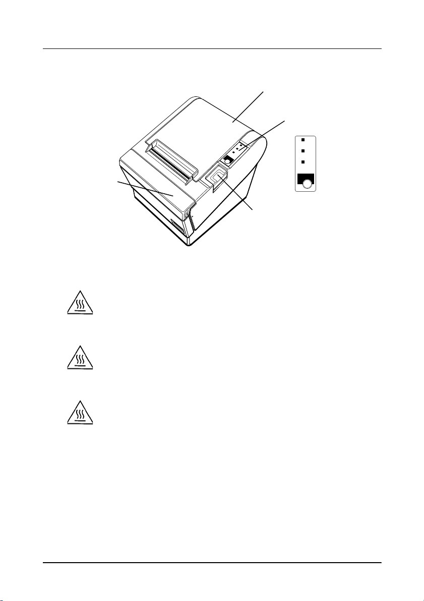
Printer Part s and Labels
Printer cover
Control panel
Cutter cover
Caution Lables
CAUTION:
Thermal head is hot.
ATTENTION:
La téte thermique est chaude.
VORSICHT:
POWER
ERROR
PAPER
OUT
FEED
Cover open button
POWER
ERROR
PAPER
OUT
FEED
Der Thermalkopf ist heiß.
Page 3
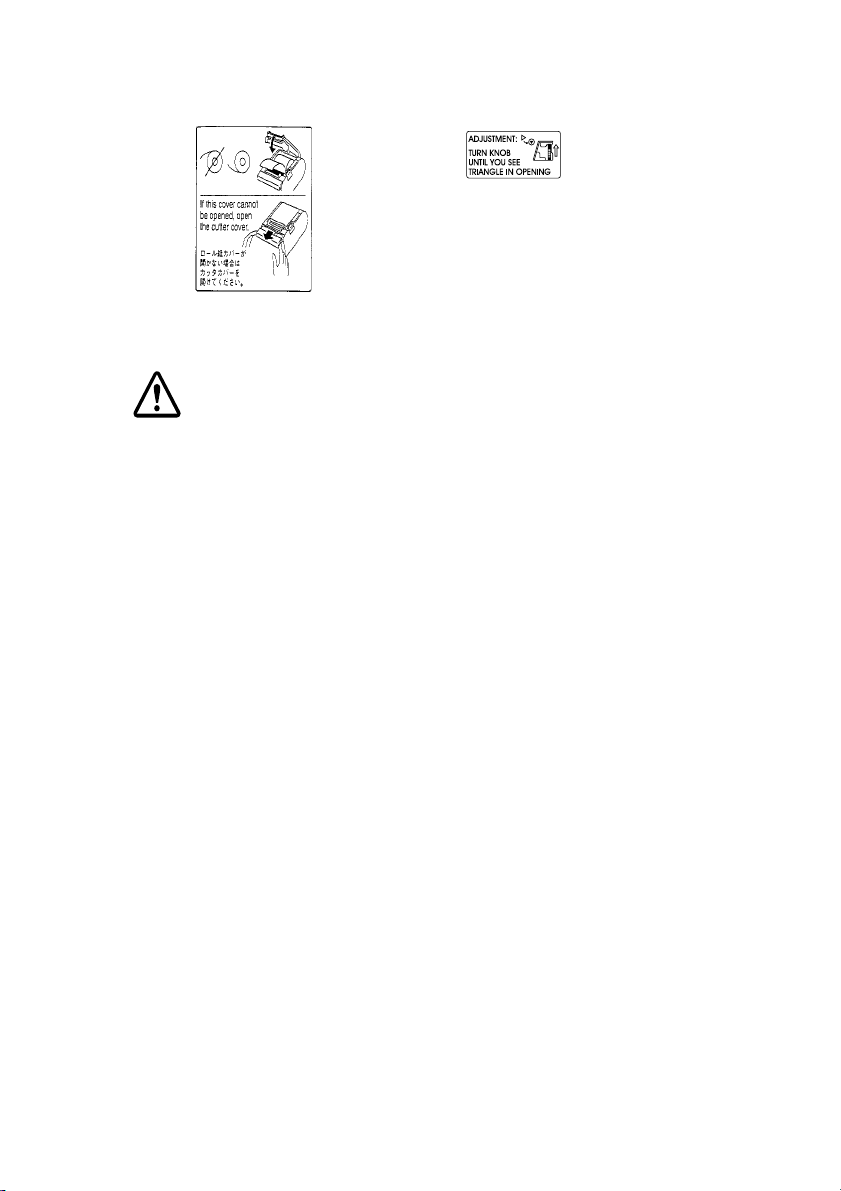
Labels
Label inside
cutter section
Label inside
printer cover
Caution label above drawer kick-out connector.
Page 4

Quick Reference
This Quick Reference will direct you to key areas of this Opera tor’ s
Manual. For a complete listing of topics, see the Contents.
Printer Parts and Labels inside front cover
Ordering Paper page ix
Where to order paper
Setting Up the Printer page 1-1
How to set up the printer.
Installing and Replacing Paper page 1-7
How to load or change the paper roll.
Solving Problems page 3-1
How to correct problems.
i
Page 5

All rights reserved. No part of this publication may be reproduced, stored in a
retrieval system, or transmitte d in any form o r by any means , electron ic, mecha nical,
photocopying, recording, or o therwise, without t he prior wri tten permission of Seiko
Epson Corporation. No patent liability is assumed with respect to the use of the
information contained herein. While every precaution has been taken in the
preparation of this book, Seiko Epson Corporation assumes no responsibility for
errors or omissions. Neither is any liability assumed for damages resulting from the
use of the information contained herein.
Neither Seiko Epson Corporation nor its affiliates shall be liable to the purchaser of
this product or third parties for damages, losses, costs, or expenses incurred by
purchaser or third parties as a result of: accident, misuse, or abuse of this product or
unauthorized modifications, repairs, or alterations to this product, or (excluding the
U.S.) failure to strictly comply with Seiko Epson Corporation’s operating and
maintenance instructions.
Seiko Epson Corporation shall not be liable again st any damage s or problems arising
from the use of any options or any cons umable pr oducts other than those desig nated
as Original Epson Produ cts or Epson Approved Pr oducts by Seik o Epson
Corporation.
EPSON is a registered trademark of Seiko Epson Corporation.
ESC/POS is a registered trademark of Seiko Epson Corporation.
NOTICE:
Copyright © 1997 by Seiko Epson C orporation, Nagano, Japan.
The contents of this manual are subject to change without notice.
ii
Page 6

FCC CLASS A
FCC Compliance Statement
For American Users
This equipment has been tested and found to comply with the limits for a Class A
digital device, pursuant to Part 15 of the FCC Rules. These limits are designed to
provide reasonable protection against harmful interference when the equipment is
operated in a commercial environment.
This equipment generates, uses, and can radiate radio frequency energy and, if not
installed and used in accordance with the instruction manual, may cause harmful
interference to radio communications. Operation of this equipment in a residential
area is likely to cause harmful interferenc e, in wh ich case the user will be required to
correct the interference at his own expense.
WARNING
The connection of a non-s hielded printer i nterface cable to th is printer w ill invalidat e
the FCC Verification of this device and may cause interference levels which exceed
the limits established by the FCC for this equipment.
You are cautioned that changes or modifications not expressly approved by the
party responsible for compliance could void your authority to operate the
equipment.
FOR CANADIAN USERS
This Class A digital apparatus meets all requirements of the Canadian InterferenceCausing Equipment Regulations.
Cet appareil numérique de la classe A respecte toutes les exigenves du Règlement
sur le matériel brouileur du Canada.
GEREÄUSCHPEGEL
Gemäß der Dritten Verordnung zum Gerätesicherheitsgesetz
(Maschinenlärminformations- Verordnung-3. GSGV) ist der arbeitsplatzbezogene
Geräusch-Emissi on swert kleiner als 70 dB(A) (basierend auf ISO 7779).
iii
Page 7

DECLARATION OF CONFORMITY
Product Name: Printer
Model Name: M129B
The printer conforms to the following Directives and Norms
Directive 89/336/EEC
EN 55022 (1987 and 1994 2nd/1995) Class B
EN 50082-1 (1992)
IEC 801-2 (1991)
IEC 801-3 (1984)
IEC 801-4 (1988)
Directive 90/384/EEC
EN45501: (1992)
iv
Page 8

EMI and Safety Standards Applied
The following standards are applied only to the printers that are so
labeled. (EMC is tested using the EPSON PS-170 power supply)
Europe: CE marking
EN55022
EN50082-1
EN45501
Safety Standard: TÜV (EN 60950)
North America: EMI: FCC Class A
Safety standards: UL 1950-2TH-D3
C-UL
Japan: EMI: VCCI Class 1
Oceania: EMI: AS/NZS 3548 Class B
v
Page 9
About This Manual
Setting Up and Using
❏ Chapter 1
❏ Chapter 2
❏ Chapter 3
contains information on unpacking the printer and setting it up.
contains information on using the printer.
contains troubleshooting information.
Reference
❏ Chapter 4
❏ Appendix A
and
contains specifications.
tells how to change the DIP switch and paper near end settings,
Appendix B
lists the EPSON Sales Subsidiaries and their addresses.
Warnings, Cautions, and Notes
WARNING:
Warnings must be followed carefully to avoid serious bodily
injury.
CAUTION:
Cautions must be observed to avoid minor injury to yourself or
damage to your equipment.
Note:
Notes have important information and useful tips on the operation of your
printer.
vi
Page 10

Introduction
Features
The TM-T88 II Series are high-quality POS printers that can print on a paper roll. The
printers have the following features:
Printing
High speed printing: 28.4 lines/second (1/6 inch feed) maximum.
❏
Low-noise thermal printing .
❏
High reliability due to a stable mechanism.
❏
Application Software
Command protocol is based on the ESC/POS™ standard.
❏
Various layouts are possible by using page mode.
❏
Characters can be scaled up to 64 t i me s a s la rge as the stand ar d siz e . S m oothing
❏
is also possible.
Bar code printing is possible by using a bar code command. Bar codes can be
❏
printed both in the vertical direction (fence bar code) and in the horizontal
direction (ladder bar code).
Repeated operation and copy printing are possible by using macro definitions.
❏
Character fon t size (12 x 24 f ont o r 9 x 17 f ont ) c an be selected using a c o mm an d .
❏
Printer Handling
Easy paper roll loading.
❏
An auto-cutter is standard.
❏
The printer allows easy maintenance for tasks such as head cleaning.
❏
Four different print densities can be selected by DIP switches.
❏
The built-in interface provides control capability for two drawers.
❏
Introduction vii
Page 11

Available non-volatile bit image buffer (256K bytes)
❏
Options and Accessories
EPSON power supply unit, PS-170.
❏
Affixing tapes (model : DF-10).
❏
RS-485 interface board can be equ ip ped as a dealer option.
❏
Wall hanging bracket set (WH-10)
❏
viii Introduction
Page 12

Ordering Paper an d Supplies
Thermal roll paper can be ordered from the supplier in your area.
Specified Thermal Roll Paper: NTP080-80
In Japan: Nakagawa Seisakujo
2-5-21 Nishiki-Cho Warabi-Shi
Saitama-Ken 335 Japan
Tel: (048) 444-8211
Fax: (048) 443-6652
In U.S.A.: Nakagawa Mfg (USA) Inc.
2305 Lincoln Avenue
Hayward, CA 94545 USA
Tel: (510) 782-0197
Fax: (510) 782-7124
In Europe: Nakagawa Mfg (Europe) GmbH.
Krützpoort 16, 47804
Krefeld, Germany
Tel: 02151-711051
Fax: 02151-713293
In Southeast Asia: N.A.K. Mfg (Malaysia) SDN BHD
Lot 19-11, Bersatu Industrial Complexs,
Jalan Satu, Kaw Per. Cheras Jaya,.
Balakong Industrial Area, 43200 Cheras.
Selangor Darul Ehsan, Malaysia
Tel: 03-9047896, 9047900, 9047691
Fax: 03-9047889
Introduction ix
Page 13

Other Qualified Suppliers for Thermal Paper
The followin g suppliers sell thermal paper that may be used if
desired. Contact each company for information.
Original paper: TF50KS-E
Nippon Paper Industry Co., Ltd.
1-12-1, Yuraku-Cho, Chiyoda-Ku
Tokyo 100 Japan
Tel: 03-3218-8000
Fax: 03-3216-1375
Original paper: PD 160R
New Oji Paper Mfg. Co., Ltd.
7-5 Ginza 4-Chome Chuo-Ku
Tokyo 104 Japan
Tel: 03-3563-4800
Fax: 03-3563-1136
Original paper: AF50KS-E
Jujo Thermal Oy (Finla nd)
P.O. Box 92 FIN27501 Kauttua Finland
Original paper: P350(F380)
x Introduction
Tel: 38-3932900
Fax: 38-3932419
P310
Kanzaki Specialty Papers, Inc.
1500 Main Street
Springfield, MA 01115 U.S.A.
Tel: (413)736-3216
Fax: (413)734-5101
Page 14

Contents
Quick Reference. . . . . . . . . . . . . . . . . . . . . . . . . . . . . . . . . . . . . . . . . . . . . . . . . . . . . . . . i
Introduction . . . . . . . . . . . . . . . . . . . . . . . . . . . . . . . . . . . . . . . . . . . . . . . . . . . . . . . . . . . vii
Chapter 1
Unpacking . . . . . . . . . . . . . . . . . . . . . . . . . . . . . . . . . . . . . . . . . . . . . . . . . . . . . . . . . . . . 1-1
Connecting the Cables and Grounding the Printer . . . . . . . . . . . . . . . . . . . . . . . . . . 1-2
Installing or Replacing the Paper Roll . . . . . . . . . . . . . . . . . . . . . . . . . . . . . . . . . . . . . 1-7
Using the Power Switch Cover . . . . . . . . . . . . . . . . . . . . . . . . . . . . . . . . . . . . . . . . . . . 1-10
Self Test . . . . . . . . . . . . . . . . . . . . . . . . . . . . . . . . . . . . . . . . . . . . . . . . . . . . . . . . . . . . . . 1-10
Running the self test . . . . . . . . . . . . . . . . . . . . . . . . . . . . . . . . . . . . . . . . . . . . . . . 1-10
Adjustments and Settings . . . . . . . . . . . . . . . . . . . . . . . . . . . . . . . . . . . . . . . . . . . . . . . 1-12
Chapter 2
Operating the Control Panels . . . . . . . . . . . . . . . . . . . . . . . . . . . . . . . . . . . . . . . . . . . . 2-1
Control Panel . . . . . . . . . . . . . . . . . . . . . . . . . . . . . . . . . . . . . . . . . . . . . . . . . . . . . 2-1
Panel Lights . . . . . . . . . . . . . . . . . . . . . . . . . . . . . . . . . . . . . . . . . . . . . . . . . . . . . . . 2-2
Chapter 3
Troubleshooting . . . . . . . . . . . . . . . . . . . . . . . . . . . . . . . . . . . . . . . . . . . . . . . . . . . . . . . 3-1
General problems . . . . . . . . . . . . . . . . . . . . . . . . . . . . . . . . . . . . . . . . . . . . . . . . . . 3-1
Printing problems . . . . . . . . . . . . . . . . . . . . . . . . . . . . . . . . . . . . . . . . . . . . . . . . . . 3-1
Cleaning the print head . . . . . . . . . . . . . . . . . . . . . . . . . . . . . . . . . . . . . . . . . . . . . 3-3
Paper handling problems . . . . . . . . . . . . . . . . . . . . . . . . . . . . . . . . . . . . . . . . . . . 3-3
Auto cutter problems . . . . . . . . . . . . . . . . . . . . . . . . . . . . . . . . . . . . . . . . . . . . . . . 3-5
Hexadecimal Dump . . . . . . . . . . . . . . . . . . . . . . . . . . . . . . . . . . . . . . . . . . . . . . . . . . . . 3-7
Setting Up the Printer
Using the Printer
Troubleshooting
xi
Page 15

Chapter 4
Printing Specifications . . . . . . . . . . . . . . . . . . . . . . . . . . . . . . . . . . . . . . . . . . . . . . . . . . 4-1
Paper Specifications . . . . . . . . . . . . . . . . . . . . . . . . . . . . . . . . . . . . . . . . . . . . . . . . . . . . 4-3
Electrical Characteristics . . . . . . . . . . . . . . . . . . . . . . . . . . . . . . . . . . . . . . . . . . . . . . . . 4-4
Reliability . . . . . . . . . . . . . . . . . . . . . . . . . . . . . . . . . . . . . . . . . . . . . . . . . . . . . . . . . . . . . 4-5
Environmental Conditions . . . . . . . . . . . . . . . . . . . . . . . . . . . . . . . . . . . . . . . . . . . . . . 4-5
Reference Information
Appendix A
Setting the DIP Switches . . . . . . . . . . . . . . . . . . . . . . . . . . . . . . . . . . . . . . . . . . . . . . . . A-1
Adjusting the Paper Near End Sensor . . . . . . . . . . . . . . . . . . . . . . . . . . . . . . . . . . . . . A-8
Appendix B
DIP Switch and Paper Near End Settings
EPSON Sales Subsidiaries
xii
Page 16

Chapter 1
Setting Up the Printer
Unpacking
Your printer box should include these items. If any items are
damaged or missing, please contact your dealer for assistance.
Printer
POWER
ERROR
PAPER
OUT
FEED
Paper roll
Hexagonal
lock screws
Switch cover
See the note on page 1-3 for information about the hexagonal lock screws.
Setting Up the Printer 1-1
Page 17

Connecting the Cables and Grounding the Printer
hsa a parallel interface.)
You can connect up to four cables to the printer. They all connect to
the connector panel on the back of the printer, which is shown
below:
FG
Interface
(The shape of the interface
connector is different from
the illustration if th e printer
FG
Grounding screw
DC24V
DK
Drawer kick-out
Power supply
Notes:
There is a caution label above the drawer kick-out connector.
Depending on the interface installed, the interface connector on
your printer may look different from the one illustrated.
Before connecting any of the cables, make sure that both the printer
and the computer are turned off.
Connecting the computer
You need an appropriate interface cable.
1. Plug the cable connector securely into the printer’s interface
connector.
1-2 Setting Up the Printer
Page 18

2. If the printer h as a serial interface, tighten the screws on both
sides of the cable connector.
Note:
Your printer has inch-type hexagonal lock screws installed. If
your interface cable requires millimeter-type screws, replace the
inch-type screws with the enclosed millimeter-type screws using
a hex screwdriver (5 mm).
Inch screw
If the printer has a parallel interface, squeeze the wire clip on
the printer to gether until they lock in place on both sides of the
connector.
3. Attach the other end of the cable to the computer.
Millimeter screw
Connecting the Drawer
WARNING:
Use a drawer that matches the printer sp ecifi cat ion. Using an
improper drawer may damage the drawer as well as the
printer.
CAUTION:
Setting Up the Printer 1-3
Page 19

Do not connect a telephone line to the drawer kick-out
connector; otherwise the printer and the telephone line may
be damaged.
Plug the drawer cable into the drawer kick-out connector on the
back of the printer next to the power supply connector.
Anschließen der Lade
WARNUNG:
Eine für den Drucker geeignete Lade verwenden. Bei
Verwendung einer falschen Lade kann diese oder der
Drucker beschädigt werden.
ACHTUNG:
Kein Telefonkabel an die Schnappsteckerbuchse
anschließen, da sonst der Drucker und die Telefonkabel
beschädigt werden können.
1-4 Setting Up the Printer
Page 20

Das Kabel der Lade an die Schnappsteckerbuchse hinten am
Drucker neben dem Netßzanschluß
anschließen
.
Grounding the Printer
You need a ground wire to gr ound your pr inter. Make sure that t he
wire is AWG 18 or equivalent.
1. Make sure that the printer is turned off.
2. Connect the ground wire to the printer using one of the the FG
screws on the back of the printer, as shown.
FG
FG
DC24V
DK
Connecting the Power Supply
Use the optional EPSON PS-170 or equivalent power supply for
your printer.
Setting Up the Printer 1-5
Page 21

WARNING:
Make sure that you use the EPSON PS-170 power supply or
equivalent. Using an i ncorrect power supply may cause fir e or
electrical shock.
CAUTIONS:
When connecting or disconnecting the power supply from
the printer, make sure that the power supply is not plugged
into an electrical outlet. Otherwise you may damage the
power supply or the printer.
If the power supply’s rated voltage and your outlet’s voltage
do not match, contact your dealer for assistance. Do not
plug in the power cord. Otherwise, you may damage the
power supply or the printer.
1. Make sure that the printer’s power switch is turned off, and the
power supply’s power cord is unplugged from the electrical
outlet.
2. Check the label on the power supply to make sure that the
voltage required by the power supply matches that of your
electrical outlet.
3. Plug in the power supply’s cable as shown below. Notice that
the flat side of the plug faces down.
Note:
To remove the DC cable connector, make sure that the power
supply’s power cord is unplugged; then grasp the connector at the
arrow and pull it straight out.
1-6 Setting Up the Printer
Page 22

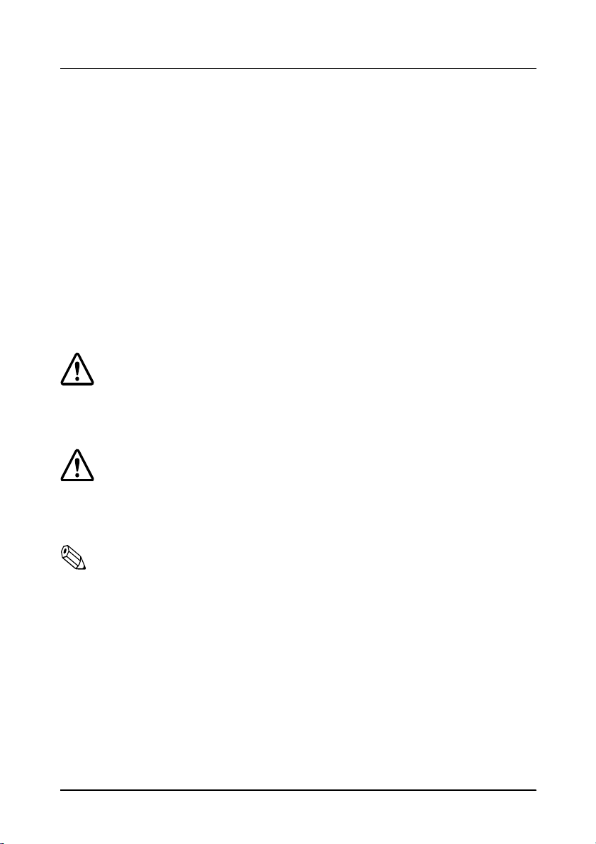
Installing or Replacing the Paper Roll
Note:
Be sure to use paper rolls that meet the specifications. Do not
use paper rolls that have the paper glued to the core because the
printer cannot detect the paper end correctly.
1. Make sure that the printer is not receiving data; oth erwise, data
may be lost.
2. Open the paper roll cover by pressin g the cover -ope n button. If
the cover-open button will not open the cover, see page 3-4 or
3-6 in Troubleshooting.
POWER
ERROR
PAPER
OUT
FEED
3. Remove the used paper roll core if there is one.
Setting Up the Printer 1-7
Page 23

4. Insert the paper roll as shown.
POWER
ERROR
PAPER
OUT
FEED
5. Be sure to note the correct direction t hat the paper comes off the
roll.
1-8 Setting Up the Printer
Page 24
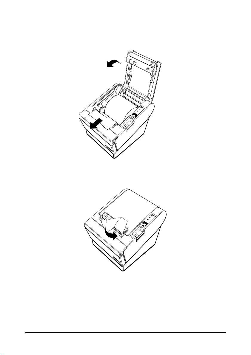
6. Pull out a small amount of paper, as shown. Then close the
ERROR
POWER
PAPER
OUT
FEED
cover.
7. Tear off the paper as shown.
POWER
ERROR
PAPER
OUT
FEED
Setting Up the Printer 1-9
Page 25
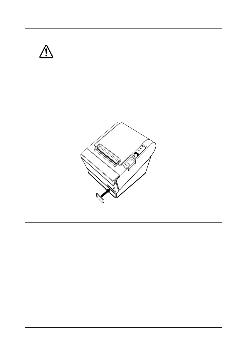
Using the Power Switch Cover
WARNING:
If an accident occurs when the power switch cover is
attached, unplug th e power supply cord from the outlet
immediately. Continued usage may lead to fire or shoc k.
You can use the enclosed power swit ch cover to make sure that the
power switch is not accidentally pressed. If you want to use this
cover, install it as shown in the illustration below.
POWER
ERROR
PAPER
OUT
FEED
Self Test
The self test lets you know if your printer is operati ng properly. It
checks the control circuits, pri nter mechanisms, print qual ity, ROM
version, and DIP switch settin gs.
This test is independent of any other equipment or software.
Running the self test
1. Make sure the printer is turned off and the printer covers are
closed properly.
1-10 Setting Up the Printer
Page 26

2. While holding down the FEED button, turn on the printer using
the switch on the front of the printer to begin the self test. The
self test prints the printer settings and then prints the
following, cuts the paper, and pauses. (The PAPER OUT light
blinks.)
Self test printing.
Please press the PAPER FEED button.
3. Press the FEED button to continue pri nting. T he print er prin ts a
pattern using the built-in character set.
4. The self test automatically ends and cuts the paper after
printing the fo llowing:
*** completed ***
The printer is ready to receive data as soon as it completes the self
test.
Note:
If you want to pause the self test manually, press the FEED
button. Press the FEED button again to continue the self test.
Setting Up the Printer 1-11
Page 27

Adjustments and Settings
The TM-T88II Series are set up at the factory to be appropriate for
almost all users. It does, however, offer some settings for users with
special requirements.
It has DIP switches that allow you to change communication
settings, such as handshaking and parity check, as well as print
density.
The TM-T88II Series also have a near-end sensor for the paper. This
can give you a warning when the paper is almost out. If you find
that there is not enough paper remaining on the rol l when t he nearend detector is triggered, you can change the near-end sensor
setting.
See Appendix A if you need to make any of these changes.
1-12 Setting Up the Printer
Page 28

Chapter 2
Using the Printer
Operating the Control Panels
You can control the basic paper feeding operations of the printer
with the button on the control panel. The indicator lights help you
monitor the printer’s status.
Control Panel
POWER
ERROR
PAPER
OUT
FEED
Button
The button can be disabled by the ESC c 5 command.
Press the FEED button once to advanc e paper one line . You can al so
hold down the FEED button to feed paper continuously.
Using the Printer 2-1
Page 29

Panel lights
POWER
The POWER light is on whenever the printer is o n.
ERROR
This indicates an error. See Chapter 3 for informati on on what to do
when this light comes on.
PAPER OUT
This light indicates the near end of the paper roll . Install a new
paper roll and the printer will continue printing.
When the light blinks, it indicates the self-test printing standby
state or macro execution standby state when the macro execution
command is used.
2-2 Using the Printer
Page 30

Chapter 3
Troubleshooting
Troubleshooting
This chapter give s solutions to some prin ter problems you may
have.
General problems
The lights on the control panel do not come on.
Make sure that the power supply cables are correctly plugged into
the printer, the power unit, and to the power outlet.
Make sure tha t power is supp lied to the power outlet. If the outlet
is controlled by a switch or timer, use another outlet.
Printing problems
ERROR
The
The
ERROR
light is on (not blinking) and nothing is printed.
If the PAPER OUT light is on, the pa per roll is not installed or is at
or near the end. Install a new paper roll. See Chapter 1 for
instructions.
If the PAPER OUT light is off, make sure that the printer c over is
properly closed. Press the printer cover until the cover audibly
clicks into place.
light is blinking and the printer does not print.
First, turn off the printer and check for a paper jam. (See the paper
jam description on page 3-3.)
Troubleshooting 3-1
Page 31

If there is no paper jam and the printer has been printing for quite a
while, the print head may be overheated. If the print head is
overheated, the printer will resume printing when the head has
cooled (usually within two or three minutes).
If there is no paper jam and the print head is not overheated, turn
off the printer a nd turn it back on after about 10 seconds. If the
ERROR light is still flashing, contact a qual ified service person.
ERROR
The
light is off, but nothing is printed .
Try to run the self test to check that the printer works pro perly . See
the self test instructions in Chapter 1 to run the self test. If the self
test does not work, contact your dealer or a qualified service
person.
If the self test works properly, check the following:
1. Check the connection at both ends of the interface cable
between the printer and the computer. Also make sure that this
cable meets the specifications for both the printer and the
computer.
2. The data transmission settings may be different between the
printer and co mputer. Make sure that the printe r’s DIP switch
settings for data transmission are the same as the computer’s.
You can print the printer’s interface settings using the self test.
If the printer still does not print, contact your dealer or a qualified
service person.
Printing is poor.
Paper dust on the heating element of the thermal print head can
lower the print quality. Try cleaning the print head as described
below:
3-2 Troubleshooting
Page 32
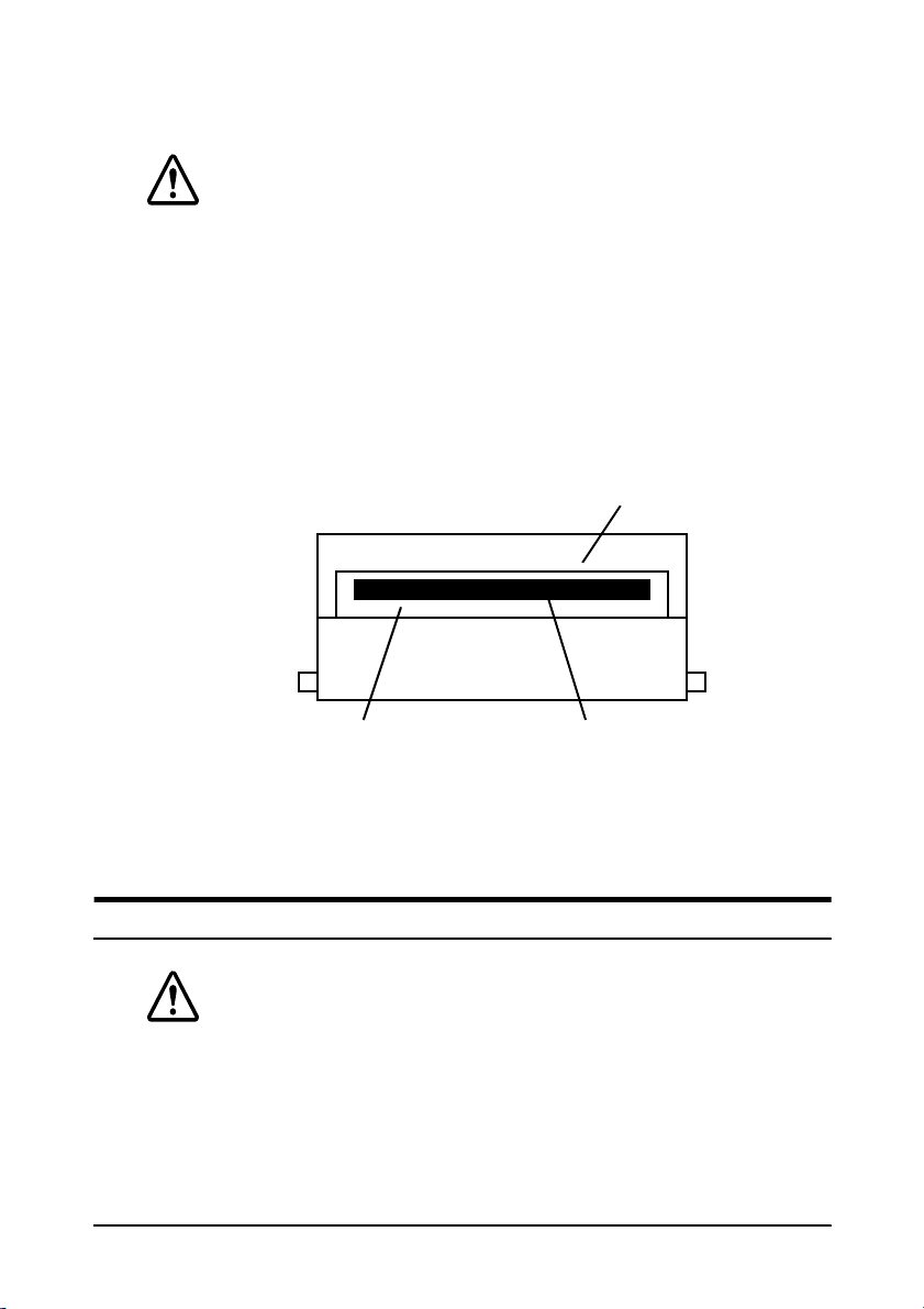
Cleaning the print head
CAUTIONS:
After printing, the print head can be very hot. Be careful not
to touch it. Also let it cool before you clean it.
Do not damage the print head by touching it with your
fingers or any hard object.
1. Open the printer cover.
2. Clean the thermal element of the print head with a cott on swab
moistened with an alcohol solvent (ethanol, methanol, or IPA).
Radiation plate
Head
Thermal element
Paper handling problems
Paper is jammed inside the printe r.
CAUTIONS:
Do not touch the print head because it can be very hot after
printing continuously for a long time.
Troubleshooting 3-3
Page 33

To clear a paper jam, follow the steps below:
1. Turn the printer off and press the cover open button to open
the cover.
2. Remove the jammed paper and put the roll back in the printer
and close the cover.
3. If paper is caught in the automatic cutter and the printer cover
cannot be opened, open the cutter cover as shown below.
POWER
ERROR
PAPER
OUT
FEED
3-4 Troubleshooting
Page 34

4. Then turn the knob until you see in the opening, as shown in
the illustration below. This returns the cutter blade to the
normal position. Also notice that there is a label near the cutter
to assist you.
ADJUSTMENT:
TURN KNOB
UNTIL YOU SEE
TRIANGLE IN OPENING
POWER
ERROR
PAPER
OUT
FEED
5. Close the cutter cover.
6. Open the printer cover.
7. Remove the jammed paper.
Auto cutter problems
The auto cutter is jammed.
If a foreign obje ct such as a push pin or paper c lip d rops i n the aut o
cutter and causes the auto cutter to lock up, the printer enters an
error state and begins the recovery operation automatically.
If the problem is not serious, the auto cutter returns to its normal
position without any intervention by the user.
Troubleshooting 3-5
Page 35

If the auto cutter does not return to its normal position by itself,
follow the steps below to correct the problem:
1. Pull the cutter cover toward you so that you can rotate the
cutter motor knob.
POWER
ERROR
PAPER
OUT
FEED
2. Following the instructions on the label, rotate the knob until the
appears in the hole.
ADJUSTMENT:
TURN KNOB
UNTIL YOU SEE
TRIANGLE IN OPENING
3. Close the cutter cover.
3-6 Troubleshooting
POWER
ERROR
PAPER
OUT
FEED
Page 36

Hexadecimal Dump
This feature allows experienced users to see exactly what data is
coming to the printer. This can be useful in finding software
problems. When you turn on the hex dump function, the printer
prints all commands and other data in hexadecimal format along
with a guide section to help you find specific commands.
To use the hex dump feature, follow these steps:
1. After you make sure that the printer is off, open the cover.
2. Hold down the FEED button while you turn on the printer.
3. Close the cover.
4. Run any software program that sends data to the printer. The
printer prints “Hexadecimal Dump” and then all the codes it
receives in a two-column format. The first column contains the
hexadecimal codes and the second column gives the ASCII
characters that correspond to the codes.
Hexadecimal Dump
1B 21 00 1B 26 02 40 40 . ! . . & . @ @
1B 25 01 1B 63 34 00 1B . % . . c4 . .
41 42 43 44 45 46 47 48 ABCDEFGH
A period (.) is printed for each code that has no ASCII
❏
equivalent.
During the hex dump all commands except DLE EOT and
❏
DLE ENQ are disabled.
5. Open the cover to set the printer off line so that it will print the
last line.
6. Close the cover and turn o ff the p rinte r or r eset it to tur n off t he
hex dump mode.
Troubleshooting 3-7
Page 37

Chapter 4
Reference Info rm ation
Printing Specifications
Printing method: Thermal line printing
×
Dot density: 180 dpi
25.4 mm (1”)]
Printing direction: Unidirectional with fr iction feed
Printing width: 72 mm (2.83”), 512 dot positions
180 dpi [the number of dots per
Characters per line
(default):
Character spacing
(default):
Printing speed High speed mode:
Printing speed Low power
comsumption mode:
Printing speed when a ladder bar
code is printed:
42 (Font A)
56 (Font B)
0.28 mm (.01”) (2 dots) (Font A)
0.28 mm (.01”) (2 dots) (Font B)
Programmable by control command.
28.4 lines/second maximum
(1/6” feed, at 24V, 20° C,
density level 2)
Approximately 120 mm/second
maximum (approximately 4.72”/second
maximum)
Speed is adjusted deepening on the
applied voltage to the printer and head
temperature conditions automatically.
Approximately 16.5 lines/second (1/6”
feed)
Approximately 70 mm/second
(approximately 2.76”/second)
Approximately 42 mm/ second
(approximately 1.7’’/ second)
Reference Information 4-1
Page 38

Notes:
Printing speed may be slower, depending on the data transmission
speed and the combination of control commands.
There may be variations in printing after switching the mode of the
printing speed. To prevent this for lo go printing, using a
downloaded bit image is recommended. (Change in printing speed
does not occur during downloaded bit image printing).
Paper feeding speed: Approximately 120 mm/second
(approximately 4.72”/second) continuous
paper feeding
Line spacing (default): 4.23 mm (1/6”)
Programmable by control command.
Number of characters: Alphanumeric characters: 95
Internati onal characters: 32
×
Extended graphics: 128
7 pages
(including one space page)
kanji chareacters: JIS-Level 1, Level 2
(JIS X0208-1990)
Character structure: Font A: 12
4-2 Reference Information
×
24 (including 2-dot spacing
in horizontal)
Font B: 9
×
17 (including 2-dot spacing in
horizontal)
Kanji: 24
× 24
Font A is the default
Page 39

CPL
80±
0.5
1.0
mm 3.15’’±
0.02’’
0.04’’
21
28
10
Double-width/
Double-height
W x H
(mm)
2.82 x 6.77
(.11” x .27”)
1.98 x 4.80
(.08” x .19”)
6.77 x 6.77
(.27’’x.27’’)
Font A
12 x 24
Font B
9 x 17
Kanji
24 x 24
Standard Double-height Double-width
42
56
21
W x H
(mm)
2.82 x 3.39
(.11” x .13”)
1.98 x 2.40
(.08” x .09”)
6.77 x 3.39
(.27’’x.13’’)
W x H
(mm)
1.41 x 3.39
(.06” x .13”)
0.99 x 2.40
(.04” x .09”)
3.39 x 3.39
(.13’’x.13’’)
CPL
42
56
21
W x H
(mm)
1.41 x 6.77
(.06” x .27”)
0.99 x 4.80
(.04” x .19”)
3.39 x 6.77
(.13’’x.27’’)
CPL
* CPL = Characters Per Line
* Space between characters is not included
* Characters can be scaled up to 64 times as large as the standard sizes.
Paper Specifications
Paper roll (single-ply): Size: Width: 79.5 mm ± 0.5 mm
(3.13” ± 0.02”)
CPL
21
28
10
Maximum
outside
diameter:
Paper roll
spool
diameter:
Take up
paper roll
width:
83 mm (3.27”)
Inside: 12 mm (0.47”)
Outside: 18 mm (0.71”)
Paper must not be pasted
to the paper roll spool.
Reference Information 4-3
Page 40

Electrical Characteristics
Supply voltage: +24 VDC ± 7% (optional power supply: EPSON
PS-170)
Current
consumption: (at
24V)
Low power
Note:
Maximum 1A for drawer kick-out driving
High speed
mode:
consumption
mode:
Standby: Mean: Approximately 0.2A
Mean: Approximately 1.7A
(character font A α-N all
columns printing)
Peak: Approximately 7.7A
Mean: Approximately 1.2A
(Character font A α-N all
colums printing)
Peak: Approximately 6.6A
4-4 Reference Information
Page 41

Environmental Conditions
Temperature: Operating: 5° to 45°C (41° to 113°F)
Storage: -10° to 50°C (14° to 122°F)
(except for paper)
Humidity: Operating: 10 to 90% RH
Storage: 10 to 90% RH (except for
paper)
Reference Information 4-5
Page 42

Appendix A
Dip Switch and Paper Near End Settings
Although the factory settings are best for almost all uses, if you
have special requiremen ts, you c an change the DIP switch or paper
near end settings.
Setting the DIP Switches
DIP switch functions
Your printer has two sets of DIP switches. The functions of the
switches are shown in the following tables.
Serial interface specification
Set 1
SW Function ON OFF
1-1 Data receive error Ignored Prints “?”
1-2 Receive buffer capacity 45 bytes 4K bytes
1-3 Handshaking XON/XOFF DTR/DSR
1-4 Data word length 7 bits 8 bits
1-5 Parity check Enabled Disabled
1-6 Parity selection Even Odd
1-7
Transmission speed (See the table below)
1-8
Dip Switch and Paper Near End Settings A-1
Page 43

Transmission Speed
Transmission Speed (BPS)-bits per second 1-7 1-8
2400 ON ON
4800 OFF ON
9600 ON OFF
19200 OFF OFF
Set 2
SW Function ON OFF
Handshakin g (B USY
2-1
condition)
Reserved: do not
2-2
change settings
2-3
Selects print density Refer to table below
2-4
Reserved: do not
2-5
change settings
Reserved: do not
2-6
change settings
2-7 I/F pin 6 reset signal Enabl ed Disabled
2-8 I/F pin 25 reset signal Enabled Disabled
Receive buffer full
Fixed to OFF
Fixed to OFF
Fixed to OFF
Off line or
receive buffer full
A-2 Dip Switch and Paper Near End Settings
Page 44

Print Density Selection
Print Density SW 2-3 SW 2-4
1 Low power comsumption mode ON ON
2(Normal) O F F OFF
3ONOFF
4 (Dark) OFF ON
Notes:
With the optional RS-485 interface, DIP switches 2-7 and 2-8 are disabled.
•
Changes in DIP switch settin gs (excluding switches 2-7 and 2-8 inte rface reset
•
signals) are recognized only when the printer power is turned on or when the
printer is reset by using the i nterface. If the DIP switch setting is changed after
the printer power is turned on, the change do es not take effect until the
printer is turned on again or is reset.
If you turn on DIP switch 2-7 or 2-8 while the printer is turned on, the printer may
•
be reset, depending on the signal state. DIP switches should not be changed
while the printer power is on.
If the print density is set to level 3 or 4, the printing will be at the low speed.
•
In a low power consuption, printing speed is fixed to 70 mm/sec.
•
Dip Switch and Paper Near End Settings A-3
Page 45

Parallel interface specification
Set 1
SW Function ON OFF
1-1 Auto line feed Always enabled Always disabled
1-2 Receive buffer capacity 45 bytes 4K bytes
1-3~
1-8
Set 2
SW Function ON OFF
2-1
2-2
2-3
2-4
2-5~
2-7
2-8
Undefined – –
Handshaking
(BUSY condit io n)
Reserved
(Do not cha nge settings )
Selects print density Refer to table below
Reserved
(Do not cha nge settings )
I/F pin 31 reset signal
(Do not cha nge settins)
•
Receive buffer full
•
Reading data
Fixed to Off
Fixed to Off
Fixed to On
•
Off-line
•
Receive buffer full
•
Reading data
Print Density Selection
Print Density SW 2-3 SW 2-4
1 Low power consumption mode ON ON
2 (Normal) OFF ON
3ONOFF
4 (Dark) OFF OFF
A-4 Dip Switch and Paper Near End Settings
Page 46

Notes:
Changes in DIP switch settings (excluding switch 2-8 interface reset signal) are
•
recognized only when the printer po wer is turne d on or wh en the prin ter is
reset by using the interface. If the DIP switch setting is changed after the
printer power is turned on, the change do es not take effect until the printer is
turned on again or is reset.
If you turn on DIP switch 2-8 while the printer is turned on, the printer may be
•
reset, depending on the signal state. DIP switches should not be changed
while the printer power is on.
If the print density is set to level 3 or 4, the printing will be at the low speed.
•
In a low power consumption, printing is fixed to 70mm/sec.
•
Dip Switch and Paper Near End Settings A-5
Page 47

Changing the DIP switch settings
If you need to chang e settings, foll ow the steps belo w to mak e your
changes:
CAUTION:
Turn off the printer while removing the DIP switch cover to
prevent an electric short, which can damage the printer.
1. Make sure the printer is turned off.
2. Remove the screw from the DI P swi tch cov er. Then take off the
DIP switch cover, as shown in the illustration below.
DSW1
DSW2
3. Set the switches using a pointed tool, such as tweezers or a
small screwdriver.
4. Replace the DIP switch cover. Then secure it with the screw.
The new settings take effect when you turn on the printer.
A-6 Dip Switch and Paper Near End Settings
Page 48

Adjusting the Paper Near End Detector
The paper near end detector detects when paper is almost gone by
measuring the diameter of the paper roll. The detector has two
settings.
Because of variations in paper roll cores, it is not possible for the
detector to measure exa ctly the length o f paper left on the roll when
the detector is triggered. Of the two settings, the factory setting
(lower) leaves the least amount of paper on the roll when the
sensor is triggered. If you want more paper left, c hange the setting
as described belo w.
Note:
The factory setting is based on a paper roll core with an outside
diameter of 18mm and an inside diameter of 12mm. If you use a
paper roll with a core with an outside diameter of more than 18mm,
it is better to change to the upper setting, as described below.
1. Open the printer cover, and remove the paper roll.
2. Loosen the adjusting screw and move the tab up to the upper
setting.
Tab
Screw
POWER
ERROR
PAPER
OUT
FEED
3. Tighten the adjusting screw, and check to be sure that the
detecting lever moves freely.
4. Replace the paper roll.
Dip Switch and Paper Near End Settings A-7
Page 49

Appendix B
EPSON
EPSON AMERICA INC./OEM DI V. 20770 Madrona Ave.
EPSON EUROPE B.V. Prof. J.H. Bavi ncklaan 5
EPSON Deutschland GmbH Zülpicher Strasse 6, 40549
EPSON U.K. LIMITED Campus 100 Maylands Ave.
EPSON FRANCE S.A. 68 Bis Rue Marjol i n B.P. 320 92305
Sales Subsidiaries
Torrance, CA 90559-2842 U.S.A.
Tel : 1-310-787-6300
Fax : 1-310-782-5350
1183 AT Amstelveen The Netherlands
Tel : 31-(0)20-5475-251
Fax : 31-(0)20-6454-315
Düsseldorf 11, Germany
Tel : 49-(0)211-5603152
Fax : 49-(0)211-5603319
Hemel Hempstead Herts. HP2 7TJ
United Kingdom
Tel : 44-1(0)442-61144
Fax : 44-1-(0)442-227-244
Levallois Perret Cedex, France
Tel : 33-(0)1-40-87-38-62
Fax : 33-(0)1-47-37-15-10
EPSON IBERICA, S.A. Avda. de Roma, 18-26
EPSON ITALIA S.P.A. V.le F IIi Casiraghi, 427
EPSON SINGAPORE PTE. LTD. No. 1 Raffles Place #26-00 OUB
08290 Cerdanyola del Vallès (Barcel ona), Spain
Tel : 34-(9)3-582-2500
Fax : 34-(9)(3-582-1555
20099 Sesto Si Giovanni (M il an), It al y
Tel : (39)226-2331
Fax (39)2244-0750
Centre Singapore, 0104
Tel : 5-530477
Fax : 5-5338119
EPSON Sales Subsidiaries B-1
Page 50

EPSON HONG KONG LIMITED 25/F., Harbor Centre, 25, Harbor Road,
EPSON TAIWAN TECHNOLOGY 10f, No. 287, Nanking E. Road, Sec. 3
& TRADING LTD. Taipei, Taiwan R.O.C.
SEIKO EPSON CORP. 10F, KIL 63 Buil ding 60,
KOREA OFFICE Yoid o Do ng, Youngedungpo-Ku,
EPSON AUSTRALIA PTY. LTD. 70 Gibbes Street, Chatswood NSW 2067
EPSON HANBAI CO., LTD.
TOKYO OFFICE: 3F Building Kawaguchi
Wanchai, Hong Kong
Tel : 852-2-585-4663
Fax : 852-2-827-4346
Tel : 886-(0)2-717 -7360
Fax : 886-(0)2-718-9366
Seoul, Korea
Tel : 82-(0)2-784-6027
Fax : 82-(0)2-769-1049
Australia
Tel : 61-(0)2-415-9000
Fax : 61-(0)2-417-0077
Fuda Chofu-Shi Tokyo 182 Japan
Tel : 0424-99-7829
Fax : 0424-99-7834
OSAKA OFFICE: 13F Shin-Osaka Daiichi-Seimei Bldg.
5-24 3-Chome Miyahara Yodo gawa-ku
Osaka 532 Japan
Tel : 06-350-4964
Fax : 06-350-4968
B-2 EPSON Sales Subsidiaries
 Loading...