

Page 1
®
SERVICE MANUAL
®
All-in-one printer, scanner, and copier
EPSON STYLUS Scan 2000
Page 2

EPSON STYLUS Scan 2000 Revision B
Notice:
All rights reserved. No part of this manual may be reproduced, stored in a retrieval system, or transmitted in any form or by any means,
electronic, mechanical, photocopying, recording, or otherwise, without the prior written permission of SEIKO EPSON CORPORATION.
The contents of this manual are subject to change without notice.
All effort have been made to ensure the accuracy of the contents of this manual. However, should any errors be detected, SEIKO EPSON
would greatly appreciate being informed of them.
The above not withstanding SEIKO EPSON CORPORATION can assume no responsibility for any errors in this manual or the consequences
thereof.
EPSON is a registered trademark of SEIKO EPSON CORPORATION.
General Notice: Other product names used herein are for identification purpose only and may be trademarks or registered trademarks of their
respective owners. EPSON disclaims any and all rights in those marks.
Copyright © 1999 SEIKO EPSON CORPORATION. Printed in Japan.
2
Page 3

EPSON STYLUS Scan 2000 Revision A
CAUTION
PRECAUTIONS
Precautionary notations throughout the text are categorized relative to 1) Personal injury and 2) damage to equipment.
W ARNING
Signals a precaution which, if ignored, could result in
damage to equipment.
Signals a precaution which, if ignored, could result
in damage to equipment.
DANGER
1. ALWAYS DISCONNECT THE PRODUCT FROM THE POWER SOURCE AND PERIPHERAL DEVICES PERFORMING ANY MAINTENANCE OR REPAIR
PROCEDURES.
2. NOWORK SHOULD BE PERFORMED ON THE UNIT BY PERSONS UNFAMILIAR WITH BASIC SAFETY MEASURES AS DICTATED FOR ALL
ELECTRONICS TECHNICIANS IN THEIR LINE OF WORK.
3. WHEN PERFORMING TESTING AS DICTATED WITHIN THIS MANUAL, DO NOT CONNECT THE UNIT TO A POWER SOURCE UNTIL
INSTRUCTED TO DO SO. WHEN THE POWER SUPPLY CABLE MUST BE CONNECTED, USE EXTREME CAUTION IN WORKING ON POWER
SUPPLY AND OTHER ELECTRONIC COMPONENTS.
WARNING
1. REPAIRS ON EPSON PRODUCT SHOULD BE PERFORMED ONLY BY AN EPSON CERTIFIED REPAIR TECHNICIAN.
2. MAKE CERTAIN THAT THE SOURCE VOLTAGES IS THE SAME A S THE RATED VOLTAGE, LISTED ON THE SERIAL NUMBER/RATING PLATE. IF
THE EPSON PRODUCT HAS A PRIMARY AC RATING DIFFERENT FROM AVAILABLE POWER SOURCE, DO NOT CONNECT IT TO THE POWER
SOURCE.
3. ALWAYS VERIFY THAT THE EPSON PRODUCT HAS BEEN DISCONNECTED FROM THE POWER SOURCE BEFORE REMOVING OR REPLACING
PRINTED CIRCUIT BOARDS AND/OR INDIVIDUAL CHIPS.
4. IN ORDER TO PROTECT SENSITIVE MICROPROCESSORS AND CIRCUITRY, USE STATIC DISCHARGE EQUIPMENT, SUCH AS ANTI-STATIC
WRIST STRAPS, WHEN ACCESSING INTERNAL COMPONENTS.
5. REPLACE MALFUNCTIONING COMPONENTS ONLY WITH THOSE MADE BY THE MANUFACTURER; INTRODUCTION OF SECOND-SOURCE ICs
OR OTHER NONAPPROVED COMPONENTS MAY DAMAGE THE PRODUCT AND VOID ANY APPLICABLE EPSON WARRANTY.
3
Page 4

EPSON STYLUS Scan 2000 Revision A
PREFACE
This manual describes basic functions, theory of electrical and
mechanical operations, maintenance and repair procedures of
EPSON STYLUS Scan 2000. The instructions and procedures
CHAPTER 1. “Product Description”
Provides a general overview and specifications of the product.
CHAPTER 2. “Operating Principles”
Describes the theory of electrical and mechanical operations of the product.
CHAPTER 3. “Troubleshooting”
Provides step-by-step procedures for troubleshooting.
CHAPTER 4. “Disassembly & Assembly”
Describes step-by-step procedures for disassembling and assembling the product.
CHAPTER 5. “Adjustment”
Provides Epson-approved methods for adjustment.
included herein are intended for the experie nced repair technicians,
and attention should be given to the precautions on the preceding
page. The chapters are organized as follows:
CHAPTER 6. “Maintenance”
Provides preventive maintenance procedures and the lists of Epson-approved
lubricants and adhesives required for servicing the product.
CHAPTER 7. “Appendix”
Provides the following additional information for reference:
• EEPROM Address Map
• Connector Pin Assignment
• Schematics
• Circuit Diagrams
4
Page 5

EPSON STYLUS Scan 2000 Revision A
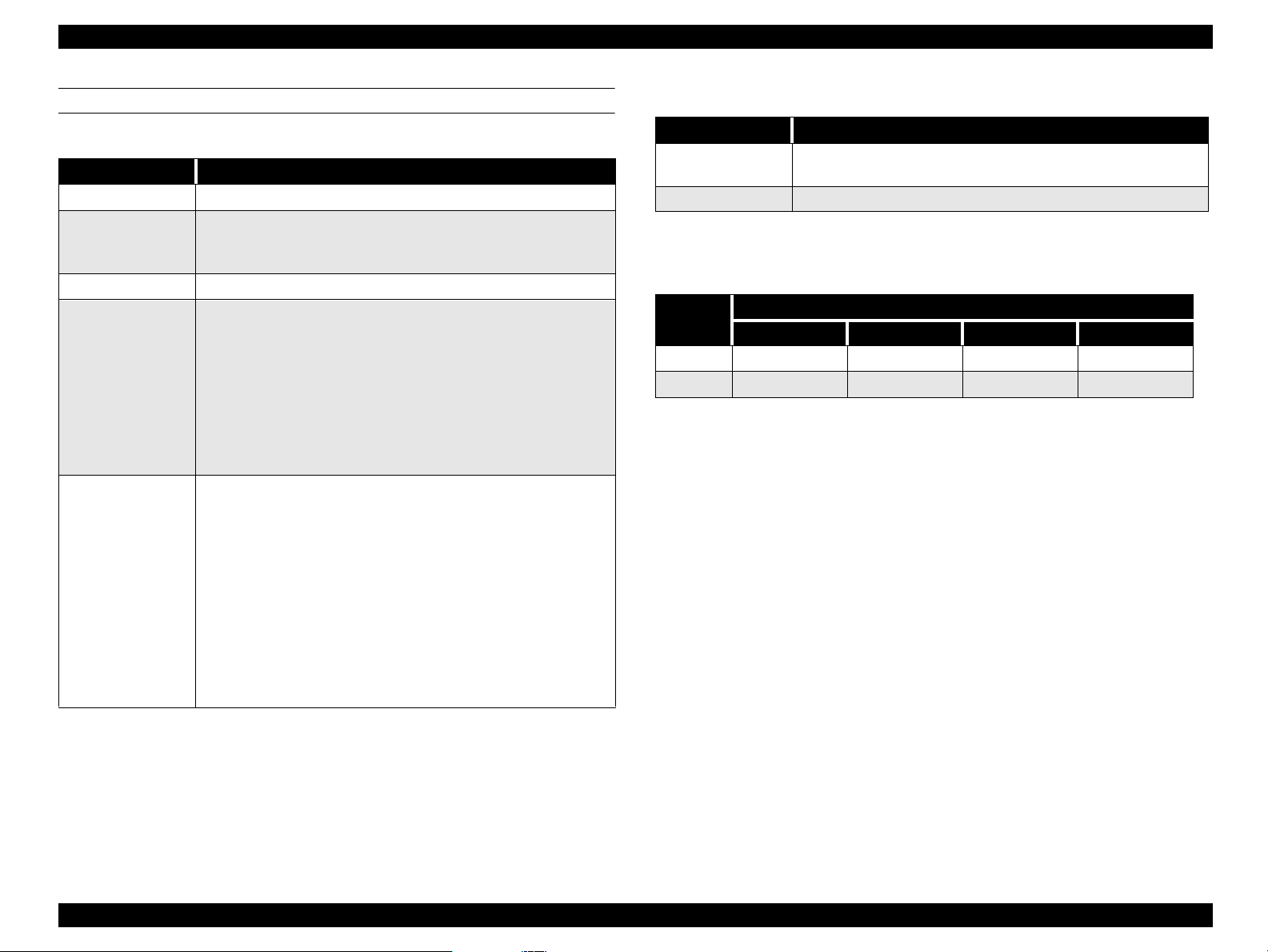
Revision Status
Revision Issued Date Description
Revision A October 4, 1999 Full version
Revision B October 20, 1999
Changed Disassembly and Troubleshooting to account for ASP blue
protective tape, also fixed scanner removal description
5
Page 6

EPSON Stylus Scan 2000 Revision A
Contents
Product Description
Features............................................................. ....... ...... ....... ...... .................. 9
General Specifications ............................................................................... 10
Local copy.............................................................................................. 10
Scan area................................................................................................ 10
Print area................................................................................................ 11
Printer..................................................................................................... 12
Scanner .................................................................................................. 15
Common................................................................................................. 16
Interfaces..................................................................................................... 17
Printer interface ..................................................................................... 17
Scanner interfaces................................................................................. 22
Control Panel............................................................................................... 23
Buttons................................................................................................... 23
Control panel indicates the printer’s condition................................... 25
Initialization............................................................................................ 26
Stylus Scan Errors ...................................................................................... 28
Physical Characteristics.............................................................................. 29
Dimensions............................................................................................ 29
Weight.................................................................................................... 29
External view ......................................................................................... 29
Operating Principles
General........................................................................................................ 31
Printer Mechanism Operation ................................................................... 32
Printing Mechanism.............................................................................. 33
Printing Process..................................................................................... 34
Carriage Mechanism ............................................................................. 35
Paper Feeding Mechanism ................................................................... 37
Ink System ............................................................................................. 42
Pump, Carriage Lock, Head Cleaner Mechanism................................ 43
Scanner Mechanism Operation................................................................. 46
Mechanism ............................................................................................ 46
Local and PC-Centric Copy Principles....................................................... 47
Local copy process................................................................................ 47
PC-Centric copy process....................................................................... 47
Electrical Circuit Operating Principles ...................................................... 49
B101 PSB/PSE Board............................................................................. 50
B101 MAIN Board.................................................................................. 53
Troubleshooting
Unit Level Troubleshooting....................................................................... 57
Printer/Scanner does not operate at power on................................... 58
Error is detected .................................................................................... 59
Failure occurs during printing.............................................................. 59
Printer does not feed paper correctly.................................................. 60
Control panel operation is abnormal................................................... 60
Repair of the Printer Mechanism .............................................................. 61
Troubleshooting the Scanner.................................................................... 65
Scanner Troubleshooting Flowcharts.................................................. 65
Scanner troubleshooting check points................................................ 66
Troubleshooting the Motors and Sensors ............................................... 69
6
Page 7

EPSON Stylus Scan 2000 Revision A
Disassembly & Assembly
Overview ..................................................................................................... 71
Precautions for Disassembling the Printer.......................................... 71
Tools....................................................................................................... 72
Screw Numbering System and Specifications ................................... 73
Service Checks After Repair ................................................................. 74
Disassembly Procedures............................................................................ 76
Removing the Housing ................................................... ...... ................ 77
Removal of printer consumables......................................................... 81
Removing the Circuit Board Tray............... ....... ...... ....... ...... ....... ...... ... 84
Removing the Scanner Mechanism..... ...... ....... ...... ....... ...... ................ 88
Disassembling the Printer Mechanism................................................ 94
Adjustment
Required Adjustments.............................................................................. 108
Adjustment Tools Required................................................................ 110
Printer Adjustment ................................................................................... 110
Printer hardware adjustments............................................................ 111
Using the Service-Adjustment Program................................................. 113
Installing the program......................................................................... 113
Opening the Start-up menu................................................................ 114
Initial Ink Charge Operation................................................................ 119
Bi-D Adjustment .... ...... ...... ....... ....................................... ...... ....... ...... . 120
Head Cleaning Operation.................................................................... 121
Head Voltage ID Input................................. ....... ...... ....... ...... ....... ...... . 122
Head Angular Adjustment .................................................................. 123
Ink draining..................................... ....................................... ....... ...... . 125
Scanner Adjustment................................................................................. 125
Maintenance
Printer-Related Maintenance................................................................... 127
Cleaning .................................................................................................... 128
Exterior................................................................................................. 128
Inside.................................................................................................... 128
Lubrication ................................................................................................ 129
Printer Mechanism .............................................................................. 129
Appendix
Connector Summary................................................................................ 138
Board Connector Summary................................................................ 139
Connector Pin Assignment................................................................. 140
EEPROM Address Map............................................................................. 143
Exploded Diagrams.................................................................................. 148
Parts List.................................................................................................... 155
Component Layout................................................................................... 160
Circuit Diagrams.................................... ...... ....... ...... ....... ...... ....... ...... ...... 165
7
Page 8

PRODUCT DESCRIPTION
CHAPTER
1
Page 9
EPSON Stylus Scan 2000 Revision A
1.1 Features
The major features of the EPSON Stylus Scan 2000 are:
High Color Print Quality
1440 (H) X 720 (V) dpi printing
Four Color Printing (CMYK)
Traditional and New Microweave
Sheet-fed 300dpi scanning
High quality local copy
One color copy mode Text & Graphics
Two B&W copy modes Black & White, Grayscale
High speed local copy
Color normal mode copy Max. 1.2 PPM
Gray mode copy Max. 1.3 PPM
B/W normal mode copy Max. 3.0 PPM
Two Built-in Interfaces
Bi-directional parallel I/F (IEEE-1284 level 1 device)
USB
Windows/Macintosh exclusive
Copy settings from the computer
Auto Photo Fine
Auto Enlarge
Auto Layout
Background reduction
Installed functions are the same or equivalent to the EPSON Stylus
Color 740 and the GT-2200.
Small footprint 228 x 437 x 279 mm (HWD)
Local copy settings from the control panel
Enlargement 141%
Reduction 93%, 70%
Copy size protection Letter/Half Letter/5 x 8”/Legal
A4/B5/A6
(Copy size protection prevents the printhead from firing ink onto the platen
in cases where the loaded paper size does not match the paper size
selected in the software.)
Built-in Auto Sheet Feeder
Holds 100 cut-sheets (64g/m2)
Holds 10 envelopes
Holds 30 transparency films
Product Description Features 9
Page 10
EPSON Stylus Scan 2000 Revision A
1.2 General Specifications
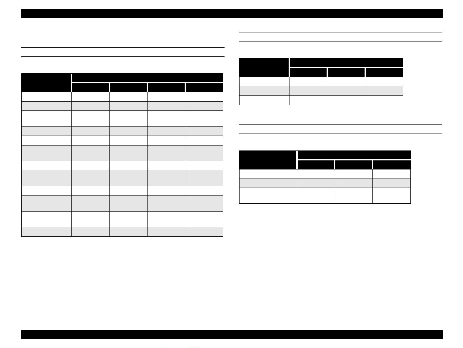
1.2.1 Local copy
1. Local copy
Table 1-1. Local Copy Specifications
Mode
B/W 300x300 Line art 360x360 Off No Bi-D Normal
B/W
Grayscale 300x300 Gray 360x360 On No Bi-D Normal
Text &
Color
Graphics
Output mode = data from the scanner ASIC to the printer
Scan
res.
300x300
2. Enlargement: Default 100%
Enlargement 141%
Reduction 70%, 93%
(not continuous)
3. Copy size Max. copy size 216 x 355.6mm (8.5 x 14inches)
Copy size protection A4/B5/A6 (A-size version)
Output
mode
Full
color
Print
res.
360x360 On No Bi-D Normal
Micro
Weave
Variable
dot
Head
seq.
Media
(Top, bottom, and both sides
need 3mm margins)
Letter/Half Letter/5 x 8”/Legal
(Letter size version)
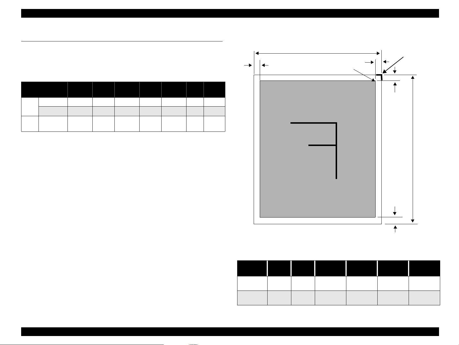
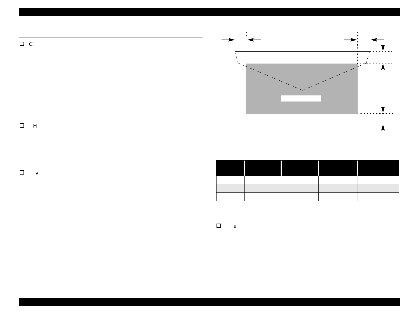
1.2.2 Scan area
LM
PW
Starting scan
position (1st bit)
Scanning Area
RM
TM
Document
edge (scale
edge)
PL
BM
4. Printing paper size Normal paper A4/Letter
Photo paper A4/Letter
Figure 1-1. Scan Area
Table 1-2. Scan Area
Document
size
A4 210mm 297mm
Letter 216mm
PW
(width)PL(length)
355.6mmat least
LM
(left)
at least
3mm
3mm
RM
(right)
at least
3mm
at least
3mm
TM
(top)
at least
3mm
at least
3mm
BM
(bottom)
at least
3mm
at least
3mm
Product Description General Specifications 10
Page 11
EPSON Stylus Scan 2000 Revision A
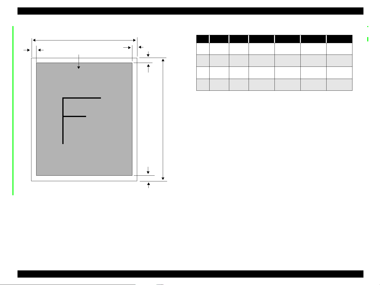
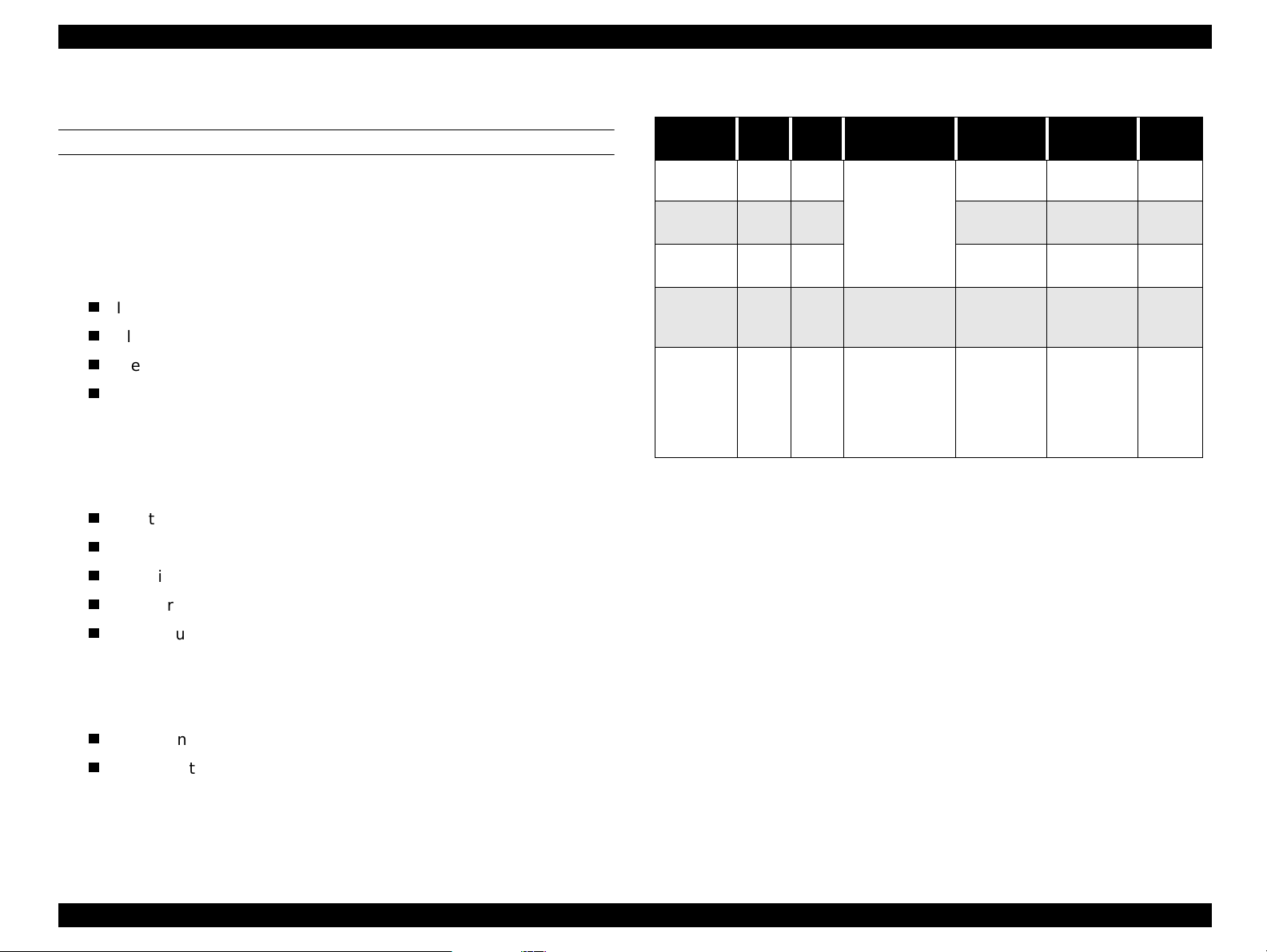
1.2.3 Print area
LM
PW
Paper feed direction
Printable Area
RM
TM
BM
PL
Table 1-3. Print Area
Size PW PL LM RM TM BM
A4 210mm 297mm
Letter 216mm 279mm
B5 182mm 257mm
Legal 216mm 356mm
at least
3mm
at least
3mm
at least
3mm
at least
3mm
at least
3mm
at least
3mm
at least
3mm
at least
3mm
at least
3mm
at least
3mm
at least
3mm
at least
3mm
at least
3mm
at least
3mm
at least
3mm
at least
3mm
Figure 1-2. Print Area
Product Description General Specifications 11
Page 12

EPSON Stylus Scan 2000 Revision A
1.2.4 Printer
PRINTING
Print method Drop On Demand ink jet
Nozzle configuration monochrome 144 nozzles (48 x 3 staggered)
color 48 nozzles each (cyan, magenta, yellow)
Print direction Bi-direction with logic seeking
Print speed & printable columns
Table 1-4. Character mode
Character pitch Printable columns LQ speed
10 CPI (Pica) 80 200 cps
Table 1-5. Raster graphic mode
Horizontal
resolution
180 dpi 8.26 inch 1488 20 IPS
360 dpi 8.26 inch 2976 20 IPS
720 dpi 8.26 inch 5952 20 IPS
Printable area Available dots CR speed
PAPER FEED
1. Feeding method Friction feed with ASF
2. Line spacing 1/6 inch or programmable at 1/360 inch
3. Paper path cut-sheet ASF (front enter, front out)
4. Feed speed 2.36 inch/sec. normal/ continuous
4.5 inch/sec. fast/continuous
CONTROL CODES
ESC/P Raster
EPSON Remote Command
Product Description General Specifications 12
Page 13
EPSON Stylus Scan 2000 Revision A
PAPER
Cut-sheets
size: A4 210(W) x 297mm (L) (8.3 x 11.7”)
Letter 216 x 279mm (8.5 x 11.0”)
B5 182 x 257mm (7.2 x 10.1”)
Legal 216 x 356mm (8.5 x 14.0”)
Statement 139.7 x 215.9mm (5.5 x 8.5”)
Executive 184.2 x 266.7mm (7.25 x 10.5”)
Photo paper 101.6 x 152.4mm (4 x 6”)
thickness: 0.08~0.11mm (0.003~0.004”)
weight: 64g/m
quality: Exclusive paper, bond paper, PPC
OHP sheets, Glossy paper
size: A4 210(W) x 297mm (L) (8.3 x 11.7”)
thickness: 0.075~0.085mm (0.003~0.0033”)
NOTE: Transparency printing is only supported at normal temperature.
Envelopes
size: No.10 241(W) x 104.8mm (H) (9.5 x 4.125”)
thickness: 0.16~0.52mm (0.006~0.02”)
weight: 45g/m
quality: Exclusive paper, bond paper, Air mail
2
~90g/m2 (17~24lb.)
Letter 216 x 279mm (8.5 x 11.0”)
DL 220 x 110mm (8.7 x 4.3”)
C6 162 x 114mm (6.4 x 4.5”)
2
~75g/m2 (12~20lb.)
LM
Printable Area
Figure 1-3. Printable Area for Envelopes
Table 1-6. Envelope Margin
Size
#10 3 mm (0.12”) 28 mm (1.10”) 3 mm (0.12”) 14 mm (0.55”)
DL 3 mm (0.12”) 7 mm (0.28”) 3 mm (0.12”) 14 mm (0.55”)
C6 3 mm (0.12”) 3 mm (0.12”) 3 mm (0.12”) 14 mm (0.55”)
Left Margin
(min.)
NOTE: Envelope printing is only supported at normal temperature.
Load long edge first.
Index cards
size: A6 index 105(W) x 148mm (L) (4.1 x 5.8”)
thickness: less than 0.23mm (0.0091”)
Right Margin
(min.)
Top Margin
(min.)
Bottom Margin
A5 index 148 x 210mm (5.8 x 8.3”)
5x8” index 127 x 203mm (5.0 x 8.0”)
10x8” index 254 x 203mm (10.0 x 8.0”)
(min.)
RM
TM
BM
Product Description General Specifications 13
Page 14
EPSON Stylus Scan 2000 Revision A
42.9
38.5
52.7
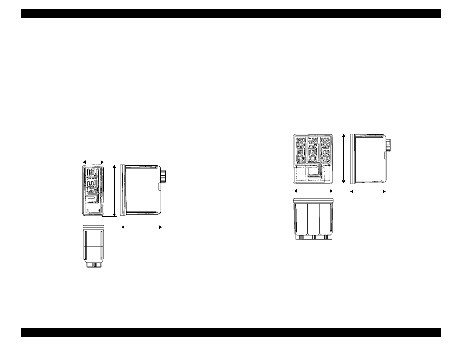
INK
1. Ink cartridge (black)
Type: Exclusive cartridge
Color: Black
Print capacity: 900 p ages/A4 (ISO/IEC 10561 Letter pattern
360dpi)
Ink life: Two years from production date
Storage temperature: -20~40°C (storage, less than a month at 40°C)
-30~40°C (packing storage, less than month at
40°C)
-30~60°C (transit, within 120 hours at 60°C and
within a month at 40°C)
Dimensions: 27.8 (W) x 52.7 (D) x 38.5mm (H)
27.8
52.7
2. Ink cartridge (color)
Type: Exclusive cartridge
Colors: Magenta, cyan, and yellow
Print capacity: 300 pages/A4 (360 dpi, 5% duty each color)
Ink life: Two years from production date
Storage temperature: -20~40°C (storage, less than a month at 40°C)
-30~40°C (packing storage, less than month at
40°C)
-30~60°C (transit, within 120 hours at 60°C and
within a month at 40°C)
Dimensions: 42.9 (W) x 52.7 (D) x 38.5mm (H)
38.5
Figure 1-5. Color Ink Cartridge
NOTE: Ink cartridges are consumable products and cannot by any
means be refilled.
Do not use cartridges that have passed their expiration date.
Figure 1-4. Black Ink Cartridge
Ink will freeze at less than -4°C but can be used after thawing
for three hours at room temperature.
Product Description General Specifications 14
Page 15

EPSON Stylus Scan 2000 Revision A
INPUT DATA BUFFER
64K bytes
1.2.5 Scanner
Product type Sheet-fed color image scanner (without ADF)
Sub scan method Sheet-fed type
Photoelectric d e vice Color CCD line sensor
Max. scan area 8.5 x 14” (216 x 355.6mm)
Max. effective pixels 2550 x 4220 pixels (300dpi)
Scan resolution main = 300dpi and sub = 300dpi
Output resolution 50~4800 dpi (1dpi increments)
Scan speed (300dpi, Draft mode)
Color = 4.25 msec/line
Monochrome (bi-level) = 1.68 msec/line
Color separation By the CCD color filter
Command level ESC/I - B7
Zoom 50~200% (1% increments)
Pixel depth 8 bits/color (input 12 bits/pixel/color,
output 8 bits/pixel/color)
Gamma correction CRT two levels (A,B)
PRINTER three levels (A,B,C)
User defined = one level
Color correction Impact-dot printer
Thermal printer
Ink-jet printer
CRT display
User defined
Brightness Seven levels
Line art Fixed threshold
TET
Digital halftoning AAS
Error diffusion three modes (A,B,C)
(Bi-level, Quad-level) Dither (resident) four modes (A,B,C,D)
Dither (user defined) two modes (A,B)
Interface USB and IEEE1284.4
Light source White cold cathode fluorescent lamp
Product Description General Specifications 15
Page 16

EPSON Stylus Scan 2000 Revision A
1.2.6 Common
ELECTRICAL SPECIFICATIONS
Rated voltage AC 120V
AC 220~240V
Input voltage AC 99~132V
AC 198~264V
Rated current 0.6A (AC 120V model)
0.4A (AC 220-240V model)
Rated frequency range 50~60 Hz
Input frequency range 49.5~60.5 Hz
Power consumption Approx. 29W (local copy printing)
Insulation resistance 10M
SAFETY, EMC
Safety UL1950 (UL)
EMC FCC Part15 Subpart B Class B
Ω
at 500V DC
(between AC line and chassis)
CSA C22.2 No. 950 (CSA)
EN60950 (VDE)
CSA C108.8 Class B
AS/NZS3548 Class B
ENVIRONMENTAL CONDITIONS
Temperature 10~35°C (operating, see figure below)
-20~60°C (non-operating, in packaging)
One month at 40°C
120 hours at 60°C
Humidity 20~80% RH (operating, without condensation, see
figure below)
5~85% RH (non-operating, in packaging without
condensation)
90
80
70
60
Humidity (%)
50
40
30
20
10
10
20
27 30 35
40
Temperature (°C)
Figure 1-6. Environment
CE Marking
Low voltage directive 73/23/EEC EN60950
Resistance to shock 1 G, within one ms (operating)
2 G, within two ms (non-op e rating, in packaging)
EMC Directive 89/336/EEC EN55022 Class B
EN61000-3-2
EN61000-3-3
Resistance to vibration0.15G (operating)
0.50G (non-operating, in packaging)
EN50082-1
IEC 801-2/801-3/801-4
RELIABILITY
Main unit Life 75,000 pages
Lamp Life 15,000 hours
Product Description General Specifications 16
Page 17
EPSON Stylus Scan 2000 Revision A
1.3 Interfaces
This section is divided into printer and scanner interface specifications. See the
following section for printer interface details or see “Scanner interfaces” on
page 22 for scanner interface details.
1.3.1 Printer interface
PARALLEL
BUSY signal is set high before setting either -ERROR low or PE high, and held
high until all these signals return to their inactive state.
BUSY signal is at high level in the following cases:
During data entry (see data transmission timing)
When input data buffer is full
During -INIT signal is at low level or during hardware initialization
During printer error (see -ERROR signal)
When the parallel interface is not selected
ERROR signal is at low level when the printer is in one of the following states:
Printer hardware error (fatal error)
Paper-out error
Paper-jam error
Ink-out error
PE signal is at high level during paper-out error.
1. Specifications
Transmission mode 8 bit parallel, IEEE-1284 ECP compatibility/nibble
mode
Synchronization Refer to the IEEE-1284 specification
Handshaking Refer to the IEEE-1284 specification
Packet Refer to the IEEE-P1284.4 Standard for Data Delivery
and Logical Channels for IEEE Std. 1284 Interface
(Draft D1.50)
Signal level TTL compatible level (IEEE-1284 Level 1 device)
Data trans. timing Refer to the IEEE-1284 specification
2. Connector pin assignment and signals
Table 1-7. Forward channel pin assignments and signals
Pin # Signal Name
1 -STROBE 19 In
2 DATA0 20 In
3 DATA1 21 In
4 DATA2 22 In
5 DATA3 23 In
6 DATA4 24 In
7 DATA5 25 In
8 DATA6 26 In
9 DATA7 27 In
10 -ACKNLG 28 Out
11 BUSY 29 Out
12 PE 28 Out
13 SLCT 28 Out
14 -AFXT 30 In Not used
31 -INIT 30 In
Return
GND pin
In/Out Description
The strobe pulse. Read-in data is
preformed at the falling edge of this
pulse.
The DATA0 through DATA7 signals
represent data bits 0 to 7, respectively.
Each signal is high when data is logical
1 and low when data is logical 0.
A negative signal that indicates the
printer is ready to accept data
A high signal that indicates the printer
is not ready and cannot receive data
A high signal indicates a paper-out
error
Always at high level when the printer
is on
The falling edge of a negative pulse or
a low signal on this line causes the
printer to initialize. Minimum 50us
pulse necessary.
Product Description Interfaces 17
Page 18
EPSON Stylus Scan 2000 Revision A
Table 1-7. Forward channel pin assignments and signals
Pin # Signal Name
32 -ERROR 29 Out
36 -SLIN 30 In Not used
18 Logic H - Out Pulled up to +5V via 3.9KΩ resistor
35 +5V - Out Pulled up to +5V via 3.3KΩ resistor
17 Chassis GND - - Chassis GND
16, 33
19-30
15,34 NC - - Not connected.
GND - - Signal GND
Return
GND pin
In/Out Description
A low signal indicates a printer error
condition
Table 1-8. Reverse channel pin assignments and signals
Pin # Signal Name
1 HostClk 19 In
2 DATA0 20 In
3 DATA1 21 In
4 DATA2 22 In
5 DATA3 23 In
6 DATA4 24 In
7 DATA5 25 In
8 DATA6 26 In
9 DATA7 27 In
10 PeriphClk 28 Out
11 PeriphAck 29 Out
12 nAckReverse 28 Out
Return
GND pin
In/Out Description
Data or address information
transferred from host to product.
The DATA0 through DATA7 signals
represent data bits 0 to 7,
respectively. Each signal is high
when data is logical 1 and low when
data is logical 0.
These signals are use d to trans fer the
1284 extensibility request values to
the printer.
Data transferred from product to
host.
Printer busy signal and reverse
channel transfer data bit 3 or 7
Printer goes to Low and approves
nReverseRequest
Table 1-8. Reverse channel pin assignments and signals
Pin # Signal Name
13 Xflag 28 Out
14 HostAck 30 In
nReverseReque
31
st
32 nPeriphRequest 29 Out This signal produces a host interrupt.
36 1284-Active 30 In 1284 active signal, High in ECP mode.
18 Periph-Logic H - Out
35 +5V - Out
17 Chassis GND - - Chassis GND
16, 33
19-30
15,34 NC - - Not connected.
GND - - Signal GND
3. Data trans. timing Refer to the IEEE-1284 specification and the
following.
Return
GND pin
30 In
In/Out Description
X-flag signal and reverse channel
transfer data bit 1 or 5
Host uses this signal for flow control
in reverse direction. Also this signal
offers the data bit 9 that is used to
judge whether the data or command
will be sent on the data signal in
forward direction.
This signal goes low to cha nge to the
reverse channel.
Always high. Pulled up to +5V via
3.9KΩ resistor
Always high. Pulled up to +5V via
1.0KΩ resistor
Product Description Interfaces 18
Page 19
EPSON Stylus Scan 2000 Revision A
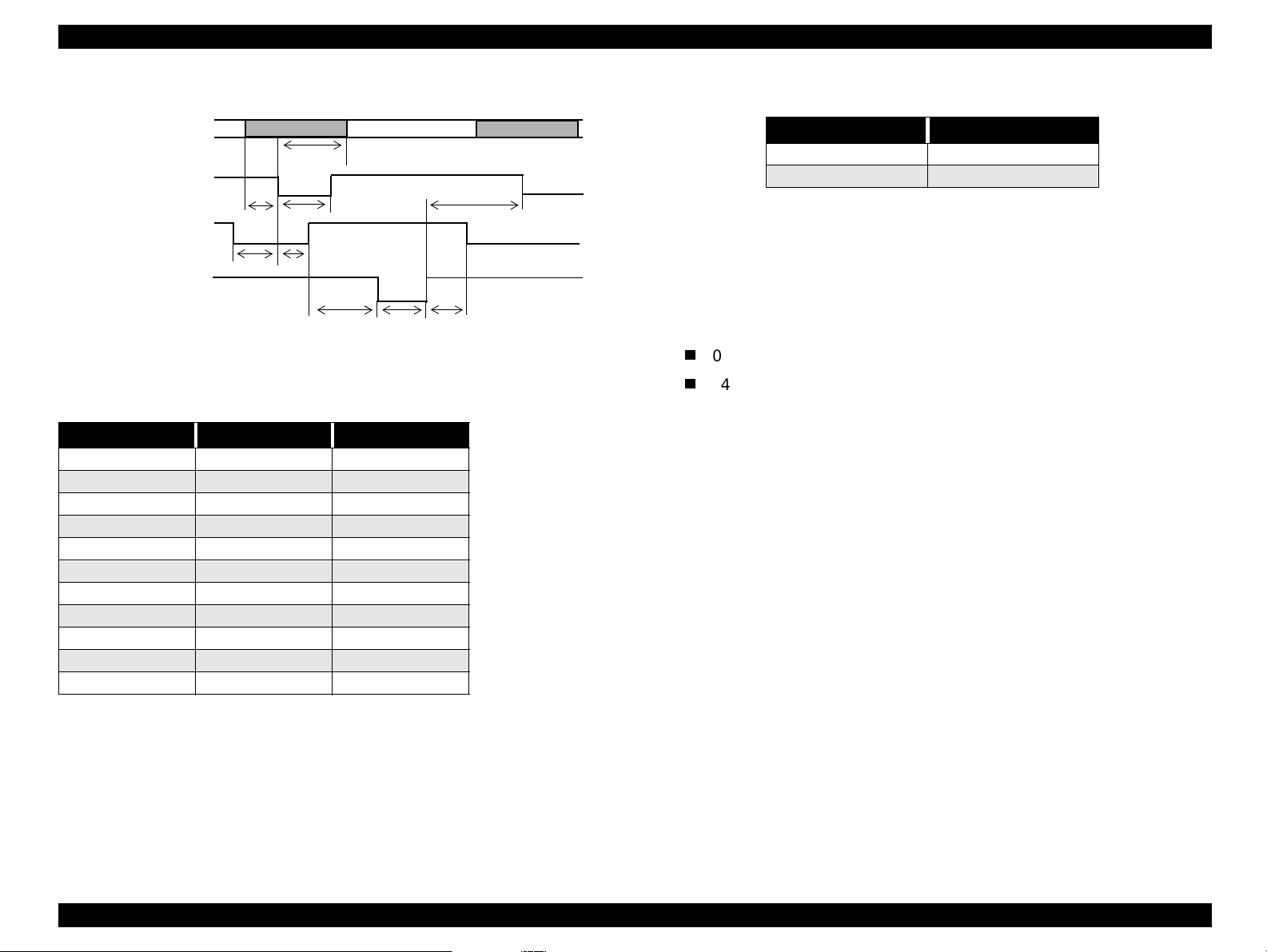
Table 1-10. Typical tack time
DATA
-STROBE
BUSY
-ACKNLG
ready
t
setup
t
data byte n
hold
t
t
busy
stb
t
data byte n +
next
t
Parallel I/F mode Time required
High speed 1 us
Normal speed 3 us
* The Logic H signal goes low, 2.0 V or less, when the printer is turned off and
goes high, 3.0 V or more, when the printer is turned on. The receiver shall
provide an impedance equivalent to 7.5 KΩ to ground.
4. Extensibility Request:
reply
t
Figure 1-7. Data Transmission Timing
Table 1-9. Data transmission times
Parameter Minimum Maximum
tsetup 500 ns -
thold 500 ns -
tstb 500 ns -
tready 0 -
tbusy - 500 ns
tt-out* - 120 ns
tt-in** - 200 ns
treply 0 -
tack 500 ns 10 us
tnbusy 0 -
tnext 0 -
* Rise and fall time of every output signal
** Rise and fall time of every input signal
ack
t
nbusy
t
The printer responds affirmatively when the extensibility request values are
00H or 04H, which mean
00H Request nibble mode reverse channel transfer
04H Request Device ID;
Return data using nibble mode reverse channel transfer
Device ID:
The printer sends the following device ID string when it is requested.
IEEE 1284.4 is enabled,
[00H][5EH]
MFG:EPSON;
CMD:ESCPL2,BDC,D4,SPC;
MDL:Stylus[SP]Scan[SP]2000;
CLS:PRINTER
DES:EPSON[SP]Stylus[SP]Scan[SP]2000;
Note: (1)[00H] denotes a hexadecimal value of zero
(2)MDL value depends on the EEPROM setting.
Product Description Interfaces 19
Page 20
EPSON Stylus Scan 2000 Revision A
USB
Standard :based on
“Universal Serial Bus Specifications Revision 1.0”
“Universal Serial Bus Device Class Definition for
Printing Devices Version 1.0”
Bit rate :12Mbps (Full speed device)
Data encoding :NRZI
Adaptable connector :USB series B
Suggested cable length :2 meters
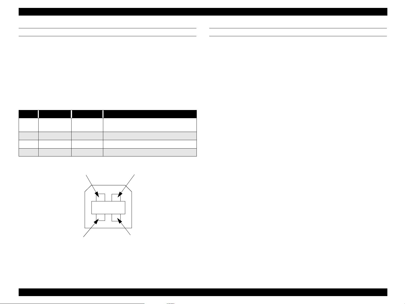
Table 1-11. USB connector pin assignments and signals
Pin no. Signal name In/Out Description
1 VCC 2 -Data bi-directional data
3 +Data bi-directional data, pull up to +3.3V via 1.5K Ω resistor
4 Ground - Cable ground
Pin #2
Cable power, max. power consumption is
100mA
Pin #1
PREVENTING DATA TRANSFER TIME-OUTS
Generally, hosts abandon data transfer to peripherals when a perip heral is in
the busy state for dozens of seconds continuously. To prevent hosts from
entering this kind of time-out period, the printer slows down the data reception
rate to around several bytes per minute, even if the printer is in the busy state.
This slowdown starts when the remaining open buffer area decreases to
several hundred bytes. The Stylus Scan enters a continuous busy state if the
input buffer becomes full.
Pin #3
Pin #4
Figure 1-8. USB Pins
Product Description Interfaces 20
Page 21
EPSON Stylus Scan 2000 Revision A
INTERFACE SELECTION
The Stylus Scan has two built-in interfaces; the USB and parallel interfaces.
The interface in use is selected automatically.
Automatic selection
When the Stylus Scan is turned on, it initializes and then goes into an idle
state. During this idle period the printer scans the interfaces for incoming
data. The interface that receives data first is selected.
When the host stops transferring data and the printer is in the stand-by
state for a certain amount of time, the printer returns to the idle state. As
long as the host sends data or the printer interface is in the busy state, the
interface selection does not change.
Interface status and selection
When the parallel interface is not selected, the interface goes into the busy
state. When the printer initializes or returns to th e idle state, the parallel
interface goes into the ready state. Be aware that an interrupt signal such
as the -INIT signal only takes effect on the parallel in ter face when the
parallel interface is selected.
IEEE1284.4 PROTOCOL
The packet protocol described by IEEE1284.4 standard allows a device to
carry on multiple exchanges or conversations which contain data and/or
control information with another device at the same time across a single pointto-point link. The protocol is not, however, a device control language. It does
provide basic transport-level flow control and multiplexing services. The
multiplexed logical channels are independent of each other and blocking of one
has no effect on the others. The protocol operates over IEEE1284.
Automatic Selection
An initial state is compatible interface and starts IEEE1284.4
communication when magic strings (1284.4 synchronous commands)
are received.
On
An initial state is IEEE1284.4 communication and data that received it
by the time it is able to take synchronization by magic string (1284.4
synchronous commands) is discarded.
Off
An initial state is compatible interface and never starts IEEE1284.4
communication even if magic strings (1284.4 synchronous commands)
are received.
Product Description Interfaces 21
Page 22

EPSON Stylus Scan 2000 Revision A
1.3.2 Scanner interfaces
PARALLEL
1. Specification
Transmission mode 8 bit parallel, IEEE-1284 ECP (Compatibility/Nibble)
mode
Synchronization Refer to the IEEE-1284 specification
Handshaking Refer to the IEEE-1284 specification
Packet Refer to the IEEE P1284.4 Standard for Data Delivery
and Logical Channels for IEEE Std. 1284 Interface
(Draft D1.50)
Refer to the IEEE 1284.4 specification
Signal level TTL compatible level (IEEE-1284 Level 1 device)
Data trans. timing Refer to the IEEE-1284 specification
2. Connector pin assignments
Refer to the IEEE-1284 specification
USB
Any items not included in this spec ificati on shall be in compliance with the
Universal Serial Bus Specification Revision 1.0
Configuration - the scanner supports the following configurations
Table 1-12. USB Configuration
Element Description
Full Speed Mode (12Mbit/s)
Class: Vendor-specific
Subclass: Vendor-specific
Device
Configuration
Interface
Endpoint
String Descriptor
Protocol: Vendor-specific
Vendor ID: 0x04B8 (Seiko Epson Corp.)
Product ID: 0x0105
Number of possible configurations: 1
Number of interfaces supported by this configuration: 1
Characteristics: Self-powered (Re mote wake-up feature not
supported)
Max. power consumption from VBUS: 2mA (5V)
No alternate setting
Number of endpoints used by this interface (excluding
endpoint 0):2
Class: Vendor specific
Subclass: Vendor specific
Protocol: Vendor specific
Bulk IN transfer
Max. data transfer size: 64 bytes
Bulk OUT transfer
Max. data transfer size: 64 bytes
Language ID: English, US
1: iManufacturer “EPSON”
2: iProduct “Scanner Stylus Scan 2000”
Requests
The scanner must support almost all standard device requests. The
scanner does not support vendor specific requests.
Some requests and descriptors depend on the configuration (endpoint
number) of each USB device. Therefore this specification recommends the
configuration where Endpoint 1 is Bulk IN endpoint and Endpoint 2 is OUT
endpoint.
Product Description Interfaces 22
Page 23
EPSON Stylus Scan 2000 Revision A
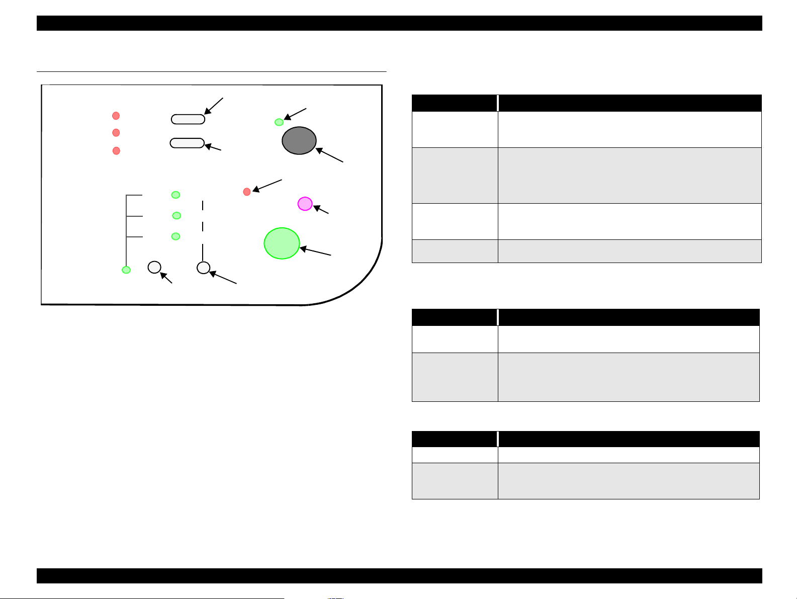
1.4 Control Panel
Paper Error
Black Ink
Maintenance
Color Ink
Maintenance
141
93%
70%
Enlarge/
Reduce
LED
Enlarge/Reduce
Selector
Figure 1-9. Control Panel
Paper Load/Eject
Ink
Maintenance
Scanner Error LED
Color
Bk Grayscale
Bk Text
Copy Mode
Selector
Operate LED
Power
button
Stop/Clear
button
Copy
button
1.4.1 Buttons
Table 1-13. Normal button functions
Button Function
• Loads or ejects paper
Load/Eject
Load/Eject
(pushed for two*
seconds)
Cleaning
(pushed for two*
seconds)
Cleaning
* The user’s guides state three seconds.
Button Function
Load/Eject
Load/Eject
+
Cleaning
• If the carriage is at the ink cartridge installation position,
returns the carriage back to the home position
• Starts the ink cartridge replacement sequence (not
available during printing). The carriage mo ves to the black
ink cartridge installation position first, and then to the
color ink cartridge installation position when pushed a
second time.
• Starts the printhead cleaning cycle.
• If the printer is in the “Ink Low” or “Ink Out” condition,
starts the ink cartridge replacement sequence.
• Returns the carriage from the ink cartridge replacement
position to the home position.
Table 1-14. Power-on button functions
Prints a status sheet that includes firmware version, ink
counter, and nozzle check patterns.
Enters the special-settings mode (see table below), which
remains active for three seconds. If neither the Load/Eject
nor Cleaning button is pushed in that three seconds, norma l
initialization begins.
Table 1-15. Special settings mode
Button Function
Load/Eject Resets the real-time counter (power-off time) in EEPROM
Cleaning
(hold for ten
seconds)
Resets the waste ink overflow counter
Product Description Control Panel 23
Page 24
EPSON Stylus Scan 2000 Revision A
COPY BUTTON
Table 1-16. Copy button functions
Button Function
Operate • Sets Local Copy Mode as the default.
• Stops the current copy job and ejects the paper during
Stop/Clear
Copy • The default setting for copying is
Copy Mode
Enlarge/Reduce
copying.
• Ejects paper during paper loading.
•Selects
• First press = LED shows current status
• Multiple presses (within 5 sec.s) = moves up one setting
each time
• Example
First time = Black Text LED activated (default)
Second time = Grayscale LED activated
Third time = Color Text & Graph LED activated
Fourth time = Black Text LED activated
• Selects reduce or enlarge
• Default = 100%
• First press = LED shows current status
• Multiple presses (within 5 sec.s) = moves up one setting
each time
• Example
First time = Enlarge/Reduce LED only (100%) activated
(default)
Second time = Enlarge/Reduce and 70% LEDs activated
Third time = Enlarge/Reduce and 93% LEDs activated
Fourth time = Enlarge/Reduce and 141% LEDs activated
Fifth time = Enlarge/Reduce LED only (100%) activated
Grayscale, Black Text,
B & W
Color (Text & Graphics)
or
and
100%
Table 1-17. Power-on functions for the Copy button
Button Function
Copy
Stop/Clear Changes printout paper size during copying (see below).
Prints a status sheet including firmware version and paper
size.
To change the printout paper size during copying, press the Stop/Clear button
until the appropriate indicator combination activates, as described below.
Table 1-18. Changing printout paper sizes during local copying
Paper size
Scanner Error Color Grayscale B lack Text
A4 on on off off
Letter on off off on
Control Panel Indicators
Product Description Control Panel 24
Page 25
EPSON Stylus Scan 2000 Revision A
1.4.2 Control panel indicates the printer’s condition
PRINTER
Table 1-19. Printer Condition
Printer status
Printing Flashing - - Ink charging Flashing - - Ink cartridge
replacement mode
Paper Out Flashing - - On
Paper jam - Off Off Flashing
No ink cartridge/
ink end black
Ink low black - Flashing - No ink cartridge/
ink end color
Ink low color - - Flashing Enter EEPROM and
Timer IC reset
Maintenance
request
Fatal error Flashing On On Flashing
Power Ink Out (BK) Ink Out (C) Paper Out
Flashing - - -
- On - -
- - On -
- On
Flashing Flashing On On
Indicators
On
(one second only)
SCANNER
Table 1-20. Scanner Condition
Scanner status
Power Error Priority
Lamp warming up Flashing - 1
Fatal error - On 1
Paper jam - On 2
“-” = does not matter
Indicators
LOCAL COPY
Table 1-21. Copy Status
Scanner status
Power on On - 3
Copying Fla sh ing - 2
Scanner/Printer error
Paper jam
“-” = does not matter
Power Error Priority
-On1
Indicators
“-” = does not matter
Product Description Control Panel 25
Page 26
EPSON Stylus Scan 2000 Revision A
1.4.3 Initialization
PRINTER
There are three initialization methods.
1. Power-on (hardware) initialization
The printer initializes when turned on or when it recognizes the cold-reset
command (remote RS command).
When the printer initializes, the following action s are p erformed.
Initialize printer mechanism
Clear input data buffer
Clear print buffer
Set default values
2. Operator initialization
The printer initializes when turn ed on, or when the p rinter recogn izes the -
INIT signal (negative pulse) from the parallel interface.
When the printer initializes, the following action s are p erformed.
Cap the printhead
Eject paper
Operation
Power on Valid Valid
Panel
Reset
Initialize by
command
STOP Valid -
CLEAR - Valid
Operat
StandbyController
ing
Valid Valid
Valid Valid
Table 1-22. Initialization
Scanner
process
Set the local
copy setting to
default
Stop copying
Setting remains
as is
• Setting
mode:
default
• Copy mode:
Multi-copies
volume 1
process
H/W
initialization
Controller
initialization
S/W
initialization
Cancel Eject paper
Printer
process
H/W
initialization
Panel
initialization
S/W
initialization
Restart
-
-
-
Copy
button
Clear input data buffer
Clear print buffer
Set default values
3. Software initialization
The ESC@ command also initializes the printer.
When the printer initializes, the following action s are p erformed.
Clear print buffer
Set default values
Product Description Control Panel 26
Page 27

EPSON Stylus Scan 2000 Revision A
SCANNER
There are three initialization methods.
1. Hardware initialization
The scanner initializes when turned on.
When the scanner initializes, the following actions are performed.
Initialize scanner mechanism
Clear input/output data buffer
Set default values
2. Operator initialization
The scanner initializes when it recognizes the -INIT signal (negative pulse)
from the parallel interface.
When the scanner initializes, the following actions are performed.
Clear input/output data buffer
Set default values
3. Software initialization
The ESC@ command also initializes the scanner.
When the scanner initializes, the following actions are performed.
Clear input/output data buffer
Set default values
Product Description Control Panel 27
Page 28

EPSON Stylus Scan 2000 Revision A
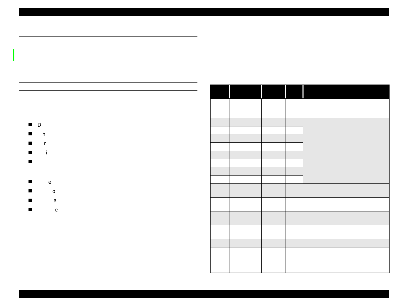
1.5 Stylus Scan Errors
PRINTER
Table 1-23. Printer Related Errors
Error Cause Solution
When one or more ink cartridges are
almost empty, the printer e nters the l ow-
Ink out
Paper out
Paper jam
No ink
cartridge
Maintenance
request
Fatal error
ink state and continues printing.
When the cartridge is complete ly empty ,
the printer indicates a n i nk-o ut e rro r an d
stops printing.
If the printer fails to properly load paper,
it indicates a paper-out error.
If the printer fails to properly eject paper,
it indicates a paper jam.
If the printer detects that one of the ink
cartridges is not installed, it indicates a
no-ink-cartridge error.
When the total amount of waste ink
reaches the limit, the printer indicates a
maintenance request and stops printing.
A carriage control or CG access error has
occurred.
Install a new ink
cartridge.
Load paper and press
the Load/Eject button.
Press the Load/Eject
button. If this does not
clear the error, remove
the paper by hand.
Install a new ink
cartridge.
Replace the waste ink
pads.
Turn off the Stylus
Scan and turn it back
on. If the error does not
clear, service.
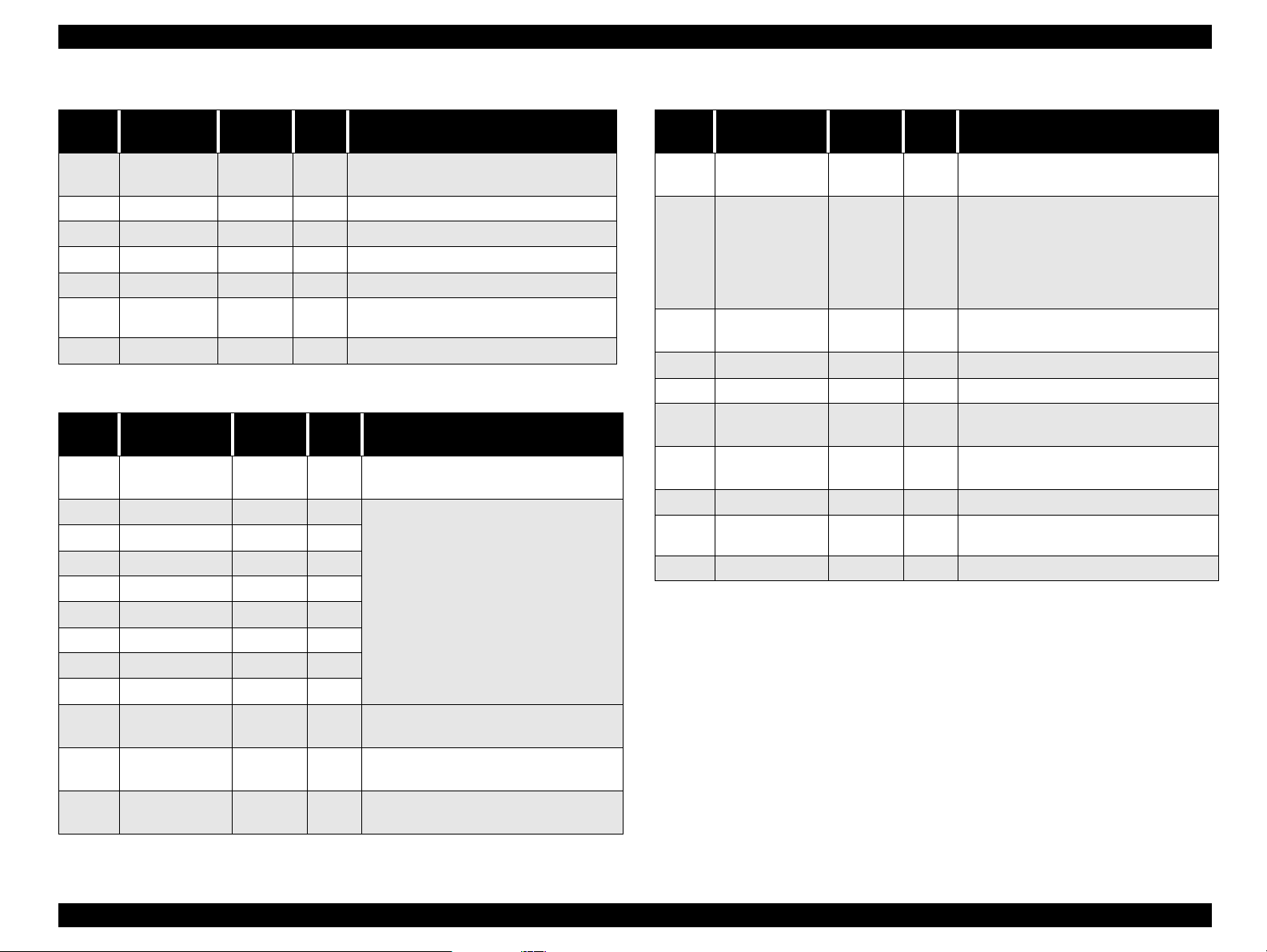
SCANNER
Table 1-24. Scanner Related Errors
Error Cause Solution
Fatal error
Command
error
• The lamp is broken.
• System breakdown.
• Scanner fails to eject the document.
• (Disposition)
Unidentified command detected.
(Disposition)
The scanner sent a NACK signal and is
waiting for the next command. If an
incorrect command or parameter is
received, it is disregarded and the
previous value is maintained.
Turn off the Stylus
Scan and turn it back
on. If the error does not
clear, service.
Turn off the lamp and
stop operation. Set bit 7
of the status byte.??
Send a correct
command to clear the
error.
NOTE: Do not re-install used ink cartridges. Doing so confuses the ink-
level detection function and may cause a serious problem in the
printhead.
Product Description Stylus Scan Errors 28
Page 29
EPSON Stylus Scan 2000 Revision A
1.6 Physical Characteristics
1.6.1 Dimensions
228 x 437 x 279 mm (HWD)
1.6.2 Weight
7.5 Kg
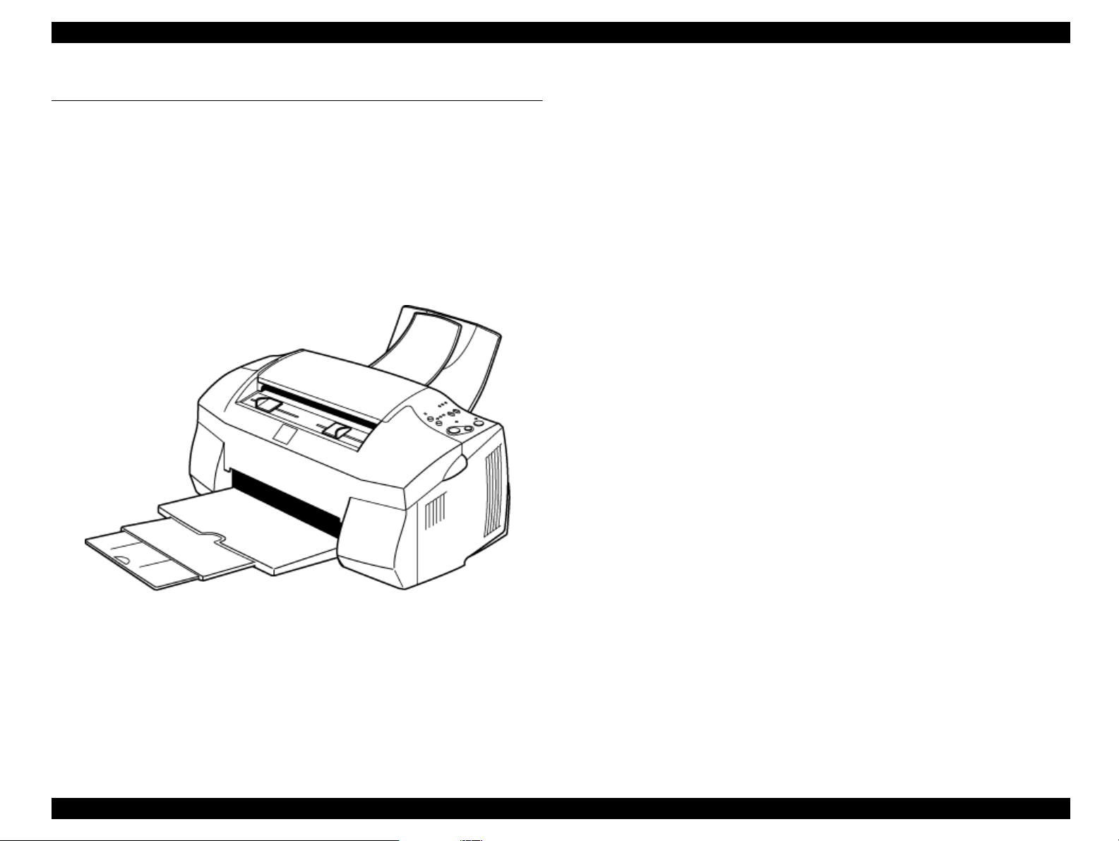
1.6.3 External view
Figure 1-10. EPSON Stylus Scan 2000
Product Description Physical Characteristics 29
Page 30

OPERATING PRINCIPLES
CHAPTER
2
Page 31

EPSON Stylus Scan 2000 Revision A
2.1 General
The main components of the EPSON Stylus Scan 2000 are the printer
mechanism, scanner mechanism, and the following electronic boards;
Main: B101 Main Board
Power Supply: B101 PSB/PSE Board
Panel: B101 PNL Board
Operating Principles General 31
Page 32

EPSON Stylus Scan 2000 Revision A
2.2 Printer Mechanism Operation
Like previous EPSON Ink Jet printers such as the Stylus Color 740, the printer
mechanism of the EPSON Stylus Scan 2000 does not have an exclusive
mechanism to switch from paper feeding to pumping and back. Instead, this
control is done by the rotational direction of the paper feed/pump motor and
also depends on the position of the carriage.
The printhead combines the b lack and CMY heads in one un it. The following
indicate the nozzle configurations of these 3 models.
Black Nozzles: 144 nozzles (120 dpi x 3 rows in staggered)
CMY Nozzles: 48 nozzles/colors (120 dpi x 1 row)
Table 2-1. Motor Types and Corresponding Functions
Motor Type Function
CR Motor Stepping Used to drive the carriage. page 35
• Drives the ASF to feed paper into
paper path
• Drives paper feed rollers at variable
PF Motor Stepping
speeds
• Drives the CR Lock lever (as
described on page 40)
• Drives pump unit to absorb ink
For details
see
page 37
PF motor
pinion
Intermittent
gear
PF Motor
Flushing section
Star wheel
Disengage flag
Black I/C sensor
CMY I/C sensor
Carriage unit
Printhead
(one unit)
Timing belt
Cap unit
Pump unit
Disengage
lever
73.6 Gear/Precision Gear
ASF
sensor
Detector
wheel
Loading
shaft
Loading
rollers
PE sensor
Carriage HP
sensor flag
Carriage HP
sensor
Figure 2-1 in the in the right column shows the outline of the printer
mechanism.
CR guide shaft
PF roller
CR Motor
PG lever
Figure 2-1. Printer Mechanism Block Diagram
Operating Principles Printer Mechanism Operation 32
Page 33

EPSON Stylus Scan 2000 Revision A
2.2.1 Printing Mechanism
The basic principles of the printhead are the same as previous models; DropOn-Demand type MACH head method.
You need to manually input the drive-voltage code (printed on top of the
printhead) for the multi-layer piezo electric element. Input this value every time
you replace the printhead, MAIN board, or printer mechanism.
The main parts of the printhead and carriage are described below.
PZT
PZT is an abbreviation of Piezo Electric Element . The print signal is sent
from the PSB/PSE board through the driver board on the
and to the PZT. Then, the appropriate PZT squeezes the cavity, forcing
the ink stored in the cavity out through the nozzle. This process is
described in more detail on the next page.
Ink cavity
Ink flows from the ink cartridge, through the filter, and to the ink cavity
where it is stored until one of the PZT units forces it out through the
nozzles.
Nozzle Plate
The bottom surface of the printhead which contains nozzle holes to
direct ejected ink toward the paper below. See the next page.
Filter
When the ink cartridge is installed, if any dirt or dust around the
cartridge needles is absorbed into the inside of the printhead, there is a
large possibility that the nozzles will clog. Clogged nozzles can be
detected by alignment failure and dot-missing problems. To prevent
these kinds of problems, a filter is set below the cartridge needle and
ink flows through the filter on its way to the ink cavity.
printhead
unit
Nozzle selector
Board
I/C Out
sensor
actuator
Needle
Ink cartridge
PZT
(Piezo)
unit
Nozzle
plate
Figure 2-2.
I/C Out sensor actuator
The I/C Out sensor detects whether or not an ink cartridge is installed
according to the position of the I/C Out sensor actuator. When a
cartridge is installed, the actuator is pushed down, which turns the
shaft that is connected to the act uator. The fl ag at the other end of t he
shaft activates the I/C Out sensor when the cartridge is fully in place.
Printhead
Ink cavity
Sectional Drawing
Filter
See the next page for more details on the nozzle s e lector board and the ink
ejecting process.
Operating Principles Printer Mechanism Operation 33
Page 34

EPSON Stylus Scan 2000 Revision A
Ejecting State:
2.2.2 Printing Process
The following figures show sectio nal drawing s of th e printh ead in the n ormal
and ejecting states.
Normal State:
1.
When no print signal is outpu t, the PZT is in the normal, standby, state.
2.
When a print signal is sent from the MAIN board, the IC (Nozzle Selector)
located on the printhead unit receives the data in 1-byte units. The Nozzle
Selector then sends the voltage signal on to the appropriate PZT. Due to
the physical properties of the PZT, electrical signals cause the PZT to
change shape. When the PZT changes shape, it squeezes the ink cavity,
ejecting ink out through the nozzles.
Ink course
Piezo unit
Nozzles
Figure 2-3. Printhead Normal State
Cavity
Nozzle plate
surface
Figure 2-4. Printhead Ejecting State
Operating Principles Printer Mechanism Operation 34
Page 35

EPSON Stylus Scan 2000 Revision A
Rotor
1
2
3
4
A
/A
B
/B
2.2.3 Carriage Mechanism
The carriage mechanism moves the carriage back and forth according to the
drive from the carriage motor. See Figure 2-6 on the next page.
The carriage motor is a 4-phase, 200-pole, stepping motor and is driven by 2-2
phase, 1-2 phase, Double 1-2 phase, 2-Double 1-2 phase, and 4-Double 1-2
phase drives. This stepping moto r allows the carriage to move freely to fixed
positions where necessary operations such as ink absorption can be
performed. The following tables show carriage the motor specifications and
motor controls.
Table 2-2. Carriage Motor Specifications
Items Description
Motor type 4-Phase/200-pole Stepping motor
Drive voltage Range 42VDC ± 5%
Internal coil resistance
Control method Bi-Polar Drive
Table 2-3. Phase drive
7.8 Ohms ± 10%(per phase under 25 °C
environment)
Table 2-4. CR Motor Control at Each Mode
Printing mode
High Speed Skip 340 4080
Normal Printing 200 2400
Capping 80 960
Wiping 40 480
Cap (Valve
Release)
Withdrawal of cap 5 60
Drive Speed
[CPS]
20 240
Drive frequency
[PPS]
Drive method
Double1-2, 2-2,1-2
phase drive*
Double 1-2, 2-2 phase
drive
2-Double 1-2, 2-2
phase drive
2-Double 1-2, 2-2
phase drive
4-Double 1-2, 2-2
phase drive
4-Double 1-2, 2-2
phase drive
Phase Drive inch/pulse mm/pulse
2-2 1/120 0.212
1-2 1/240 0.106
Double 1-2 1/480 0.053
2-Double 1-2 1/960 0.026
4-Double 1-2 1/1920 0.013
Figure 2-5. CR Motor Internal Circuit Diagram
Operating Principles Printer Mechanism Operation 35
Page 36

EPSON Stylus Scan 2000 Revision A
PLATEN GAP LEVER
Carriage
motor
Rear (thick
paper) position
Parallelism
adjust
lever
Paper feed
roller
Paper eject
rollers
Timing
belt
Paper guide
(front)
Home position
sensor
Carriage
unit
Forward
(normal)
position
Platen Gap
lever
Figure 2-6. Carriage Mechanism with platen gap lever (Top view)
As shown in Figure 2-6, the Platen Gap lever can be moved forward or back to
adjust for the thickness of the paper. The PG lever is connected to the carriage
guide shaft, which raises or lowers the carriage depending on the PG lever
position. The nozzle surface remains parallel to the paper in either position
thanks to a tilt adjustment mechanism. Also, the two parallelism-adjustment
levers, one mounted on each side of the carriage guide shaft, adjust the
parallelism between the platen and shaft when the shaft is installed in the
factory. This precise adjustm e nt is necessary to make sure the gap between
the platen surface and the printhead surface is 1.04 mm in the normal position
or 1.74 mm in the thick-paper position.
Operating Principles Printer Mechanism Operation 36
Page 37

EPSON Stylus Scan 2000 Revision A
Rotor
1
2
3
4
A
/A
B
/B
2.2.4 Paper Feeding Mechanism
The paper feeding process begins at the ASF, continues through the PF roller,
and ends at the paper eject roller (and star-wheel gear).
The ASF unit, which is common with the Stylus COLOR 740 printers, is driven
by the PF motor (stepping motor). Torque sent from this motor switches
between the ASF unit and pump/PF roller depending on the position of the
disengage lever (described later).
In the EPSON Stylus Scan 2000, a four-phase hybrid type pulse motor is used
in the PF motor as a motive power of the paper mechanism. The torque is sent
at 2-Double 1-2, Double 1-2, 1-2, and 2-2 phase drives. This motor drives the
paper-feeding mechanism as well as the pump mechanism which is necessary
for printhead cleaning. By using this pulse motor, it becomes possible to use
variable drive levels for many purposes, such as paper feed, slight paper feed,
and high or low speed absorption of pump operations. The following table
shows PF motor specifications.
Table 2-5. PF Motor Specifications
Item Description
Motor type 4-phase/200-pole Stepping motor
Drive voltage 42VDC ± 5%
Coil Resistance
8.8 Ohm ± 10%(per 1 phase under 25°C
environment)
Table 2-6. Phase drive
Phase Drive Inch/pulse mm/pulse
2-2 1/720 0.035
1-2 1/1440 0.018
Double 1-2 1/2880 0.0088
2-Double 1-2 1/5760 0.0044
Figure 2-7. PF Motor Internal Circuit Diagram
Control method Bi-Polar Drive
Phase drive 1-2, 2-2, Double 1-2, 2-Double 1-2
Operating Principles Printer Mechanism Operation 37
Page 38

EPSON Stylus Scan 2000 Revision A
Table 2-7. Print Modes and Drive Methods
Printing mode
High Speed Skip 340 4080
Normal Printing 200 2400
Capping 80 960
Wiping 40 480
Cap (Valve
Release)
Withdrawal of cap 5 60
Drive Speed
[CPS]
20 240
Drive frequency
[PPS]
Drive method
Double 1-2, 2-2,1-2
phase drive*
Double 1-2, 2-2 phase
drive
2-Double 1-2, 2-2
phase drive
2-Double1-2, 2-2 phase
drive
4-Double1-2, 2-2 phase
drive
4-Double 1-2, 2-2
phase drive
Drive from the PF motor is sent to the P F rollers and paper eject rollers as
described below.
To the PF rollers:
PF motor pinion gear (CCW rotation)
To the eject rollers:
PF motor pinion gear (CCW rotation)
(13.5, 30.8)
NOTE:
Above CCW rotation is mentioned viewing from the PF motor pinion
gear side.
→
Spur gear (28) → Paper eject rollers
→
Gear 73.6 → PF rollers
→
Gear 73.6 → Combination gear
Figure 2-8 shows a paper feeding mechanism block diagram, which includes
the parts along the PF motor drive-transmission paths.
Gear
73.6
Combination
Gear13.5,30.8
Paper Eject Roller
PF motor
Gear 28
PF Roller
Star Wheel Assy.
Figure 2-8. Paper Feeding Mechanism (Top View)
The printer feeds paper from the ASF (when the PE sensor located near the
carriage motor detects paper is loaded) through the paper path and stops
feeding when the paper’s leading edge reaches the halfway point of the front
paper guide. To correct for any misfeeding, the paper is fed back toward the
ASF a predetermined number of steps and then it is fed forward again until it
reaches the top-of-form position.
Once the printer starts printing, it advances paper using the PF rollers and
subrollers until it reaches the last 14mm of the paper, when it advances the
paper using the star wheel gear and paper eject rollers.
Torque sent from the ASF/Pump motor to the ASF unit via the disengage
mechanism is used for the following operation.
Operating Principles Printer Mechanism Operation 38
Page 39

EPSON Stylus Scan 2000 Revision A
MULTI-FEED PREVENTION MECHANISM
Like the Stylus COLOR 740 ASF, the ASF built in the Stylus Scan has the
multiple-paper-feeding-prevention mechanism to provide accurate and
consistent paper feeding. This mechanism prevents a sheet of paper from
falling from the paper set position in to the paper path. A paper return lever
in the mechanism pushes paper that may have fallen off back onto the
hopper. After this motion is completed, the LD roller starts loading paper .
The multiple-paper-feeding-prevention operation is described in the
following steps.
1. When the printer power is turned on, the ASF/Pump motor rotates
counterclockwise to detect ASF home position. Then the motor rotates
clockwise specified steps to set the LD roller and paper return lever to their
proper positions. (See “Standby State” in Figure 2-9.)
2. When the paper loading signal is sent from the PC or the Load/Eject button
is pressed, the PF motor turn s counterclockwise to let the LD roller load
paper. (See “Paper Pick Up State” in Figure 2-9.)
3. Due to the design of the ASF, the LD roller loses friction on the paper and
stops at the point where the paper is fed by the PF roller. (See “PF Roller
Paper Feed State” in Figure 2-9.)
4. When the next print signal is sent or the Load/Eject button is again
pressed, the PF motor rotates clockwise a specified number of steps to set
the LD roller and the paper return lever in place. (See “Standby State” in
Figure 2-9.)
NOTE: If no print signal is sent for a predetermined number of
seconds in step 4, the LD roller and the paper return lever
automatically return to the standby state.
Figure 2-9. Multiple Paper Loading Prevention Mechanism (right side view)
Operating Principles Printer Mechanism Operation 39
Page 40

EPSON Stylus Scan 2000 Revision A
SMALLER TRAILING-EDGE MARGIN
Like the Stylus COLOR 740, this model uses a new design to allow printing up
to the last 3mm by changing the design and position of the star-wheel gear.
The star-wheel gear assembly has been shifted 5 degrees from directly on top
of the eject rollers towards the front paper guide. This change suppresses the
tailing edge of the paper so that the old minimu m margin of 14mm has been
reduced to only 3mm.
Old Feeding
Method
Paper
New Feeding
Method (from
COLOR 740)
Star wheel
Assembly
Eject rollers
Moved to a 5
degree angle
Printhead Support roller
Platen
3mm bottom margin
may contact printhead
PF roller
CARRIAGE LOCK MECHANISM
The carriage lock mechanism prevents the carriage from being left at an
uncapped position for a long time which can occur due to user mistakes,
physical shock, vibration during transport, and so on. The CR lock mechanism
is driven by the stepping PF motor. See Table 2-5, “PF Motor Specifications,”
on page 37 for motor specifications.
The PF motor controls the CR lock mechanism as well as the PF mechanism
depending on the direction of the PF motor rotation. The CR lock mechanism is
located at the right end of the paper eject roller.
Top view
Bushing 6
Pump Planetary
Lever
CR Lock
Lever
Right-side view
Carriage
Paper Eject
roller
Middle frame
Pump
Planetary
Lever Guide
Figure 2-11. CR Lock Mechanism
While the PF motor drive is used for paper feeding (PF motor rotation = CCW),
This area remains
stable
the CR Lock Lever is set under the Paper Eject Frame. But the CR Lock lever
rises up and locks the carriage when the PF motor rotates CW.
Figure 2-10. 3mm improved margin (viewed from right side)
Operating Principles Printer Mechanism Operation 40
Page 41

EPSON Stylus Scan 2000 Revision A
The PF motor drive is sent to the CR Lock lever via the Paper Eject roller.
PF Motor pinion gear (CW rotation)
Gear 28
→
Paper Eject Roller
→
CR Lock Lever
→
Gear 73.6
→
Combination gear
→
If the carriage is left uncapped for a long time, ink on the printhead surface
gradually thickens and may clog the nozzles. In some cases, the nozzles may
be so thoroughly clogged that they cannot be cleared even after performing
multiple cleaning operation s.
To prevent clogged nozzles, the printer caps and locks the carriage in the
following conditions.
Power off sequence:
When power is turned off, even during printing, the printer caps and
locks the carriage at the end of the power-off sequence.
Power on sequence:
When power is turned on, the printer automatically performs an
automatic (power-on) cleaning cycle and then caps and locks the
carriage.
NOTE: The power-on cleaning cycle is an automatic head cleaning
sequence that is performed every time the power is turned on.
The timer IC, which is powered by the lithium battery,
measures the length of time the printer has been off. The
printer selects and performs the appropriate cleaning
operation according to the length of time it has been off.
PAPER PICK UP OPERATION
When the Load/Eject switch is pressed or printing order is inp ut, the carriage
unit moves until the left edge and collides with paper pick up trigger lever.
When the carriage collides with this trigger level, a planetary gear located on
the same axis is also pushed at the same time and conveys the motive power
on the platen to the adjoining gear line side for ASF drive.
Gear 34/
ASF roller
drive gear
Combination
gear 16,40.8
Paper pickup
trigger lever
Gear 36/
Eject roller
drive gear
Combination
G 12.4,28/
Eject roller
transmission
gear
PF motor
Spur 23.2/ASF
roller
transmission
gear
Gear 73.6
pinion gear
Combination G
16,21.6/Platen roller
transmission gear
Figure 2-12. Paper Pickup Mechanism
Paper eject sequence:
When the Load/Eject button is pressed, the printer ejects any paper in
the paper path. If no print data is received at this time, the printer caps
and locks the carriage and then enters the standby mode.
However, if no paper is in the paper path when the Load/Eject is
pressed, the printer loads a sheet and does not lock the carriage.
PF motor torque is always transmitted to the CR lock lever side, but the
operation of the CR lock mechanism varies depending on the rotation direction
of the motor.
Clockwise = sets the carriage lock lever
Counterclockwise= releases the carriage lock lever
Operating Principles Printer Mechanism Operation 41
Page 42

EPSON Stylus Scan 2000 Revision A
2.2.5 Ink System
Ink system mechanism consists of 1) cap mechanism, 2) pump mechanism, 3)
carriage lock mechanism, 4) waste ink absorber and 5) ink sequence. Out of
these mechanisms, 1) to 4) are physical mechanism and parts which are
mounted on the printer mechanism and 5) the ink sequence is performed
automatically by the firmware. The EPSON Stylus Scan 2000 has no engage/
disengage mechanism, meaning the pump and platen are always at work when
the PF motor operates. The figures below show printhead positions when the
ink system and various ink-pumping sequences are performed.
Eject roller
drive gear
PF roller drive
gear
Carriage lock
lever
Cleaner blade
A
B
Figure 2-14. Major Ink Sequence Positions on Carriage
Printable Area
2976 dots (360-dpi)
C
A. ASF Pick-up position
B. Flushing
C. Wiping/rubbing position
D. Flushing position
E. Ink Discharge position
F. Cap cleaning position
E
D
F
Eject roller
transmission
gear
PF (pump)
motor pinion
gear
Pump roller
Cap unit
Figure 2-13. Ink System Mechanism
Operating Principles Printer Mechanism Operation 42
Page 43

EPSON Stylus Scan 2000 Revision A
2.2.6 Pump, Carriage Lock, Head Cleaner Mechanism
n the EPSON Stylus Scan 2000, there is no switch or mechanism to switch
between the ink pump and paper feed operations. Therefore, whenever the
paper feed/pump motor rotates, the pump-drive roller inside the pump unit
rotates. However, the rotational direction of the rollers determines whether or
not the pump sucks ink. Also, even if the pump rotates in the ink-absorption
direction, ink is not abso rbed if the carriage is in the false-absorption position.
Figure 2-13 shows process of conveying motive power to the pump drive
roller.
The process of conveying the motive power to the paper eject roller is shown
in Figure 2-15. This motive power is conveyed to Gear C through Gear B. The
lever that drives Gear C, the carriage lock, and the head-cleaner mechanism is
shown separately but it is constructed as one unit. Since the engagement of
these parts depends on the tension of the compression spring, if the lever is
burdened, only Gear C and the pump roller rotate and no more motive power is
conveyed to the lever part.
Axis of
Paper
eject
roller
Gear C
Gear A
Gear B
Compression
spring
Pump drive
roller
Figure 2-15. Pump Mechanism Power Transmission Process
The table below shows PF/Pump motor rotational direction and pump system
operation.
Operating Principles Printer Mechanism Operation 43
Page 44

EPSON Stylus Scan 2000 Revision A
Table 2-8. Pump Motor Rotation and Operation
PF motor pinion gear rotation
(looking at gear surface)
Clockwise (CW)
forward rotation
Counterclockwise (CCW)
backward rotation
1) Release the tubes
2) Disengage Head Cleaner
3) Disengage carriage lock
1) Squeeze tubes to pump ink
2) Engage Head cleaner
3) Engage carriage lock
Refer to Figure 2-16 in the right column which shows the pump operations at
clockwise and counterclockwise rotation.
During ink-absorptive operations such as cleaning and flushing (but not during
normal printing), ink drains from the ink cartridge to the waste-ink pads
through the cap. During printing and flushing, ink is fired out of the nozzles by
the PZT. But during absorption operations the head is capped and ink is sucked
off the nozzle plate by the force of the vacuum created by the pump drive and
the PZT does not move.
Counter-Clockwise
Revolution
Pump unit operation
Clockwise
Revolution
Table 2-9. Pumping modes
Pump Mode Revolutions Absorption
Low speed 0.38rev/second 0.06m l/s ec ond
Regular
absorption
High speed 2.6rev/second 0.4ml/second
Super high speed 3.38rev/second 0.54ml/second
1.3 rev/second 0.2ml/second
Tube squeezed
Tube released
Figure 2-16. Pump Roller Rotation and it’s Operation
Operating Principles Printer Mechanism Operation 44
Page 45

EPSON Stylus Scan 2000 Revision A
2.2.6.1 Cap Mechanism
The cap mechanism prevents ink from thickening and sticking on the head
surface when the printer is not in operation and it also plays a part in cleaning
the printhead. During the power-off sequence, the printhead moves to the right
where the head surface and cap come into contact, and the head surface
contacts the rubber frame of the cap surface until the power is turned back on.
An absorber pad is spread in the cap and can hold a certain amount of ink
which is absorbed from the head without draining it to the waste ink pad. Also,
below the absorber pad, there are two valves that control the adhesion
pressure between the head and cap surface. There is also one exit and tube to
drain ink to the waste ink pads.
Position A
When the carriage is out of the HP (for example in the printable area or paper
feed position), the valves on the cap mechanism stay in Position A (closed) as
shown to the right.
Position B
When the carriage returns to the right, it catches the carriage flag on the cap
mechanism. This raises the cap to meet the head surface. This position is used
for head cleaning because the valves are still closed but the rubber around the
cap traps air, so when the pump sucks air away from the cap, a vacuum is
created and ink is sucked away from the head surface. Ink absorption and
slight ink absorption are performed in Position B.
Position C
By moving the carriage a little further to the right, the frame flag on the cap
mechanism contacts the frame and the air valve opens. When the carriage is in
this position and the pump sucks air, no ink is absorbed from the head surface
but ink left in the absorber pad in the cap is drained.
Position A Positions B and C
Carriage flag
Ink Eject Valve
Negative Pressure
Valve
Closed-
valve state
Open-valve
Frame
flag
Figure 2-17. Cap mechanism and valve operation
state
Operating Principles Printer Mechanism Operation 45
Page 46

EPSON Stylus Scan 2000 Revision A
2.3 Scanner Mechanism Operation
2.3.1 Mechanism
The figure below describes how the light reflected off the document passes
through the lens and reaches the CCD and how the CCD reproduce an image.
The CCD reads the light, converts lig ht into various analog data according to
the strength of the light, and sends this various analog data to the MAIN
board. The analog data received by the MAIN board is converted into digital
data, and after being processed, the digital data is sent to the host.
Cooling Cathode
Fluorescence Lamp
Analog
Signal
Lens
CCD
MAIN
Board
Figure 2-18. Scanner Operating Principle
Digital
Signal
Host
R
CCD
G
B
CDS
CDS
CDS
PGA
PGA
PGA
CCD Signal Processor
MUX
ADC
Digital
Signal
OUT
Figure 2-19. CCD Signal Process Circuit
2.3.1.2 Scanner ASF Sensor Input
Sensor Input includes the ASF paper edge sensor.
The leading edge of the paper is loaded by hand through the front paper edge
guides. When the paper enters the scanner feed path, it pushes the sensor flag
which activates the ASF paper edge sensor. The ASF motor then feeds the
paper roughly a quarter of an inch.
2.3.1.1 Video Circuit
The video circuit of the scanner mechanism has a CCD drive circuit and a CCD
signal process circuit.
1. CCD drive circuit
The CCD drive circuit generates the appropriate signal for the CCD so that
the CCD can accurately read the image.
2. CCD signal process circuit
The CCD signal processor contains the circuits that are necessary for
adjustment and sampling of the three channels. Each signal from CCD goes
through CDS (correlated doule sampling) to PGA (programmable gain
amplifier). Each R, G, B signal, after having gone through PGA, is selected
by multiplexer, converted from analog data to digital data by 10-bit A/D
Converter (ADC), and then is output to the B101 MAIN board.
Operating Principles Scanner Mechanism Operation 46
Page 47

EPSON Stylus Scan 2000 Revision A
2.4 Local and PC-Centric Copy Principles
This section covers the main differences between Local Copy and PC-Centric
Copy operations.
Local Copy = Scan and print the scanned document using only the
Stylus Scan processing power. Can be connected or not connected to
a computer.
PC-Centric Copy = Scan, process the scanned document in the open
application, and print from the application.
2.4.1 Local copy process
Scan > gamma curve > color matching table > print
1. The scanner scans at 300 dpi.
2. The image data is processed through the gamma curve to remove the
background color of plain paper.
3. The color matching table is consulted to convert RGB to CMYK.
4. The printer prints at 360x360dpi and color is composite black.
Table 2-10. Stylus Scan 2000 Local Copy
Mode Setting
B/W LineArt 300 360x360 Plain Paper
Scan Res.
dpi
Print Res.
dpi
Media
2.4.2 PC-Centric copy process
PC-Centric Copy Settings
Mode Setting Scan Res. dpi Print Res. dpi Media
Normal 240 Speed All
Text
Fine 360 Quality All
Normal 240 Speed All
Text & Image
Fine 360 Quality All
Normal 240 Speed All
Photo
Fine 360 Quality All
Normal 240 Speed All
OriginalColorCopy
Fine 360 Quality All
2.4.2.1 Normal PC-Centric copy
Scan > gamma curve > image enhancment > color matching table > print
1. The scanner scans at 300 or 600 dpi, but EPSON TWAIN calls for 240 or
360 dpi image data (to match printer resolution).
2. The image data is analyzed to remove the background color of paper and
to remove any image from the reverse side of the paper.
B/W Grayscale 300 360x360 Plain Paper
3. The image is improved; edges are sharpened, characters smoothed out,
moire removed (usually - see original color copy below), and a feature
Color (CMY
only)
Color 300 360x360 Plain Paper
similar to PhotoEnhance is used to improve quality.
4. The color matching table is consulted to convert RGB to CMYK.
5. The print resolution varies according to media type; same as Speed vs.
Quality slide bar in the printer driver.
Operating Principles Local and PC-Centric Copy Principles 47
Page 48

EPSON Stylus Scan 2000 Revision A
2.4.2.2 Original color copy
Scan > OriginalColorCopy > c olo r matching > print
1. The scanner scans at 300 or 600 dpi, but EPSON TWAIN calls for 240 or
360 dpi image data (to match printer resolution).
2. The image data is not analyzed or modified.
3. The LUT is consulted to convert RGB to CMYK.
4. The print resolution varies according to media type; similar to th e Speed
vs. Quality slide bar in the printer dr iver.
Operating Principles Local and PC-Centric Copy Principles 48
Page 49

EPSON Stylus Scan 2000 Revision A
2.5 Electrical Circuit Operating Principles
EPSON Stylus Scan 2000 contains the following three electric circuit boards.
Main: B1 01 Mai n Boar d
Power Supply: B101 PSB/PSE Board
Panel: B101 PNL Board
Refer to Figure 2-20 for the major connection of the 3 boards and their roles.
AC Input
B101 PSB/
PSE Board
+42VDC
+12VDC
CR Motor
PF Motor
(Pump Motor)
Nozzle selector
Board
+5V/
3.3V
DC
B/CMY Ink
Out Sensor
B101 MAIN Board
C
D
V
2
4
+
+5
CR HP
Sensor
PE
Sensor
Thermisto
Printhead
VDC
+
3
VDC
3
.
Ink End
and P-off
time
+5VDC
B101
PNL
ASF Lever
Position Sensor
ASF Motor
LED
CCD sensor
+12VDC
Scanner
Figure 2-20. Electric Circuit layout
Operating Principles Electrical Circuit Operating Principles 49
Page 50

EPSON Stylus Scan 2000 Revision A
2.5.1 B101 PSB/PSE Board
The power supply board for the EPSON Stylus Scan 2000 generates +42VDC
to drive the motors, +12VDC to power the lamp, +5VDC to power sensors/
printer logic, and +3.3VDC for some printer logic. The table below shows how
the voltages are applied.
1. Even if the power button is pressed during the middle of a print job, the
actual driving power is cut off thirty secon ds later; after the carriage goes
back to the carriage lock position to prevent clogged nozzles.
2. If power is turned off while paper is being fed in the printer, the same
operation mentioned above is performed and the driving power is turned
off after the paper is completely ejected. The time allowed is
approximately 30 seconds, meaning voltage is flowing for 30 seconds
after the power is turned off.
Table 2-11. Application of DC Voltage
Voltage
• CR Motor
+42VDC
+12VDC
+5VDC
+3.3VDC Control circuit
• PF/Pump Motor
• Printhead drive
Printer Scanner
Application
ASF motor
Inverter board
CCD sensor board
Common
Control circuit
Sensors (CR HP, PE, ASF)
Control panel
Printhead control
Figure 2-21 shows a block diagram of power supply board. The process from
the input of AC voltage to the output of DC voltage is explained in the
following pages.
Operating Principles Electrical Circuit Operating Principles 50
Page 51

EPSON Stylus Scan 2000 Revision A
SECONDARY SIDE
+42V
IC51
+5V regulator
ZD51,ZD81-86
+42V line
constant control
+12V
regulator
IC53
Smoothing
circuit
C51,C52
D51
C11
Smoothing
circuit
Fuse
F1 L1, R1,
AC input
Figure 2-21. B101 PSB/PSE Board Block Diagram
+5V
+3.3V
+3.3V regulator
ZD52,87
+42VDC line over
voltage limitation
+12V line over
voltage limitation
C56,Q82,
Q83
Transformer (T1)
Q1
switch-
Filter circuit
C1-4
voltage limitation
+12V
ZD55
Power drop
delay circuit
Main
rectifier circuit
+5V line over
Full wave
DB1
Power signal
from MAIN
board/power
switch
ZD53
PC1
Photo coupler
Feedback
circuit
Q2,Q3,Q
31,IC1
PRIMARY SIDE
1. As long as the AC plug is plugged into a power source, voltage flows
through the primary side (bottom in figure above) of the power supply
board.
2. The fuse prevents damage to the power supply board in case the current is
too strong.
3. The filter circuit acts to filter incoming electrical noise and to smoothen the
electrical current.
4. The full wave rectifier circuit converts AC to DC.
5. The smoothing circuit stabilizes out the DC wave.
6. The main switching circuit controls the flow of current to the transformer
(hence to the entire secondary side). The main switching circuit,
transformer, and feedback circuit work in combination like the heart, lungs,
and brain (respectively) of the human body. The main switching circuit is
the variable-flow generator like the heart, the transformer convert the
power to a usable form like lungs adding oxygen to blood, and the
feedback circuit controls the flow like the brain controlling the heartbeat/
pulse.
7. The transformer receives approximate 100V or 220V DC (depending on
the model) current and steps the current down before sending it out to the
secondary side.
8. The current is stabilized as it goes through another smoothing circuit.
9. The +12V, +5V, and +3.3V regulators control the flow of current so
that only the rated voltage flows through each regulator.
10. The +42V, +12V, and +5V line over-voltage limitation protectors
monitor their individual lines for any voltage over the rated amount. If overcurrent is detected, a signal is sent to the photo coupler to decrease
current.
11. The +42V line constant control is similar to a regulator in that it is always
working, but instead of fixing the current it reports over-current to the
photo coupler.
12. The photo coupler communicates over-current problems to the feedback
circuit by means of a photo emitter. A photo emitter is used to make sure
that currents between the primary side (AC as well as DC) and secondary
side (DC only) do not mix and short the board.
Operating Principles Electrical Circuit Operating Principles 51
Page 52

EPSON Stylus Scan 2000 Revision A
13. The feedback circuit 1) receives over-current information from the photo
coupler by means of a photo receiver 2) monitors the transformer for overcurrent and 3) receives power-supply information/commands from the
MAIN board and power switch. The feedback circuit slows down the
voltage sent from the main switching circuit to the transformer when
necessary.
14. The power-drop delay circuit is a thirty-second timer that makes sure there
is enough time to complete the power-down sequence after power is
turned off.
Operating Principles Electrical Circuit Operating Principles 52
Page 53

EPSON Stylus Scan 2000 Revision A
2.5.2 B101 MAIN Board
The B102 MAIN Board controls the printer, scanner, copy function, pumping,
paper feeding, and all signals to/from the control panel unit. The following
figure shows the MAIN Board circuit diagram for EPSON Stylus Scan 2000.
Operating Principles Electrical Circuit Operating Principles 53
Page 54

EPSON Stylus Scan 2000 Revision A
USB
USB
hub
CN3
IC17
8bit data
BUS
1284 I/F
IC9
1284 Transceiver
System & Scan-
ner Block
(See the B101 MAIN
Board 2 schematic in
Chapter 7)
1284
Buttons
Printer Block
(See the B101 MAIN
Board 1 schematic in
Chapter 7)
CN1
CN2
Panel
Unit
Scanner
Mech.
LED/LCD
Printer
Mech.
MAIN Board
CN10
PSB/PSE Board
Figure 2-22. B101 Main Board Block Diagram
Operating Principles Electrical Circuit Operating Principles 54
Page 55

EPSON Stylus Scan 2000 Revision A
The System & Scanner Block
The System & Scanner Block is all of the ICs that handle image data from
the scanner. Also this block handles all control/communication signals sent
to and from the Control Panel unit.
The Printer Block
The Printer Block is all the ICs th at handle print data and communication
data to and from the print mechanism. The print data can come through
the USB or parallel port, and communication can be with the print
mechanism, System & Scanner Block, or host. One example of
communication data from the System & Scanner Block would be a paper
feed signal generated when the user presses the Paper Feed button.
The USB hub
There are actually two USB interfaces (one for each IC block) on this model
plus the USB hub. The hub receives incoming signals or data and
determines which IC block to send the data to.
Operating Principles Electrical Circuit Operating Principles 55
Page 56

TROUBLESHOOTING
CHAPTER
3
Page 57

EPSON Stylus Scan 2000 Revision A
3.1 Unit Level Troubleshooting
When a problem occurs, you can identify the defective unit according to the
symptoms exhibits. The table below lists the symptoms of certain problems.
Once the problem is identified, refer to the flowchart that corresponds to the
problem.
The following flowchart illustrates the main steps of the troubleshooting
process.
NOTE: There is a special section for motors and sensors that starts on
page 69.
Diagnose problem
Table 3-1, “Printer Condition and
Panel Status”
Table 3-2, “Symptoms and
Problems”
Unit Level
Repair
Componen
t Level
Repair
Printer Mechanism,
page 61
Service:
Scanner
Mechanism,
page 65
Or go directly to
Motors and Sensors
on page 69
Table 3-1. Printer Condition and Panel Status
Indicators
Error Status
Paper Out --- --- --- On
Paper jam
condition
No Ink
cartridge or
Ink end
(black)
No Ink
cartridge or
Ink end
(color)
Maintenance
request/
Service Call
Fatal error Flash On On Flash
Power
Flash Flash Flash Flash
Ink out
(Black)
--- Off Off Flash
--- On --- ---
--- --- On ---
Ink Out
(Color)
Paper Out
Recovery
Load paper by pressing the
load/eject button.
Eliminate a paper then press
the load/eject button.
Install a new black ink
cartridge by pressing the
load/eject button for 3
seconds.
Install a new color ink
cartridge by pressing the
load/eject button for 3
seconds.
Change the waste ink drain
tank and reset the EEPROM.
Turn the printer off and on
again. If the printer does not
recover, repair the
appropriate part.
Reassembly = Chapter 4
Adjustment = Chapter 5
Figure 3-1. Troubleshooting Process Flowchart
Troubleshooting Unit Level Troubleshooting 57
Page 58

EPSON Stylus Scan 2000 Revision A
Table 3-2. Symptoms and Problems
Symptom Problem Flowchart No.
Printer does not
operate at power
on.
Error is detected Error is indicated by LED indication. Flowchart 3-1
Failure occurs
during printing.
Printer does not
feed paper
correctly.
Control panel
operation is
abnormal.
LEDs do not light.
Printer mechanism does not operate.
Flowchart 3-1
Printing is not performed.
Abnormal printing (missing dot, etc.)
Flowchart 3-1
Print quality is poor.
No paper is fed.
Paper feed is irregular.
Flowchart 3-1
Paper jam occurs.
No response to button access. Flowchart 3-1
3.1.1 Printer/Scanner does not operate at power on
Start
AC voltage
= OK?
Yes
Is fuse
F1 burned
out?
No
Check the output
voltage of CN2 on
the power supply.
Yes
Is the
output voltage
normal?
Yes
Replace the MAIN
board.
No
Yes
Adjust power
supply
Replace the fuse,
disconnect CN10
on MAIN board,
and turn on power
No
Check the motors,
printhead, and
other
components.
No
Replace the
power supply.
Did
the fuse burn
out again?
Yes
End
Flowchart 3-1.
Troubleshooting Unit Level Troubleshooting 58
Page 59

EPSON Stylus Scan 2000 Revision A
3.1.2 Error is detected
Start
Check the LED and
refer to Table 3-1.
Is the
problem carriage
related?
No
Is it an ink
cartridge error?
No
Maintenance Error
Replace the waste ink
pads and reset the
counter. See Section
4.2.2.1 on page 81.
Check the ink
cartridge sensor and
replace the printhead
if necessary.
Yes
Turn off the Stylus
Scan and move the
carriage by hand.
Yes
Replace the ink
cartridge.
Yes
move smoothly?
Does it
No
Yes
Does it
move smoothly?
Yes
Replace MAIN
board if the CR
motor operates
properly.
Does it
move smoothly?
No
See Table 3-3.
No
3.1.3 Failure occurs during printing
Start
Print a nozzle
check pattern.
No
Did it print
properly?
Yes
Is
print quality
normal?
Yes
No
Perform cleaning.
Problem
solved?
Yes
Perform adjustment.
See Section 5.2 on
page 110.
No
Replace the ink
cartridge and
print self test.
Yes
Problem
solved?
No
Refer to Table 3-3.
MAIN
board cables
are OK?
No
Connect them.
Problem
solved?
Yes
Replace the
MAIN board.
No
Yes
No
Refer to
Table 3-3.
Problem
solved?
Yes
No
End
End
End
End
End
Yes
Problem
solved?
Flowchart 3-1.
Flowchart 3-1.
Troubleshooting Unit Level Troubleshooting 59
Page 60

EPSON Stylus Scan 2000 Revision A
Control
panel connected
correctly?
START
Connect the
control panel
correctly.
NO
NO
NO
YES
YES
YES
END
END
Is the
problem
solved?
Replace the
control panel.
Replace the
MAIN Board.
Control
panel connected
correctly?
3.1.4 Printer does not feed paper correctly
START
NO
Set the paper correctly.
NO
Is the
PF motor
running?
YES
Paper
loaded correctly
in ASF?
YES
PF roller
and platen
rotate?
YES
Remove any
obstruction in the paper
path if there is any.
Clean the roller of
paper path.
3.1.5 Control panel operation is abnormal
NO
Check the PF motor.
No problem = replace
the MAIN board.
Is the
problem
solved?
YES
END
NO
Refer to Table 3-3.
Flowchart 3-1.
END
Flowchart 3-1.
Troubleshooting Unit Level Troubleshooting 60
Page 61

EPSON Stylus Scan 2000 Revision A
3.2 Repair of the Printer Mechanism
This section provides instruction for repairing the p rinter mechanism. It
describes various problems, symptom, likely causes, checkpoints, and
solutions. Select appropriate symptom from the table and check each parts and
its function as described in the checkpoint.
Table 3-3. Repair of the Printer Mechanism
Symptom Condition Cause Check Point Solution
Abnormal pump
mechanism operation
Ink is not absorbed or
is poorly absorbed.
Abnormal carriage
operation.
Abnormal PF motor
operation when the
power is turned on.
Used ink does not go
through the waste ink
tube.
Abnormal carriage
operation at power on.
Abnormal carriage
operation during
printing.
Foreign substances are
loaded in the PF gears.
The PF motor is defective .
(Refer to Table5-1)
The pump tube is
crashed.
Capping rubber is
damaged or deformed.
The tube is out of the
cap.
Pump bulb is not closed
at absorption.
Foreign substance in the
CR drive gear.
CR motor is defective.
Carriage movement is not
smooth.
Manually rotate the platen drive gear and
check it if it rotates normally.
Check the inner coil resis tance and see if
there is any disconnection of the coil.
Check the tube visually. Fix the crashed part by the airgun.
Check the capping rubber visually. Replace the cap mechanism.
Check if the tube is out of the cap
visually.
Check the bulb operation visually. Replace the cap mechanism.
Check visually if there are any
substances or not.
Check the inner coil resis tance and see if
there is any disconnection of the coil.
Check whether the carriage moves
smoothly when moved manually.
Check the tension of the timing belt.
Check if there are any foreign substances
in the carriage path.
Remove any foreign substances.
Replace the PF motor.
Connect the tube properly.
Remove any foreign substances.
Replace the CR motor.
Clean and lubricate the carriage
guide axis.
Adjust tension mechanism or
replace it.
Remove any foreign substances.
Troubleshooting Repair of the Printer Mechanism 61
Page 62

EPSON Stylus Scan 2000 Revision A
Table 3-3. Repair of the Printer Mechanism (continued)
Symptom Condition Cause Check Point Solution
Printing is not
performed.
The carriage moves,
but no printing is
performed.
Head FFC is out of
connection.
The FFC is disconnected
inside.
I/C is defective.
Head unit is defective.
Check if the head FFC on the board or
carriage is connected surely.
Check the FFC by using a tester. Replace the FFC.
Install a new I/C and perform the selftest.
If the condition does not improve even
after 2 or 3 cleaning operations, replace
the head unit and perform the self-test.
Connect the FFC properly.
Replace I/C.
Replace the head unit.
Troubleshooting Repair of the Printer Mechanism 62
Page 63

EPSON Stylus Scan 2000 Revision A
Table 3-3. Repair of the Printer Mechanism (continued)
Symptom Condition Cause Check Point Solution
Abnormal printing
(continued on next
page)
Only a particular dot
causes abnormal
printing.
A dot is not printed
occasionally.
Black specks or dots.
Print head surface is not
clean.
(dot missing)
The head unit is
defective.
Capping absorber pad is
touching the head
surface.
Printhead surface is not
clean. (dot-missing)
The head FFC is
disconnected inside.
The head FFC is out of
connection.
The head unit is
detective.
I/C is defective. Install the new I/C and perform self-test. Replace I/C.
The head FFC is out of
connection.
The head unit is
detective.
Perform the cleaning operation several
times and check printing.
Perform the cleaning operation several
times and check printing.
Check the head absorber pad visually.
Perform the cleaning operation several
times and check printing.
Check the FFC by using a tester. Replace the head FFC.
Check if the head FFC on the board or
carriage is connected surely.
Perform the cleaning operation several
times and check printing.
Check if the head FFC on the board or
carriage is connected surely.
Check connection with the head FFC.
Perform the cleaning.
If condition does not improve even
after the cleaning, replace the
head.
Replace the head absorber pad if it
is deformed.
Perform the cleaning.
Connect the FFC properly.
If condition does not improve even
after the cleaning, replace the
head.
Connect the FFC properly.
Replace the head if there is no
connection problem with the FFC.
A vertical line is not
aligned.
Bi-directional alignment is
not adjusted.
Perform Bi-D adjustment. Refer to Chapter 4.
Troubleshooting Repair of the Printer Mechanism 63
Page 64

EPSON Stylus Scan 2000 Revision A
Table 3-3. Repair of the Printer Mechanism (continued)
Symptom Condition Cause Check Point Solution
Head angle is not correct. Perform head angle adjustment. Refer to Chapter 4.
Platen gap is not correct. Perform platen gap adjustment. Refer to Chapter 4.
Abnormal printing
(continued)
Abnormal paper
feeding.
Printer stops during
initialization.
White line appears in
the image data.
Paper is not fed.
Fatal error appears.
Dot shooting direction is
tilted because head
surface is not clean
I/C is defective.
Head unit is defective.
Friction of the PF roller.
Abnormal operation of the
hopper.
Malfunction of ASF drive
change-over.
Friction of the PF roller.
ASF sensor is defective.
PE sensor is defective.
HP sensor is defective.
Head FFC is
disconnected.
Perform the cleaning operation several
times and check printing.
Install a new I/C and perform the selftest.
Perform the cleaning operation several
times and check printing.
Check if the PF roller rotates w hen paper
is not fed.
Check movement of the ASF hopper
visually.
Check if the ASF gear rotates visually.
Check if the PF roller slips during paper
feeding.
Check the signal lev el of the ASF se nsor.
(Refer to Table 5-2)
Check the signal level of the PE sensor.
(Refer to Table 5-2)
Check the signal level of the HP sensor.
(Refer to Table 5-2.)
Check if the head FFC is connected. Connect the head FFC.
Perform the cleaning operation.
Replace I/C.
Replace the head unit.
Clean the PF roller by the cleaning
sheet. Replace the PF roller if it
does not recover.
Replace ASF.
Replace gears of the ASF drive
change-over.
Clean the PF roller by the cleaning
sheet. Replace the PF roller if it
does not recover.
Replace ASF sensor.
Replace PE sensor.
CR motor is defective. Check the CR motor cable is connected.
PF motor is defective.
Check if the PF motor cable is
connected.
Replace the CR motor if there is no
problem in the cable connection.
Replace the PF motor if there is no
problem in the cable connection.
Troubleshooting Repair of the Printer Mechanism 64
Page 65

EPSON Stylus Scan 2000 Revision A
3.3 Troubleshooting the Scanner
This section explains the failure of scanner mechanism; its cause and solution.
If any error or failure occurs, check the cause with the flow chart, and treat
appropriately.
1. Is there any problem in the scanner operational mechanism?
2. Does the same error occur repeatedly?
Follow the flow chart below, check the table specified, and take the
appropriate action.
3.3.1 Scanner Troubleshooting Flowcharts
SCANNING OPERATION ERRORS
Start
Does scanner
function?
YES
Can you see
the image?
YES
Does it shake a
lot?
NO
Is the start-scan
position correct?
NO
NO
YES
NO
Refer to Table 3.1.1
Refer to Table 3-6
Refer to Table 3-11
Refer to Table 3-7
YES
Is the image
clear?
NO
Refer to Table 3-8
YES
Is there any
abnormal
noise?
YES
Refer to Table 3-11
NO
END
Troubleshooting Troubleshooting the Scanner 65
Page 66

EPSON Stylus Scan 2000 Revision A
ADF OPERATION ERRORS
Do paper jams
occur frequently?
Does paper
Does it shake a
Is the start-scan
position correct?
Is the image
Is there any
abnormal
Start
skew?
lot?
clear?
noise?
END
NO
YES
YES
NO
NO
NO
YES
YES
NO
NO
YES
Refer to Table 3-9
Refer to Table 3-10
YES
Refer to Table 3-11
Refer to Table 3-7
Refer to Table 3-8
Refer to Table 3-11
3.3.2 Scanner troubleshooting check points
See the following table when scanned-image quality problems seem to be
caused by mechanism or system errors.
Table 3-4. Scanner quality troubleshooting
Failure Refer to
Light areas of document appear dark Table 3-5
Scanner seems to operate but no image appears. Table 3-6
Start of scan position is wrong. Table 3-7
The scanned image is not clear. Table 3-8
Paper jams occur frequently. Table 3-9
Feed skewed. Table 3-10
Table 3-5. Light areas of document appear dark
Cause Related Unit Check Method Solution
Lamp Connector is
not connected.
Lamp is wrong. Lamp Tester Check Replace the lamp.
Inverter is wrong. Inverter Tester Check
CCD Connector is
not connected.
CCD Module is
wrong.
Mechanical Module
is wrong.
System Error None Visual Check
None Visual Check
None Visual Check
B101 MAIN Board Tester Check
Mechanical Module
Unit
Tester Check
Connect the
connector.
Replace the
inverter.
Connect the
connector.
Remove the cause
or replace the
MAIN Board.
Replace the
Module Unit.
Re-boot the PC or
turn the scanner
ON/OFF.
Troubleshooting Troubleshooting the Scanner 66
Page 67

EPSON Stylus Scan 2000 Revision A
Table 3-5. Light areas of document appear dark (continued)
Cause Related Unit Check Method Solution
CCD Module is
wrong.
Mechanical Module
is wrong.
System Error None Visual Check
B101 MAIN Board Tester Check
Mechanical Module
Unit
Tester Check
Remove the cause
or replace the
MAIN Board.
Replace the
Module Unit.
Re-boot the PC or
turn the scanner
ON/OFF.
Table 3-6. Scanner scans but no image appears
Cause Related Unit Check Method Solution
ADF cover is open
but scanner still
scans.
CCD Connector is
not connected.
CCD Board is
wrong.
MAIN Board is
wrong.
Power Supply is
wrong.
Lamp is wrong. Lamp Tester Check Replace the lamp.
Inverter is wrong. Inverter Tester Check
ADF Cover
None Visual Check
CCD Board Tester Check
B101 MAIN Board Tester Check
Power Supply Tester Check
Make sure the
cover is all the way
down.
Close the ADF
Cover.
Connect the
connector.
Replace the CCD
Board.
Replace the MAIN
Board.
Replace the power
supply.
Replace the
inverter.
Table 3-7. The Start of Scan position is wrong
Cause Related Unit Check Method Solution
Power Supply
Connector is not
installed.
Power Supply is
wrong.
Motor Connector is
not installed.
MAIN Board is
wrong.
Motor is wrong. Motor Tester Check Replace the motor.
Sensor Connector
is not installed.
Sensor is wrong. Sensor
Mechanical Failure. Mechanical module Tester Check
None Visual Check
Power Supply Tester Check
None Visual Check
B101 MAIN Board Tester Check
None Visual Check
Visual Check or
Tester Check
Connect the
connector.
Replace the power
supply.
Connect the
connector.
Replace the MAIN
Board.
Connect the sensor
connector
Replace the sensor
module.
Replace the
mechanical
module.
Table 3-8. The Image is not clear
Cause Related Unit Check Method Solution
Lamp is too dark. Lamp Tester Check
Calibration
Reference Plate is
dirty.
Calibration
Reference Plate
Visual Check
Replace the lamp
or the inverter.
Wipe off the
calibration
reference plate
with isopropylalcohol.
Troubleshooting Troubleshooting the Scanner 67
Page 68

EPSON Stylus Scan 2000 Revision A
Table 3-8. The Image is not clear (continued)
Cause Related Unit Check Method Solution
Mirror is dirty. Mirror Visual Check
Lens is dirty. Sense Visual Check
Blue protective
tape from ASP is
still attached to the
standard white
strip.
Cover (ASP)
Look for blue tape
covering the white
strip.
Table 3-9. Paper jams occur frequently
Cause Related Unit Check Method Solution
Pad assembly is
wrong.
Dust on the pad or
roller.
Paper is not set
correctly.
Paper is wrong. Operational Error
Motor Connector is
wrong.
Pad Assembly
Roller Visual Check
Operational Error
None Visual Check
Check the pad
assembly.
Check if the paper
is set correctly on
the paper support
or slide guide.
Check if the user
uses the specified
paper.
Wipe off the mirror
with isopropylalcohol.
Wipe off the sense
with isopropylalcohol.
Remove the blue
tape.
Replacme the pad
assembly and
adjust it.
Wipe off the pad or
roller with
isopropyl-alcohol.
Teach the user the
right paper loading
position.
None
Connect the
connector.
Table 3-10. Paper Feed Skewed
Cause Related Unit Check Method Solution
Paper guide is not
set correctly.
Pad assembly is
wrong.
Dust on the roller. Roller Visual Check
Paper is not set
correctly.
Paper is wrong. O perational Error
Motor connector is
wrong.
None
Pad Assembly
Operational Error
None Visual Check
Check the pad
assembly.
Check the pad
assembly.
Check if the paper
is set correctly on
the paper support
or slide guide.
Check if the user
uses the specified
paper.
Table 3-11. Abnormal noise/shaking
Cause Related Unit Check Method Solution
Check if the paper
Paper is not set
correctly.
Paper is wrong. Operational Error
Operational Error
is set correctly on
the paper support
or slide guide.
Check if the user
uses the specified
paper.
Replace the pad
assembly and
adjust it.
Replace the pad
assembly and
adjust it.
Wipe off the roller
with alcohol.
Teach the user the
right paper loading
position.
None
Connect the
connector.
Teach the user the
right paper loading
position.
None
Troubleshooting Troubleshooting the Scanner 68
Page 69

EPSON Stylus Scan 2000 Revision A
Table 3-11. Abnormal noise/shaking
Cause Related Unit Check Method Solution
Motor Unit is
wrong.
The connection
with motor is
wrong.
MAIN Board is
wrong.
Motor Unit
None Visual Check
B101 MAIN Board Tester Check
Replace the motor
unit.
Replace the motor.
Connect the
connector.
Replace the MAIN
Board.
3.4 Troubleshooting the Motors and Sensors
This section only covers motor and sensor checkpoints.
Table 3-12. Motor Resistances and Measurement Points
Motor Name Location Check Point Resistance
CR Motor CN7 (MAIN board *)
PF (Pump) Motor CN8 (MAIN board *)
Pins 1 & 3,
Pins 2 & 4
Pins 1 & 3,
Pins 2 & 4
7.8 Ohms
7.8 Ohms ± 10%
Table 3-13. Sensor Check
Sensor Name Location Signal Level Sensor Status
Paper End
Sensor
Carriage Home
Position Sensor
ASF HP Sensor CN6/ Pins 1 & 2 Close: more than 2.4V
Black Cartridge
Sensor
CN5/ Pins 1 & 2 Close: more than 2.4V No paper
CN4/ Pins 1 & 2 Close: more than 2.4V
CN9/ Pins 1 & 19 Off: more than 2.4V
Out of home
position
Out of home
position
Black cartridge
installed
±
10%
Color Cartridge
Sensor
Thermistor CN9/ Pins
CN9/ Pins
2 & 19
2 & 19
Off: more than 2.4V
Analog data
Color cartridge
installed
Change the VH
voltage of charge
pulse for common
driver circuit
Troubleshooting Troubleshooting the Motors and Sensors 69
Page 70

DISASSEMBLY & ASSEMBLY
CHAPTER
4
Page 71

EPSON Stylus Scan 2000 Revision A
W ARNING
4.1 Overview
This chapter describes procedures for disassembling the main components of
the EPSON Stylus Scan 2000. Unless otherwise specified, disassembly units or
components can be reassembled by reversing the disassembly procedure.
Therefore, no specific assembly procedures are included in this chapter, but
special points regarding re-assembly are given under the heading “CHECK
POINT”. Any adjustments required after disassembling the units are described
under the heading “REQUIRED ADJUSTMENT”.
4.1.1
See the precautions given under the headings “WARNING” and “CAUTION”
below, before disassembling or assembling the EPSON Stylus Scan 2000.
Precautions for Disassembling the Printer
Disconnect the power cable before disassembling or
assembling the printer.
Wear protective goggles to protect your eyes from ink. If
ink gets in your eye, flush the eye with fresh water and
see a doctor immediately.
If ink comes into contact with your skin, wash it off with
soap and water. If irritation occurs, contact a physician.
A lithium battery is installed on the MAIN Board of this
printer. Be sure to observe the following instructions
when servicing the battery:
Keep the battery away from any metal or other batteries
so that electrodes of the opposite polarity do not come in
contact with each other.
Do not heat the battery or put it near fire.
Do not solder on any part of the battery. (Doing so may
result in leakage of electrolyte from the battery, burning or
explosion. The leakage may affect other devices close to
the battery.)
Do not charge the battery. (An explosion may be
generated inside the battery, and cause burning or
explosion.)
Do not dismantle the battery. (The gas inside the battery
may hurt your throat. Leakage, burning or explosion may
also be resulted.)
Do not install the battery in the wrong direct ion. (This
may cause burning or explosion.)
Disassembly & Assembly Overview 71
Page 72

EPSON Stylus Scan 2000 Revision A
4.1.2 Tools
W ARNING
There is danger of explosion if the battery is incorrectly
replaced. Replace only with the same or equivalent type
recommended by the manufacturer. Dispose of used batteries
according to your local laws and regulations.
Table 4-1 lists the tools recommended for disassembling , assembling, or
adjusting the printer. Use only tools that meet these specifications.
Table 4-1. Tool List
CAUTION
CAUTION
Risque d’explosion si la pile est remplacée incorrectment. Ne
remplacer que par une pile du même type ou d’un type
équivalent recommandé par le fabricant. Eliminer les piles
déchargées selon les lois et les règles de sécurité en vigueur.
Never remove the ink cartridge from the carriage unless
this manual specifies to do so.
When transporting the printer after installing the ink
cartridge, be sure to pack the printer for transportation
without removing the ink cartridge.
Use only recommended tools for disassembling,
assembling or adjusting the printer.
Apply lubricants and adhesives as specified. (See Chapter
6 for details.)
Make the specified adjustments when you disassemble
the printer.
When assembling, if an ink cartridge is removed and
needs to be installed again, be sure to install a new ink
cartridge because of the following reasons;
(See Chapter 5 for details.)
Tools
(+) Driver No.2 yes B743800200
(+) Driver No.1 yes B743800400
Tweezers yes B741000100
Hexagon Box Driver
(Opposite side: 5.5mm)
M3 (5.5mm) wrench yes Pliers yes Acetate tape yes -
Commercially
Available
yes B741700100
Code
Once the ink cartridge moun ted on the printer is removed,
air comes into and creates bubbles in the cartridge. These
bubbles clog ink path and cause printing malfunction.
If an ink cartridge in use is removed and is reinstalled, ink
quantity will not be detected correctly since the counter
to check ink consumption is cleared.
Because of the reasons above, make sure to return the
printer to the user with a new ink cartridge installed.
Disassembly & Assembly Overview 72
Page 73

EPSON Stylus Scan 2000 Revision A
4.1.3 Screw Numbering System and Specifications
Table 4-2 lists the screws used in the EPSON Stylus Scan 2000 and Table 4-3
provides detailed screw specifications. During assembly and disassembly,
make sure that the specified types of screws are used in the proper locations.
Table 4-2. Screw Numbering System
Name Size
+Bind, S-tight
(CBS)
+Bind, S-tight
(CBS)
+Bind, P-tight
(CBP)
+Bind, P-tight
(CBP)
+Bind, P-tight
(CBP)
+Pan head (CP) 3X4
+Bind, S-tight, Sems
R2(CBS Sems)
3X6
3X10
3X6
3X10
3X8
3X6
Table 4-3. Screw Types and Abbreviations
Top Side
1. Cross-recessed
head
2. Slotted head
Head
1. Bind
2. Pan
(with Notch)
Body
1. Normal
2. S-tight
3. P-tight
Washer
(assembled)
1. Plain washer
2. Outside
toothed lock
washer
3. Spring washer
3. Cup
4. Truss
4. Tapping
Disassembly & Assembly Overview 73
Page 74

EPSON Stylus Scan 2000 Revision A
4.1.4 Service Checks After Repair
Before returning the printer after servicing, use the check list below, which
enables you to keep record of servicing and shipping more efficiently.
Table 4-4. Inspection Checklist for the Stylus Scan
Category Component Item to check Is Check Required?
Printer unit
Self-test Is the operation normal?
On-line test Was the on-line test successful?
Print head Is ink ejected normally from all nozzles?
Does the carriage move smoothly?
Any abnormal noise during movement?
Carriage
mechanism
Paper feeding
mechanism
Any dirt or obstacles around the shaft of gear
cover?
Is the CR motor at the correct temperature
(not over heating)?
Is paper fed smoothly?
Does paper get jammed?
Does paper skew during paper feeding?
Are papers multi fed?
Does the PF motor get overheated?
Any abnormal noise during paper feeding?
Is the paper path clear of all obstructions?
V
Checked / VNot necessary
V
Checked / VNot necessary
V
Checked / VNot necessary
V
Checked / VNot necessary
V
Checked / VNot necessary
V
Checked / VNot necessary
V
Checked / VNot necessary
V
Checked / VNot necessary
V
Checked / VNot necessary
V
Checked / VNot necessary
V
Checked / VNot necessary
V
Checked / VNot necessary
V
Checked / VNot necessary
V
Checked / VNot necessary
Disassembly & Assembly Overview 74
Page 75

EPSON Stylus Scan 2000 Revision A
Table 4-4. Inspection Checklist for the Stylus Scan
Category Component Item to check Is Check Required?
Is the glass surface clean?
Does paper skew during loading or feeding
Mechanism
Scanner unit
Carriage mechanism
Lamp
Local copy System
Adjustment Specified adjustment items Are adjusted conditions all right?
Lubricant Specified lubricated item
Printer ROM version Newest version:
Function
Scanner ROM version Newest version:
Any abnormal noise during movement?
Is the blue protective tape removed from over
the white strip?
Does the carriage move smoothly?
Any abnormal noise during movement?
Any dirt or obstacles around the shaft of gear
cover?
Is the CR motor at the correct temperature
(not over heating)?
Does the lamp turn on and suc cessfully perform
white-reflective test near home position?
Perform a color test of the local copy function.
Is the output quality satisfactory?
Is lubrication applied to the spe cified locations?
Is the quantity of lubrication adequate?
V
Checked / VNot necessary
V
Checked / VNot necessary
V
Checked / VNot necessary
V
Checked / VNot necessary
V
Checked / VNot necessary
V
Checked / VNot necessary
V
Checked / VNot necessary
V
Checked / VNot necessary
V
Checked / VNot necessary
V
Checked / VNot necessary
V
Checked / VNot necessary
V
Checked / VNot necessary
V
Checked / VNot necessary
V
Checked / VNot necessary
V
Checked / VNot necessary
Ink cartridges Are the ink cartridges installed correctly?
Shipping
Others Attached items Are all attached items from users included?
Pads on bottom Are all six pads attached?
Protection conditions during
transport
Are all the pointed parts firmly fixed?
V
Checked / VNot necessary
V
Checked / VNot necessary
V
Checked / VNot necessary
V
Checked / VNot necessary
Disassembly & Assembly Overview 75
Page 76

EPSON Stylus Scan 2000 Revision A
4.2 Disassembly Procedures
The flowchart below shows procedures for disassembly.
Start
Removal of the
housing
Removal of printer
consumables
Removal of the
circuit board tray
Removal of the
Scanner
Disassembly of the
Printer Mechanism
Before disassembly, refer to the User’s Guide to perform these steps.
CR home
position
Front cover
assembly
Waste ink pads
B101 MAIN
Board
Scanner removal
Printhead
removal
Ink cartridge
removal
Rear cover
Cleaning assembly
B101 PSB/PSE
board
Upper frame
removal
PF motor
Power off &
unplug
Control panel
CR Motor
Upper cover
ASF removal
CR HP sensor
removal
Paper edge
sensor removal
Shaft removal
ASF home
position sensor
Paper feed
Disassembly & Assembly Disassembly Procedures 76
Page 77

EPSON Stylus Scan 2000 Revision A
4.2.1 Removing the Housing
4.2.1.1 Front cover assembly
1. Open the paper eject tray and the front cover. These two pieces are held in
place by the left and right lower covers, so removing the right or left lower
cover may cause the eject tray and front cover to drop.
3. Remove one screw (CBS 3x6) securing the left lower cover and one screw
(CBS 3x6) securing the right lower cover.
Two Screws (CBS 3x6)
4. While supporting the paper eject tray and the front cover with your free
hand, pull either of the lower covers out and down from the top (if
necessary, lift the front of the Stylus Scan). This will free the paper eject
tray and front cover so you can place them aside.
2. Gently insert a narrow tip screwdriver under the carriage from the center,
and move the carriage lock toward you. Then move the carriage to the
center.
Disassembly & Assembly Disassembly Procedures 77
Page 78

EPSON Stylus Scan 2000 Revision A
4.2.1.2 Rear cover
CHECK
PO INT
When reinstalling the front cover assembly, make sure the
pegs at the bottom of the lower covers are visible through the
holes in the waste ink tank. If some pegs are not visible, the
pegs are bent and a lower cover has not been installed
correctly.
Three sets of three pegs each.
1. Remove three screws (two x CBP 3x8 and one x CBS 3x6).
Two Screws
(CBP 3x8)
One screw
(CBS 3x6)
2. As shown below, evenly pull the rear cover down (#1) and out (#2) to
remove it. (Try this over the edge of your desk if you have difficulty.)
1
2
Disassembly & Assembly Disassembly Procedures 78
Page 79

EPSON Stylus Scan 2000 Revision A
4.2.1.3 Control panel
1. Using a flat tip screwdriver or similar tool, gently push in the two hooks of
the control panel while lifting up th e control panel.
NOTE: You may find that you can remove the control panel by
pushing in the hook on the right only, as shown below.
2. Remove the FFC from the control panel.
FFC
Disassembly & Assembly Disassembly Procedures 79
Page 80

EPSON Stylus Scan 2000 Revision A
4.2.1.4 Upper cover
NOTE: Before removing the upper cover, you may wish to remove
the control panel as described in the previous section. If you
do not remove it first, keep in mind that you need to remove
the control panel FFC during step 4 below.
1. Remove two screws from the front (CBS 3x6).
Scanner cover
Screws (CBS 3x6)
2. Remove two screws from the back (CBS 3x6).
3. Open the scanner cover, and pull the upper cover to the rear to remove its
projection from under the scanner’s edge (black); then release so the upper
cover is above the scanner’s edge.
1
4. Move the carriage back to the home position and lift up the upper cover
and remove it.
2
Figure 4-1. Upper cover (from front)
Screws
(CBS 3x6)
Disassembly & Assembly Disassembly Procedures 80
Page 81

EPSON Stylus Scan 2000 Revision A
CHECK
PO INT
4.2.2 Removal of printer consumables
The printer consumables consist of the waste ink pads (described below) and
cleaning assembly (described in “Removing the cleaning assembly (Pump
and Cap)” on page 82).
4.2.2.1 Removing th e waste ink pads
1. Remove the front cover assembly as described in Section 4.2.1.1.
2. Remove one screw (CBP 3x8) securing the waste ink tank and which is
located on the right side of the printer mechanism.
One CBP 3x8
screw
3. Remove the spacer on the left side of the tank and carefully pull the tank
out and downward.
When re-installing the waste ink tank, make s ure to secur e the
hooks on the left of the tank on top of the spacer.
After replacing the waste ink pads, reset the waste ink
counter.
4. Remove one screw (CBP 3x10) securing the waste ink tank cover, and
then remove the cover by lifting up from the center.
5. Carefully remove the old waste ink pads so as not to get yourse lf or
anyone/anything else dirty.
Spacer
Waste ink tank
Figure 4-3. Waste ink cover, pads, and tank
Figure 4-2. Removing the waste ink tank
Disassembly & Assembly Disassembly Procedures 81
Page 82

EPSON Stylus Scan 2000 Revision A
CHECK
PO INT
4.2.2.2 Removing the cleaning assembly (Pump and Cap)
1. Remove the front cover assembly as described in Section 4.2.1.1.
2. Remove the waste ink tank as described in Section 4.2.2.1.
3. Loosen two screws located on the edge of the paper eject frame assembly
and float release the joints for the paper eject assembly and the side
frames, as shown on the next page.
4. Raise the printer mechanism toward the ASF side so that you can see the
bottom of the printer mechanism.
5. On the right side of the frame, remove the hook holding the cap assembly
and release two protrusions attached to the frame. Lift up the right side of
the cap assembly and take it out towards the bottom of the printer
mechanism. Note that the cap assembly is still connected to the pump
assembly by the ink tube at this point. (Refer to Figure 4-4 on the next
page.)
6. Remove two screws (CBP 3x8) securing the pump assembly to the frame.
(Refer to Figure 4-4 on the next page.)
7. Release a hook securing the pump assembly to the frame and remove the
pump assembly, moving it toward the right. (Refer to Figure 4-4 on the
next page.)
CAUTION
Do not damage the rubber part (black square) of the cap
installed in the cap assembly. (If it gets damaged, it will
not be able to adhere closely to the surface of the
printhead, and may cause a malfunction in operation.
When you replacing the cleaner head built in the pump
assembly, be careful of the following points.
- Do not touch the cleaner head with your bare hands.
Use gloves or tweezers.
- Do not let oil or grease touch the head cleaner.
- When installing the cleaner head, set the rubber side
(black side) toward the right side of the frame.
When installing the pump assembly, do not tighten the
screw more than necessary torque.
When reassembling the cleaning assembly, refer to the
figure below.
Since the spring is included among the gears in the pump
assembly, be careful that the parts do not pop out during
disassembly and assembly.
When assembling the printer, be careful not to crush nor
leave any stress on the ink tube connecting the pump
assembly and the cap assembly.
After installing the pump assembly, make sure that the
cleaner parts move back and forth by rotating the gear
73.6.
Cleaner, Head
Gear arm
extension
Order of assembling
the pump parts.
Disassembly & Assembly Disassembly Procedures 82
Page 83

EPSON Stylus Scan 2000 Revision A
Step 3. Loosen the screws on
the right and left sides of the
paper eject frame assembly.
Step 5. Release the hooks
from the right frame
assembly.
Pump Assembly
Cap Assembly
Step 6. Remove
two CBP 3x8
screws.
Step 7. Release the hook
from the back of the
printer mechanism and
pull out two protrusions
from the subframe.
Figure 4-4. Removing the Cap and Pump Assemblies
Disassembly & Assembly Disassembly Procedures 83
Page 84

EPSON Stylus Scan 2000 Revision A
CAUTION
CHECK
PO INT
4.2.3 Removing the Circuit Board Tray
Since the B101 MAIN and B101 PSB/PSE boards are built in a removable tray,
remove the whole tray as described below to access these boards. Keep in
mine that for many service operations you do not have to fully remove the
tray, you can just pull it out far enough to remove the connectors.
1. Remove the rear cover and upper cover as described in “Rear cover” on
page 78 and “Upper cover” on page 80.
2. As shown below, remove the three screws (CBS 3x6) on the back of the
tray and one screw (CBS 3x6) on each side. (To remove the screw on the
carriage-motor side, it is recommended you first remove the hand hold as
this partially blocks access to the screw.)
3. Pull out the circuit board tray a little and carefully remove two plastic cable
protectors from the cut-out sections on the back of the circuit board tray.
The plastic cable protectors are held in place when the tray is
shut, but they can easily break or chip when removing or
replacing the tray. Be careful not to twist or force the
protectors.
When replacing the cables in the cable protectors, keep in
mind the following.
The protectors have grooves on three sides and the side
without a groove faces up.
The protectors slide halfway under the printer
mechanism frame. If the protectors are not fully
inserted under the frame, there will be a gap between
the frame and the top edge of the circuit board tray.
It is a good idea to have an extra protector handy in
case you accidentally break one.
4. Remove the connector cables and FFC cables as described below.
Total of five CBS 3x6 screws; three
on back and one on each side
Disassembly & Assembly Disassembly Procedures 84
Page 85

EPSON Stylus Scan 2000 Revision A
To the scanner: CN14, CN11, CN12, CN13
To the control panel: CN2
Red = Scanner
Blue = Control Panel
To the printer: CN4, CN5, CN6, CN7, CN8, CN9
5. After removing all of the cables, detach the circuit board tray completely
from the printer mechanism.
Disassembly & Assembly Disassembly Procedures 85
Page 86

EPSON Stylus Scan 2000 Revision A
ADJUSTMENT
REQUIRED
4.2.3.1 Removing the B101 MAIN Board
Follow the steps in the previous section to remove (the covers and) the circuit
board tray from the Stylus Scan. To remove the B101 MAIN Board from the
tray, remove:
The cable (CN10) that connects to the power supply board
Seven (CBS 3x6) screws securing the board
Three (CBS 3x6) screws securing the interface connectors
CAUTION
To avoid short circuiting the Lithium battery, always put the
MAIN board on a grounded pad or surface.
Ground
connector
MAIN Board
Power Supply
Board
Disassembly & Assembly Disassembly Procedures 86
Ground Screw for
ground connector
Figure 4-5. Removal of the circuit boards
Be sure to perform the following adjustments when the MAIN
Board is replaced;
1. Head voltage ID Input (Refer to Chapter 5.)
2. Bi-D adjustment (Refer to Chapter 5.)
Also, replace the waste ink pads at this time.
Page 87

EPSON Stylus Scan 2000 Revision A
4.2.3.2 Removing the B101 PSB/PSE board
Follow the steps in Section 4.2.3 to remove (the covers and) the circuit board
tray from the Stylus Scan. To remove the B101 PSE/PSB board from the tray,
refer to Figure 4-5 in the previous section and remove:
The cable (CN10) that connects to the MAIN Board
The cable (CN1) that connects to the power cord
Four screws (CBS 3x6) securing the board
One screw (CBS 3x6) securing the ground
Disassembly & Assembly Disassembly Procedures 87
Page 88

EPSON Stylus Scan 2000 Revision A
4.2.4 Removing the Scanner Mechanism
1. Remove the housing as described in “Front cover assembly” on page 77,
“Rear cover” on page 78, and “Upper cover” on page 80.
2. Remove the scanner cables from the cable clips as shown below.
Remove
the cables
from thes e
clips.
3. Slightly pull out the circuit board tray as described in “Removing the
Circuit Board Tray” on page 84, and then remove the scanner-related
cables from the B101 MAIN board as described in “Removing the B101
MAIN Board” on page 86.
4. Remove one ground screw (CBP 3x6) and three screws (CBP 3x6) securing
the scanner.
Remove two
screws
(CBP 3x8)
One screw
(CBS 3x6)
Ground connector
and screw
(CBS 3x6)
5. Slide the scanner slightly toward the C R motor and pull up to remove.
Disassembly & Assembly Disassembly Procedures 88
Page 89

EPSON Stylus Scan 2000 Revision A
4.2.4.1 Removing th e glass surface
1. Open the scanner cover.
2. Push out the two hooks securing the glass surface and carefully remove
the glass.
Push out these two hooks.
3. Carefully lift up the glass to remove it.
Disassembly & Assembly Disassembly Procedures 89
Page 90

EPSON Stylus Scan 2000 Revision A
CHECK
PO INT
Protective film
4.2.4.2 Removing the lamp
1. Remove the scanner as described in “Removing the Scanner
Mechanism” on page 88.
2. Open the scanner unit and pull the cables free from the slot on the right
side.
Pull out
these cables
from the
notch here.
3. Fully open the scanner cover and remove the right and left cover
projections. Then remove two black screws (CBP 3x6) from the document
path..
4. Lift up the document guide as shown below, and remove it.
When reinstalling the document guide, make sure the
protective film slides under the forward rollers.
5. Lift from underneath both ends of the lamp assembly (lamp, cable, and
lamp support) to remove it. The lamp ass e mbly snaps in and out.
6. Turn over the scanner mechanism so you can see the circuit boards. Pull
the lamp cables out of the two black hooks and remove the lamp
connector. Then pull out the cable and connector.
Lamp connector
Two black
Remove the cover
and two screws.
hooks
Disassembly & Assembly Disassembly Procedures 90
Page 91

EPSON Stylus Scan 2000 Revision A
CHECK
PO INT
4.2.4.3 Removing the ASF (p aper end) sensor
1. Remove the scanner as described in “Removing the Scanner
Mechanism” on page 88.
2. Open the scanner cover and remove two screws (CBP 3x6).
Two screws
Notches on
sides of cover
3. Using a flat-tip screwdriver or similar tool, push out the sides of scanner
cover’s sides so the cover comes free from the notches.
When replacing the scanner cover assembly, make sure you
remove the blue protective tape that covers the standardwhite strip during ASP transport.
Blue Protective tape
The scanner performs a standard-white test during every
initialization and if the blue protective tape is not removed,
scanned output will appear like a 1950’s era 3-D movie without the glasses. In other words, blurry.
4. Remove three silver screws (CBP with flange 3x6) plus the grounding
plate, one screw (CBP with flange 3x6), and two black screws (CBP 3x6)
securing the ASF (paper end) sensor.
Remove three
Remove one screw
Two screws
5. Remove the sensor.
screws and
grounding plate.
Disassembly & Assembly Disassembly Procedures 91
Page 92

EPSON Stylus Scan 2000 Revision A
4.2.4.4 Removing th e scanner motor
1. Remove the scanner as described in “Removing the Scanner
Mechanism” on page 88.
2. Cut the plastic clip securing the cables.
Motor
Cut this
clip.
3. Remove two screws (CBP 3x6 with plain washer).
cable
4.2.4.5 Removing th e upper frame
Removing the upper frame can make some procedures such as removing the
printhead easier, but is not required.
1. Remove the upper cover as described in Section 4.2.1.4.
2. Remove the scanner as described in “Removing the Scanner
Mechanism” on page 88.
3. If you have not already removed it, remove one screw (CBP 3x6) securing
the carriage guard and then remove the guard. Also remove two screws
(CBP 3x6) securing the upper frame on the left side.
When reinstalling
the gear
cover, insert
this knob
into the
upper hole.
Gear
cover
Then remove
these screws.
CHECK
PO INT
Remove two
screws.
Make sure the motor cable wraps around the back of the
motor, as shown in step 2.
Replace the cables with a new plastic clip when
reinstalling the scanner motor as shown in steps 2 and 3.
First remove this
screw and the
gear cover.
Disassembly & Assembly Disassembly Procedures 92
Page 93

EPSON Stylus Scan 2000 Revision A
CHECK
PO INT
4. Remove one screw (CBP 3x6) securing the upper frame on the right side.
Note: When
re-installing,
fit the frame
over this hook
and screw.
Remove this CBP
3x6 screw.
5. Turn the printer so you face the rear and remove two screws (CBP 3x6) as
shown below.
6. Pull the front edge of the upper frame out and up to make sure it clears the
carriage and then pull the upper frame straight up to remove it.
Be sure to keep the following in mind when re-installing the
upper frame.
The frame extension on the CR motor side slides behind
and to the right of the yellow lines below.
The highlighted area of the upper frame (below) hooks
around the outside of the lower frame.
Remove two CBP 3x6
screws.
Disassembly & Assembly Disassembly Procedures 93
Page 94

EPSON Stylus Scan 2000 Revision A
CAUTION
ADJUSTMENT
REQUIRED
4.2.5 Disassembling the Printer Mechanism
This section explains procedures for disassembling the major parts or units of
the printer mechanism.
4.2.5.1 Removing th e Printhead
1. Remove the upper cover as described in Section 4.2.1.4.
2. Remove the upper frame as described in “Removing the upper frame” on
page 92.
Since the ink cartridge once taken out can not be used
again, be sure to install a new ink cartridge when you
return the printer to the user.
When you return the printer to the user, be sure to pack
the printer for transportation with a new ink cartridge
installed and the carriage in the home position when the
printer is turned on.
3. Rotate the flat gear 73.6 towards yourself (front) to release the carriage
lock mechanism. Then move the carriage to the left edge.
4. Fully open the blue plastic cover for the black ink cartridge and squeeze the
bottom of the cover to release it from the ink cartridge holder. Turn it
slightly so the knob at the end of the cover releases from the carriage.
5. Move the carriage to the HP and repeat for the color ink cartridge cover.
6. Remove the carriage FFC and FFC guide as shown in Figure 4-6 on the
next page.
7. Remove the tension spring 49.
8. Remove one screw (CBP 3x6) and twist the fastener to pull it out the hole
on the right side.
9. Remove the printhead from the carriage.
CHECK
PO INT
See Figure 4-7 on the next page to make sure that the
grounding plate is installed correctly. (There are 2 pins to
determine the location.)
When installing the printhead, make sure that the
location pin on the carriage side is placed in the notch of
the printhead. See Figure 4-7.
When you replace the printhead, perform the following
adjustments (Refer to Chapter 5 for more details.):
1. Initial ink charge (Refer to Chapter 5/Section 5.2.2.3)
2. Head Voltage ID Input (Refer to Chapter 5/Section 5.2.2.7.)
3. Head Angular Adjustment (Refer to Chapter 5/Section
5.2.2.8.)
4. Bi-D Adjustment (Chapter 5 /Section 5.2.2.9)
Disassembly & Assembly Disassembly Procedures 94
Page 95

EPSON Stylus Scan 2000 Revision A
Step 9. Remove
the printhead.
Step 6.
Remove
the FFC
and FFC
guide.
Fastener
Step 8.
Remove
one CBP
3x6 screw
and the
fastener.
Make sure that
this pin is in the
cut-out section
of the printhead.
This part of the
grounding plate
should be
touching the CR
shaft receiver.
Make sure that
the carriage
knobs come
through these
holes.
Carriage Assembly
Step 7.
Remove the
tension spr ing
Note: There are no
actuators on the printhead.
located here.
Figure 4-6. Removing the Printhead
Nozzle Selector has been enclosed into head.
Figure 4-7. Installing the Printhead
Disassembly & Assembly Disassembly Procedures 95
Page 96

EPSON Stylus Scan 2000 Revision A
CHECK
PO INT
4.2.5.2 Removing th e PF Motor Assembly
1. Remove the housing as described in Section 4.2.1.1, Section 4.2.1.2, and
Section 4.2.1.4.
2. Remove the waste ink tank as described in Section 4.2.2.1.
3. Remove an E-ring, a C-ring, and the following gears. (See Figure 4-8,
"Removing the PF Motor Assembly" below for reference.)
Combination gear 12.4, 28
Gear 36
Gear 73.6
CAUTION
Spur gear
23.2
Combination
gear 16,40.8
Spur gear 26.4
Gear 73.6 is a precision gear and you must replace the gear
anytime you touch the teeth or bend it.
Gear 34
4. Remove the circuit board tray as described in “Removing the Circuit
Board Tray” on page 84, and remove the PF motor cable from connector
CN8.
5. Tilt the Stylus Scan so you can see the bottom and cut the plastic tie band
that secures the PF motor cable.
6. Remove 3 hexagon nuts with the M3 wrench on the left side frame and
slide the PF motor pinion gear toward the front of the Stylus Scan where
you can remove it through the large hole.
When reinstalling the PF motor, keep the following in mind.
Be careful of the direction of the cable from the PF
motor assembly.
Tie a plastic tie band around the PF motor cable; see
step 5 above.
Be very careful of the grooves in the gears during
disassembly and assembly.
Compression
Spring 0.9
Gear 73.6
Combination Gear 16, 21.6
Hexagon Nuts
Slide forward to remove
the PF Motor
Gear 36
E-Ring
Combination Gear
12.4, 28 with C-ring
Figure 4-8. Removing the PF Motor Assembly
Disassembly & Assembly Disassembly Procedures 96
Page 97

EPSON Stylus Scan 2000 Revision A
4.2.5.3 Removing the CR Motor Assembly
1. Remove the housing. (Refer to Section 4.2.1)
2. Pull out the circuit board tray as described in “Removing the Circuit Board
Tray” on page 84, and disconnect the CR motor cable from CN7.
3. Rotate Gear 73.6 to release the carriage lock mechanism, and then move
the carriage to the center.
4. Loosen the timing belt by pushing the driven pulley holder to the inside of
the side frame, and remove the timing belt from the pulley on the CR
motor.
5. Remove two screws (CBS 3x6) and remove the CR motor assembly.
CHECK
PO INT
When reinstalling the timing belt, make sure the driven pulley
assembly fits tightly in the angled slots in the driven pulley
holder. (Refer to Figure 4-9.)
Driven Pulley
Compression Spring 19.6
Assembly
Timing
Belt
Two CBS 3x6
screws
Connector
behind
frame
Make sure that protrusions of CR frame are in the holes of
frame when installing the CR motor assembly.
Figure 4-10. Removing and Installing the CR Motor Assembly
To the out s i de
of the frame
To the inside of
the frame
Driven Pulley
Holder
Figure 4-9. Removing the Timing Belt
Disassembly & Assembly Disassembly Procedures 97
Page 98

EPSON Stylus Scan 2000 Revision A
4.2.5.4 Removing the ASF Assembly
1. Remove the housing. (Refer to Section 4.2.1.)
2. Release the fixed hook from the inside of the printer mechanism and
carefully but forcefully remove Gear 34 from the roller shaft in the ASF
assembly.
3. Remove the cables from the cable hook on the printer mechanism and the
hook on the ASF assembly.
4. Remove two screws (one CBS Sems R2 3x6 with p lain washer and one CR
shaft installation screw).
5. With one hand move the paper depressor to the left and up, and with the
other hand remove the ASF assembly, releasing the protrusion on the left
side of the ASF assembly from the hole in the frame.
CHECK
PO INT
When installing the ASF assembly, make sure that the
frame and ASF assembly are attached each other without
any space between them.
Screws for ASF assembly should be used at the following
positions. (Viewing from the back of the printer)
- Right: CR shaft installation screw
- Left: Screw (CBS, Sems R2; with a
plain washer)
CBS Sems screw
with a washer
Make sure that the
protrusion in the ASF
Assembly are in these holes
on the frame when installing
the ASF assembly.
Move the paper
depressor up and
out of the way.
CR Shaft
Installation Screw
Gear 34
ASF
protrusion
Figure 4-11. Removing the ASF Assembly
Disassembly & Assembly Disassembly Procedures 98
Page 99

EPSON Stylus Scan 2000 Revision A
n
4.2.5.5 Disassembling the ASF Roller Assembly
1. Remove the ASF assembly. (Refer to Section 4.2.5.4.)
2. Remove the brake lever, releasing one leg of the torsion spring 41.2 from
the hook of the ASF frame.
3. Remove the shaft-fixing bushing from the right side of the LD roller shaft
and the release hopper lever.
Hopper Assembly
4. Move the left paper feed assembly to the center and remove the cam fixing
bushing (white plastic) attached to the left side of LD roller shaft.
5. Push the LD roller shaft to the left and remove the left shaft fixing bushing
after releasing its hook.
6. Holding the hopper assembly by hand, remove the cam part of hopper
assembly from the right holes of ASF frame.
7. Holding the hopper assembly by hand, remove the cam part of hopper
assembly from the right holes of ASF frame.
See the next section for details on disassembling the paper-feed roller
assemblies.
CHECK
PO INT
During disassembly and assembly of the hopper
assembly, do not let grease from the cam parts touch an y
other parts. Wipe off any grease transferred to other
parts.
Be careful of the direction of the hopper lever release
when installing it.
Make sure that the right and left shaft-fixing bushings are
fully installed and do not slip off.
During assembly, attach the cam fixing bushing after
installing the LD roller shaft to the ASF frame.
When installing the right and left paper feed roller
assemblies to the LD roller shaft, the black paper feed
roller assembly goes on the right side and the standard
EPSON color one goes on the left side.
Brake Lever
Left Shaft
Fixing
Cam Fixing
Bushing
(EPSON standard
color side)
Paper Feed Roller
Assemblies
Torsion Spring
41.2
(Black
side)
LD Roller Shaft
ASF Frame
Release
Hopper
Lever
Right Shaft Fixi
Bushing
Figure 4-12. Disassembly of ASF Assembly
Disassembly & Assembly Disassembly Procedures 99
Page 100

EPSON Stylus Scan 2000 Revision A
4.2.5.5.1 Removing the Right and Left LD Roller Assemblies
1. Disassemble the ASF assembly and remove the paper feed roller assembly
and hopper assembly from the ASF assembly. (Refer to Section 4.2.5.4.)
2. Take out the right and left compression springs 1.66 from the back of the
hopper assembly.
3. Pull out the cam part of the hopper assembly from the hole located on the
frame of the right LD roller assembly,
4. Pull out the LD roller shaft. The paper feed roller assembly and hopper
assembly should be disconnected by now.
5. Release the hook of LD roller assembly at the shaft hole of the paper feed
roller assembly. Also, release the fixed hook of the cover roller LD and
remove the LD roller assembly.
CHECK
PO INT
When installing the LD roller assembly, make sure that
the hooks are hung on the paper feed assembly.
During assembly, when setting the compression spring
1.66 to the spring installation position in the paper feed
assembly, hang both ends of the spring on the hooks
temporarily. Also, do not forget to release the hooks of
these springs from the holes located on the back of paper
feed assembly by rotating the spring. (Refer to the figure
below.)
LD Roller Cover
(Right and Left)
+
Paper Feed Holder
Sheet
LD Roller Assembly
(Right and Left)
Paper Feed Assembly
(Right and Left)
During assembly, set the compression
spring 1.66 so that both ends are
compressed behind the hooks as shown
here. Then release the hooks once installed.
Compression Spring 1.66
Figure 4-13. Disassembly of Paper Feed Roller Assembly
Disassembly & Assembly Disassembly Procedures 100
 Loading...