

Epson Stylus CX5700F, Stylus CX5800F, Stylus CX6900F, Stylus CX7000F, Stylus DX7000F Service Manual
Page 1
SERVICE MANUAL
Color Inkjet Printer
EPSON Stylus CX5700F/CX5800F
EPSON Stylus CX6900F/CX7000F/DX7000F
SEMF05004
Page 2

Notice:
All rights reserved. No part of this manual may be reproduced, stored in a retrieval system, or transmitted in any form or by any means, electronic, mechanical,
photocopying, recording, or otherwise, without the prior written permission of SEIKO EPSON CORPORATION.
The contents of this manual are subject to change without notice.
All effort have been made to ensure the accuracy of the contents of this manual. However, should any errors be detected, SEIKO EPSON would greatly appreciate being
informed of them.
The above not withstanding SEIKO EPSON CORPORATION can assume no responsibility for any errors in this manual or the consequences thereof.
EPSON is a registered trademark of SEIKO EPSON CORPORATION.
General Notice: Other product names used herein are for identification purpose only and may be trademarks or registered trademarks of their
respective owners. EPSON disclaims any and all rights in those marks.
Copyright © 2006 SEIKO EPSON CORPORATION.
Imaging Products CS, PL & Environmental Management
Page 3

PRECAUTIONS
Precautionary notations throughout the text are categorized relative to 1)Personal injury and 2) damage to equipment.
DANGER Signals a precaution which, if ignored, could result in serious or fatal personal injury. Great caution should be exercised in performing procedures
preceded by DANGER Headings.
WARNING Signals a precaution which, if ignored, could result in damage to equipment.
The precautionary measures itemized below should always be observed when performing repair/maintenance procedures.
DANGER
1. ALWAYS DISCONNECT THE PRODUCT FROM THE POWER SOURCE AND PERIPHERAL DEVICES PERFORMING ANY MAINTENANCE OR REPAIR
PROCEDURES.
2. NO WORK SHOULD BE PERFORMED ON THE UNIT BY PERSONS UNFAMILIAR WITH BASIC SAFETY MEASURES AS DICTATED FOR ALL
ELECTRONICS TECHNICIANS IN THEIR LINE OF WORK.
3. WHEN PERFORMING TESTING AS DICTATED WITHIN THIS MANUAL, DO NOT CONNECT THE UNIT TO A POWER SOURCE UNTIL INSTRUCTED TO
DO SO. WHEN THE POWER SUPPLY CABLE MUST BE CONNECTED, USE EXTREME CAUTION IN WORKING ON POWER SUPPLY AND OTHER
ELECTRONIC COMPONENTS.
4. WHEN DISASSEMBLING OR ASSEMBLING A PRODUCT, MAKE SURE TO WEAR GLOVES TO AVOID INJURY FROM METAL PARTS WITH SHARP
EDGES.
WARNING
1. REPAIRS ON EPSON PRODUCT SHOULD BE PERFORMED ONLY BY AN EPSON CERTIFIED REPAIR TECHNICIAN.
2. MAKE CERTAIN THAT THE SOURCE VOLTAGES IS THE SAME AS THE RATED VOLTAGE, LISTED ON THE SERIAL NUMBER/RATING PLATE. IF THE
EPSON PRODUCT HAS A PRIMARY AC RATING DIFFERENT FROM AVAILABLE POWER SOURCE, DO NOT CONNECT IT TO THE POWER SOURCE.
3. ALWAYS VERIFY THAT THE EPSON PRODUCT HAS BEEN DISCONNECTED FROM THE POWER SOURCE BEFORE REMOVING OR REPLACING
PRINTED CIRCUIT BOARDS AND/OR INDIVIDUAL CHIPS.
4. IN ORDER TO PROTECT SENSITIVE MICROPROCESSORS AND CIRCUITRY, USE STATIC DISCHARGE EQUIPMENT, SUCH AS ANTI-STATIC WRIST
STRAPS, WHEN ACCESSING INTERNAL COMPONENTS.
5. REPLACE MALFUNCTIONING COMPONENTS ONLY WITH THOSE COMPONENTS BY THE MANUFACTURE; INTRODUCTION OF SECOND-SOURCE
ICs OR OTHER NON-APPROVED COMPONENTS MAY DAMAGE THE PRODUCT AND VOID ANY APPLICABLE EPSON WARRANTY.
6. WHEN USING COMPRESSED AIR PRODUCTS; SUCH AS AIR DUSTER, FOR CLEANING DURING REPAIR AND MAINTENANCE, THE USE OF SUCH
PRODUCTS CONTAINING FLAMMABLE GAS IS PROHIBITED.
Page 4
About This Manual
A D J U S T M E N T
R E Q U I R E D
C A U T I O N
C H E C K
P O I N T
W A R N I N G
This manual describes basic functions, theory of electrical and mechanical operations, maintenance and repair procedures of the printer. The instructions and procedures included
herein are intended for the experienced repair technicians, and attention should be given to the precautions on the preceding page.
Manual Configuration
This manual consists of six chapters and Appendix.
CHAPTER 1. PRODUCT DESCRIPTIONS
Provides a general overview and specifications of the product.
CHAPTER 2. OPERATING PRINCIPLES
Describes the theory of electrical and mechanical operations of the
product.
CHAPTER 3. TROUBLESHOOTING
Describes the step-by-step procedures for the troubleshooting.
CHAPTER 4. DISASSEMBLY / ASSEMBLY
Describes the step-by-step procedures for disassembling and
assembling the product.
CHAPTER 5. ADJUSTMENT
Provides EPSON-approved methods for adjustment.
CHAPTER 6. MAINTENANCE
Provides preventive maintenance procedures and the lists of EPSONapproved lubricants and adhesives required for servicing the product.
CHAPTER 7. APPENDIX
Provides the following additional information for reference:
• Connector Summary
• Electrical Circuits
Symbols Used in this Manual
Various symbols are used throughout this manual either to provide additional
information on a specific topic or to warn of possible danger present during a
procedure or an action. Be aware of all symbols when they are used, and always read
NOTE, CAUTION, or WARNING messages.
Indicates an operating or maintenance procedure, practice or condition
that, if not strictly observed, could result in injury or loss of life.
Indicates an operating or maintenance procedure, practice, or condition
that, if not strictly observed, could result in damage to, or destruction of,
equipment.
May indicate an operating or maintenance procedure, practice or
condition that is necessary to accomplish a task efficiently. It may also
provide additional information that is related to a specific subject, or
comment on the results achieved through a previous action.
Indicates an operating or maintenance procedure, practice or condition
that, if not strictly observed, could result in injury or loss of life.
Indicates that a particular task must be carried out according to a certain
standard after disassembly and before re-assembly, otherwise the quality
of the components in question may be adversely affected.
Page 5

Revision Status
Revision Issued Date Description
A January 23, 2006 First Release
B October 18, 2006
C November 27, 2006
1.1 “ Overview ” (p.10) and 1.7 “ Control Panel ” (p.46)
Mistakes are corrected.
3.3 “ Error Indications and Fault Occurrence Causes ” (p.91) and 3.4 “ Troubleshooting ” (p.93)
Mistakes are corrected.
3.6 “ Fax Function/External Connection (EXT port) Function Check ” (p.129)
Information is added.
Chapter 5 “ ADJUSTMENT ” (p.182)
The previous information is replaced with the model-specific information.
Chapter 8 “ Stylus CX6900F/CX7000F/DX7000F ” (p.249)
Stylus CX6900F/CX7000F/DX7000F specific information is added.
5.1 “ Description ” (p.183)
Information about the latest version of the adjustment program for Stylus CX5700F/CX5800F is added.
7.3 “ Electrical Circuits ” (p.227)
Mistakes are corrected.
8.2.5 “ Power-On Sequence ” (p.253)
Description is added.
8.4.2 “ Disassembly Procedures ” (p.264)
Ink Cartridge Cover is added.
8.4.3.2 “ Printhead ” (p.266)
Disassembly procedure is modified.
8.4.3.3 “ Ink Cartridge Cover ” (p.268)
Disassembly procedure is added.
8.5 “ Adjustment ” (p.283)
Details of adjustment program are modified.
D December 12, 2007
8.5.4.2 “ Head ID Input ” (p.290)
Information is added.
Page 6

EPSON Stylus CX5700F/CX5800F/CX6900F/CX7000F/DX7000F Revision D
Contents
Chapter 1 PRODUCT DESCRIPTION
1.1 Overview ........................................................................................................... 10
1.1.1 Features................................................................................................... 10
1.2 Specifications .................................................................................................... 12
1.2.1 Printer Specifications.............................................................................. 12
1.2.2 Scanner Specifications............................................................................ 20
1.2.3 Common ................................................................................................. 21
1.3 Interface............................................................................................................. 22
1.3.1 USB Interface ......................................................................................... 22
1.3.2 Fax .......................................................................................................... 23
1.3.3 Standard Card Slots ................................................................................ 24
1.4 Stand-alone Copy .............................................................................................. 26
1.4.1 Basic Specifications................................................................................ 26
1.4.2 Copy Speed............................................................................................. 28
1.4.3 Configuration for Copying ..................................................................... 28
1.4.4 Relation between Original and Copy ..................................................... 29
1.5 Memory Card Print............................................................................................ 32
1.5.1 Basic Specifications................................................................................ 32
1.5.2 Functions ................................................................................................ 33
1.5.3 Index Sheet ............................................................................................. 35
1.5.4 Layout and Paper Type, Paper Size........................................................ 38
1.5.5 Options ................................................................................................... 38
1.5.6 Trimming Function................................................................................. 38
1.5.7 Assignment Rules for Photo Frame Numbers and Rotation .................. 39
1.5.8 Layout Drawings .................................................................................... 40
1.5.9 Relation between Paper Type and Quality ............................................. 43
1.6 Fax Function...................................................................................................... 44
1.6.1 Basic Specifications................................................................................ 44
1.7 Control Panel ..................................................................................................... 46
1.7.1 Buttons.................................................................................................... 46
1.7.2 Indicators ................................................................................................ 46
1.7.3 Operations............................................................................................... 48
1.7.4 Printer Condition and Panel Status......................................................... 54
1.7.5 Memory Functions (TBD)...................................................................... 57
1.7.6 Printer Initialization (TBD) .................................................................... 58
Chapter 2 OPERATING PRINCIPLES
2.1 Overview ........................................................................................................... 60
2.2 Printer Mechanism ............................................................................................ 60
2.2.1 Printer Mechanism ................................................................................. 60
2.2.2 Printhead................................................................................................. 61
2.2.3 Carriage Mechanism............................................................................... 63
2.2.4 Paper Loading/Feeding Mechanism....................................................... 65
2.2.5 Ink System Mechanism .......................................................................... 70
2.2.6 Ink Sequence .......................................................................................... 73
2.3 Scanner Mechanism .......................................................................................... 75
2.3.1 Scanner Carriage Mechanism................................................................. 75
2.4 Electrical Circuit Operating Principles.............................................................. 77
2.4.1 ASSY SP POWER SUPPLY 8808 ........................................................ 77
2.4.2 ASSY SP MAIN BOARD 8808............................................................. 78
2.5 Fax Function...................................................................................................... 85
2.5.1 Configuration of Applications................................................................ 85
2.5.2 Memory Configuration for Fax .............................................................. 86
2.5.3 Workflow for Sending Faxes ................................................................. 87
2.5.4 Workflow for Receiving Faxes .............................................................. 87
2.5.5 List of Settings........................................................................................ 88
Chapter 3 TROUBLESHOOTING
3.1 Overview ........................................................................................................... 90
3.2 Troubleshooting for Motors and Sensors .......................................................... 90
3.3 Error Indications and Fault Occurrence Causes................................................ 91
3.4 Troubleshooting................................................................................................. 93
3.4.1 Superficial Phenomenon-Based Troubleshooting ................................ 112
3.5 Fax Troubleshooting........................................................................................ 120
3.5.1 LCD Message-Based Troubleshooting ................................................ 120
3.5.2 Superficial Phenomenon-Based Troubleshooting ................................ 122
3.5.3 Fax Log................................................................................................. 125
3.5.4 Last Transmission................................................................................. 126
3.5.5 Power Fail............................................................................................. 127
3.5.6 Glossary................................................................................................ 128
6
Page 7

EPSON Stylus CX5700F/CX5800F/CX6900F/CX7000F/DX7000F Revision D
3.6 Fax Function/External Connection (EXT port) Function Check .................... 129
3.6.1 Outline .................................................................................................. 129
3.6.2 Fax Function and External Connection Function Check...................... 129
Chapter 4 DISASSEMBLY/ASSEMBLY
4.1 Overview ......................................................................................................... 136
4.1.1 Precautions ........................................................................................... 136
4.1.2 Tools..................................................................................................... 136
4.1.3 Work Completion Check...................................................................... 137
4.2 Caution regarding Assembling/Disassembling of the Printer Mechanism, and How
to Ensure of Quality on Re-assembled Product .............................................. 138
4.3 Disassembly Procedures.................................................................................. 139
4.4 Printer Section ................................................................................................. 140
4.4.1 Document Cover/Document Cover Mat/ASF Cover ........................... 140
4.4.2 Paper Support Assy. ............................................................................. 141
4.4.3 Stacker Assy. ........................................................................................ 141
4.4.4 Panel Unit ............................................................................................. 142
4.4.5 Panel Board/Button Panel..................................................................... 143
4.4.6 Scanner Unit ......................................................................................... 144
4.4.7 Housing, Upper..................................................................................... 145
4.4.8 Printhead............................................................................................... 146
4.4.9 Printer Mechanism................................................................................ 148
4.4.10 PS Board Unit..................................................................................... 151
4.4.11 Waste Ink Pads/Stacker Lock/PG Lever/Rubber Feet........................ 152
4.4.12 Main Board Unit/Card Slot Unit/Fax Board ...................................... 155
4.4.13 ASF Unit............................................................................................. 159
4.4.14 Holder Shaft Unit ............................................................................... 161
4.4.15 Spur Gear 36.8/Extension Spring 0.143/Clutch ................................. 162
4.4.16 PE Sensor Board/PE Sensor Lever..................................................... 163
4.4.17 CR Guide Frame................................................................................. 164
4.4.18 CR Motor............................................................................................ 165
4.4.19 PF Motor............................................................................................. 166
4.4.20 Carriage Unit/CR Encoder Board/PW Sensor Board/Head FFC ....... 167
4.4.21 Paper Guide Upper Unit ..................................................................... 171
4.4.22 Front Frame ........................................................................................ 172
4.4.23 EJ Frame Unit..................................................................................... 173
4.4.24 Ink System Unit.................................................................................. 175
4.4.25 Paper Guide Front Unit ...................................................................... 176
4.4.26 PG Sensor ........................................................................................... 177
4.4.27 PF Roller Unit..................................................................................... 178
4.5 Scanner Section ............................................................................................... 179
4.5.1 Scanner Housing, Upper....................................................................... 179
4.5.2 Scanner Carriage Unit .......................................................................... 180
4.5.3 Scanner Motor Unit/Driven Pulley....................................................... 181
Chapter 5 ADJUSTMENT
5.1 Description ...................................................................................................... 183
5.1.1 System Requirements ........................................................................... 183
5.1.2 Details of Adjustment Program ............................................................ 184
5.1.3 Required Adjustment............................................................................ 187
5.2 Outline of Adjustment Procedure.................................................................... 189
5.2.1 How to Perform Each Adjustment ....................................................... 194
5.3 How to Use Function Used Exclusively for Service ....................................... 208
5.3.1 Ink Discharge ....................................................................................... 208
5.3.2 Set Shipping Data ................................................................................. 209
5.3.3 Extend Rom.......................................................................................... 209
5.3.4 Maintenance ......................................................................................... 210
5.3.5 Fax Log................................................................................................. 211
Chapter 6 MAINTENANCE
6.1 Overview ......................................................................................................... 213
6.1.1 Cleaning................................................................................................ 213
6.1.2 Service Maintenance ............................................................................ 213
6.1.3 Lubrication ........................................................................................... 215
Chapter 7 APPENDIX
7.1 Connector Summary........................................................................................ 220
7.1.1 Major Component Unit ........................................................................ 220
7.2 Exploded Diagram / Parts List ........................................................................ 226
7.3 Electrical Circuits ............................................................................................ 227
7
Page 8

EPSON Stylus CX5700F/CX5800F/CX6900F/CX7000F/DX7000F Revision D
Chapter 8 Stylus CX6900F/CX7000F/DX7000F
8.1 Overview ......................................................................................................... 250
8.1.1 Features................................................................................................. 250
8.2 Specifications .................................................................................................. 251
8.2.1 Physical Specifications......................................................................... 251
8.2.2 Supported Papers .................................................................................. 251
8.2.3 Ink Cartridge Specifications................................................................. 252
8.2.4 Scanner Specifications.......................................................................... 253
8.2.5 Power-On Sequence ............................................................................. 253
8.3 Troubleshooting............................................................................................... 254
8.4 Disassembly/Assembly.................................................................................... 262
8.4.1 Procedual Differences between the Models ......................................... 262
8.4.2 Disassembly Procedures....................................................................... 264
8.4.3 Printer Section ...................................................................................... 265
8.5 Adjustment ...................................................................................................... 283
8.5.1 System requirements ............................................................................ 283
8.5.2 Details of adjustment program ............................................................. 283
8.5.3 Required adjustment............................................................................. 287
8.5.4 Detailed adjustment procedure ............................................................. 289
8.6 Appendix ......................................................................................................... 305
8.6.1 Exploded Diagram/Service Parts List .................................................. 305
8.6.2 Electrical Circuits ................................................................................. 305
8
Page 9

PRODUCT DESCRIPTION
CHAPTER
1
Page 10
EPSON Stylus CX5700F/CX5800F/CX6900F/CX7000F/DX7000F Revision D
C H E C K
P O I N T
1.1 Overview
The product features 5-in-1 functionality (computer-connected printer and scanner,
stand-alone copy machine, stand-alone memory card printing, and fax machine.) and
is designed for home/personal use. Its main functions are described below.
1.1.1 Features
Refer to 8.1.1 “Features” (p.250) for information unique to Stylus
CX6900F/CX7000F/DX7000F.
Printer function
As a printer, the product achieves high-quality output at high speed on plain paper,
and uses new pigment ink for improved light fastness, water fastness, gas fastness,
rubbing fastness. It includes the following features:
Maximum print resolution: 5760 (H) x 1440 (V) dpi
Separate ink cartridge for each color
ASF (Auto Sheet Feeder) holds up to 100 cut sheets (64 g/m
Borderless printing with EPSON specialty media
Reduced noise level
The combination of real black and composite black offers fast and high print
density draft mode.
Scanner function
Use of a CIS sensor requires no warm-up period, which makes scanning more
convenient and allows for a more compact scanner.
Additional features include the following:
Maximum optical resolution: 1200 x 2400 dpi
Pixel depth: 48 bits (input), 24 bits (output)
2
)
Stand-alone copy function
Employing the newly-developed ink enables photo-quality copies to be made not
only on special media but even on plain paper.
Only the basic copy functions are provided for easier operation.
Paper size can be selected from two options.
Table 1-1. Paper Size
Paper size Destination
Letter/4”x6” EAI
A4/10x15/13x18 Asia, Pacific
Paper type can be selected from two options; plain paper or photo paper,
which also defines copy quality.
Enlarge / Reduce factor can be selected from two options; actual size (100%)
or “Fit to page”.
Copy margin is automatically selected from three options, according to paper
type and paper size; 3 mm, “Small Margins Copy”, or “Borderless Copy”.
The combination of real black and composite black offers fast and high print
density draft mode.
Copying and printing from a memory card functions can easily be switched
with the control panel.
Card reader function
The product is equipped with memory card slots that support CompactFlash,
SmartMedia, Memory Stick, Memory Stick PRO, Micro Drive, SD Memory Card,
and xD-Picture Card as standard.
Memory card print function
The product can print images from the memory card in memory card slots in
stand-alone mode. The memory card print features are as follows:
Supports “Index Sheet printing” whereby images can be selected simply by
marking an index sheet. Selecting images is easy - just check the desired
images and then scan the index sheet.
Copying and printing from a memory card functions can easily be switched
with the control panel.
PRODUCT DESCRIPTION Overview 10
Page 11
EPSON Stylus CX5700F/CX5800F/CX6900F/CX7000F/DX7000F Revision D
Fax function
The product has a stand-alone fax function which enables sending and receiving
faxes.
Transmission rate: 33.6K bps or less
Supported telephone system: PSTN
Speed dial: Up to 60 entries
Scan function
The product provides scan mode so that data can be scanned and transferred to a
connected computer or to e-mail via an application software like the EPSON
SMART PANEL.
Simultaneous use of functions
Printer functions and scanner functions are independent and can therefore be
operated simultaneously from a connected computer.
Easy control panel
The unit has a simple control panel equipped with 24 buttons including power
button, 10 LEDs, and a LCD display (1 line x 16 characters), which provides only
the basic functions for easy operation.
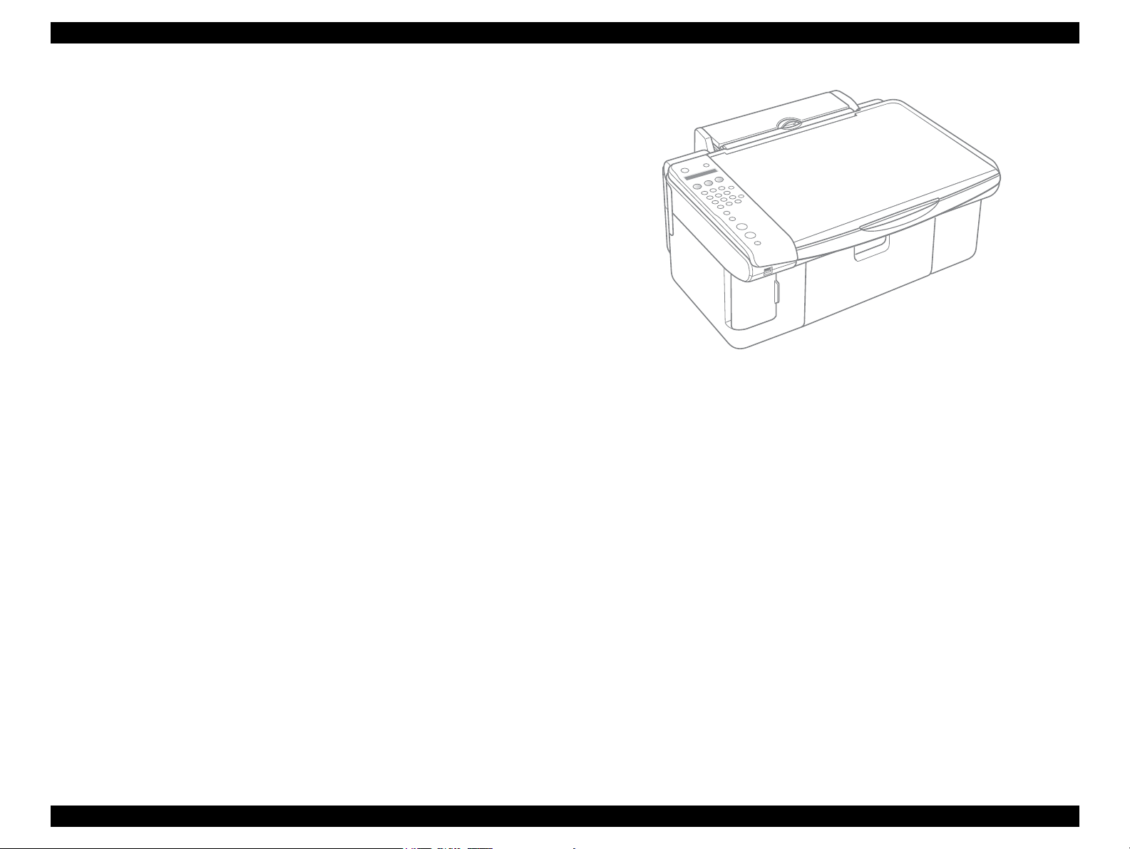
Exterior design
Employing a CIS scanner engine has achieved the smaller size.
The control panel attached on the left of the unit gives distinctive look ensuring
ease of operation.
Figure 1-1. External View
PRODUCT DESCRIPTION Overview 11
Page 12
EPSON Stylus CX5700F/CX5800F/CX6900F/CX7000F/DX7000F Revision D
C H E C K
P O I N T
#A3
#A2
#A1
BlackCyan Magenta Yellow
2.822
(40/360 inch)
A column
B column
C column
D column
#A90
#A89
#A88
#B3
#B2
#B1
#B89
#B88
#B90
#C3
#C2
#C1
#C89
#C88
#C90
#D3
#D2
#D89
#D88
#D90
#D1
8.467
(120/360 inch)
2.822
(40/360 inch)
0.2117
(3/360 inch)
0.1411
(2/360 inch)
0.07055
(1/360 inch)
Carriage Moving Direction
Paper Feed Direction
1.2 Specifications
1.2.1 Printer Specifications
This section covers specifications of Stylus CX5700F/CX5800F.
1.2.1.1 Physical Specification
Refer to 8.2.1 “Physical Specifications” (p.251) for information
unique to Stylus CX6900F/CX7000F/DX7000F.
Weight
6.8 kg (without the ink cartridges)
Dimension (the paper support and output tray are not set nor opened)
463 mm (W) x 344 mm (D) x 178 mm (H)
1.2.1.2 Printing Specification
Print Method
On demand ink jet
Nozzle Configuration
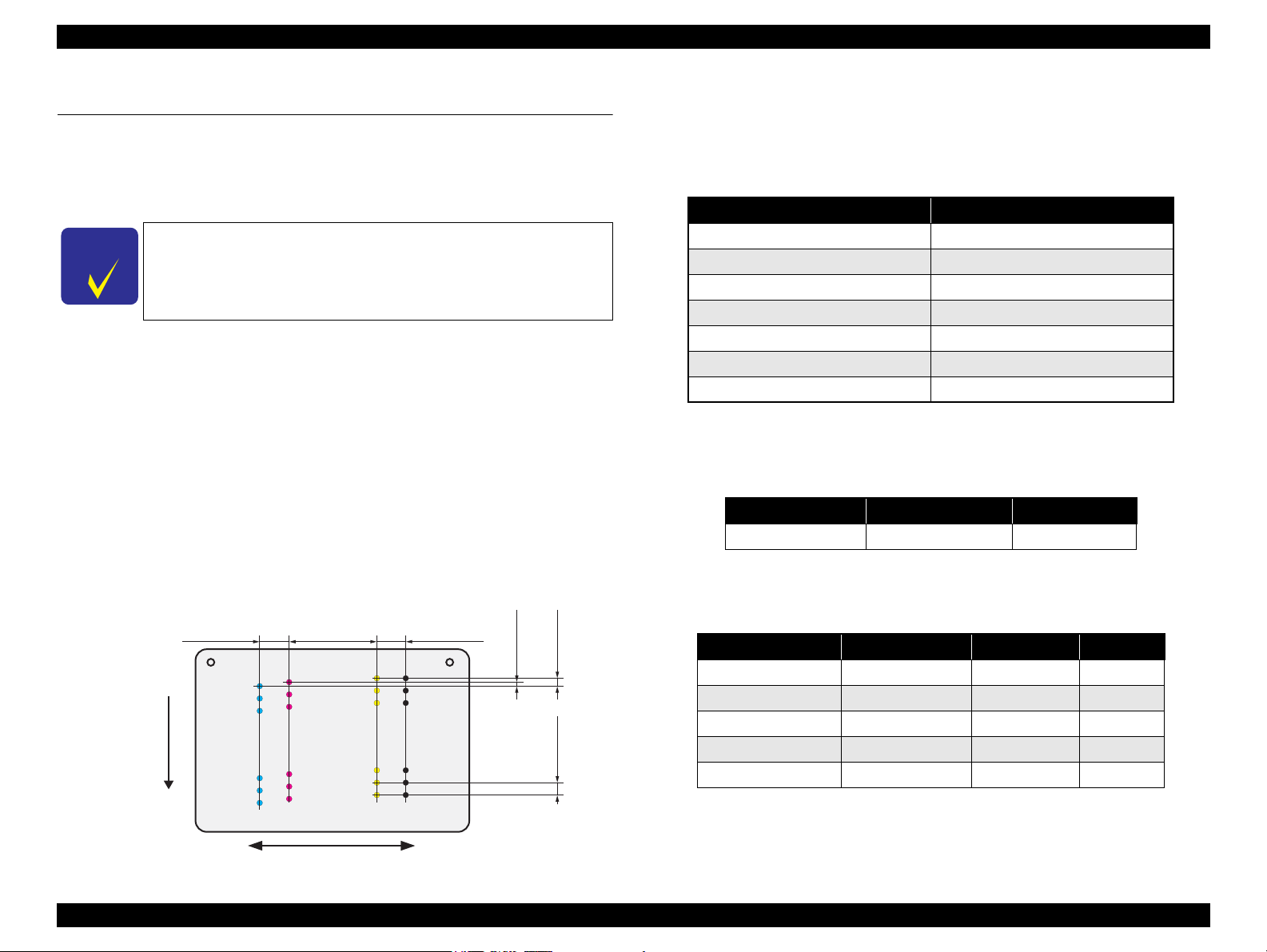
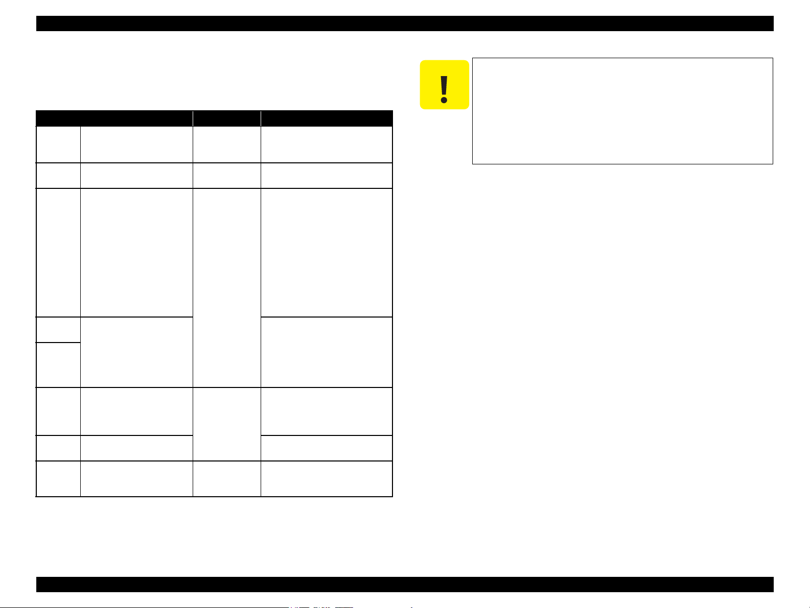
Monochrome 90 nozzles
Color 90 nozzles x 3 (Cyan, Magenta, Yellow)
Print Direction
Bi-directional minimum distance printing (with logic seeking)
Print Resolution
Table 1-2. Print Resolution
Horizontal direction (across columns) Vertical direction (paper feed)
360 dpi 120 dpi
360 dpi 360 dpi
360 dpi 720 dpi
720 dpi 720 dpi
1440 dpi 720 dpi
1440 dpi* 1440 dpi*
5760 dpi* 1440 dpi*
Note * : Those resolution are achieved only with the printer driver.
Print Speed & Printable Columns
Table 1-3. Character Mode
Character pitch Printable columns CR speed
10 CPI (Pica) 80 185 CPS*
Note * : CPS: Characters/Second
This speed is when using normal dot printing mode.
Table 1-4. Graphic Mode (Standard)
Horizontal resolution Printable area Max. dot count CR speed
360 dpi* 209.8 mm (8.26”) 2976 360 cps
PRODUCT DESCRIPTION Specifications 12
Figure 1-2. Nozzle configuration
Note * : Draft Printing
360 dpi 209.8 mm (8.26”) 2976 285 cps
720 dpi 209.8 mm (8.26”) 5952 220 cps
1440 dpi 209.8 mm (8.26”) 11904 285 cps
2880 dpi 209.8 mm (8.26”) 23808 285 cps
Page 13
EPSON Stylus CX5700F/CX5800F/CX6900F/CX7000F/DX7000F Revision D
C H E C K
P O I N T
C A U T I O N
Table 1-5. Graphic Mode (Borderless Printing)
Horizontal resolution Printable area Max. dot count CR speed
360 dpi* 215.05 mm (8.46”) 3048 285 cps
720 dpi 215.05 mm (8.46”) 6096 220 cps
1440 dpi 215.05 mm (8.46”) 12192 285 cps
2880 dpi 215.05 mm (8.46”) 24384 285 cps
Note * : Except Draft Printing
Control code
ESC/P Raster command
EPSON Remote command
ESC/P-R Level-1 command
Internal fonts
Character code: Alphanumeric with expanded graphics (PC437)
ASCII, 20H to 7FH only
Fonts: EPSON original fonts
Alphanumeric font: Courier
Input buffer size
64 Kbytes
1.2.1.3 Paper Feed Specifications
Paper feed method
Friction feed, using one ASF (Auto Sheet Feeder)
1.2.1.4 Supported Papers
Refer to 8.2.2 “Supported Papers” (p.251) for information unique
to Stylus CX6900F/CX7000F/DX7000F.
Cut sheets
Paper size
A4 210 mm 297 mm
A5 148 mm 210 mm
A6 105 mm 148 mm
B5 182 mm 257 mm
Letter
Legal
Executive
Half Letter
User
defined
50.8-329 mm
Dimensions
Width Length
215.9 mm
(8.5”)
215.9 mm
(8.5”)
184.2 mm
(7.25”)
139.7 mm
(5.5”)
1117.6 mm
Table 1-6. Cut Sheets
Thickness Weight Paper type
279.4 mm
(11”)
355.6 mm
(14”)
266.7 mm
(10.5”)
215.9 mm
(8.5”)
127-
0.08-0.11 mm
64-90 g/m
(17-24(lb))
2
Plain paper
Recycled paper
Paper path
Top feed, front out
Paper feed rates
203.2 mm/sec (8.0 inch/sec): high quality mode, 25.4-mm feed
294.64 mm/sec (11.6 inch/sec): high speed mode, continuous feed
PF (Paper Feed) interval
Programmable in 0.017 mm (1/1440 inch) steps
PRODUCT DESCRIPTION Specifications 13
Poor quality paper may reduce print quality and cause paper
jams or other problems. If you encounter problems, switch to a
higher grade paper.
It is necessary that there is no wrinkle, nap, tear, fold, and so on
in the form.
The curve of form must be 5 mm or below.
Use paper under normal conditions
• Temperature 15 to 25°C (59 to 77°F)
• Humidity 40 to 60% RH
Page 14
EPSON Stylus CX5700F/CX5800F/CX6900F/CX7000F/DX7000F Revision D
C A U T I O N
Envelopes
Table 1-7. Envelopes
Paper size
1
No.10 *
1
DL *
1
C6 *
220 x 132 *
2
Note *1 : Check that the flap is on the long edge and can be folded.
*2 : Bundled with the media such as Photo Quality Ink Jet Cards.
Dimensions
Width Length
241.3 mm
(9.5”)
104.8 mm
(4.125”)
220 mm 110 mm
Thickness Weight Paper type
N/A
75-90 g/m
(20-24(lb))
162 mm 114 mm
132 mm 220 mm 0.1 mm 82 g/m
Use paper under normal conditions
• Temperature 59 to 77°F (15 to 25°C)
• Humidity 40 to 60% RH
Poor quality paper may reduce print quality and cause paper
jams or other problems. If you encounter problems, switch to a
higher grade of paper.
It is necessary that there is no wrinkle, nap, tear, fold, and so on
in the form.
Don't use the adhesive envelopes.
Don't use sleeve insert envelopes and cellophane window
envelopes.
2
2
Bond paper
Air mail
PPC
EPSON special papers
Item Size
Bright White Ink Jet
Paper
Photo Paper
Premium Glossy Photo
Paper
Premium Semigloss
Photo Paper
Matte Paper
Heavyweight
Double-sided Matte
Paper
Economy Photo Paper
Photo Quality Ink Jet
Paper
Glossy Photo Paper
Premium Glossy Photo
Paper
*
*
*
*
*
*
Table 1-8. EPSON Special Papers
Width
(mm)
A4 210 297 0.13 92.5
4” x 6” 101.6 152.4 0.23 194
Letter 215.9 279.4
A4 210 297
8” x 10” 20.32 254
5” x 7” 127 178
4” x 6” 101.6 152.4
3R 89 127
Letter 215.9 279.4
4” x 6” 101.6 152.4
Letter 215.9 279.4
A4 210 297
Letter 215.9 279.4
A4 210 297
A4 210 297 0.23 188
A4 210 297 0.12 102
Letter 215.9 279.4
4” x 6” 101.6 152.4
4” x 6” 101.6 152.4 0.25 238
Length
(mm)
Thickness
(mm)
0.27 255
0.27 250A4 210 297
0.23 167
0.25 178
0.23 188
Weight
(g/m2)
Note * : Not supported with stand-alone functions of copy and memory card print.
PRODUCT DESCRIPTION Specifications 14
Page 15
EPSON Stylus CX5700F/CX5800F/CX6900F/CX7000F/DX7000F Revision D
C A U T I O N
Use paper under normal conditions
• Temperature 59 to 77°F (15 to 25°C)
• Humidity 40 to 60% RH
Poor quality paper may reduce print quality and cause paper
jams or other problems. If you encounter problems, switch to a
higher grade of paper.
It is necessary that there is no wrinkle, nap, tear, fold, so on in
the form.
The curve of form must be 5 mm or below.
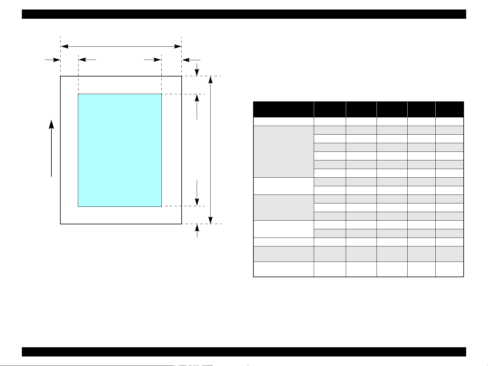
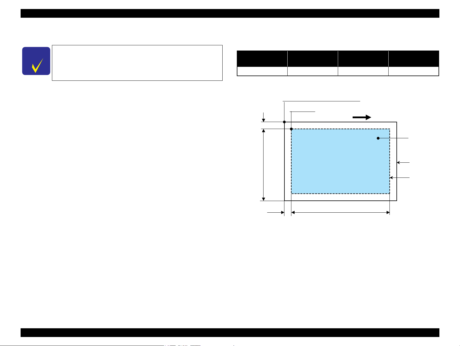
1.2.1.5 Printing Area
Cut sheet (standard printing)
Printable area
The print quality is guaranteed for the print area above 3 mm bottom margin.
For paper width (PW) and paper length (PL), refer to “ 1.2.1.4 Supported
Papers ” (p.13).
Refer to the following table. As for each margin area, refer to Figure 1-3
(p.16).
Table 1-9. Applicable Paper/Printing Area
Paper type
A4
A5
A6
B5
Letter
Legal
Cut sheets
Executive
Half Letter
User defined
Bright White Ink Jet Paper
Photo Paper
Premium Glossy Photo Paper
Premium Semigloss Photo Paper
Matte Paper Heavyweight
Double Sided Matte Paper
Economy Photo Paper
EPSON special papers
Photo Quality Ink Jet Paper
Glossy Photo Paper
Premium Glossy Photo Paper
Left
margin
3 mm
(0.12”)
3 mm
(0.12”)
Right
margin
3 mm
(0.12”)
3 mm
(0.12”)
Top
margin
3 mm
(0.12”)
3 mm
(0.12”)
Bottom
margin
3 mm
(0.12”)
3 mm
(0.12”)
PRODUCT DESCRIPTION Specifications 15
Page 16
EPSON Stylus CX5700F/CX5800F/CX6900F/CX7000F/DX7000F Revision D
Printable area
LM
RM
PW
TM
BM
PL
Paper Feed Direction
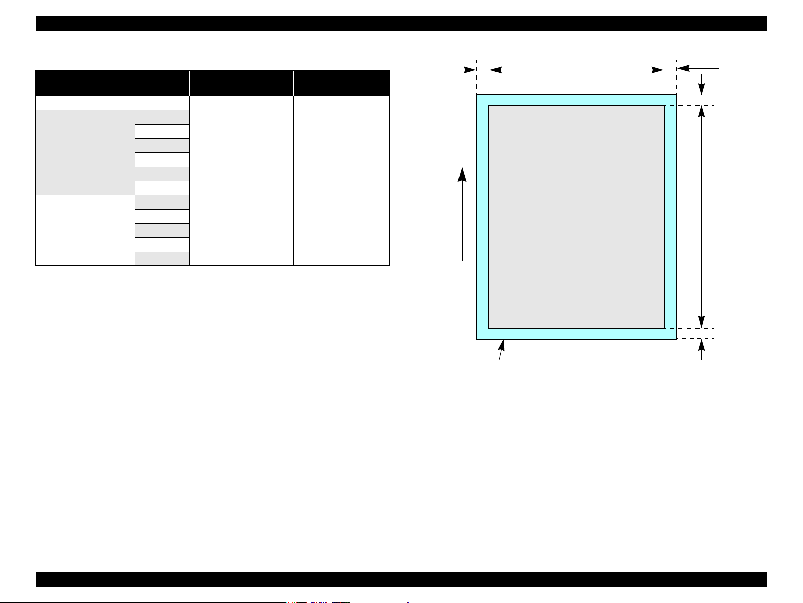
Cut sheet (borderless printing)
Printable area
For paper width (PW) and paper length (PL), refer to “ 1.2.1.4 Supported
Papers ” (p.13).
Refer to the following table. The LO, RO, TO, and BO indicate the print
margins that bleed off (extend beyond) the left, right, top, and bottom edges of
the paper. (Refer to Figure 1-4 (p.17).)
Table 1-10. Applicable Paper/Printing Area (For Printing)
Figure 1-3. Printable Area Cut Sheet (Standard Printing)
Paper Type Size
Photo Paper 4” x 6” 2.54 2.54 1.34 2.54
Letter 2.54 2.54 2.96 4.02
A4 2.54 2.54 2.96 4.02
Premium Glossy Photo
Paper
Premium Semigloss
Photo Paper
Matte Paper
Heavyweight
Double-sided Matte
Paper
Economy Photo Paper A4 2.54 2.54 2.96 4.02
Photo Quality Ink Jet
Paper
Premium Glossy Photo
Paper
8” x 10” 2.54 2.54 2.96 4.02
5” x 7” 2.54 2.54 2.96 4.02
4” x 6” 2.54 2.54 1.34 2.54
3R 2.54 2.54 1.34 2.54
Letter 2.54 2.54 2.96 4.02
A4 2.54 2.54 2.96 4.02
Letter 2.54 2.54 2.96 4.02
A4 2.54 2.54 2.96 4.02
8”x 10” 2.54 2.54 2.96 4.02
Letter 2.54 2.54 2.96 4.02
A4 2.54 2.54 2.96 4.02
A4 2.54 2.54 2.96 4.02
4”x 6” 2.54 2.54 1.34 2.54
LO
(mm)
RO
(mm)
TO
(mm)
BO
(mm)
PRODUCT DESCRIPTION Specifications 16
Page 17
EPSON Stylus CX5700F/CX5800F/CX6900F/CX7000F/DX7000F Revision D
Paper size
LO ROPW
TO
BO
Paper Feed Direction
PL
Printable area
Table 1-11. Applicable Paper/Printing Area (For Copying)
Paper Type Size
Photo Paper 4” x 6”
Letter
A4
Premium Glossy Photo
Paper
Premium Semigloss
Photo Paper
8” x 10”
5” x 7”
4” x 6”
3R
Letter
A4
5”x 7”
4” x 6”
3R
LO
(mm)
2.54 2.54 2.96 5.08
RO
(mm)
TO
(mm)
BO
(mm)
Figure 1-4. Printable Area for Cut Sheet (Borderless Printing)
PRODUCT DESCRIPTION Specifications 17
Page 18
EPSON Stylus CX5700F/CX5800F/CX6900F/CX7000F/DX7000F Revision D
Printable area
LM
TM
RM
BM
Paper Feed Direction
PW
PL
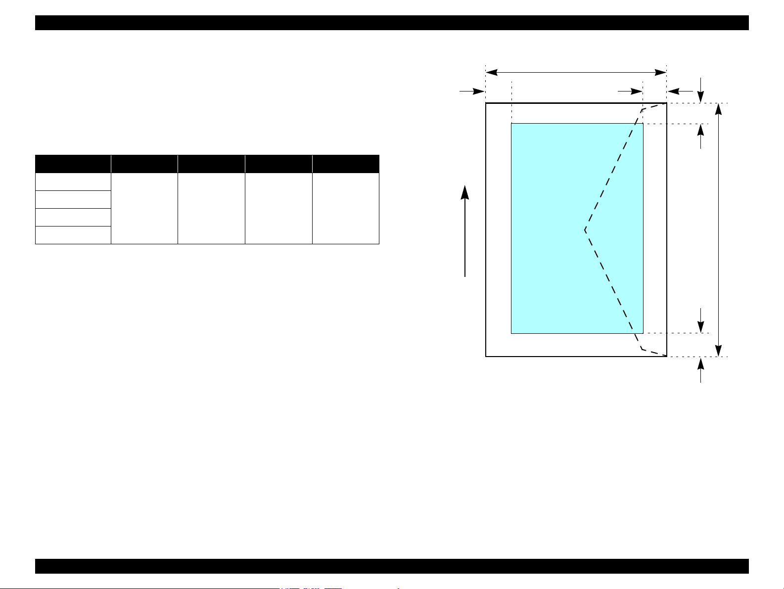
Envelopes
Printable area
For paper width (PW) and paper length (PL), refer to “ 1.2.1.4 Sup ported
Papers ” (p.13).
Refer to the following table. As for each margin area, refer to Figure 1-5
(p.18).
Table 1-12. Applicable Paper/Printing Area
Paper type Left Margin Right Margin Top Margin Bottom Margin
No.10
DL
C6
220 x 132
3 mm (0.12”) 3 mm (0.12”) 3 mm (0.12”) 20 mm (0.79”)
Figure 1-5. Printable Area for Envelopes
PRODUCT DESCRIPTION Specifications 18
Page 19
EPSON Stylus CX5700F/CX5800F/CX6900F/CX7000F/DX7000F Revision D
C H E C K
P O I N T
C A U T I O N
1.2.1.6 Ink Cartridge Specifications
Refer to 8.2.3 “Ink Cartridge Specifications” (p.252) for
information unique to Stylus CX6900F/CX7000F/DX7000F.
Type/color: EPSON special ink cartridges
Table 1-13. Ink Cartridge
Color Size CX5700F CX5800F
Black
Cyan
Magenta
Yellow
Print Capacity
Black Ink Cartridge
S size T0621 T0601
SS size T0631 ---
S size --- T0602
SS size T0632 ---
S size --- T0603
SS size T0633 ---
S size --- ---
SS size T0634 T0604
Storage Temperature
Table 1-14. Storage Temperature
Situation Storage Temperature Limit
When stored in individual boxes
When installed in main unit
-22 to 104 ºF
(-30 oC to 40 oC)
-4 to 104 ºF
o
C to 40 oC)
(-20
1 month at 104 ºF (40 oC)
Dimension: 12.7mm (W) x 73.46mm (D) x 55.25mm (H)
The ink in the ink cartridge freezes at 3.2 ºF (-16 °C) or less.
Ink thaws and is usable after approximately three hours at 77 ºF
(25 °C).
• S size: 400 pages/A4 (ISO/IEC10561 Letter Pattern at
360x720 dpi)
• SS size: 250 pages/A4 (360x720 dpi, 5% duty)
Color Ink Cartridge
• S size: 460 pages/A4 (360x720 dpi, 5% duty for each color)
• SS size: 250 pages/A4 (360x720 dpi, 5% duty for each color)
Shelf life: 6 months after opening the package
2 years without opening the package
PRODUCT DESCRIPTION Specifications 19
Page 20
EPSON Stylus CX5700F/CX5800F/CX6900F/CX7000F/DX7000F Revision D
C H E C K
P O I N T
a
Original's top left alignment position
First pixel
Scan direction
Original
(face down)
Scan bed
Scan area
RL
OTM
RW
OLM
1.2.2 Scanner Specifications
Refer to 8.2.4 “Scanner Specifications” (p.253) for information
unique to Stylus CX6900F/CX7000F/DX7000F.
1.2.2.1 Basic Specifications
Product type: Flatbed color image scanner
Scanning method: Moving carriage, stationary document
Sensor: CIS
Maximum scan area: 8.5” x 11.7” (216 mm x 297 mm)
Document sizes: A4 or US letter
Max. effective pixels: 10,200 x 14,040 pixels (1200 dpi)
Resolution
Main scan: 1200 dpi
Sub scan: 2400 dpi with Micro Step
Scanning resolution: 50 to 4800 dpi (selectable in 1-dpi steps), 7200 dpi,
9600 dpi
1.2.2.3 Image Scanning Area
Table 1-15. Image Scanning Area
RW
(readable width)
216 mm (8.5”) 1.5 mm ± 1 mm 297 mm (11.7”) 1.5 mm ± 1 mm
(out-of-range left margin)
OLM
RL
(readable length)
(out-of-range top margin)
OTM
Gradations (pixel depth): 16 bits per pixel (input)
Scanning speed: 1200 dpi
Light source: RGB Three Color LED
Color: Approx. 15 msec/line
Monochrome: Approx. 5 msec/line
1 or 8 bits per pixel (output)
Figure 1-6. Image Scanning Area
1.2.2.2 Detailed Specifications
Control commands: ESC/I D7
Gamma correction: Two user-defined levels
PRODUCT DESCRIPTION Specifications 20
Page 21
EPSON Stylus CX5700F/CX5800F/CX6900F/CX7000F/DX7000F Revision D
50/10
80/27
86/30 95/35
104/40
68/20
Temperature (ºF/°C)
20
30
40
50
90
80
70
60
Humidity (%)
1.2.3 Common
1.2.3.1 Electric Specification
Primary power input
Table 1-16. Primary Power Input
100-120 V model 220-240 V model
Rated power supply
voltage (ACV)
Input voltage range
(ACV)
Rated current (A)
Rated frequency
(Hz)
Input frequency
range (Hz)
Power consumption
(W)
(max. 0.7 A w/ card slot model)
(max. 0.7 A w/o card slot model)
(Standalone copying, ISO10561 Letter Patter, Plain Paper - Text)
100 ~ 120 220 ~ 240
90 ~ 132 198 ~ 240
0.4 A
Approx. 0.2
(Power Off Mode)
0.2 A (max. 0.3A)
(max. 0.3 A w/ card slot model)
(max. 0.3 A w/o card slot model)
50 ~ 60
49.5 ~ 60.5
Approx. 13 (w/ card slot model)
Approx. 13 (w/o card slot model)
Approx. 4.5 (Low-power Mode)
Approx. 4.0 (Sleep Mode)
Approx. 0.4
(Power Off Mode)
1.2.3.2 Environmental Performance
Table 1-17. Environmental Performance
Condition Temperature Humidity*
1
50 ~ 95 ºF
~ 35°C) *
(10
-4 ~ 104 ºF
~ 40°C)
(-20
3
20 ~ 80% *
5 ~ 85%
Operating
Not operating *
Note *1 : After unpacking (storage)
*2 : No condensation
*3 : Under the following conditions
2
3
Impact Vibration
1G,
-3
seconds
1 x 10
2G,
-3
seconds
2 x 10
0.15G
0.50G
Note 1: This product complies with the International Energy Star program.
Voltage resistance
PRODUCT DESCRIPTION Specifications 21
2: If Stylus CX5700F/CX5800F/CX6900F/CX7000F/DX7000F is not operated at all for
at least five minutes, the standby function reduces the current to the motor to conserve
power.
3: If the scanner is not operated at all for at least five minutes, the standby function
reduces the current to the motor to conserve power.
Current resistance
10MΩ or lower (tested between AC input terminal and chassis, test voltage: 500 VDC)
1500 VAC for one minute
Figure 1-7. Temperature/Humidity Range
1.2.3.3 Durability
Total print life: 10,000 pages (black only, A4), or five years
(whichever comes first)
Printhead Life: Six billion shots (per nozzle) or five years
(whichever comes first)
Scanner head (MCBF): 36,000 cycles of carriage movement
Page 22
EPSON Stylus CX5700F/CX5800F/CX6900F/CX7000F/DX7000F Revision D
1.2.3.4 Safety Standards: EMC
Table 1-18. Safety Standards: EMC
UL 60950
Safety
EMC
Telecom regulations
CSA No. 60950
NOM-019-SCFI-1998
FCC part 15 Subpart B class B
ICES003 CSA C108.8 Class B
CNS13438 Class B
CNS14336
AS/NZS CISPR22 Class B
FCC Part 68
IC CS03
COFETEL
AS/ACIF002
AS TS001
PSTN01
1.2.3.5 Acoustic Noise
Noise level
Approx. 45 dB (according to ISO7779 when for copying)
1.3 Interface
EPSON Stylus CX5700F/CX5800F/CX6900F/CX7000F/DX7000F provides the
following interface.
1.3.1 USB Interface
Standards
“Universal Serial Bus Specifications Revision 2.0”
“Universal Serial Bus Device Class Definition for Printing Devices Version
1.1” (printer unit)
“Universal Serial Bus Mass Storage Class Bulk-Only Transport Revision 1.0”
(storage unit)
Transfer rate: 480 Mbps (High Speed Device)
Data format: NRZI
Compatible connector: USB Series B
Recommended cable length: 2 m or less
Device ID
Table 1-19. Device ID (TBD)
Product Name Device ID
[00H][5AH]
MFG:EPSON;
Stylus CX5700F
Stylus CX5800F
CMD:ESCPL2,BDC,D4,ESCPR1;
MDL:Stylus[SP] CX5700F;
CLS:PRINTER;
DES:EPSON[SP]Stylus[SP] CX5700F;
[00H][5AH]
MFG:EPSON;
CMD:ESCPL2,BDC,D4,ESCPR1;
MDL:Stylus[SP] CX5800F;
CLS:PRINTER;
DES:EPSON[SP]Stylus[SP] CX5800F;
PRODUCT DESCRIPTION Interface 22
Page 23
EPSON Stylus CX5700F/CX5800F/CX6900F/CX7000F/DX7000F Revision D
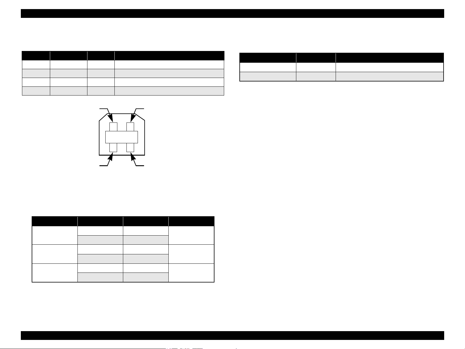
Pin #1
Pin #3
Pin #2
Pin #4
Connector signal layout
Table 1-20. Connector Pin Assignment and Signals
Pin No. Signal name I/O Function description
1 VCC - Cable power. Max. power consumption is 2 mA.
2 -Data Bi-D Data
3 +Data Bi-D Data, pull up to +3.3 V via 1.5 K ohm resistor.
4 Ground - Cable ground
Figure 1-8. USB Pin Assignment
Product ID:0x0821
Endpoint attribute
1.3.2 Fax
Table 1-22. Fax
Port name Connector Description
Line port RJ-11 Connects to phone cable from modular wall jack
EXT port RJ-11 Connects to TAM or Telephone
Note : When Auto Answer is set to “Y”, the devices such as TAM will normally answer the
call. However, Stylus CX5700F/CX5800F/CX6900F/CX7000F/DX7000F monitors the
transmitted data for a certain period of time and disconnects the “EXT” port to receive
fax data under the following conditions:
• When CNG signal is detected after the TAM answered the call.
• When CNG or any sound cannot be detected for more than 20 seconds after the TAM
answered the call.
Table 1-21. Endpoint Attribute
I/F No. Endpoint Address Endpoint Type Linked Interface
0x01 Bulk Out
0x02 Bulk In
0x04 Bulk Out
0x05 Bulk In
0x07 Bulk Out
0x08 Bulk In
Scanner
Printer
Card
0x00
0x01
0x02
PRODUCT DESCRIPTION Interface 23
Page 24
EPSON Stylus CX5700F/CX5800F/CX6900F/CX7000F/DX7000F Revision D
C A U T I O N
1.3.3 Standard Card Slots
1.3.3.1 Memory Card
Table 1-23. Memory Card
Memory card standards Slots Supported memory cards
Compact
Flash
SmartMedia
Memory
Stick
Memory
Stick PRO
Memory
Stick PRO
Duo
SD
MultiMedia
Card
xD-Picture
Card
CF+ and CompactFlash
Specification Revision 1.4
compliant
SmartMedia Standard 2000
compliant
MemoryStick Standard version
1.3 compliant
MemoryStick Standard Memory
Stick PRO Format Specifications
version 1.0 compliant
SD Memory Card Specifications
/ PART1. Physical Layer
Specification Version 1.0
compliant
MultiMedia Card Standard
compliant
xD-Picture CardTM Card
Specification Version 1.00
compliant
CF Type II slot
SmartMedia slot
Memory Stick/
Memory Stick
PRO slot
SD/MMC slot
xD-Picture Card
slot
• Compact Flash
(memory card only)
• Microdrive
SmartMedia
(maximum capacity: 128 MB)
• Memory Stick
(maximum capacity: 128 MB,
including versions with memory
select function)
• MagicGate Memory Stick
(maximum capacity: 128 MB,
copy protection function is not
supported)
• Memory Stick Duo
(requires Memory Stick Duo
adapter)
• Memory Stick Duo
(requires Memory Stick Duo
adapter)
• Memory Stick PRO Duo
(requires Memory Stick Duo
adapter)
• SD (Secure Digital) memory
card
•miniSD card
(requires SD adapter)
MultiMedia Card
xD-Picture Card
Note the following points when handling the memory card.
Since the SD card and Memory Stick share the same slot, only
one can be inserted at a time.
Since the SmartMedia and xD-Picture Card share the same slot,
only one can be inserted at a time.
When a memory card is being accessed, be sure to keep the
memory card slot's cover closed and do not touch the memory
card.
1.3.3.2 Supported Power Supply Voltage
3.3 V/ 5 V (both)
3.3 V (only)
NOTE 1: 3.3 V power is supplied to media that support both 3.3 V and 5 V.
2: Maximum current to memory card is 500 mA.
3: 5V type memory cards are not supported.
PRODUCT DESCRIPTION Interface 24
Page 25

EPSON Stylus CX5700F/CX5800F/CX6900F/CX7000F/DX7000F Revision D
1.3.3.3 Multi-slot Operations
Overview
Only one card is accessible from the computer and available for direct
printing at a time even though several different cards can be inserted into their
corresponding slots.
The slots have assigned priority to determine which slot will be accessed first
when cards are inserted in several slots at once.
To select a card that has been inserted in a non-active slot, the card in the
active slot must be removed first.
• Direct printing:
Only the image files in the active slot are valid and have assigned frame
numbers. The number of images will not change if a card is also inserted in
a non-selected slot.
• Connection to computer (Windows):
Only one drive is displayed at a time as a “removable disk” and only the
card that is in the active slot can be accessed via the removable disk. A card
that has been inserted into a non-selected slot cannot be accessed.
• Connection to computer (Macintosh):
Only the card in the active slot can be mounted on the desktop. A card that
has been inserted into a non-selected slot cannot be mounted on the desktop.
Details
Access priority
The access priority among slots is assigned as:
1: CF (Micro Drive)
2: SmartMedia/xD-Picture Card
3: Memory Stick (Memory Stick PRO)/SD (MMC)
Slot selection when power is turned on
If cards are inserted in several slots when the power is turned on, the active
slot is determined by the priority ranks listed above.
Example: If SmartMedia and Memory Stick are both inserted at power-on, the
SmartMedia slot becomes the active slot.
Slot selection after power is turned on
When a card is removed from the active slot, the slot with the next-highest
priority becomes the active slot (if a card has been inserted into it). There is no
need to re-insert any card before accessing it. If no slots contain any cards, the
highest-priority slot (CF Micro Drive) again becomes the active slot.
Cards can be removed from non-selected slots in any order.
Example: If a memory stick and CF card are inserted while SmartMedia is
selected, CF becomes selected (active) once SmartMedia is
removed.
PRODUCT DESCRIPTION Interface 25
Page 26
EPSON Stylus CX5700F/CX5800F/CX6900F/CX7000F/DX7000F Revision D
1.4 Stand-alone Copy
1.4.1 Basic Specifications
1.4.1.1 Supported Paper Sizes, Types and Qualities
Table 1-24. Supported Paper Sizes, Types and Qualities (for EAI)
Paper type
Paper name
Plain Paper Plain Paper Plain Paper Letter Letter
Premium Glossy Photo Paper Photo Paper Photo Paper
Premium Semigloss Photo Paper Photo Paper Photo Paper Letter Letter
High Gloss Photo Paper Photo Paper Photo Paper
Note *1 : The quality of draft copy is not affected by “Paper type” selection.
Panel
indication
Quality*
1
Paper size
Paper size
Letter
5” x 7”
4” x 6”
Letter
5” x 7”
4” x 6”
Panel
indication
Letter
5” x 7”
4” x 6”
Letter
5” x 7”
4” x 6”
Table 1-25. Supported Paper Sizes, Types and Qualities (for Asia, Pacific)
Paper type
*1
Paper name
Plain Paper Plain Paper Plain Paper A4 A4
Premium Glossy Photo
Paper
Premium Semigloss Photo
Paper
High Glossy Photo Paper Photo Paper Photo Paper
Note *1 : The quality of draft copy is not affected by “Paper type” selection.
*2 : For photo paper: SN, AF LUT parameter is same as Premium Glossy Photo Paper.
*3 : 10 x 15: The panel indicator only. Stylus CX5700F/CX5800F/CX6900F/
*4 : 13 x 18: The panel indicator only. Stylus CX5700F/CX5800F/CX6900F/
Panel
indication
Photo Paper Photo Paper
Photo Paper Photo Paper*2Letter Letter
CX7000F/DX7000F chalks 10 x 15 format up to 4 x 6 format.
CX7000F/DX7000F chalks 13 x 18 format up to 5 x 7 format.
Quality
*2
*2
Paper size
A4
13 x 18
10 x 15
Letter
13 x 18
10 x 15
Paper size
*4
*3
*4
*3
A4
13 x 18
10 x 15
Letter
13 x 18
10 x 15
1.4.1.2 Zoom Function
Panel
indication
*4
*3
*4
*3
The zoom function provides enlarged or reduced copies of originals. The either of the
following can be selected from the control panel.
Actual (The state which “Fit to page” is not selected. It is the power-on default.)
The zoom factor is set to 100%.
Fit to page
This function detects the image size of the original and automatically sets the
zoom factor of the copy according to the copy paper's printable area.
1.4.1.3 Number of Copies Setting
This function sets the number of copies. The setting range is 1 to 9 and 100.
1.4.1.4 Maximum Copy Size
216 mm x 297 mm
PRODUCT DESCRIPTION Stand-alone Copy 26
Page 27
EPSON Stylus CX5700F/CX5800F/CX6900F/CX7000F/DX7000F Revision D
1.4.1.5 Copy Layout
The following copy layout is provided according to “Paper type”, “Paper size” and
zoom selections.
Standard copy
Provided for ordinary use with 3mm copy margin from every side.
Borderless copy
Borderless printing of copies occurs when the print area is set as larger than the
copy paper's size. In such cases, the outer edges of the original image may be
omitted in the printed copy.
Small Margins copy
This function sets a 1.5mm margin on all four sides when printing in order to make
maximum use of the original image and copy paper.
NOTE: Only “Standard Copy” can be used in draft copy mode.
Table 1-26. Copy Layout (for EAI)
Zoom Paper type Paper size B&W / Color Layout
Letter B&W, Color Standard
4” x 6”, 5” x 7” B&W, Color Standard
Letter B&W, Color Standard
4” x 6”, 5” x 7” B&W, Color Standard
Actual*
Fit to page*
Plain Paper
1
Photo Paper Letter, 4” x 6”, 5” x 7” B&W, Color Small margin
Plain Paper
2
Photo Paper Letter, 4” x 6”, 5” x 7” B&W, Color Borderless
Table 1-27. Copy Layout (for Asia, Pacific)
Zoom Paper type Paper size B&W / Color Layout
1
Actual*
Fit to page*
Note *1 : Actual is the state that “Fit to page” is not selected.
*2 : “Fit to page” automatically sets the enlarge/reduce scale so that the entire image fits
into the printable area or the borderless area when borderless layout is selected.
When the original image is smaller than general card size (approx. 54mm x 86mm),
the print margins will be different from the one that is defined by each layout.
The image placement uses the upper left corner as the origin and any margins that
occur during the fitting process occur along the bottom and/or right edge.
Plain paper
Photo Paper A4, 10 x 15, 13 x 18 B&W, Color Small margin
Plain paper
2
Photo paper A4, 10 x 15, 13 x 18 B&W, Color Borderless
A4 B&W, Color Standard
10 x 15, 13 x 18 B&W, Color Standard
A4 B&W, Color Standard
10 x 15, 13 x 18 B&W, Color Standard
Note *1 : Actual is the state that “Fit to page” is not selected.
*2 : “Fit to page” automatically sets the enlarge/reduce scale so that the entire image fits
into the printable area or the borderless area when borderless layout is selected.
When the original image is smaller than general card size (approx. 54mm x 86mm),
the print margins will be different from the one that is defined by each layout.
The image placement uses the upper left corner as the origin and any margins that
occur during the fitting process occur along the bottom and/or right edge.
PRODUCT DESCRIPTION Stand-alone Copy 27
Page 28
EPSON Stylus CX5700F/CX5800F/CX6900F/CX7000F/DX7000F Revision D
1.4.1.6 Multiple Copies From an Original
Second and subsequent copies can be printed from an original without scanning.
When printing two or more copies, under the following settings the scan data can be
stored in the unit's memory so that the second and subsequent copies can be printed
without scanning.
“Draft” mode (monochrome/color)
“Text” mode (monochrome)
1.4.2 Copy Speed
1.4.2.1 Black Copy Speed
Plain Paper – Draft 13.4 cpm (Copy per minute), Plain Paper – 3.0 cpm
Black e-Memo text A4 size pattern, zoom 100%
The above speed is for the second and subsequent copies (the time between
ejection of the first page to ejection of the second page).
1.4.2.2 Color Copy Speed
Plain Paper – Draft 13.4 cpm (Copy per minute), Plain Paper –1.0 cpm
Color e-Memo text A4 size pattern, zoom 100%
The above speed is for the second and subsequent copies (the time between
ejection of the first page to ejection of the second page)
1.4.3 Configuration for Copying
Table 1-28. Configuration for Copying
Copy Mode setting Scan and Print configuration
Paper type
Plain Paper
Photo Paper
Draft*3
(Plain paper only)
Note *1 : “Default” is the state in which “Fit to page” is not selected. When “Fit to page” is
selected, scan resolution will be optimized according to enlarge/reduce scale.
*2 : Pure black will be used in both B&W and color mode.
*3 : With “Draft”, both real black and composite black will be used for black printing.
B&W /
*2
Color
B&W 100 (Default) 360 x 360 VSD1 Off CC2
Color 100 (Default) 360 x 720 VSD1 On CC2
B&W 100 (Default) 1440 x 720 VSD3 On CC3
Color 100 (Default) 1440 x 720 VSD3 On CC3
B&W 100 (Default) 360 x 120 Eco Off CC1
Color 100 (Default) 360 x 120 Eco Off CC1
Enlarge /
Reduce
*1
(%)
Print
resolution
(H x V dpi)
Dot size MW LUT
PRODUCT DESCRIPTION Stand-alone Copy 28
Page 29
EPSON Stylus CX5700F/CX5800F/CX6900F/CX7000F/DX7000F Revision D
a
a
Copy
Print area
Copy paper
Print direction
Scan direction
Right side of copy
Right side of original
Original
(face down)
Scan area
Scan bed
BMTM
PL
RM
LM
TopPW
*2*1
OLM
TopRW
OTM
RL
Note *1 : This indicates the top left corner of the original. Normally, this corner is aligned
with the scan bed's top right corner as the reference point.
*2 : This indicates the scan start position at the top left of the original, which
corresponds to the print start position at the top left of the copy. The bottom right
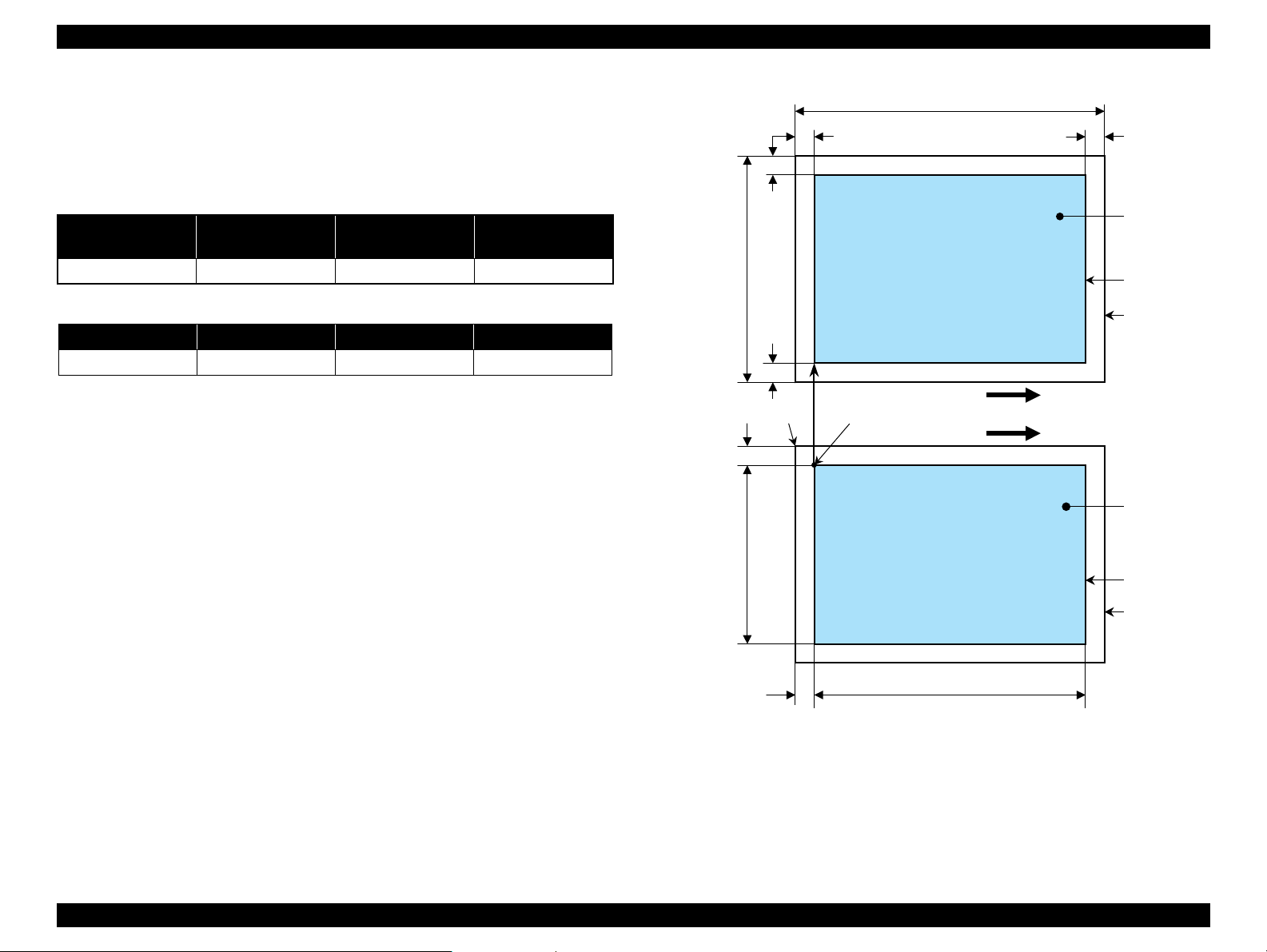
corner position of the copy is within the print area but varies according to the
enlarge/reduce setting.
1.4.4 Relation between Original and Copy
1.4.4.1 Standard Copy
The following table shows the relative positioning of the original and copy.
Table 1-29. Original (scanner)
RW
(readable width)
216 mm (8.5”) 3 mm 297 mm (11.7”) 3 mm
RM LM TM BM
3 mm (0.12”) 3 mm (0.12”) 3 mm (0.12”) 3 mm (0.12”)
Note : Refer to “ 1.2.1.4 Supported Papers ” (p.13) for paper width (PW) and paper length (PL).
(out-of-range left margin)
OLM
Table 1-30. Copy (printer)
RL
(readable length)
(out-of-range top margin)
OTM
PRODUCT DESCRIPTION Stand-alone Copy 29
Figure 1-9. Standard Copy
Page 30
EPSON Stylus CX5700F/CX5800F/CX6900F/CX7000F/DX7000F Revision D
a
a
Copy
Print area
Copy paper
Print direction
Scan direction
Right side of original
Original
(face down)
Scan area
Scan bed
BO
TO
PL
TopPW
*2*1
OLM
TopRW
OTM
RL
Note *1 : This indicates the top left corner of the original. Normally, this corner is aligned
with the scan bed's top right corner as the reference point.
*2 : This indicates the scan start position at the top left of the original, which
corresponds to the print start position at the top left of the copy. The bottom right
corner of the print area varies according to the scale setting in the print area.
Right side of copy
LO
RO
1.4.4.2 Borderless Copy
The following table shows the relative positioning of the original and copy.
Table 1-31. Original (scanner)
RW
(readable width)
216 mm (8.5”) 1.5 mm ± 1 mm 297 mm (11.7”) 1.5 mm ± 1 mm
(out-of-range left margin)
OLM
RL
(readable length)
OTM
(out-of-range top margin)
RO LO TO BO
2.5 mm 2.5 mm 3.0 mm 5.0 mm
Note : Refer to “ 1.2.1.4 Supported Papers ” (p.13) for paper width (PW) and paper length (PL).
Table 1-32. Copy (printer)
PRODUCT DESCRIPTION Stand-alone Copy 30
Figure 1-10. Borderless Copy
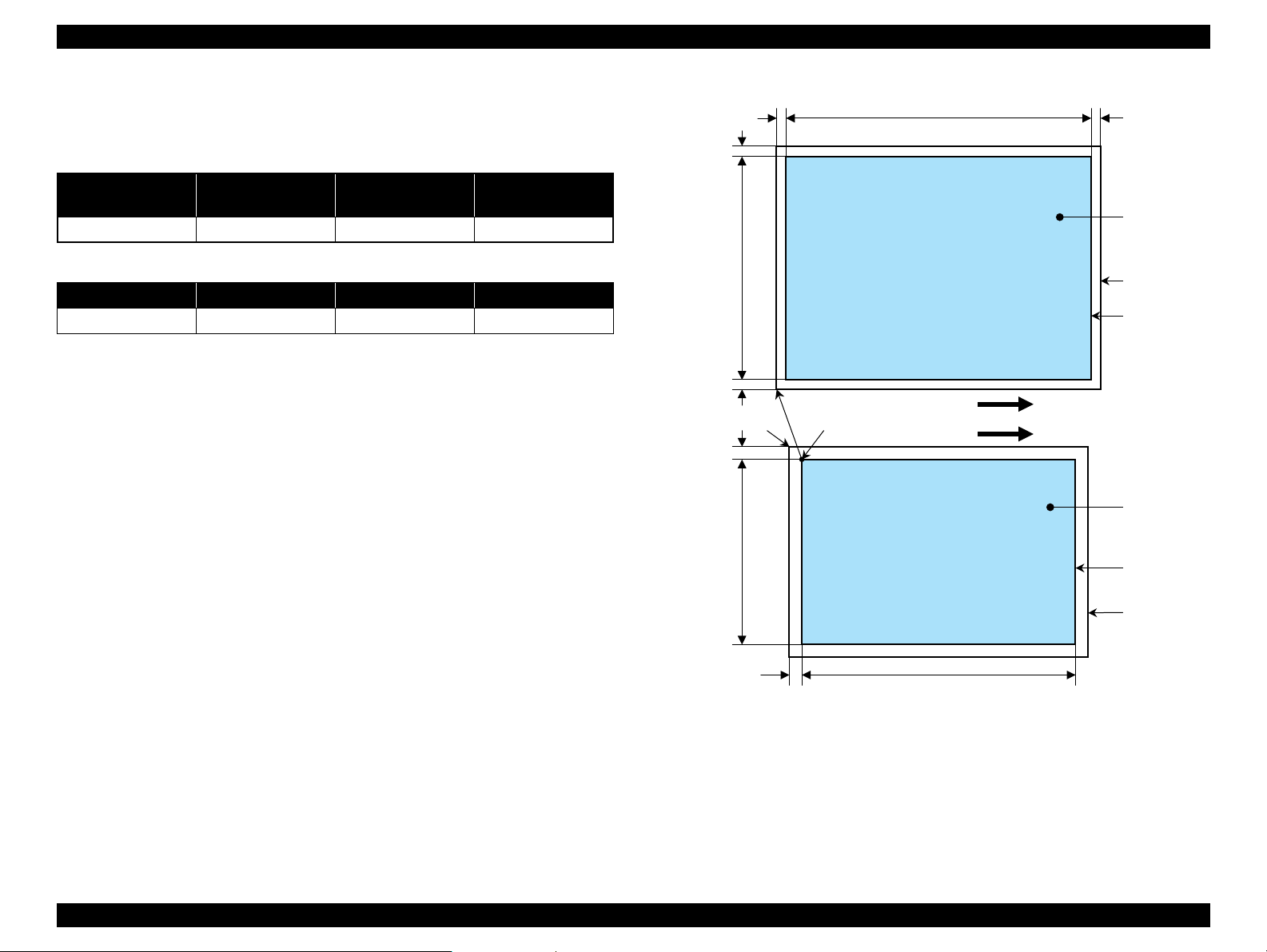
Page 31

EPSON Stylus CX5700F/CX5800F/CX6900F/CX7000F/DX7000F Revision D
a
a
Copy
Print area
Copy paper
Print direction
Scan direction
Right side of copy
Right side of original
Original
(face down)
Scan area
Scan bed
BMTM
PL
RM
LM
TopPW
*2*1
OLM
TopRW
OTM RL
Note *1 : This indicates the top left corner of the original. Normally, this corner is aligned
with the scan bed's top right corner as the reference point.
*2 : This indicates the scan start position at the top left of the original, which
corresponds to the print start position at the top left of the copy. The bottom right
corner position of the copy is within the print area but varies according to the
enlarge/reduce setting.
1.4.4.3 Small Margins Copy
The following table shows the relative positioning of the original and copy.
Table 1-33. Original (scanner)
RW
(readable width)
216 mm (8.5”) 1.5 mm ± 1 mm 297 mm (11.7”) 1.5 mm ± 1 mm
RM LM TM BM
1.5 mm 1.5 mm 1.5 mm 1.5 mm
Note : Refer to “ 1.2.1.4 Supported Papers ” (p.13) for paper width (PW) and paper length (PL).
(out-of-range left margin)
OLM
Table 1-34. Copy (printer)
RL
(readable length)
OTM
(out-of-range top margin)
PRODUCT DESCRIPTION Stand-alone Copy 31
Figure 1-11. Small Margins Copy
Page 32

EPSON Stylus CX5700F/CX5800F/CX6900F/CX7000F/DX7000F Revision D
1.5 Memory Card Print
1.5.1 Basic Specifications
1.5.1.1 File System
DCF Version 1.0 is the only file system that can be used with the product's stand-alone
printing functions. Operation is not guaranteed when any other file system is used.
The file system used by the card reader function depends on the host's specifications.
For a detailed description of the DCF specifications, see “Design Rule for Camera File
System Standard, DCF Version 2.0, JEIDA-CP-3461”.
1.5.1.2 Media Format
Media must be formatted according to DCF Version 1.0 or 2.0 standard.
DOS FAT formats (FAT12, FAT16) and single partition (basic partition)
1.5.1.3 File Formats
The file formats supported by the product are described below.
JPEG files (*.JPG)
These are photo data files that comply with the Exif Version 2.21. (Exif version
1.0/2.0/2.1/2.2/2.21)
Camera specification files (*.MRK)
These are definition files used when in camera specification mode. An
“AUTOPRINT.MRK” file whose full path name is no longer than 32 characters is
valid.
Note, however, any file that is saved in the following directories or their sub-directories
cannot be included as files to be printed.
Directories containing system properties or hidden properties
Directories that contain any double-byte characters in the directory name
“RECYCLED”: Windows directory for deleted files
“PREVIEW”: Directories containing CASIO’s DSC thumbnail images
“SCENE”: Directories containing data for CASIO’s DSC Best Shot function
“MSSONY”: Directories containing SONY’s DSC e-mail image data, voice
memos, video files, or non-compressed images
1.5.1.4 Valid Image Size
The maximum image size handled by the product is:
Horizontal: 80 X 9200 (pixels)
Vertical: 80 Y 9200 (pixels)
1.5.1.5 Maximum Number of Photo Data Files
The product can handle up to 999 photo data files. If the amount of photo data to be
recorded exceeds the capacity of one memory card, the product uses file sorting rules
to sort the photo data into valid photo data in frames numbered from 1 to 999.
Although it is possible to print photo data files with frame numbers over 999 that have
been specified for printing by camera specification files, the maximum number of
frames that can be specified is 999 frames.
If you insert a memory card that contains over 999 photo data files, only files up to 999
will be printed by the “Print All” or “Print index sheet” functions.
1.5.1.6 Thumbnail Image Data
The product handles thumbnail image data in the DCF Version 1.0 or 2.0 format (Exif
format, 160 x 120 pixels).
During the product's Index Sheet and memory card printing modes, the layout is 80
thumbnails per sheet (when using plain paper or special paper in high-speed print
mode).
1.5.1.7 File Sorting
The product stores all photo data files in the memory, using the photo data files' fullpath file names (for example, “\CIM\100EPSON\EPSN0000.JPG”), and assigned
photo frame numbers. Since photo frame numbers are assigned based on the product's
own proprietary file sorting rules, the assigned frame numbers do not necessarily
match those indicated by digital cameras.
“DCIM¥ALBUM¥IMAGE”: Directories containing CASIO’s DSC album data
save directory.
PRODUCT DESCRIPTION Memory Card Print 32
Page 33

EPSON Stylus CX5700F/CX5800F/CX6900F/CX7000F/DX7000F Revision D
1.5.1.8 File Sorting Rules
The product sorts photo data files based on the following prioritization rule.
File name is sorted in ASCII order as full path name.
NOTE: Sorting results are not guaranteed if two files have the same full-path file
names. (The same full-path file names are not allowed under the DOS
specification.)
1.5.1.9 Rules for Acquisition of Date/Time Data
The following priorities are used to fetch date and time information from photo data files.
1. Date/time data that complies with the standard format (Exif) for digital
cameras
2. Date/time data that complies with the DOS standard file system (file time
stamps)
3. Fixed values (01/01/1980, 00:00:00)
Note that the date/time data assigned to individual photo data files does not necessarily
match the date/time when the photo was actually taken. The photo date/time may be
modified due to the digital camera's calendar settings (presence/absence of functions,
incorrect date/time settings, etc.), processing of the photo data after the photo was
taken, or subsequent saving of data. In such cases, the product performs the relevant
processing based on the most recently modified date/time data.
1.5.2 Functions
1.5.2.1 List of Functions
The memory card print menu and its settings are listed in the following table.
The values shown in this table indicate the total number of options and the number of
pages or copies that can be printed consecutively.
Table 1-35. List of Functions
Memory card
printing
Print index sheet Print Index Sheet None Plain Paper 1 1
Print from index
sheet
Print all images Print All / DPOF
DPOF * Print All / DPOF
Note * : It is available only DPOF file exists in the memory card.
Note : “Print index sheet” will be selected as default function of Memory Card Print. But when
DPOF file exists in the memory card, “Print All / DPOF” will be selected as default and
DPOF print can be done easily.
Mode selection Layout Paper type
Print From Index
Sheet
• Standard
• Borderless
• Standard
• Borderless
• Standard
• Borderless
• Plain Paper
• Photo Paper
• Plain Paper
• Photo Paper
• Plain Paper
• Photo Paper
Paper
size
2
2 1
2 1 to 99
Copies/
(according
to marking)
image
1 to 3
1.5.1.10 Number of Sheets which can be Printed in Total
Up to 99 images stored on a card can be printed continuously and up to 99 copies of
each image can be specified.
PRODUCT DESCRIPTION Memory Card Print 33
Page 34

EPSON Stylus CX5700F/CX5800F/CX6900F/CX7000F/DX7000F Revision D
1.5.2.2 Memory Card Printing Mode
Print index sheet printing
This function prints thumbnail images (stored in the memory card) onto an Index
Sheet (form) for selecting images to be printed.
The combinations of paper types and paper sizes are fixed as shown right.
Print from index sheet printing
This function prints images selected using the Index Sheet.
Print all images
This function prints all images up to 999 stored in the memory card. The number
of copies per image is fixed to one.
DPOF printing
In this mode, the photo frame numbers previously specified via the camera are
printed in the number of pages specified via the camera. Only the paper type and
layout are specified on the printer side. If the layout assigned multiple photos per
output sheet, photos that have different frame sizes are automatically assigned in
the specified number of pages in numerical order (of the specified photo frame
numbers). If index print mode was set via the camera, the product will print in
DPOF index layout. (When in DPOF print mode, the mode cannot be switched by
writing the print file specification from the host after inserting the memory card.)
Table 1-36. Memory Card Printing Mode
Setting Memory card printing mode Description Option, setting range, etc.
Layout
(no menu)
Paper
type
Paper size
Pages/
copies
Quality
• Print from index sheet printing
• Print all images
• DPOF printing
Print index sheet printing Fixed Plain Paper
• Print from index sheet printing
• Print all images
• DPOF printing
Print index sheet printing Fixed A4 or Letter
• Print from index sheet printing
• Print all images
• DPOF printing
Print index sheet printing Fixed
Print from index sheet printing
Print all images
DPOF printing
Print index sheet printing Fixed
• Print from index sheet printing
• Print all images
• DPOF printing
Sets print
layout
Sets paper
type
Sets paper
size
Sets number
of printout
Sets number
of printout
Sets number
of printout
Sets print
quality
Fixed in combination with paper
type and paper size (refer to
“ 1.5.4 Layout and Paper Type,
Paper Size ” (p.38))
Plain Paper or Photo Paper
A4, 10cm x 15cm, or
13cm x 18cm
Letter, 4” x 6”, or 5” x 7”
Fixed as 1 page (can vary
according to the number of
image files)
1 to 3 (set by the marking to the
index sheet)
1
The number of copies specified
via the camera is used. The
setting range is 1 to 99 copies
(default is 1 copy).
Prints it by the quality of 360 x
720dpi of Plain Paper. Only the
Color print is supported.
Fixed according to paper type
(refer to “ 1.5.9 Relation
between Paper Type and
Quality ” (p.43))
Note : Letter, 4” x 6”, 5” x 7”: for EAI
A4, 13x18, 10x15: for Asia, Pacific
PRODUCT DESCRIPTION Memory Card Print 34
Page 35

EPSON Stylus CX5700F/CX5800F/CX6900F/CX7000F/DX7000F Revision D
1.5.3 Index Sheet
30 thumbnail images are assigned per index sheet.
There are three marking areas for each thumbnail and you can set the number of
copies up to three.
“Paper type” and “Paper size” can be set from the control panel.
The layout is fixed according to the paper type and it is not indicated on the sheet.
(Refer to
Images are arranged on the Index Sheet in ascending order (of image file number).
(Refer to
Index Sheet will be printed from the last page, in descending order. (The sheet
containing first thumbnail comes top of printouts.)
When “Print index sheet” is complete successfully, the unit automatically
switched to “Print from index sheet” function.
“ 1.5.4 Layout and Paper Type, Paper Size ” (p.38))
“ 1.5.1.7 File Sorting ” (p.32) and “ 1.5.1.8 File Sorting Rules ” (p.33))
Figure 1-12. Sample of Index Sheet
PRODUCT DESCRIPTION Memory Card Print 35
Page 36

EPSON Stylus CX5700F/CX5800F/CX6900F/CX7000F/DX7000F Revision D
a
Scan direction
Scan area
OLM
RW
OTM
RL
Original's top left alignment position
First pixel
Set original face down,
with top aligned in the
direction of the origin.
Scan bed
Operator's side
1.5.3.1 Rules for Scanning Index Sheets
Index Sheet scan range
Setting an index sheet in scanner
• Place the sheet face down on the scan bed as described below.
Align the corner of the sheet to the upper left origin point on the scan bed
and make sure the sheet is not skewed. Skewed sheet is allowed as long as
the sheet remains within the scan bed's scan range (the maximum skewing
angle is about 2.8°).
• The cover must be closed on the original to enable scanning. (This is to
prevent any shifting of the position marks while scanning).
• Do not use paper that allows images to “bleed through” to the rear side.
(This is to prevent empty bubbles from being filled in by “bleed-through”.)
Set scan area and original
Table 1-37. Set Scan Area and Original
RW
(readable width)
216 mm (8.5”) 1.5 mm ± 1 mm 297 mm (11.7”) 1.5 mm ± 1 mm
(out-of-range left margin)
OLM
RL
(readable length)
OTM
(out-of-range top margin)
Place the Index Sheet face down with its top edge aligned to the left edge of
the scan bed, and with the corner of the paper set to the original's top left
position.
PRODUCT DESCRIPTION Memory Card Print 36
Figure 1-13. Set Scan Area and Original
Page 37

EPSON Stylus CX5700F/CX5800F/CX6900F/CX7000F/DX7000F Revision D
1 2 3 1 2 3
1 2 3 1 2 3
OK patterns
NG patterns
Basic specifications for scanning of index sheets
Scanning rules for index sheet
The existence of the following recognition factors is judged using the image
pattern matching. (Image is binary.)
Table 1-38. Symbols Check
Position mark Image Description Remarks
Left and right edges (1 each)
Block codes (30)
Image marks (30 x 3)
Paper type/Paper size (6) Select paper NG if dirty (not scannable)
Layout (2) Select layout NG if dirty (not scannable)
Date format Date format On/Off Optional
Reference point for
index marks
Sheet information
(memory card ID, page)
Determines whether or
not to print pixel
NG if dirty (not scannable)
NG if dirty (not scannable)
Use at least one of these
marks
• When two or three marks of one image are filled, larger number will be used
for the number of copies. (ex. 1 and 3 are filled, number of copies is 3.)
• When the optional “ALL” mark is filled, all images in the sheet will be
printed one by one regardless of each image mark is filled or not.
• Index Sheet error will be caused when any of image mark or “ALL” mark is
not filled.
• Index Sheet error will be caused when “Left and right edges”, “Right top
EPSON” and “Block codes” are not found correctly due to something like
smear.
• Place the index sheet so that the “Left top triangle” can meet the left top
corner of the scanner.
<OK/NG mark samples>
• The marks can be recognized if 50 % or more portion of each of them is
filled.
• For running out and excessive marking out, the two white/black search
patterns shown above are superimposed on the mark, and judgment is made
according to this matching ratio. The judgment criteria is as follows.
Black matching: 80 % or more White matching: 50% or more.
Errors during scanning or printing of index sheets
• Stops scanning and returns to the menu screen if the card is removed while
an index sheet is being scanned or printed.
• Index Sheet error (No index sheet) is displayed if the sheet cannot be
scanned because it is dirty, set backwards, etc.
• Index Sheet error (Incorrect marking) is displayed if the image bubbles
cannot be read because they are not filled in correctly.
• Index Sheet error (Incorrect card) is displayed if, after printing an index
sheet, you try to print from a non-matching memory card, such as a different
(replacement) card or a re-edited version of the same card.
Figure 1-14. Symbols Check
Figure 1-15. OK/NG Mark Samples
PRODUCT DESCRIPTION Memory Card Print 37
Page 38

EPSON Stylus CX5700F/CX5800F/CX6900F/CX7000F/DX7000F Revision D
These parts are trimmed.
Photo frame
(print area)
The image below shows an example in which the photo data is aligned vertically
with the photo frame.
The image below shows an example in which the photo data is aligned
horizontally with the photo frame.
Photo frame
(print area)
These parts are
trimmed.
1.5.4 Layout and Paper Type, Paper Size
The layout/paper type and size combinations that can be selected are listed below.
Table 1-39. Layout and Paper Type, Paper Size
Layout Paper type Paper size Description
Borderless Photo Paper Letter, 4 x 6, 5 x 7
1-up with
borders
20-up — 4 x 6
30-up — 5 x 7
80-up — 4 x 6, 5 x 7
Plain Paper Letter, 4 x 6, 5 x 7
1.5.5 Options
Prints with no margins along top,
bottom and both sides
Prints with 3 mm margins along top,
bottom and both sides
Prints 20 frames per page, laid out in
5 columns and 4 rows (For DPOF
index print only)
Prints 30 frames per page, laid out in
6 columns and 5 rows (For DPOF
index print only)
Prints 80 frames per page, laid out in
10 columns and 8 rows (For DPOF
index print only)
1.5.6 Trimming Function
A trimming function is provided as a means of coordinating photo data with the types
of photo frames handled by the product. This function is always activated so that
printing photo data is in shapes that fit these photo frames.
This function is described briefly below.
The printed photo frame and the photo to be printed are matched in length along one
side and the photo is resized along the perpendicular side to fit the frame on that side.
Any part of the photo that does not fit within the photo frame is trimmed away (not
printed).
The functions below will be available by marking to options on the index sheet.
Prints all photos one by one shown on the index sheet.
PRODUCT DESCRIPTION Memory Card Print 38
Figure 1-16. Trimming Function
Page 39

EPSON Stylus CX5700F/CX5800F/CX6900F/CX7000F/DX7000F Revision D
Top edge
<Borderless>
<1 sheet with borders>
12345678
9 10111213141516
17 18 19 20 21 22 23 24
25 26 27 28 29 30 31 32
33 34 35 36 37 38 39 40
41 42 43 44 45 46 47 48
49 50 51 52 53 54 55 56
57 58 59 60 61 62 63 64
65 66 67 68 69 70 71 72
73 74 75 76 77 78 79 80
12345
678910
11 12 13 14 15
16 17 18 19 20
21 22 23 24 25
26 27 28 29 30
<30-up>
<80-up>
<20-up>
1.5.7 Assignment Rules for Photo Frame Numbers and Rotation
The rules concerning photo frame numbers that are referred to when assigning photos are
described below. The numbers shown in each diagram and photo frame below indicate the
photo frame numbers used for various types of layout.
The direction of the number shown in each photo frame matches the direction of the
printed photo to which the horizontal photo data was allocated. When there are more pixels
vertically than horizontally, the vertical photo data is allocated instead, and the number
shown in the figure below is then rotated 90° before being printed.
In Index printing mode, the numbers are printed as they are shown below, regardless of the
shape of the photo data. However, when the photo data has an equal number of pixels
vertically and horizontally the photos are printed without rotation, regardless of the layout.
(Note: the vertical photo data refers to when the photo data file itself is set for a vertical
(portrait) orientation. Photo data is defined as the vertical photo data if it is taken by a
digital camera with a portrait position detecting function.)
Figure 1-17. Assignment Rules for Photo Frame Numbers and Rotation (1)
PRODUCT DESCRIPTION Memory Card Print 39
Figure 1-18. Assignment Rules for Photo Frame Numbers and Rotation (2)
Page 40

EPSON Stylus CX5700F/CX5800F/CX6900F/CX7000F/DX7000F Revision D
Paper
A
C
FE
G
H
BD
Printable
area
1.5.8 Layout Drawings
1.5.8.1 Borderless
Figure 1-19. Borderless
Table 1-40. Borderless (unit: mm (inch))
Paper type A B C D E F G H
Letter
4” x 6”
5” x 7”
A4 210 297 215.08 305.04 2.54 2.54 2.96 4.02
10 x 15 101.60 152.40 106.68 160.53 2.54 2.54 2.82 3.60
13 x 18 127 178 132.08 186.04 2.54 2.54 2.96 4.02
Note : Letter, 4” x 6”, 5” x 7”: for EAI
A4, 13x18, 10x15: for Asia, Pacific
215.90
(8.50)
101.60
(4.00)
(5.00)
127
279.40
(11.00)
152.40
(6.00)
178
(7.00)
220.98
(8.70)
106.68
(4.20)
132.08
(5.20)
287.53
(11.32)
160.53
(6.32)
186.04
(7.32)
2.54
(0.10)
2.54
(0.10)
2.54
(0.10)
2.54
(0.10)
2.54
(0.10)
2.54
(0.10)
2.96
(0.12)
2.82
(0.11)
2.96
(0.12)
4.02
(0.16)
3.60
(0.14)
4.02
(0.16)
PRODUCT DESCRIPTION Memory Card Print 40
Page 41

EPSON Stylus CX5700F/CX5800F/CX6900F/CX7000F/DX7000F Revision D
Printable area
C
A
F
E
G
H
DB
1.5.8.2 1-up with Borders
Figure 1-20. 1-up with Borders
Table 1-41. Borderless (unit: mm (inch))
Paper type A B C D E F G H
Letter
4” x 6”
5” x 7”
A4 210 297 204 291 3.00 3.00 3.00 3.00
10 x 15 101.60 152.40 95.60 146.40 3.00 3.00 3.00 3.00
13 x 18 127.0 178.0 121.0 172.0 3.00 3.00 3.00 3.00
Note : Letter, 4” x 6”, 5” x 7”: for EAI
A4, 13x18, 10x15: for Asia, Pacific
215.90
(8.50)
101.60
(4.00)
127.0
(5.00)
279.40
(11.00)
152.40
(6.00)
178.0
(7.00)
209.90
(8.26)
95.60
(3.76)
121.0
(4.76)
273.40
(10.76)
146.40
(5.76)
172.0
(6.76)
3.00
(0.12)
3.00
(0.12)
3.00
(0.12)
3.00
(0.12)
3.00
(0.12)
3.00
(0.12)
3.00
(0.12)
3.00
(0.12)
3.00
(0.12)
3.00
(0.12)
3.00
(0.12)
3.00
(0.12)
PRODUCT DESCRIPTION Memory Card Print 41
Page 42

EPSON Stylus CX5700F/CX5800F/CX6900F/CX7000F/DX7000F Revision D
A
K
L
J
D
EF
G
H
B
J
J
J
C
II
I
D
E
F
G
H
C
B
A
I
J
1.5.8.3 20-up
Paper type A B C D E F G H I J K L
101.60
4” x 6”
10cm x 15cm 101.60 152.40 20.00 20.00 6.10 6.30 19.80 20.30 3.00 3.00 89.30 112.30
Note : Letter, 4” x 6”, 5” x 7”: for EAI
A4, 13x18, 10x15: for Asia, Pacific
(4.00)
152.40
(6.00)
Figure 1-21. 20-up
Table 1-42. 20-up (unit: mm (inch))
20.00
20.00
(0.79)
(0.79)
6.10
(0.24)
6.30
(0.25)
19.80
(0.78)
20.30
(0.80)
(0.12)
3.00
3.00
(0.12)
89.30
(3.52)
112.30
(4.42)
1.5.8.4 30-up
Figure 1-22. 30-up
Table 1-43. 30-up (unit: mm (inch))
Paper
type
5” x 7”
13 x 18 127.00 128.00 20.0 20.0 4.5 4.5 14.0 14.0 4.5 6.0
Note : Letter, 4” x 6”, 5” x 7”: for EAI
A B C D E F G H I J
127.00
(5.00)
178.00
(7.00)
20.0
(0.79)
20.0
(0.79)
4.5
(0.18)
4.5
(0.18)
14.0
(0.55)
14.0
(0.55)
A4, 13x18, 10x15: for Asia, Pacific
4.5
(0.18)
6.0
(0.24)
PRODUCT DESCRIPTION Memory Card Print 42
Page 43

EPSON Stylus CX5700F/CX5800F/CX6900F/CX7000F/DX7000F Revision D
B
C
D
E
F
G
H
I
J
K
L
M
N
O
P
Q
1.5.8.5 80-up
1.5.9 Relation between Paper Type and Quality
In this mode, printing is always in color (CMYK), not black ink only.
Table 1-45. Relation between Paper Type and Quality
Paper type
Plain Paper 720 x 720 VSD3 On 1
Photo Paper 1440 x 720 VSD3 On 2
Index Sheet
(Plain Paper)
Print resolution
(H x V dpi)
360 x 720 VSD1 On 4
Dot size MW LUT
Figure 1-23. 80-up
Paper
type
Letter
Paper
type
Letter
PRODUCT DESCRIPTION Memory Card Print 43
A B C D E F G H I
215.90
(8.50)
A4 210.0 297.0 20.0 20.0 2.0 5.0 18.0 62.0 106.0
163.32
(6.43)
A4 150.0 18.0 26.0 76.0 126.0 176.0 226.0 26.0
279.40
(11.00)
J K L M N O P Q
6.35
(0.25)
Table 1-44. 80-up (unit: mm (inch))
20.07
(0.79)
11.94
(0.47)
20.07
(0.79)
64.26
(2.53)
6.10
(0.24)
116.59
(4.59)
6.10
(0.24)
168.91
(6.65)
6.35
(0.25)
221.23
(8.71)
58.67
(2.31)
11.94
(0.47)
111.00
(4.37)
Page 44

EPSON Stylus CX5700F/CX5800F/CX6900F/CX7000F/DX7000F Revision D
1.6 Fax Function
1.6.1 Basic Specifications
Scan
Item Description
Standard (204 dpi x 98 dpi) as a threshold
B/W
Resolution
Contrast Three levels
Scan size Fixed to 216 mm x 297 mm
Maximum scan size 2.3 Mbyte
Dialing
Item Description
Speed dial 60 entries
Direct dial 64 digits
Redial Attempt: Fixed to two times
Interval Fixed to one minute
Buffer Last one number
Dial mode Tone/Pulse
Note : The product does not support PBX.
Fine (204 dpi x 196 dpi) as a threshold
Photo (204 dpi x 196 dpi) with error diffusion
Color 200 dpi x 200 dpi
Print
Item Description
Prints max. 28 digits*1.
Fax header
Paper size Letter/A4/Legal
Paper type Fixed to plain
Automatic reduction
Backup fax reception and reprint
List
Size mismatch Print (the data is printed on the current paper)
Footer No
Note *1 : Excluding phone number (20 digits).
*2 : When automatic reduction is set to on, data whose size is larger than that of the paper
will automatically be reduced so that the longer side of data fits the longer side of the
paper. Its horizontal to vertical ratio will be maintained.
*3 : Received fax data (oldest data) may be deleted in the following cases:
• When scanning for fax.
• When printing fax report (including fax log, last transmission, and speed dial list).
• When incoming call is detected. (The memory (100 Kbyte) is used to monitor the
telephone line for 60 seconds after the incoming call is detected.)
• When new fax data is received.
• When reprinting data stored in the memory. (Backup data is duplicated when
reprinted.)
*4 : When the unit is turned off, backup data will be lost.
*5 : After printing, the message that asks the user whether to reprint or not
(Reprint fax? 1:Y 2:N) appears on the LCD display.
*2
*3*4
a-z, A-Z, 1-9, 0, space, @ . _ - & / : ; , ? * ( ) ' = + #
! % ~
Supported (either On or Off can be selected.)
Yes (prints all pages in memory)
Last transaction (off/send error/every send)
Power fail report
Fax log (last 30 transactions)
Speed dial list
*5
PRODUCT DESCRIPTION Fax Function 44
Page 45

EPSON Stylus CX5700F/CX5800F/CX6900F/CX7000F/DX7000F Revision D
Transmission
Item Description
Color Direct transmission
Monochrome Memory transmission
Multi-page 100 pages
Manual send/receive Supported
Communication
Item Description
Region US/Canada/Mexico/Australia/Taiwan
*1
ECM
Supported fax standard G3/Super G3
Transmission and modulation method V.17/V.34
Transmission speed
*2
Codec
Note *1 : When ECM is off, V.34 is also set to off. In color mode, ECM automatically turns to on.
*2 : The transmission speed is determined automatically by negotiating with the other
party according to the fax protocol.
Supported (either On or Off can be selected.)
33600/26400/21600/14400/12000/9600/7200/4800/
2400 bps
B/W MMR, MR, MH
Color Jpeg
Answering
Item Description
Auto answer On/Off by answer mode button
DRD All/Single/Double/Triple
*
TAM I/F Yes
Note * : Ringer patterns of each setting are described below:
• Single: 2 sec (1.75sec ~ 2.5 sec) ON / 4 sec (3.55 sec ~ 4.45 sec) OFF,
then repeat.
• Double: 0.8 sec (0.65 sec ~ 0.95 sec) ON / 0.4 sec (0.35 sec ~ 0.5 sec) OFF/
0.8 sec (0.65 sec ~ 0.95 sec) ON / 4 sec (3.55 sec ~ 4.45 sec) OFF,
then repeat.
• Triple: 0.4 sec (0.35 sec ~ 0.5 sec) ON / 0.2 sec (0.13 sec ~ 0.28 sec) OFF/
0.4 sec (0.35 sec ~ 0.5 sec) ON / 0.2 sec (0.13 sec ~ 0.28 sec) OFF/
0.8 sec (0.65 sec ~ 0.95 sec) ON / 4 sec (3.55 sec ~ 4.45 sec) OFF,
then repeat.
• Double & Triple
0.8 sec (0.65 sec ~ 0.95 sec) ON / 0.4 sec (0.35 sec ~ 0.5 sec) OFF/
0.8 sec (0.65 sec ~ 0.95 sec) ON / 4 sec (3.55 sec ~ 4.45 sec) OFF/
0.4 sec (0.35 sec ~ 0.5 sec) ON / 0.2 sec (0.13 sec ~ 0.28 sec) OFF/
0.4 sec (0.35 sec ~ 0.5 sec) ON / 0.2 sec (0.13 sec ~ 0.28 sec) OFF/
0.8 sec (0.65 sec ~ 0.95 sec) ON / 4 sec (3.55 sec ~ 4.45 sec) OFF,
then repeat.
Memory
Item Description
Memory size for fax processing 3.5 Mbyte (SDRAM)
Note : The memory for fax processing is used to scan data for fax, print fax data or report,
monitor the telephone line, and back up received fax data.
PRODUCT DESCRIPTION Fax Function 45
Page 46

EPSON Stylus CX5700F/CX5800F/CX6900F/CX7000F/DX7000F Revision D
1.7 Control Panel
1.7.1 Buttons
The control panel contains 24 buttons. The buttons are the following 12 buttons and a
numeric keypad, which are used to set and execute various operations. All of them are
non-lock type buttons.
Table 1-46. Buttons
Button Function
Power Button Execute turning on/off the product.
Setup Button Make transition from other modes to “Setup mode”.
Memory Card Button
Copy Button
FAX Button Make transition from other modes to “FAX mode”.
Paper Type Button
Paper Size Button
Answer Button
Pause/Redial Button Call of Redial number or “Pause” input
B&W Start Button *
Color Start/OK Button Start card print or color copy.
Cancel/Back Button Stop job of copying or printing or sometimes work as shift button.
Make transition from other modes to “Memory Card mode” and
selects one of card print mode.
Make transition from other modes to “Copy mode” and sets
number of copies.
Fax mode/Setup mode: Moves the cursor on the panel display
(Up or Left).
Rest: Select paper type.
Fax mode/Setup mode: Moves the cursor on the panel display
(Right or Down).
Rest: Select paper size.
Fax mode: Space key
Rest: Selects one of Answer mode.
1
Start monochrome copy.
1.7.2 Indicators
The control panel contains following LCD (1 line x 16 characters) and 10 LEDs, which
are used to indicate various status.
Table 1-47. Indicators
LED Function
Power LED [Green] *1Light at stand-by. Blink while some operation is proceeding.
Copy LED [Green] *2Lights while Copy function is ready or proceeding.
Memory card LED
[Green] *
Fax LED [Green] *
Paper Type LED 1,2 Light one of them showing which paper type below is selected.
Paper Size LED 1,2 Light one of them showing which paper size below is selected.
Card Access LED
[Green] *
Note *1 : All LEDs except for Power LED will be turned off while printing or scanning by PC.
2
1st [Green] Plain Paper
2nd [Green] Photo Paper
1st [Green] Letter
2nd [Green] 5” x 7”
3rd [Green] 4” x 6”
3
*2 : Under the button.
*3 : This LED is located near the card slot, not on the control panel.
Lights while Memory Card function is ready or proceeding.
2
Lights while Fax function is ready or proceeding.
Light when available memory card is in a slot. Blink when
accessing to the card.
Note *1 : B&W means “Black and White”.
Refer to “ 1.7.3.1 Stand-alone Copy / Memory Card Print / FAX / Setup ” (p.48) for
details about each button.
PRODUCT DESCRIPTION Control Panel 46
Page 47

EPSON Stylus CX5700F/CX5800F/CX6900F/CX7000F/DX7000F Revision D
Power Button
Setup Button
Copy Button
Paper Type Button
Paper Size Button
B&W Start Button
Color Start Button
Cancel/Back Button
Power LED
LCD
(1 line x 16 characters)
Paper Type LED 1,2
Paper Size LED 1,2,3
Memory Card Button
Fax Button
Numeric keypad
Answer mode Button
Redial/Pause Button
Copy LED
Memory Card LED
Fax LED
Figure 1-24. Control Panel
PRODUCT DESCRIPTION Control Panel 47
Page 48

EPSON Stylus CX5700F/CX5800F/CX6900F/CX7000F/DX7000F Revision D
1.7.3 Operations
1.7.3.1 Stand-alone Copy / Memory Card Print / FAX / Setup
The functions of the product caused by each button in stand-alone copy mode, memory card print mode, FAX mode or Setup mode are described in the following table.
Table 1-48. Operations
Button
Power Button • Turn on or off the product.
• Make transition from the current mode to “Setup” mode.
• When in idling mode, paper error, or ink low state;
Head cleaning will start. If there is not enough ink remains, head cleaning will not start.
Stand-alone Copy Memory Card Print FAX mode Setup mode
• When in idling mode, paper error, ink low, or ink end state;
The carriage moves to the ink exchange position. Once the cartridge is replaced, press the “OK” button to start charging the ink.
Setup Button
• Invalid during printing, scanning, head cleaning, exchanging ink cartridges, and in error status (except for ink error and paper out error).
• Setting ON/OFF of Fit to Page.
• At the time of factory shipments: OFF.
Henceforth, a power supply OFF, a mode
change, and a copy start are memorized and it
Copy Button
can be used continuously. Usually, in the time
of a power supply OFF, a mode change, and a
copy start, a setting is memorized as an object
for copy modes. It does not update and
memorize at the time of a power down.
• Invalid during printing, scanning, head cleaning, exchanging ink cartridges, in error status, and when the printer has a print job.
• Make transition from the current mode to “Stand-alone copy” mode and set number of copies to “1”.
Function
• Change to next “Setup” function.
Case
[Load/Eject]
Change to “Ink Levels”.
[Ink Levels]
Change to “Nozzle check”.
[Nozzle check]
Change to “Head cleaning”.
[Head cleaning]
Change to “Replace Ink”.
[Replace Ink]
Change to “Head alignment”.
[Head alignment]
Change to “Language”.
[Language]
Change to “Beep”.
[Beep]
Change to “Load/Eject”.
PRODUCT DESCRIPTION Control Panel 48
Page 49

EPSON Stylus CX5700F/CX5800F/CX6900F/CX7000F/DX7000F Revision D
Table 1-48. Operations
Button
Memory Card
Button
Fax Button
Numeric Keypad
Answer Mode
*
Button
Redial/Pause
Button
Paper Type Button
Stand-alone Copy Memory Card Print FAX mode Setup mode
• Make transition from “Stand-alone Copy”
mode to “Memory Card Print” mode, and a
setting is memorized as an object for copy
modes
• Invalid while printing, scanning, head cleaning, stopping printing or copying, exchanging I/C, or in error status except for memory card error and index sheet error.
• Make transition from other modes to “Fax” mode. • Change to next “Fax” function.
• Number of copies setting.
• Default: “1”. (It returns to “1” after job finish/
Cancel and error release.)
• Invalid during “Stand-alone Copy” mode and “Memory Card Print” mode. • Space key • Invalid during “Setup” mode.
• Invalid during “Stand-alone Copy” mode and “Memory Card Print” mode. •Redial
• Alternate paper type of “Plain Paper” and
“Photo Paper”.
• Invalid during printing, scanning, head cleaning, exchanging ink cartridges, in error status, and when the printer has a print job.
• Change to next “Memory card print” function.
Case
[Print Index Sheet]
Change to “Print from Index Sheet”, and
change paper type and paper size to the
one last set in “Print from Index Sheet” or
“Print All / DPOF”.
[Print from Index Sheet]
Change to “Print All / DPOF”.
[Print All / DPOF]
Change to “Print Index Sheet”, and
change paper type and paper size to
“Plain Paper” and “Letter (or A4)”.
• Jump to Menu No. • For fax number
• Alternate paper type of “Plain Paper” and
“Photo Paper” which will be used in “Print
from Index Sheet” or “Print All / DPOF”.
• Invalid in “Print Index Sheet”, and then it is
fixed to “Plain Paper”.
Function
• Make transition from “Fax” mode to
“Memory Card Print” mode.
Case
[Send/Rec. Fax]
Change to “Fax Resolution”
[Fax Resolution]
Change to “Fax Contrast”
[Fax Contrast]
Change to “Send/Rec. Fax”
• For speed dial registration. For example, dial
number, name
•Pause
• Menu Select:“ ”
• Backspace
• Make transition from “Setup” mode to
“Memory Card Print” mode.
• Make transition from “Setup” mode to “Fax”
mode.
• Jump to Menu No.
• Invalid during “Setup” mode.
• Menu Select:“ ”
PRODUCT DESCRIPTION Control Panel 49
Page 50

EPSON Stylus CX5700F/CX5800F/CX6900F/CX7000F/DX7000F Revision D
Table 1-48. Operations
Button
Paper Size Button
B&W Start Button
Color Start Button
Stand-alone Copy Memory Card Print FAX mode Setup mode
• Alternate paper size of “Letter”, “5" x 7"”and
“4" x 6"”.
• Invalid while printing, scanning, head cleaning, stopping printing or copying, exchanging I/C, or in error status.
• Start monochrome copy.
• When a copy start, a copy number of copies
setting, paper type selection, paper size
selection, and a setting of Fit to Page are
updated and memorized. At the time of a copy
end, it returns to a memorized panel setting.
• When it becomes a paper out error in
continuation copy mode, as a copy end, a
paper out error is canceled automatically and
changed into an Idle state.
• It is error release & continuation processing during error generating.
• Invalid during printing, scanning, head cleaning, exchanging ink cartridges, in error status, and when the printer has a print job.
• Start color copy.
• When a copy start, a copy number of copies
setting, paper type selection, paper size
selection, and a setting of Fit to Page are
updated and memorized. At the time of a copy
end, it returns to a memorized panel setting.
• When it becomes a paper out error in
continuation copy mode, as a copy end, a
paper out error is canceled automatically and
changed into an Idle state.
• It is error release & continuation processing during error generating.
• Invalid during printing, scanning, head cleaning, exchanging ink cartridges, in error status, and when the printer has a print job.
• Alternate paper size of “Letter”, “5" x 7"”and
“4" x 6"” which will be used in “Print from
Index Sheet” or “Print All / DPOF”.
• Invalid in “Print Index Sheet”, and then it is
fixed to “Letter”.
---
• Start memory card print.
• Works as the [OK] button when selecting
menu.
Function
• Menu Select:“ ”
• The cursor moves to right
• Start monochrome Fax.
• Start color Fax.
• Works as the [OK] button when selecting
menu.
• Menu Select:“ ”
---
• Works as the [OK] button when selecting
menu.
PRODUCT DESCRIPTION Control Panel 50
Page 51

EPSON Stylus CX5700F/CX5800F/CX6900F/CX7000F/DX7000F Revision D
Table 1-48. Operations
Button
Cancel/Back
Button
B&W Start Button
+ Stop Button
Color Start Button
+ Stop Button
Stand-alone Copy Memory Card Print FAX mode Setup mode
• During printing, stop printing and cancel the
job of printing/copy. It returns to a memorized
panel setting without performing initialization
of a panel setting at this time.
• The initial value at the time of a copy number
of copies setting: Return a number of copies
setting to one copy, and update and memorize
a copy number of copies setting.
• When Cancel/Back SW is pushed while
copying it, the rejection paper is done at the
same time as canceling Job.
• There is a paper, or when there may be a paper, ejects a paper.
• It is error release & printing stop & job cancellation at the time of error generating.
• Start draft monochrome copy when “Plain Paper” and “Letter” are selected.
• Invalid while printing, scanning, cleaning head, stopping printing or copying, exchanging I/C, or
in ink out error, or without “Letter” is selected.
• Start draft color copy when “Plain Paper” and “Letter” are selected.
• Invalid while printing, scanning, cleaning head, stopping printing or copying, exchanging I/C, or
in ink out error, or without “Letter” is selected.
• During printing, stop printing and cancel the
job of printing. It returns to a memorized
panel setting without performing initialization
of a panel setting at this time.
Function
• When Stop SW is pushed while faxing it, the
job is canceled.
• During settings of the fax and setup, when the
Cancel/Back button is pushed, the menu is
returned to 1 level upper menu.
• Invalid during “Fax” mode and “Setup” mode.
• Invalid during “Fax” mode and “Setup” mode.
• the menu is returned to 1 level upper menu.
Note * : Answer mode can only be switched when the LCD display shows the first screen (HH:MM [Y/N]).
PRODUCT DESCRIPTION Control Panel 51
Page 52

EPSON Stylus CX5700F/CX5800F/CX6900F/CX7000F/DX7000F Revision D
11
1
31
21
51
41
71
61
81
20
10
40
30
60
50
80
70
90
11
1
31
21
51
41
71
61
81
20
10
40
30
60
50
80
70
90
11
1
31
21
51
41
71
61
81
20
10
40
30
60
50
80
70
90
11
1
31
21
51
41
71
61
81
20
10
40
30
60
50
80
70
90
HPxxxx
QPxxxxxx
C: 100% M: 100% Y: 100% Bk: 100%
<Cyan> <Magenta> <Yellow> <Black>
360dpi VSD Large dot
32dots
0.212mm (1/120inch)
ROM
version
Q-PIT version
Remaining ink
quantity
1.7.3.2 Memory Card Insertion/Ejection
The functions of the product caused by memory card insertion or ejection are described
in the following table.
Table 1-49. Memory Card Insertion/Ejection
Action Function
• Recognize the card and light Card Access LED if it is right.
Card Insertion
Card Ejection
• The LED blinks while accessing the memory card.
• The Power LED blinks during the card recognition.
• Return from the low power panel mode.
• Turn off Card Access LED.
• Stop print job while memory card print is in process and eject paper.
• Clear memory card error if memory card is wrong.
1.7.3.3 Low Power Panel Mode
Without any panel operation for 15 minutes while the printer and scanner unit are in
standby status, the product moves into the low power panel mode in which power
consumption for the panel decreases.
The product recovers from that mode by pushing any button but Power Button or
printing/scanning by the computer.
The product is turned off by pushing Power Button in that mode.
Table 1-50. Low Power Panel Mode
Action Function
• Turn off all LEDs except for Power LED and Card Access LED.
• Blink Decimal Point LED slowly.
Transition to low
power mode
Recovery from
low power mode
• No move in error status except for memory card error and index sheet
error.
• Ejecting of memory card or accessing it by PC has no effect on low
power mode.
• Recall the panel status as that before moving to low power panel mode.
• Inserting or ejecting of memory card or accessing it by PC has no effect
on low power mode.
1.7.3.4 Maintenance Operation
Nozzle Check Pattern Print
Nozzle check pattern can be printed only with the product. Remaining amount of ink of
each color is also printed by the unit of 10%.
To activate this function, turn on the product while depressing Ink Button. After
printing the pattern, the product moves to ordinary standby status.
The example of nozzle check pattern is explained below.
Figure 1-25. Nozzle Check Pattern
Head cleaning
When head cleaning cannot be made due to an Ink low state / Ink out state / Ink
cartridge less state, “Ink cartridge doesn't have enough ink for head cleaning.” is
displayed.
Replace Ink
Printhead carriage moves to take the cartridge in disappearing to the ink exchange
position. The ink charge begins when the OK button is pressed after ink cartridge is
exchanged.
Moreover, When the ink cartridge is not exchanged, ink is not charged.
Head alignment
Alignment adjustments can be made to maintain high print quality during bidirectional
printing. This function can be used for basic adjustments.
PRODUCT DESCRIPTION Control Panel 52
Page 53

EPSON Stylus CX5700F/CX5800F/CX6900F/CX7000F/DX7000F Revision D
Supported paper size can be changed by pressing the copy button and other
specified buttons. Simultaneously as shown in the table below.
Table 1-51. Maintenance Operation
Action Function
B&W Start button
with Paper Type
and Paper Size
buttons
Color Start button
with Paper Type
and Paper Size
buttons
• Setting is changed into A4 (Plain Paper) &10 x 15cm (Real 4 x 6 inch/
PGPP) by pressing this combination SW.
• Invalid during printing, Scanning, head cleaning, Ink cartridge
exchanging, error generating, and when it have a printing data.
• All LEDs flash when the change is accepted.
• Setting is changed into Letter (Plain Paper) &4 x 6 inch (PGPP) by
pressing this combination SW.
• Invalid during printing, Scanning, head cleaning, Ink cartridge
exchanging, error generating, and when it have a printing data.
• All LEDs flash when the change is accepted.
1.7.3.5 Service Operation
Table 1-52. Service Operation
Action Function
• Enter to maintenance setting mode.
• Make all LED turn on for 1 second at the time of shift.
Any button
with Power button
The B&W start button is
pressed 3 seconds or more
within 10 seconds after
shift.
• The contents of initialization when each SW is pressed are
shown in the following clause. After initialization is usually
started as the mode
• Usually return to the mode without initializing if another SW is
pressed, when B&W or the color start SW is not pressed 3
seconds or more (for 10 seconds).
• Reset ink overflow counter while in maintenance mode
• This can be used to recover the unit from a maintenance request
error caused by waste ink overflow.
reflecting an initialized setting.
PRODUCT DESCRIPTION Control Panel 53
Page 54

EPSON Stylus CX5700F/CX5800F/CX6900F/CX7000F/DX7000F Revision D
1.7.4 Printer Condition and Panel Status
Note : “---”: No change
Blink: 0.5sec. On + 0.5sec. Off repetition
Note *1 : When the LCD indication is longer than 16 characters, the indication scrolls
automatically except for Menu number ([*]).
*2 : In case where there are three images in the memory card.
Table 1-53. Printer Condition and Panel Status
Indicators
Printer
status
Power on
(Normal ready mode)
Card printing mode (Print All/
DPOF)
Card printing mode (Index Sheet
scanning & printing)
Card printing mode (Print index
sheet)
Copying mode HH:MM AM [or PM] Y — On — — Selected type is On Selected size is On —
Ink low
PG lever operation
(Standard: “L”)
PG lever operation
(Large: “H”)
Index Sheet error
(Index Sheet contents)
Index Sheet error
(Memory card mismatch)
Index Sheet error
(Incorrect placement)
Memory card error No memory card — — — — Off Off Off Off Off —
Power on
(Data Processing)
HH:MM AM [or PM] Y On — — — — — — — — —
3. Img: 03*2 ALL/PB — — On — Selected type is On Selected size is On —
2. Img: 03*2 Scn Idx — — On — Selected type is On Selected size is On —
1. Img: 03*2 Prt Idx — — On — On — On — — —
[Cyan, Magenta, Yellow, Black] ink low -> Press
the OK button to begin ink cartridge replacement.
Paper thickness lever is set for printing on sheets
of paper.
Paper thickness lever is set for printing on
envelopes.
No photos selected or photos marked incorrectly.
Select photos correctly and try again.
Memory card data does not match index sheet.
Replace the card or index sheet and try again.
No index sheet detected or sheet placed
incorrectly. Correct the sheet placement and try
again.
Please wait Blink — — — — — — — — —
LCD Message
*1
Power LED Copy LED
— — — — — — — — — —
— — — — — — — — — —
— — — — — — — — — —
— — — — — — — — — —
— — — — — — — — — —
— — — — — — — — — —
Memory
Card LED
Fax LED
Paper Type LED Paper Size LED
1 2 1 2
3
Card Access
LED
PRODUCT DESCRIPTION Control Panel 54
Page 55

EPSON Stylus CX5700F/CX5800F/CX6900F/CX7000F/DX7000F Revision D
Table 1-53. Printer Condition and Panel Status
Indicators
Printer
status
Reading a memory card
(recognizing image data)
Stopping printing and cancelling the
print job
The scanner is operating by a
computer
Printing by a computer Printing Blink — — — Off Off Off Off Off —
DSC direct printing Printing Blink — — — Selected type is On Selected type is On —
Copying Printing Blink On — — Selected type is On Selected type is On —
Card printing (DPOF) Printing Blink — On — Selected type is On Selected size is On —
Card printing (Print All) Printing Blink — On — Selected type is On Selected size is On —
Card printing
(Index Sheet scanning & printing)
Card printing
(Print index sheet)
Paper out
Ink Sequence Processing Charging... Blink — — — — — — — — —
Ink Cartridge Change Mode Charging... Blink — — — — — — — — —
Ink out
No Ink cartridge
Ink cartridge error/Read error/Write
error
Paper jam
Reset request/Stop request/Job
cancel request (1 second)
Power on
(Initializing operation)
--- Blink — — — — — — — — —
--- Blink — — — — — — — — —
Scanning *** ***% Blink — — — Off Off Off Off Off —
Printing Blink — On — Selected type is On Selected size is On —
Printing Blink — On — On — On — — —
Paper out -> Load paper into the sheet feeder, then
press the OK button.
[Cyan, Magenta, Yellow, Black] ink out -> Press
the OK button to begin ink cartridge replacement.
No [Cyan, Magenta, Yellow, Black] ink cartridge > Press the OK button to install a new ink
cartridge.
[Cyan, Magenta, Yellow, Black] Ink cartridge
error -> Cartridge replacement is necessary. Press
the OK button to begin.
Paper jam -> Press the OK button. Remove any
remaining jammed paper by hand.
--- On (1 sec.) — — —
Please wait. Blink — — — — — — — — —
LCD Message
*1
Power LED Copy LED
— — — — — — — — — —
— — — — — — — — — —
— — — — — — — — — —
— — — —
— — — — — — — — — —
Memory
Card LED
Fax LED
Paper Type LED Paper Size LED
1 2 1 2
On
(1 sec.)
On
(1 sec.)
On
(1 sec.)
On
(1 sec.)
Card Access
3
— —
LED
PRODUCT DESCRIPTION Control Panel 55
Page 56

EPSON Stylus CX5700F/CX5800F/CX6900F/CX7000F/DX7000F Revision D
Table 1-53. Printer Condition and Panel Status
Indicators
Printer
status
Maintenance request
(Liquid waste overflow)
Fatal error (Printer)
Fatal error (Scanner)
Power off
(Processing termination)
Power off
(In case of that there are untransmitting fax data or non-printing
fax data.)
Fax mode Enter fax number or press set up. — — — On — — — — — —
Scanning (Fax mode) Scanning *** ***% — — — On — — — — — —
Fax Receiving Receiving * — — — On — — — — — —
Fax Dialing Dialing: **** — — — On — — — — — —
Fax Connecting Connecting... — — — On — — — — — —
Printing (Fax mode) Printing — — — On — — — — — —
Setup mode 1. Load/Eject — — — — — — — — — —
Service required. See your documentation for
details.
Printer error ->See your documentation and call
service if necessary.
Scanner error ->See your documentation and call
service if necessary.
Turning off Blink Off Off Off Off Off Off Off Off —
The job is not complete yet. Turn off the power?
1:Y 2:N
LCD Message
*1
Power LED Copy LED
Blink — — — Blink Blink Blink Blink Blink —
Blink — — — Blink Blink Blink Blink Blink —
On On On On On On On On On —
Blink Off Off Off Off Off Off Off Off —
Memory
Card LED
Fax LED
Paper Type LED Paper Size LED
1 2 1 2
3
Card Access
LED
PRODUCT DESCRIPTION Control Panel 56
Page 57

EPSON Stylus CX5700F/CX5800F/CX6900F/CX7000F/DX7000F Revision D
1.7.4.1 Error Status
Fatal error
Mechanical or internal trouble has occurred. Fatal error can be classified into
either printer fatal error or scanner fatal error.
Maintenance request
Part(s) inside Stylus CX5700F/CX5800F/CX6900F/CX7000F/DX7000F has
reached its end of life.
Paper jam
Paper remains in the paper path.
Paper out
Stylus CX5700F/CX5800F/CX6900F/CX7000F/DX7000F has failed to load
papers.
Ink out/No ink cartridge/Incorrect ink cartridge
• There is no ink remaining in the installed Bk, Y, M or C cartridge(s)
• Ink cartridge(s) is not installed.
• Unauthorized ink cartridge(s) is installed.
1.7.5 Memory Functions (TBD)
1.7.5.1 Parameters that are retained while mode transition
The following parameters are retained for each mode while the mode transition from
“Copy” mode to “Memory Card Print” mode or vice versa.
“Paper Type” and “Paper Size” are retained for each mode as default.
Zoom is retained for “Copy” mode as default.
NOTE: Paper Type and Paper Size are commonly used in “Print From Index
Sheet” and “Print All / DPOF”.
1.7.5.2 Parameters that are retained when power is turned off
The following parameters are retained when the unit's power is off. They are listed
along with the corresponding memory functions in the table below.
Copy mode is selected when the product is turned on apart from the mode when it
was turned off before.
Paper Type and Paper Size are retained for each mode as default.
Zoom is retained for copy mode as default.
Table 1-54. Memory Functions
Mode Parameter retained in memory Factory setting
Paper Type Plain Paper
Copy
Zoom (The status of Fit to Page) 100% (OFF)
Memory Card Print
Paper Size Letter or A4
Paper Type Photo Paper
Paper Size 4” x 6” or 10x15
*1
Note *1 : The panel indicator only. Stylus CX5700F/CX5800F/CX6900F/CX7000F/DX7000F
chalks 10 x 15 format up to 4” x 6” format.
PRODUCT DESCRIPTION Control Panel 57
Page 58

EPSON Stylus CX5700F/CX5800F/CX6900F/CX7000F/DX7000F Revision D
1.7.6 Printer Initialization (TBD)
There are four kinds of initialization and each of them is explained below.
1. Power-on initialization
This printer is initialized when turning Stylus CX5700F/CX5800F/CX6900F/
CX7000F/DX7000F power on, or printer recognized the cold-reset command
(remote RS command).
When printer is initialized, the following actions are performed.
(a) Initializes printer mechanism
(b) Clears input data buffer
(c) Clears print buffer
(d) Sets default values
2. Operator initialization
This printer is initialized when turning Stylus CX5700F/CX5800F/CX6900F/
CX7000F/DX7000F power on again within 10 seconds from last power off, or
printer recognized the -INIT signal (negative pulse) of parallel interface.
When printer is initialized, the following actions are performed.
(a) Cap the printer head
(b) Eject a paper
(c) Clears input data buffer
(d) Clears print buffer
(e) Sets default values
3. Software initialization
The ESC@ command also initialize the printer.
When printer is initialized, the following actions are performed.
(a) Clears print buffer
(b) Sets default values
4. Power-on initialization except I/F
Stylus CX5700F/CX5800F/CX6900F/CX7000F/DX7000F recognized the IEEE
1284.4 “rs” command.
When printer is initialized, the following action is performed.
(a) Initializes printer mechanism
(b) Clears input data buffer
(c) Clears print buffer
(d) Sets default values except I/F
PRODUCT DESCRIPTION Control Panel 58
Page 59

OPERATING PRINCIPLES
CHAPTER
2
Page 60

EPSON Stylus CX5700F/CX5800F/CX6900F/CX7000F/DX7000F Revision D
Compression
Spring
LD Roller
Retard Roller
Clutch mechanism
PE Sensor
CR Motor
PF Motor
Pump Unit
Cap Unit
Carriage Unit
CR Encoder
Sensor
PF Roller
Timing Belt
EJ Roller
PG Sensor
Star Wheel
PF ScalePF Encoder Sensor
Change lever
PW Sensor
2.1 Overview
This section describes the operating principles of the Printer Mechanism, Scanner
Mechanism and Electrical Circuit Boards.
Main Board
ASSY SP MAIN BOARD 8808
Power Supply Board
ASSY SP POWER SUPPLY 8808
Panel Board
ASSY SP PANEL BOARD 8808
I/F Board
ASSY SP PICTBRIDGE BOARD
Fax Board
ASSY SP FAX BOARD 8808
2.2 Printer Mechanism
2.2.1 Printer Mechanism
This printer consists of the Printhead, Carriage Mechanism, Paper Loading
Mechanism, Paper Feeding Mechanism, Ink System.
Like the previous printers, the Stylus CX5700F/CX5800F/CX6900F/CX7000F/
DX7000F is equipped with two DC motors; one for the Paper Loading/Feeding
Mechanism and the Pump Mechanism with the CR Lock Mechanism, and one for the
CR Mechanism. The ASF Unit for the Paper Loading Mechanism uses rear entry front
eject system. The Paper Feeding Mechanism uses the LD Roller and Retard Roller to
feed paper to the Printer Mechanism in the same way as previous printers.
Figure 2-1. Printer Mechanism block diagram
OPERATING PRINCIPLES Overview 60
Page 61

EPSON Stylus CX5700F/CX5800F/CX6900F/CX7000F/DX7000F Revision D
#A3
#A2
#A1
BlackCyan Magenta Yellow
2.822
(40/360 inch)
A column
B column
C column
D column
#A90
#A89
#A88
#B3
#B2
#B1
#B89
#B88
#B90
#C3
#C2
#C1
#C89
#C88
#C90
#D3
#D2
#D89
#D88
#D90
#D1
8.467
(120/360 inch)
2.822
(40/360 inch)
0.2117
(3/360 inch)
0.1411
(2/36 0inch)
0.07055
(1/360 inch)
Carriage Moving Direction
Paper Feed Direction
2.2.2 Printhead
The Printhead is the same D4-CHIPS type as the previous SPC and makes it possible to
perform economy dot printing and variable dot printing.
The Printhead nozzle configuration is as follows.
Nozzle layout
Black : 90 nozzles x 1 row
Color : 90 nozzles x 3 row/color (Cyan, Magenta, Yellow)
The nozzle layout when viewed from the back surface of the Printhead is shown below.
The basic operating principles of the Printhead, which plays a major role in printing,
are the same as the previous printer; on-demand method which uses PZT (Piezo
Electric Element). The Printhead has its own Head ID (13-digit code for this Printhead
for Stylus CX5700F/CX5800F, 20-digit code for Stylus CX6900F/CX7000F/
DX7000F) which adjusts PZT voltage drive features to address unit-to-unit variation of
the head.
So, you are required to store the Head ID pasted on the Printhead into the EEPROM by
using the Adjustment Program when replacing the Printhead, the Main Board Unit, the
Printer Mechanism with new one. (Note: there are no resistor arrays to determine the
Head ID on the Main Board (ASSY SP MAIN BOARD 8808).) And then, based on the
stored Head ID into the EEPROM, the Main Board (ASSY SP MAIN BOARD 8808)
generates appropriate PZT drive voltage.
Following explains the basic components for the Printhead.
PZT
PZT is an abbreviation of Piezo Electric Element. Based on the drive waveform
generated on the Main Board, the PZT selected by the nozzle selector IC on the
Printhead pushes the top of the ink cavity, which has ink stored, to eject the ink
from each nozzle on the nozzle plate.
Electric poles for CSIC
This Electric Poles connects the CSIC chip mounted on the Ink Cartridge. By
using this poles, current ink consumption amount data is read out from the CSIC
chip. And, the latest ink consumption amount data is written into the CSIC chip.
Nozzle Plate
Figure 2-2. Nozzle layout
The plate with nozzle holes on the Printhead surface is called Nozzle Plate.
Filter
The Printhead has the Electric Poles (CSIC Connectors) to store the ink consumption
amount data into the CSIC chip mounted on the Ink Cartridge. By storing the ink
consumption amount data, this printer can detect the ink consumption status, such as
Ink Low/Out condition.
When the Ink Cartridge is installed, if any dirt or dust around the cartridge needle
is absorbed into the Printhead, there is a great possibility of causing nozzle clog
and disturbance of ink flow, and alignment failure and dot missing finally. To
prevent this problem, a filter is set under the cartridge needle.
OPERATING PRINCIPLES Printer Mechanism 61
Page 62

EPSON Stylus CX5700F/CX5800F/CX6900F/CX7000F/DX7000F Revision D
Nozzle selector board
Needle
Ink cartridge
Cavity
PZT
Nozzle plate
CSIC Memory chip
Electric poles for CSIC
* Head ID for the Printhead is
stored to the EEPROM.
Filter
Ink path PZT Ink cavity
Nozzle Nozzle plate
PZT drive voltage
Normal state
Ejecting state
Ink Cavity
The ink absorbed from the Ink Cartridge goes through the filter and then is stored
temporarily in this tank called “ink cavity” until PZT is driven.
Figure 2-3. Printhead sectional drawing
2.2.2.1 Printing Process
This section explains the process which the Printheads of On-Demand inkjet printers
eject ink from each nozzle.
1. Normal state:
2. Ejecting state:
OPERATING PRINCIPLES Printer Mechanism 62
When the printing signal is not output from the Main Board (ASSY SP MAIN
BOARD 8808), or the PZT drive voltage is not applied, the PZT does not change
the shape. Therefore, the PZT does not push the ink cavity. The ink pressure inside
the ink cavity is kept normal. (refer to Figure 2-4 (p.62): Normal state)
When the print signal is output from Main Board (ASSY SP MAIN BOARD
8808), the nozzle selector IC located on the Printhead latches the data once by 1byte unit. Based on the drive waveform (common voltage) generated on the Main
Board, the PZT selected by the nozzle selector IC pushes the top of the ink cavity.
By this operation, the ink stored in the ink cavity is ejected from nozzles. (refer to
Figure 2-4 (p.62): Ejecting state)
Figure 2-4. Printhead printing process
2.2.2.2 Printing Method
The dot printing systems of EPSON Stylus CX5700F/CX5800F/CX6900F/CX7000F/
DX7000F are variable dot printing systems.
Variable dot printing
This printing mode is developed to improve the print quality on exclusive paper.
This mode is basically the same as variable dot printing mode used on other
products; micro dot, middle dot and large dot compose this mode. The printing dot
size varies according to the print data and this mode enables to output even sharper
image on exclusive paper.
Page 63

EPSON Stylus CX5700F/CX5800F/CX6900F/CX7000F/DX7000F Revision D
Carriage Unit
CR Motor
Carriage Guide ShaftTiming Belt
CR Scale CR Encoder SensorPW Sensor
2.2.3 Carriage Mechanism
The Carriage Mechanism consists of Carriage Unit (including the Printhead, CR
Encoder Board and PW Sensor), CR Motor, Timing Belt and CR Scale etc.
Following figure shows you each component for the CR Mechanism.
2.2.3.1 Carriage Mechanism
The following DC motor controls the CR Mechanism on this printer.
Table 2-1. Carriage Motor specification
Items Specifications
Type DC motor with brushes
Drive Voltage 42 V (DC) ± 5 % (voltage applied to driver)
Armature resistance 29.1 Ω ± 10 %
Inductance 20.1 mH ± 25 %
Drive Method PWM, constant-current chopping
Driver IC A6615
Close loop control based on the CR Motor (DC Motor) and CR Encoder has
advantages in stabilized print quality.
Heat generation control
Using low-cost DC motors, this product grasps the variations of the torque
constants, coil resistances and power supply voltages of the individual DC motors
adequately to carry out heat generation control according to individual differences.
CR variation measurement sequence
The variations of the torque constant, coil resistance and power supply voltage of
the motor are measured in a CR variation measurement sequence when the CR
mechanical load is in the initial status and saved into the EEPROM. According to
the variations (individual differences) measured in this sequence, the voltage is
corrected to make the drive current value constant (without an individual
difference).
CR measurement sequence
To set the appropriate drive current value according to the variation of the CR
mechanical load, the mechanical load is measured in a CR measurement sequence
and saved into the EEPROM in a power-on or I/C change sequence. A fatal error
will occur if too much load is applied to the CR drive system.
The above control and sequences correct the drive current value of the CR Motor
according to not only the mechanical load but also the variations of the motor and like.
In addition, the resultant CR drive current value is used to calculate a heating value,
and when the specified heating value is reached, wait time is provided per CR path for
printing.
Figure 2-5. Carriage Mechanism
OPERATING PRINCIPLES Printer Mechanism 63
Page 64

EPSON Stylus CX5700F/CX5800F/CX6900F/CX7000F/DX7000F Revision D
2.2.3.2 Carriage Home Position Detection
Like other conventional models, the carriage home position is detected using the CR
Motor drive current and the CR Encoder speed/position signals. Fundamental home
position detection sequence is described below.
1. Current position temporary detection sequence determines if the carriage is in the
carriage lock position and releases the carriage if it is locked.
2. The carriage is moved to the left frame hit position and the carriage motor is
stopped.
3. The position that is specified steps right from the stopping place is defined as an
origin, and from that time, positional information is monitored by the linear
encoder.
If the positional information could not be gained during detecting carriage home
position due to the following causes, fatal error occurs.
• Obstructions on the carriage path or other factors are giving too much
pressure on the CR motor.
• CR linear encoder failure, CR linear scale defect, etc.
2.2.3.3 Sequence Used for PW Detection
The PW (paper width detection) Sensor installed on the Carriage Unit bottom is used to
control the printer according to various sequences.
The following briefly describes the PW Sensor operating principle.
A dark voltage is measured by the PW Sensor in three places on the right end plane
(area without the absorber) of the Front Paper Guide every time power is switched on,
and the measurement values are saved into the EEPROM as threshold values.
Threshold value > detection voltage: Paper present
Threshold value < detection voltage: Paper absent
The following sequences are performed.
Paper Left/Right Edge Detection Control
Before start of printing (immediately after the end of paper locating), or during
printing, whether paper is present or not is detected to prevent off-paper printing
on the Paper Guide by borderless printing used in a wrong way.
Paper Top Edge Detection Control
Detects paper leading edge at start of printing. Also sets the amount of extension
for the paper leading edge during borderless printing.
Paper Bottom Edge Detection Control
Sets the amount of extension for the paper trailing edge during printing.
OPERATING PRINCIPLES Printer Mechanism 64
Page 65

EPSON Stylus CX5700F/CX5800F/CX6900F/CX7000F/DX7000F Revision D
Spur Gear 27.2
Spur Gear 36.8
Combination
Gear 27.2, 19.2
Spur Gear 16
(Change Lever)
Spur Gear 13.5
(PF roller)
PE Sensor
Lever
Paper
High signal
Paper
Absent
Paper
Present
Spur Gear 30.8
PF Motor
pinion gear
Combination
Gear 21.24
Left side view
EJ Roller
PE Sensor
PF Scale
Spur Gear 32.4
(PF Roller)
Spur Gear 30.8
Spur Gear 36
(EJ Roller)
PF Encoder Sensor
PF Roller
Right side view
Low signal
Note : The Clutch gear is molded on the backside of the Spur Gear 36.8 such as Combination gear.
1
2
3
4
2
3
4
5
6
7
PF Motor
2.2.4 Paper Loading/Feeding Mechanism
The following DC motor controls the Paper loading/feeding mechanism on this printer.
Table 2-2. PF Motor specifications
Item Description
Motor type DC motor with brushes
Drive voltage 42 V (DC) ± 5 % (voltage applied to driver)
Armature resistance 27.5 Ω ± 10 %
Inductance 21.4 mH ± 25 %
Driving method PWM, constant-current chopping
Driver IC A6615
The drive of the PF motor is transmitted to the LD roller shaft and the PF roller through
gears for the Paper loading/feeding mechanism. The Paper loading mechanism plays a
role in loading a paper from the ASF unit to the PF roller. And also, the Paper feeding
mechanism plays a role in feeding a paper loaded from the ASF unit. The functions of
the Paper loading/feeding mechanism varies depending on the rotational direction of
the PF motor as the table below.
Table 2-3. ASF unit function & PF Motor rotational direction
Directions * Corresponding functions
Clockwise
• Pick up and feed a paper
• Set the Change Lever on the Clutch mechanism
Counterclockwise • Release the Change Lever from the Clutch mechanism
Note * : The PF Motor pinion gear rotation direction = seen from the left side of the printer.
Following shows you the transmission path of the PF Motor drive to the LD Roller, the
PF Roller and the EJ Roller. (The numbers in the following figure show you the order
of transmission path.)
Figure 2-6. Paper loading/feeding mechanism
OPERATING PRINCIPLES Printer Mechanism 65
Page 66

EPSON Stylus CX5700F/CX5800F/CX6900F/CX7000F/DX7000F Revision D
For your reference, the top or the end of a paper is usually detected with the PE Sensor.
In case that the PE Sensor cannot detect the top of a paper in the paper loading
sequence, the printer indicates the “Paper Out error”. If the PE Sensor cannot detect the
end of a paper in the paper feeding sequence, the printer indicates the “Paper Jam
error”. As for the details, refer to Chapter 3
“TROUBLESHOOTING”.
2.2.4.1 Paper Loading Mechanism
The Paper loading mechanism consists of the Change Lever in the Pump Unit, the
Holder Shaft Unit (including the Clutch mechanism) and the ASF Unit.
The Change Lever and the Clutch mechanism play a major role in the Paper loading
mechanism as follows.
1. ASF home position detection function
The ASF Unit on this printer does not have the ASF Home Position Sensor.
Instead of the ASF Home Position Sensor, the Change Lever and the Clutch
mechanism is used to detect the ASF home position.
When the Change Lever is set on the Clutch mechanism with the counterclockwise
rotation of the PF Motor pinion gear, the ASF home position is detected by this
lever for the paper loading operation. In this time, the printer cannot load a paper
from ASF Unit because the drive of the PF Motor is not transmitted to the LD
Roller Shaft.
2. Paper loading function
When the Change Lever is released from the Clutch mechanism with the
clockwise rotation of the PF Motor pinion gear, the ASF home position detection
function is changed over to the paper loading function. Therefore, the printer can
load a paper from ASF Unit because the drive of the PF Motor is transmitted to LD
Roller Shaft.
During paper loading, paper is transported from the ASF Unit into the printer by the
rotation of the 2 cams of the LD Roller.
Cam (Large) : Hopper release
Cam (Small) : Paper Back Lever release
When 1 page paper is loaded, the cams mentioned above prepare the Hopper and Paper
Back Lever for the next paper loading operation, and the remaining paper is returned to
the standby position.
Figure 2-7 (p.67) and Figure 2-8 (p.68) show you the ASF paper loading sequence and
the operation of each mechanism.
OPERATING PRINCIPLES Printer Mechanism 66
Page 67

EPSON Stylus CX5700F/CX5800F/CX6900F/CX7000F/DX7000F Revision D
When the PF Motor pinion
gear rotates CCW direction
(right side view), the
Change Lever pushes down
the Clutch lever as right
figure and the Clutch lock
tooth is disengaged from
the Clutch Gear. As the
result, the LD Roller Shaft
dose not rotate at all
because the drive of the PF
Motor is not transmitted. In
this time, the Hopper is also
pushed down by the two
cams on the LD Roller
Shaft, and the Paper Back
Lever is set to avoid that
papers are slipped down
from the paper set position.
This position is the ASF
home position.
When a paper is loaded
from the ASF Unit, the
Change Lever moves to the
front side of the printer with
the CW rotation (right side
view) of the PF Motor
pinion gear and releases the
Clutch lever. As the result,
the Clutch turns back to the
engagement position by the
tension force of the
Extension Spring 0.143.
And, the Clutch gear is
engaged with the Clutch
lock tooth to transmit the
drive of the PF Motor as left
figure. In this time, the
Change Lever is locked
instantaneously by the
protrusion on the backside
of the Carriage Unit to
change over from the ASF
home position detection
function to the paper
loading function surely.
Step 1 (ASF Home position) Step 2
Hopper & Paper Back Lever condition
LD Roller Shaft
Paper Back Lever
Torsion spring 6.45
LD Roller
Gear rotation direction (Right side view)
Clutch
lever
Clutch lock tooth
<PF Motor drive transmission path for ASF home position setting>
PF Motor pinion gear (CCW) → Spur Gear 30.8 (CW) →
Spur Gear 32.4 (PF Roller) (CCW) → Spur gear 13.5 (PF Roller) (CCW) →
Combination Gear 21.24 (CW) → Spur Gear 27.2 (CCW) →
Spur Gear 16 (CW) → Change Lever (CW) →
Combination Gear 27.2, 19.2 (CCW) → Spur gear 36.8 (CW)
* Above transmission pass = seen from the right side of the printer
Extension Spring
0.143
Hopper release cam
Compression
Spring 5.58
ASF Frame
Hopper & Paper Back Lever condition
Gear rotation direction (Right side view)
<PF Motor drive transmission path for ASF home position setting>
PF Motor pinion gear (CW) → Spur Gear 30.8 (CCW) →
Spur Gear 32.4 (PF Roller) (CW) → Spur gear 13.5 (PF Roller) (CW) →
Combination Gear 21.24 (CCW) → Spur Gear 27.2 (CW) →
Spur Gear 16 (CCW) → Change Lever (CCW) →
Combination Gear 27.2, 19.2 (CW) → Spur gear 36.8 (CCW)
* Above transmission pass = seen from the right side of the printer
Hopper
Clutch Clutch
gear
To Front side
Spur Gear 13.5
(PF Roller)
Change
lever
Figure 2-7. ASF paper loading sequence (Step 1, 2)
OPERATING PRINCIPLES Printer Mechanism 67
Page 68

EPSON Stylus CX5700F/CX5800F/CX6900F/CX7000F/DX7000F Revision D
The PF Motor pinion gear
rotates CCW direction (right
side view), and the drive of
the PF Motor is transmitted
to the LD Roller Shaft
through the Clutch lock
tooth and the Clutch gear.
After the LD Roller pushes
down the Paper Back Lever
into the ASF Frame, the
Hopper is released by the
tension force of the
Compression Spring 5.58.
And, a paper is picked up
with the frictional force
between the LD Roller and
the Pad Hopper.
While the LD Roller rotates
CCW direction (right side
view) continuously, the top
of a paper is loaded to the
PF Roller. In this rotation,
the Hopper returns to the
open position and the Paper
Back Lever is pushed up by
the cam of the LD Roller.
In this time, this lever
returns papers to the standby position in ASF Unit for
next paper loading
operation.
Then, when the rolling LD
Roller & the Clutch come at
the above “Step1” position,
the Clutch lever is locked
with the Change Lever
again.
In this time, the drive of the
PF Motor is interrupted and
the drive is transmitted only
to the PF Roller side for the
paper feeding sequence.
ASF Frame
LD Roller Shaft
Step 3 Step 4
Hopper & Paper Back Lever condition
Gear rotation direction (Right side view)
Hopper & Paper Back Lever condition
Gear rotation direction (Right side view)
<PF Motor drive transmission path for ASF home position setting>
PF Motor pinion gear (CCW) → Spur Gear 30.8 (CW) →
Spur Gear 32.4 (PF Roller) (CCW) → Spur gear 13.5 (PF Roller) (CCW) →
Combination Gear 21.24 (CW) → Spur Gear 27.2 (CCW) →
Spur Gear 16 (CW) → Change Lever (CW) →
Combination Gear 27.2, 19.2 (CCW) → Spur gear 36.8 (CW)
* Above transmission pass = seen from the right side of the printer
Compression
Spring 5.58
Hopper release cam
1
2
3
Hopper release cam
Paper Back Lever
1
2
3
Figure 2-8. ASF paper loading sequence (Step 3, 4)
OPERATING PRINCIPLES Printer Mechanism 68
Page 69

EPSON Stylus CX5700F/CX5800F/CX6900F/CX7000F/DX7000F Revision D
Left side view
PF Motor
PF Roller
Transmission path (left side view)
• PF Motor pinion gear (CW) → Spur Gear 30.8 (CCW) → Spur gear 32.4 (PF Roller) (CW)
• PF Motor pinion gear (CW) → Spur Gear 30.8 (CCW) → Spur gear 32.4 (PF Roller) (CW) → Spur Gear 30.8 (CCW) → Spur Gear 36 (EJ Roller) (CW)
Spur Gear 30.8
PF Motor
pinion gear
PF Scale
Spur Gear 32.4
(PF Roller)
Spur Gear 30.8
Spur Gear 36
(EJ Roller)
PF Encoder Sensor
Paper guide roller
Star Wheel
EJ Roller
2.2.4.2 Paper Feeding Mechanism
The Paper feeding mechanism consists of PF Motor, PF Roller, EJ Roller, PE Sensor,
PF Encoder and PF Scale etc. The Paper feeding mechanism feeds a paper loaded from
ASF Unit by using pairs of rollers.
1. One pair is the PF Roller and the Paper Guide Roller which is assembled in the
Paper Guide Upper Unit. The drive of the PF Motor is transmitted to the Paper
Guide Roller through the PF Roller.
2. Another pair is the EJ Roller and the Star Wheel which is assembled on the EJ
Frame Unit. The drive of the PF Motor is transmitted to the Star Wheel through the
EJ Roller.
Following figure shows you the transmission path for the PF Roller & the Paper Guide
Roller and the EJ Roller & the Star Wheel.
The top of a paper is loaded to the PF Roller from the ASF Unit in the paper loading
sequence. And then, when the PF Motor pinion gear rotates CW direction (left side
view), a paper is fed by the PF Roller & the Paper Guide Roller and the EJ Roller & the
Star Wheel in the printing operation & the paper feed sequence.
OPERATING PRINCIPLES Printer Mechanism 69
Figure 2-9. Paper feeding mechanism
Page 70

EPSON Stylus CX5700F/CX5800F/CX6900F/CX7000F/DX7000F Revision D
CL position
(valve closing condition)
Printing area CR home position
Ink absorption position
(valve opening condition)
2.2.5 Ink System Mechanism
The Ink System Mechanism consists of Pump mechanism with Carriage lock
mechanism and Capping mechanism with Wiper mechanism. Following table lists the
function for each mechanism.
Table 2-4. Function for each mechanism
Mechanism Function
Capping mechanism *
Wiper mechanism
Pump mechanism
Carriage lock mechanism
Note : Like the previous printers, this printer adopts the valveless cap system. The air valve
system used for the previous printer have two functions by the CR position in the
capping condition as follows.
This is to cover the surface of the Printhead with the cap in
order to prevent the nozzle from increasing viscosity.
This is to remove the foreign material and unnecessary ink on
the nozzle plate of the Printhead.
This is to eject the ink from the Ink Cartridge, the ink cavity and
the cap to the Waste Ink Pad.
This is to lock the Carriage Unit with the Change Lever while
the Carriage Unit is at the home position.
1) Valve closing condition (CL position)
By closing the air valve, the ink is forcibly absorbed from the Ink Cartridge
or the ink cavity by the Pump Unit and is ejected to the Waste Ink Pad while
the Carriage Unit is in the CL position.
2) Valve opening condition (Ink absorption position)
By opening the Air valve, the negative pressure is decreased and only the
ink inside the Cap is ejected while the Carriage Unit is in the further right
side than the CL position. (the ink is not absorbed from the Ink Cartridge or
the ink cavity.)
The following shows you the Carriage Unit position for each condition easily.
But, on the valveless cap system, the above 2) operation is done outside the
capping position. The Carriage Unit moves outside the CR home position and
the pump absorbs the ink inside the Cap.
OPERATING PRINCIPLES Printer Mechanism 70
Page 71

EPSON Stylus CX5700F/CX5800F/CX6900F/CX7000F/DX7000F Revision D
The Carriage Unit moves to the Wiper
setting position on the rightmost
position of the Cap Frame with keeping
the Cap covered.
In this time, the hook of the Slider Lock
Lever is latched to the dent of the Cap
Frame.
When the wiping operation is
finished and the Carriage unit
moves further to the left side,
the hook of the Carriage unit
hits to the Slider lock lever.
In this time, the Slider lock
lever is released and the Cap
slider returns to the bottom
position completely.
(The broken line is the
position of the Carriage unit
& the Slider lock lever just
before being released.)
When the Carriage Unit moves to the
left side from the Wiper setting
position, the Cap Unit is pulled back
by the tension force of the
Extension
Spring 0.788
.
In this time, the Cap Unit is
automatically set to the wiping
position because the hook on the
Slider Lock Lever is latched to dent
of the Cap Frame. And, the wiping
operation is performed according to
the Carriage Unit movement.
Wiping position
Step 1
Capping position (CR home position)
When the Carriage Unit is in the
home position, the hook of the Slider
Lock Lever is not latched to the dent
of the Cap Frame.
In this time, the protrusion of the Cap
Slider Lever does not reach the
rightmost position of the Cap Frame.
Step 2
Step 3 Step 4
Protrusion
Latched
Latched
Protrusion of the Carriage Unit
Not latched
Released
Wiper setting position
Released position (Bottom position)
2.2.5.1 Capping Mechanism
The Capping mechanism covers the Printhead with the Cap to prevent the nozzle from
increasing viscosity when the printer is in stand-by state or when the printer is off.
Wiper with the Cap unit
The wiping operation is controlled by the Carriage Unit movement. This operation
is usually performed with every CL sequence which is to absorb the ink from the
ink cartridge, the ink cavity by the Pump unit. Following figure shows you the
mechanism for the wiping operation.
OPERATING PRINCIPLES Printer Mechanism 71
Figure 2-10. Wiper mechanism
Page 72

EPSON Stylus CX5700F/CX5800F/CX6900F/CX7000F/DX7000F Revision D
Cap Unit
side
Waste Ink
Pad side
Cap Unit
Pump Unit
Left side view
Right side view
Transmission Path: PF Motor pinion gear (CW) → Spur Gear 30.8 (CCW) → Spur Gear 32.4 (PF Roller) (CW) → Spur gear 13.5 (PF Roller) (CW) →
Combination Gear 21.24 (CCW) → Spur Gear 27.2 (Pump Unit gear) (CW)
(Above transmission pass = seen from the right side of the printer)
Spur Gear 30.8
PF Motor
pinion gear
Spur Gear 32.4
(PF Roller)
Spur Gear 27.2
(Pump Unit gear)
Spur Gear 13.5
(PF roller)
Combination
Gear 21.24
2.2.5.2 Pump Unit Mechanism
The PF Motor also controls the Pump Unit mechanism (including the Change Lever) as
well as the Paper loading/feeding mechanism. The drive of the PF Motor is always
transmitted to the Pump Unit. (And also, its drive is transmitted to the LD Roller
through the Clutch mechanism & the Change Lever.)
On this printer, the Pump Unit mechanism including the Change Lever plays a major
role expecting the ink eject operation. And, these operations control depending on the
PF Motor rotational direction as the following table below.
Table 2-5. PF Motor rotational direction & Ink system mechanism
Directions * Functions
Clockwise • Pump release
Counterclockwise
Note * : The PF Motor rotational direction = seen from the left side of the printer.
• Absorbs the ink
• Release the Change Lever from the Clutch mechanism
1. Ink eject operation (usual operation)
The ink is absorbed from the Ink Cartridge, the ink cavity and is ejected to the
Waste Ink Pad from the Cap when the Ink Tube is pressed by a roller in the Pump
Unit.
Following figure shows you the overview of the Pump Unit mechanism operation.
Note : The PF Motor rotational direction = seen from the right side of the printer.
Figure 2-11. Pump mechanism
Figure 2-12. PF Motor drive transmission path to the Pump Unit
OPERATING PRINCIPLES Printer Mechanism 72
Page 73

EPSON Stylus CX5700F/CX5800F/CX6900F/CX7000F/DX7000F Revision D
2. Carriage lock operation by the Change Lever
Unlike the previous printer, this printer does not have the Carriage Lock Lever
with the Wiper.
Instead of the Carriage Lock Lever, the Change Lever is set to the front side of the
printer while the Carriage Unit is in the CR home position.
(As for the detailed mechanism for setting the Change Lever, refer to Figure 2-7
(p.67) Step 2)
2.2.6 Ink Sequence
Initial ink charge
After the printer is purchased and the power is turned on for the first time, the
printer must perform the Initial Ink Charge to charge the ink inside the ink cavity.
When the Initial Ink Charge is completed properly, the printer releases the flag
inside the EEPROM. Initial Ink Charge will take about 100 seconds for EPSON
Stylus CX5700F/CX5800F/CX6900F/CX7000F/DX7000F. If the power is turned
off during the Initial Ink Charge, the CL3 will be performed at next power on
timing.
Manual Cleaning
The EPSON Stylus CX5700F/CX5800F/CX6900F/CX7000F/DX7000F provides
three types of manual cleaning to clean air bubbles, clogged ink with viscosity or
foreign substances.
The manual CL can be performed by the Control Panel Operation, the Printer
Driver Utility and the Adjustment Program.
CL1
• Ink absorption (Maximum)
Black Ink: 0.181 (TBD) g, Color Ink: 0.543 (TBD) g
• Wiping operation
Wipes the nozzle plate by the rubber part on the Cap Unit.
• Flashing operation
Prevents color from mixing, and stabilizes ink surface inside the nozzle.
CL2
• Ink absorption (Maximum)
Black Ink: 0.445 (TBD) g, Color Ink: 1.335 (TBD) g
• Wiping operation
Wipes the nozzle plate by the rubber part on the Cap Unit.
• Flashing operation
Prevents color from mixing, and stabilizes ink surface inside the nozzle.
CL3
• Ink absorption (Maximum)
Black Ink: 1.015 (TBD) g, Color Ink: 3.045 (TBD) g
• Wiping operation
Wipes the nozzle plate by the rubber part on the Cap Unit.
• Flashing operation
Prevents color from mixing, and stabilizes ink surface inside the nozzle.
OPERATING PRINCIPLES Printer Mechanism 73
Page 74

EPSON Stylus CX5700F/CX5800F/CX6900F/CX7000F/DX7000F Revision D
Independently of the printing path after the previous CL, perform manual CL from
CL1 to CL3 in order if the cumulative printing timer counter is less than 9 min. Only
when the cumulative printing timer counter is more than 9 min, execute only CL1.
Additionally, if the I/C is Ink Low or Out condition, any manual cleaning is
prohibited and it is displayed on the LED indicators.
Timer Cleaning
Like the previous printers, this printer dose not have Lithium battery which is used
for the backup power source for Timer IC. So, this printer manages the printer off
period or cleaning cycle by using the following method.
The Printer Driver sends the timer command to the printer before printing. The
timer command is generated based on the PC’s timer and it consists of year,
month, date, hour, minute and second. As soon as the printer receives the timer
command from the Printer Driver, the printer stores its command in the EEPROM.
Then, it is compared with the latest CL time which is stored in the EEPROM. And,
In case that the timer cleaning period is over the specific period, the printer
performs the timer cleaning automatically. In this time, the printer stores the timer
command in the EEPROM.
Maximum 3.32 (TBD) g of the ink is consumed in the timer cleaning. (0.830
(TBD) g of black ink and 2.490 (TBD) g of color ink are consumed.)
Flashing
Two different flushing operations are executed for the following reasons.
Pre-printing flushing
This is done before a start of printing to eliminate ink viscosity in the
Printhead nozzles.
Periodic flushing
This is done during printing to prevent ink viscosity in the Printhead nozzles
from increasing.
OPERATING PRINCIPLES Printer Mechanism 74
Page 75

EPSON Stylus CX5700F/CX5800F/CX6900F/CX7000F/DX7000F Revision D
Scanner Carriage UnitGuide Rail of the Housing, Lower
Scanner Motor Timing Belt
LEDRod Lens Array
CIS BOARD
CCD
Scanner Carriage Unit
2.3 Scanner Mechanism
The Scanner Mechanism of EPSON Stylus CX5700F/CX5800F/CX6900F/CX7000F/
DX7000F is constructed of a Scanner Carriage Unit, Scanner Motor, etc., in the same
way as previous A4 size scanners.
2.3.1 Scanner Carriage Mechanism
2.3.1.1 Scanner Carriage Unit Overview
The Scanner Carriage Unit is constructed of a CIS Board (including linear CCD), Rod
Lens Array, LED (light source), etc.
CIS Board
This takes the light information read from the document by the Rod Lens Array
and converts it to digital information using the linear CCD.
Rod Lens Array
Many rod-shaped lenses are arranged in parallel, and the upright multiple images
of each lens is overlapped to form a single continuous image. Compared to a
regular lens, this has the special ability to reduce the distances between images.
It can project at 1 to 1 size for imaging a linear CCD with a width identical to an
A4 size document.
Figure 2-13. Scanner Mechanism
LED
The unit uses an LED for an exposure light source. Using an LED eliminates the
need for an inverter board, and power consumption is reduced.
Figure 2-14. Scanning image
OPERATING PRINCIPLES Scanner Mechanism 75
Page 76

EPSON Stylus CX5700F/CX5800F/CX6900F/CX7000F/DX7000F Revision D
1st line 2nd line 1 pixel
Main-scan
direction
Sub-scan direction by Scanner Carriage Unit movement
Document
Scanner Carriage
Unit
Right side
Left side
Scanner Motor
Scanner Carriage Unit
2.3.1.2 Scanner Carriage Unit Movement Overview
Scanning image is performed in the main scan direction (=1 line) by the CCD sensor
and in the sub-scan direction (=several lines) combined with Scanner Carriage Unit
movement. (refer to the figure below)
Line type, color CCD sensor can scan 1 line in main scan direction (parallel to the
Scanner Carriage Unit) by one time. When scanning next lines after the second line in
sub-scan direction, CR driving moves the Scanner Carriage Unit, which has CCD
sensor inside, and scan the other lines. The scanned data is sent to the control board.
The scanned data for “n” lines and “n-1” line are processed consecutively.
Figure 2-15. Scanner Carriage Unit movement
Drive of the Scanner Motor is transferred to the Scanner Carriage Unit by the Scanner
Timing Belt. The Scanner Carriage Unit slides in the secondary scanning direction.
The Scanner Motor uses a stepping motor and drives using open loop control.
Figure 2-16. Scanner Carriage Unit Mechanism
The table below shows the specifications for the stepping motor that controls the
Scanner Carriage Mechanism.
Driving method PWM
OPERATING PRINCIPLES Scanner Mechanism 76
Table 2-6. Scanner Motor specifications
Item Description
Motor type PM type stepping motor
Drive voltage 42 V (DC)
Coil resistance 38 Ω ± 7 % (at 68 ºF/20 ºC)
Inductance 28.19 mH (at 68 ºF/20 ºC reference value)
Driver IC A6615
Page 77

EPSON Stylus CX5700F/CX5800F/CX6900F/CX7000F/DX7000F Revision D
ASSY SP MAIN
BOARD 8808
ASSY SP POWER
SUPPLY 8808
Sensors
Head Driver Board
PF Motor
CR Motor
Printer
Mechanism
+42VDCPower Off
ASSY SP PANEL
BOARD 8808
Scanner
Mechanism
Scanner Motor
CIS Unit
Memory Card
ASSY SP FAX
BOARD 8808
2.4 Electrical Circuit Operating Principles
The electric circuit of the EPSON Stylus CX5700F/CX5800F consists of the following
boards:
Main Board (CPU + Soldering Flash ROM)
ASSY SP MAIN BOARD 8808
Power Supply Board
ASSY SP POWER SUPPLY 8808
This section provides operating principles of ASSY SP MAIN BOARD 8808 and
ASSY SP POWER SUPPLY 8808. Refer to
connection of the each boards and their roles.
Figure 2-17 (p.77) for the major
2.4.1 ASSY SP POWER SUPPLY 8808
In ASSY SP POWER SUPPLY 8808 of EPSON Stylus CX5700F/CX5800F, the
simulated oscillating stimulation flyback converter circuit method is used, and it
supplies +42VDC to the drive line. The application of the output voltage is described
below.
Table 2-7. Application Of The DC Voltages
Voltage Application
• Motors (CR Motor, PF Motor, Scanner Motor)
+42VDC
AC voltage input from AC inlet first goes through filter circuit that removes high
frequency components and is then converted to DC voltage via the rectifier circuit and
the smoothing circuit. DC voltage is then lead to the switching circuit and FET Q1
preforms the switching operation. By the switching operation of the primary circuit,
+42VDC is generated and stabilized at the secondary circuit.
• Printhead common voltage
• Printhead nozzle selector 42V drive voltage
Figure 2-17. Electric circuit
OPERATING PRINCIPLES Electrical Circuit Operating Principles 77
Page 78

EPSON Stylus CX5700F/CX5800F/CX6900F/CX7000F/DX7000F Revision D
2.4.2 ASSY SP MAIN BOARD 8808
The logic circuit of ASSY SP MAIN BOARD 8808 is composed of the follows;
Logic line (CPU, SDRAM, P-ROM and so on)
Motor control/drive circuit (CR Motor, PF Motor, Scanner Motor)
Head control/drive circuit
USB Interface control circuit
Sensor circuit
Combination circuit (RTC circuit, Reset circuit, EEPROM circuit)
The printer mechanism is controlled by the above circuits. Following explains the
major characteristics of this ASSY SP MAIN BOARD 8808.
Lithium battery is not mounted
Adoption of 3.3V/1.8V drive logic circuit components
The 5V formed by A6615 (U11) of ASSY SP MAIN BOARD 8808 and the 3.3V
generated by BD9774 (U32) are used as the drive voltage for many elements.
When SPC shifts to low power mode, the 3.3V that was generated by BD9774
(U32) is stepped down to 1.8V by FS8860 (U17), and elements that had been
driven by 3.3V are then driven by 1.8V for less power consumption.
Table 2-8. 3.3V/1.5V & 5V Drive Components
5VDC 3.3 VDC 3.3/1.8VDC
• Motor driver (U11) •RTC (U2)
•Flash ROM (U4)
• SDRAM (U5)
• CPLD (U12)
• Head Driver (U314)
•CPU (U3)
2.4.2.1 Main Elements
Table 2-9 (p.78) shows the function of the each main elements on ASSY SP MAIN
BOARD 8808.
Table 2-9. Main Elements
IC Location Function
Flash ROM U4
SDRAM U5 Bus= 16 bit, 256 Mbit SDRAM
RTC U2
CPU U3
Motor driver U11
Regulator U17 Dropping 3.3V line to 1.8V
CPLD U12 Controls the Head driver and the Motor driver.
Head Driver U314
16Mbit
• Firmware storage
•EEPROM (TBD)
• Reset function
•Timer function
CPU mounted on the ASSY SP MAIN BOARD 8808
is driven by clock frequency 67 MHz, 133 MHz and
controls the printer, scanner, and SDRAM.
• CR/PF/Scanner motor drive IC
• Dropping 42V line to 5V
Converts digital data to analog data and transmit the data
to the Printhead.
OPERATING PRINCIPLES Electrical Circuit Operating Principles 78
Page 79

EPSON Stylus CX5700F/CX5800F/CX6900F/CX7000F/DX7000F Revision D
CPU
(U3)
Data
Address
SDRAM
(U5)
Flash-ROM
(U4)
Card Slot
(J16)
Card Slot
(J17)
RTC
(U2)
J11
CIS Unit
AD
Converter
(U320)
J13
Panel Board
USB
(J2)
J1
PS Board
Motor
Driver
(U11)
J8
J9
J10
CR Motor
PF Motor
Scanner Motor
U1
PF Encoder Sensor
PE Sensor
PG Sensor
J3
J4
Head
Driver
(U314)
Q7, Q8
J5
J6
Printhead
J7
CR Encoder Sensor
PW Sensor
CSIC Board
J14
FAX Board
Data
Address
CPLD
(U12)
USB HOST
(J15)
OPERATING PRINCIPLES Electrical Circuit Operating Principles 79
Figure 2-18. Block Diagram For ASSY SP MAIN BOARD 8808
Page 80

EPSON Stylus CX5700F/CX5800F/CX6900F/CX7000F/DX7000F Revision D
CPLD
(U12)
Head Driver
(U314)
VCC42V
J6
FB4_9
FB4_2
FB4_5
FB4_8
FB4_3
FB4_4
FB4_11
FB4_6
FB4_18
FB4_14
FB4_16
FB1_12
FB3_13
FB4_1
FB3_16
DATA0
DATA1
DATA2
DATA3
DATA4
DATA5
DATA6
DATA7
DATA8
DATA9
LAT
RST
PSAVE
4
3
2
1
30
29
28
27
26
25
5
6
23
Q7
Q8
F2 F1
22
20
18
16
66
67
68
70
71
72
74
76
79
78
86
33
63
65
64
VCC45
NPNB
FB
PNPB
2
4
5
7
11
13
1
2
4
11
13
J5
PRIO7
PRIO10
PRIO11
PRIO27
ACH06
PRIO9
PRIO8
199
192
191
169
111
197
198
VCC3.3V
9
10
Nozzle
Selector IC
3
6
8
VCC3.3V
Head
Drive
Pulse
VCC3.3V
2.4.2.2 Printhead Driver Circuit
The Printhead driver circuit consists of the following two components:
Head common driver circuit (Common driver U314 & Wave amplifier
transistor Q7, Q8)
Nozzle selector IC on the Printhead driver
Figure 2-19 (p.80) for the Printhead
Figure 2-19. Printhead Driver Circuit
The common driver (U314) generates a basic drive waveform according to the output
signals from Complex Programmable Logic Device (U12). The basic drive waveform
is amplified by the transistors Q7 and Q8 (the amplified one is called drive waveform.)
and then transferred to the nozzle selector IC on the Printhead driver board. Print data
is converted to serial data by the CPLD and then sent to the nozzle selector IC on the
Printhead driver board. Based on the serial data, the nozzle selector IC determines the
nozzles to be actuated. The selected nozzles are driven by the drive waveforms
amplified by the transistor Q7 and Q8. Refer to
driver circuit block diagram.
Head common driver circuit
The basic drive waveform is generated in the common driver (U314) based on the
following 13 signal lines output from the CPLD (U12); DATA0-DATA9, LAT,
RST, and PSAVE.
By the DATA signal output from the CPLD, the original data for the basic drive
waveform is written in the memory in the common driver (U314). The addresses
for the written data are determined by DATA0-DATA9 signals. Then, the
necessary data is selected from the address and appropriate basic drive waveform
is generated. Generated basic drive waveform is transferred to nozzle selector IC
on the Printhead driver board through the transistor Q7 and Q8 and applied to the
nozzle PZT specified by nozzle selector IC.
Nozzle selector circuit
Printing data is allocated to the four rows (the number of the head nozzle rows)
and converted into serial data by the CPLD (U12). Then the converted data is
transferred to the nozzle selector IC through the four signals lines (PRIO8 to
PRIO11). Data transmission from the CPLD to the nozzle selector synchronizes
with the LAT signal and SCK clock signal. Based on the transmitted data,
appropriate nozzle is selected and the PZTs of the selected nozzle are driven by the
drive waveform output from the head common driver.
OPERATING PRINCIPLES Electrical Circuit Operating Principles 80
Page 81

CPU
(U3)
Motor Driver
(U11)
PRIO14
PRIO15
PRIO13
PRIO17
SMOT2
SMOT3
SMOT1
SMOT0
PRIO3
PRIO27
188
187
189
185
141
140
142
143
203
169
OUT1A
OUT1B
OUT2A
OUT2B
SENCE1
SENCE2
OUT3A
OUT3B
OUT4A
OUT4B
SENCE3
SENCE4
SW
VREG
GND
GND
GND
GND
GND
GND
GND
GND
24
26
21
19
25
20
3
5
44
42
4
43
13
10
1
2
11
12
22
23
34
35
VBB1
VBB2
VBB3
VBB4
CLK1
STB1
DATA1
ENABLE1
CLK2
STB2
DATA3
ENABLE2
OSC
SLEEP
VREF1
VREF2
VREF3
CP1
CP2
VCP
VREG8
27
18
6
41
28
29
30
31
40
39
38
37
15
16
32
33
36
7
8
9
17
J10 J9 J8
1
2
1
2
4
3
2
1
SW_5V
VCC42V
VCC42V
VCC3.3V
VCC3.3V
VCC3.3V
EPSON Stylus CX5700F/CX5800F/CX6900F/CX7000F/DX7000F Revision D
2.4.2.3 Motor Driver Circuit
CR/PF Motor drive circuit
The motor driver IC (U11) on ASSY SP MAIN BOARD 8808 drives CR/PF Motors.
This product uses DC motor and performs constant current PWM drive.
Based on the output pulse (signal) from CR Encoder or PF Encoder, the CPU (U3) sets
the appropriate drive current value for each operational action and outputs the value as
a special control signal to the Motor Driver (U11). Then, based on the signal output
from the CPU, the Motor Driver outputs the motor drive current to the CR/PF Motors.
When no data has been received for 5 minutes, the CPU sets the Motor Driver current
value to 0, turning off the Motor Driver, in order to conserve electricity.
Scanner Motor Driver Circuit
The motor driver IC (U11) on ASSY SP MAIN BOARD 8808 drives Scanner Motor.
This product uses PM type stepping motor and performs constant current bi-polar
drive. The Motor Driver IC (U11) forms the motor drive waveform based on the signal
output from the CPU (U3), controlling the Scanner Motor.
When no data has been received for 5 minutes, the CPU sets the Motor Driver current
value to 0, turning off the Motor Driver, in order to conserve electricity.
Figure 2-20. Motor Driver Circuit Block Diagram
OPERATING PRINCIPLES Electrical Circuit Operating Principles 81
Page 82

EPSON Stylus CX5700F/CX5800F/CX6900F/CX7000F/DX7000F Revision D
INT1
XOUT
XIN
VSS
VDD
SDA
SCL
VCC3.3V
SW_5V
PRIO01
PRIO02
209
206
RTC
(U2)
CPU
(U3)
1
2
3
4
8
7
6
2.4.2.4 Combination Circuit
This printer differs from previous models by using a combination IC that integrates the
reset circuit, EEPROM and RTC.
Reset Circuit (TBD)
RTC IC (U2) on ASSY SP MAIN BOARD 8808 monitors the three voltage: +3.3V for
the logic line, +5V for the logic line and +42V for the drive line. Reset Circuit outputs
the reset signal to CPU (U3) in the following case.
+3.3V line reset circuit
The 3.3V line is monitored at the VDD port of U2, and if an abnormal voltage is
detected, a reset signal for the CPU is output from the FRST port of U2.
+5V line reset circuit
The 5V line is monitored at the VDD2 port of U2, and if an abnormal voltage is
detected, a reset signal for the CPU is output from the RST port of U2.
+42V line reset circuit
The 42V line is monitored at the VEX port of U2, and if an abnormal voltage is
detected, a reset signal for the CPU is output from the EXO port of U2.
EEPROM Control Circuit (TBD)
When the printer power is turned off, the following information is stored in EEPROM
(U2) which is nonvolatile memory. And, when the printer power is on, CPU (U3) reads
the information from EEPROM.
RTC Circuit
By adoption of the large-capacity capacitor (C167) for timer, the Power-off timer can
be backed up for about one week after power-off.
Figure 2-21. RTC Circuit Block Diagram
Information stored in EEPROM is listed below.
Various ink counter (I/C consumption counter, Waste Ink Pad counter, etc.)
Mechanical setting value (Head ID, Bi-D Adjustment, USB ID, etc.)
EEPROM is connected to CPU with 4 lines and each line has the following function.
CE : Chip selection signal
CLK : Data synchronism clock pulse
DI : Data writing line (serial data) at power off.
DO : Data reading line (serial data) at power on.
OPERATING PRINCIPLES Electrical Circuit Operating Principles 82
Page 83

EPSON Stylus CX5700F/CX5800F/CX6900F/CX7000F/DX7000F Revision D
2.4.2.5 Sensor Circuit
CPU (U3) on the ASSY SP MAIN BOARD 8808 monitors the status of the printer
with several sensors. However, unlike the previous product, ASF Unit on this printer
does not have ASF Sensor. Instead of ASF Sensor, Change Lever and the Clutch
mechanism is used to detect ASF home position. (As for the ASF home position
detection, refer to
PE Sensor
This sensor is mounted at the right side center of the Printer Mechanism, and it
detects the presence/absence of paper when the paper passes through the Paper
Guide Rear. The PE Sensor is constructed of a transmissive photosensor and the
PE Sensor Lever.
Paper Absent : Because the PE Sensor Lever does not interfere between
Paper Present : The PE Sensor Lever interferes between the photosensor
PG Sensor
This sensor is mounted at the left end lower section of the Printer Mechanism, and
it detects the condition of PG (Platen Gap). The detection method used by the PG
Sensor is mechanical contact points.
PG Normal : A low signal is output to the CPU.
“ 2.2.4 Paper Loading/Feeding Mechanism ” (p.65).)
the photosensor terminals, a low signal is output to the
CPU.
terminals, and a high signal is output to the CPU.
PF Encoder Sensor
The sensor is composed of a transmissive photo sensors mounted to the loop scale
of the PF Roller Unit left side and to ASSY SP MAIN BOARD 8808. Minimum
resolution of 1/180 inch is provided, and output to the CPU is a high signal for the
black slits on the loop scale and a low signal for the transparent slits on the loop
scale. Control of the PF Motor is based on the output signal.
Thermistor (THM)
The thermistor is directly mounted on the Printhead driver board. It monitors the
temperature around the Printhead and determines the proper head drive voltage to
uniform the weight of the ink fired from the Printhead. This information is fed
back to the CPU analog port. When the temperature rises, the head drive circuit
lowers the drive voltage: When the temperature lowers, the head drive circuit rises
the drive voltage.
PG Large : A high signal is output to the CPU.
PW Sensor
The sensor is mounted to the bottom of the Carriage Unit. It detects the top and
bottom, left and right edges of the paper being fed.
Paper absent : A low signal is output to the CPU.
Paper present : A high signal output to the CPU.
CR Encoder Sensor
The sensor is composed of a transmissive photosensor mounted to the back of the
carriage and a linear scale mounted in
of 1/180 inch is provided, and output to
on the linear scale and a low signal for transparent slits. Control of
based on the output signal. The home position of
this sensor.
the CR scan direction. Minimum resolution
the CPU is a high signal for the black slits
the CR Motor is
the Carriage Unit is detected by
OPERATING PRINCIPLES Electrical Circuit Operating Principles 83
Page 84

EPSON Stylus CX5700F/CX5800F/CX6900F/CX7000F/DX7000F Revision D
PRIO22
PRIO18
PRIO4
PRIO23
PRIO19
PRIO24
PRIO25
ACH08
SMOT5
SMOT4
176
182
202
175
181
174
173
107
139
136
CPU
(U3)
PF Encoder
(U1)
PRIO26
PRIO16
ACH07
170
186
108
1
2
3
5
6
9
10
11
13
15
3
2
1
1
2
Anode
Vob
Voa
VCC
VCC3.3V
VCCSN3.3V
J7
• CR
Encroacher
Sensor
• PW Sensor
• CSIC
J5
THM
J4
PG Sensor
J3
PE Sensor
VCCSN3.3V
2
4
5
6
VCCSN3.3V
VCC3.3V
VCCSN3.3V
The block diagram for the sensor circuit is shown below.
OPERATING PRINCIPLES Electrical Circuit Operating Principles 84
Figure 2-22. Sensor Circuit Diagram
Page 85

EPSON Stylus CX5700F/CX5800F/CX6900F/CX7000F/DX7000F Revision D
Receive
User Interface
Fax PrintFax Scan
T30 Engine
SFX336
Modem Driver
Fax Scheduler
Button operations
Scans documents
Determines the various settings
Converts to send data
Send
Controls protocol
Workflow for sending faxes
Workflow for printing fax report, reprinting
Workflow for receiving faxes
Arranges jobs
Prints jobs
2.5 Fax Function
2.5.1 Configuration of Applications
Fax function consists of the following applications:
User Interface: Conveys the button operations input from the control panel to
the Fax Scan and the Fax Scheduler, and controls the LCD
display and such.
Fax Scan: Scans the documents that you want to send by fax, based on the
Fax Scheduler: Receives the commands from the User Interface, scanned data
Fax Print: Receives jobs (fax data, report, etc.) from the Fax Scheduler,
T30 Engine: Controls the protocol for fax communications.
SFX336 Modem Driver:
preset resolution/contrast.
from the Fax Scan, and received data from T30 Engine as jobs,
arranges those jobs, and sends them to the appropriate
applications.
and print them according to the preset settings.
<Sending>
Determines the resolution, communication speed, compression
method by negotiating with the other end of the line, converts
the scanned data to send data, and transmits the data through
SFX336 Modem Driver.
<Receiving>
Judges whether the incoming call is a fax call or not.
T30 Engine receives the data by controlling the protocol
based on the fax information of the caller, and send the
received data to the Fax Scheduler.
Communicates according to the commands from T30 Engine.
Figure 2-23. Fax Function
OPERATING PRINCIPLES Fax Function 85
Page 86

EPSON Stylus CX5700F/CX5800F/CX6900F/CX7000F/DX7000F Revision D
2.5.2 Memory Configuration for Fax
The printer employs a SDRAM (3.5 MB) for fax memory.
As a characteristic of SDRAM, data stored in the memory (including backup data) will
be deleted once the unit is turned off.
File system inside the memory can basically be divided into three folders as follows:
Table 2-10. Fax Memory File System
Folder Description
• Stores scanned data to send faxes.
Scan job
• Used as a work area for converting send data.
• Maximum size to be stored: 2.3 MB
• Stores all the received data and fax report as print jobs.
Print job
• Printed/Cancelled fax data move to the backup folder. (Fax report
will be deleted.)
• Stores all the received data.
Backup job
• Data in this folder will be printed when reprinting.
• If the printer runs out of memory during fax operation, the oldest
data in this folder will automatically be deleted.
Note : 100 Kbytes of the whole memory is used to monitor the telephone line for 60 seconds
after the call is detected to check whether the call is a fax signal or not.
FAX MEMORY 3.5MB
Scanned Data for Fax sending Data for printing Received fax data*
Received data 2
Data to be reprinted*
Scanned data 2
Scanned data 1 Received data 1
Scan job*
Note *1 : Maximum size to be stored or to be used for the conversion of the transmission data:
2.3 MB.
*2 : Data copied from the Backup job to be reprinted. (All pages in the Backup job.)
*3 : When the fax memory is full, oldest data in the Backup job will automatically be
deleted to reserve memory for fax operations.
*4 : 100 Kbytes of the whole memory is reserved to monitor the telephone line for 60
seconds when the incoming call is detected.
*5 : All the received fax data moves to the Backup job no matter if the data is printed or not.
Note * : The data in Scan job and Print job is processed with FIFO (first in, first out).
1
The Memory to monitor the telephone line :100 Kbyte.*
Fax report
Print job Backup job*
2
Backup data 2
Backup data 1
5
3
4
Figure 2-24. Fax Memory File System
OPERATING PRINCIPLES Fax Function 86
Page 87

EPSON Stylus CX5700F/CX5800F/CX6900F/CX7000F/DX7000F Revision D
2.5.3 Workflow for Sending Faxes
1. When the user tries to send faxes from the LCD menu, the User Interface tells the
Fax Scan to perform scanning.
2. The Fax Scan scans the data based on the preset resolution and the contrast. When
the scanning is complete, scanned data is sent to the Fax Scheduler.
3. T30 Engine starts to communicate according to the preset parameters through the
Modem Driver.
4. By negotiating with the other end of the line, the resolution and the compression
method are determined. The scanned data is transmitted with the header and the
time added.
NOTE 1: For monochrome faxes, data will be sent after all the scanning is
complete.
2: For color faxes or larger sized data, the Fax Scan scans only the first
page and establishes the connection with the other end of the line. From
the second pages, the unit performs scanning and sending data
alternately page by page to avoid out of memory situations.
2.5.4 Workflow for Receiving Faxes
1. T30 Engine starts to receive data when the Engine detects the fax signal through
the Modem Driver.
2. The received data is sent to the Fax Scheduler. When the Fax Print is ready, the
data is transferred to the Fax Print.
3. The Fax Print examines the condition of the printer, and judges if it is okay to
print.
4. The printer starts printing based on the preset settings (such as auto reduction).
5. When the printing is finished, the received data moves to the Backup folder.
NOTE 1: When the Auto Answer is set to off, the user must confirm that the
incoming call is a fax signal by using the telephone connected to the EXT
jack, press the “Start” button (B&W or Color), and receive the fax
(manual answer mode).
2: When an error occurs during printing the first page, an incomplete page
will be printed. When an error occurs while printing the second or
subsequent page, printing will stop after printing the pages that have no
errors.
3: All the received data will be moved to the Backup folder regardless of the
data is printed or not.
4: Printing will be started after receiving all the data.
OPERATING PRINCIPLES Fax Function 87
Page 88

EPSON Stylus CX5700F/CX5800F/CX6900F/CX7000F/DX7000F Revision D
2.5.5 List of Settings
Following items can be set with the control panel:
Table 2-11. List of Settings
Setting Option Description
Standard
Resolution
Contrast
Paper size
Automatic
reduction
Last transmission
report
Fax mode
Dial tone
DRD
Fine
Photo
Light
Dark
Letter
(8.5 x 11, Default)
Legal (8.5 x 14)
A4 (8.3 x 11.7)
On (Default)
Off
On error (Default)
On send
Off
B&W only (Default)
B&W/Color
Tone (Default)
Pulse
All (Default)
Single
Double
Triple
Double & Triple
Adjusts the fax quality for the original you’re
faxing.
Adjusts the contrast for the original you’re faxing.Normal
Indicates the paper size of the paper loaded in the
printer for printing received faxes.
Indicates whether to reduce the received data in
size in order to fit the selected paper size.
Indicates whether or when to print a report for
outgoing faxes.
On error: Prints only when an error occurs.
On send: Prints for every outgoing faxes.
Off: Turns off report printing.
Indicates the fax mode for outgoing faxes.
Indicates the dialing mode.
Indicates the ring pattern.
Table 2-11. List of Settings
Setting Option Description
On (Default) Indicates whether to use the Error Correction
ECM: On/Off
V.34: On/Off
Rings to answer
Off
On (Default) Indicates the transmission speed.
Off
4 (Default)
1, 2, 3, 5, 6, 7, 8, or 9
Mode, which allows the unit to request the caller
automatically to resend the data that cannot be
received properly.
On: 33.6 Kbps
Off: 14.4 Kbps
Indicates the number of incoming rings required
before the unit will automatically answer the call.
OPERATING PRINCIPLES Fax Function 88
Page 89

TROUBLESHOOTING
CHAPTER
3
Page 90

EPSON Stylus CX5700F/CX5800F/CX6900F/CX7000F/DX7000F Revision D
START
Unit-level troubleshooting
Unit repair
Assemble & Adjustment
END
3.1 Overview
This chapter describes unit-level troubleshooting. Refer to the flowchart in this chapter
to identify the defective unit and perform component level repair if necessary. This
chapter also explains motor coil resistance, sensor specification and error indication.
Figure 3-1. Troubleshooting flowchart
3.2 Troubleshooting for Motors and Sensors
Table 3-1. Motor, coil resistance
Motor Location Check point Resistance
Scanner motor J10
Note : Since CR Motor and PF Motor are DC motors, the resistance among the electric poles
varies. Therefore, judge if it is normal or abnormal based on if there is operation of the
motor or not; the resistance values cannot be used to judge the abnormality. However, it
is difficult to judge accurately, if it is not clear, replace the motor.
Table 3-2. Sensor check point
Sensor name Check point Signal level Switch mode
PE Sensor J3 / Pin 1 and 2
PG Sensor J4 / Pin 1 and 2 —
Pin 1 and 3
Pin 2 and 4
Less than 0.4V Off: No paper
More than 2.4V On : Detect the paper
On : PG large
Off: PG normal
37Ω ± 10%
TROUBLESHOOTING Overview 90
Page 91

EPSON Stylus CX5700F/CX5800F/CX6900F/CX7000F/DX7000F Revision D
3.3 Error Indications and Fault Occurrence Causes
This section describes the LCD messages and fault occurrence causes at occurrence of the following errors during any sequence/operation (e.g. power-on sequence, paper feeding/
loading sequence, ink sucking sequence).
LCD MESSAGES AND FAULT OCCURRENCE CAUSES
Error item LCD message Occurrence causes Table to refer to
Index Sheet error
(Memory card mismatch)
Index Sheet error
(Index Sheet contents)
Index Sheet error
(Incorrect placement)
Memory card error No memory card
Paper out Paper out -> Load paper into the sheet feeder, then press the OK button. Failed to load papers. Table 3-9 (p. 97)
No Ink cartridge
Ink cartridge error/Read error/
Write error
Paper jam
Maintenance request
(Liquid waste overflow)
Fatal error (Printer) Printer error ->See your documentation and call service if necessary. Mechanical or internal trouble has occurred.
Fatal error (Scanner) Scanner error ->See your documentation and call service if necessary. Mechanical or internal trouble has occurred.
Memory card data does not match index sheet.
Replace the card or index sheet and try again.
No photos selected or photos marked incorrectly.
Select photos correctly and try again.
No index sheet detected or sheet placed incorrectly.
Correct the sheet placement and try again.
No [Cyan, Magenta, Yellow, Black] ink cartridge ->
Press the OK button to install a new ink cartridge.
[Cyan, Magenta, Yellow, Black] Ink cartridge error ->
Cartridge replacement is necessary. Press the OK button to begin.
Paper jam -> Press the OK button.
Remove any remaining jammed paper by hand.
Service required. See your documentation for details.
Memory card data does not match index sheet Table 3-5 (p. 95)
No photos selected or photos marked incorrectly. Table 3-6 (p. 96)
No index sheet detected or sheet placed incorrectly. Table 3-7 (p. 96)
• An unsupported memory card is inserted.
• No image is saved in the memory card.
• Indicated color ink cartridge in not installed.
• Indicated color ink cartridge is running out of ink.
Installed ink cartridge(s) is not genuine.
Paper remains in the paper path. Table 3-11 (p. 102)
Part(s) inside Stylus CX5700F/CX5800F/CX6900F/
CX7000F/DX7000F has reached its end of life.
Table 3-8 (p. 97)
For Stylus CX5700F/CX5800F,
Table 3-10 (p. 101)
see
For Stylus CX6900F/CX7000F/
DX7000F, see
Table 8-1 (p. 254)
Table 3-12 (p. 104)
Table 3-13 (p. 105)
TROUBLESHOOTING Error Indications and Fault Occurrence Causes 91
Page 92

EPSON Stylus CX5700F/CX5800F/CX6900F/CX7000F/DX7000F Revision D
SUPERFICIAL PHENOMENON-BASED TROUBLESHOOTING
Superficial Phenomenon Table to refer to
Multiple Sheets of Paper are Always Loaded without
LEDs or STM3 Messages
Abnormal Noise Table 3-15 (p. 113)
Poor Scanned Image Quality Table 3-16 (p. 113)
For Stylus CX5700F/CX5800F,
Poor Printing Quality
see Table 3-17 (p. 114)
For Stylus CX6900F/CX7000F/
DX7000F, see Table 8-2 (p. 256)
Table 3-14 (p. 112)
FAX TROUBLESHOOTING
Superficial Phenomenon Table to refer to
LCD Message-Based Troubleshooting Table 3-18 (p. 120)
Communication Error Table 3-19 (p. 122)
Memory Full (Out of Memory) Table 3-20 (p. 123)
Cannot Receive Faxes Table 3-21 (p. 123)
Cannot Dial Table 3-22 (p. 123)
Cannot Receive/Send Faxes in Color Table 3-23 (p. 124)
Others Table 3-24 (p. 124)
TROUBLESHOOTING Error Indications and Fault Occurrence Causes 92
Page 93

EPSON Stylus CX5700F/CX5800F/CX6900F/CX7000F/DX7000F Revision D
J1Panel Board Panel FFC
3.4 Troubleshooting
You can identify the troubles by using the checklist in this section after confirming the LED indication on the printer. If you connect Stylus CX5700F/CX5800F/CX6900F/
CX7000F/DX7000F to your computer and see an error message on the STM3, you can short the total repair time. And, when you find out the defective parts, replace them by
referring the Chapter 4
Occurrence
timing
CR position
“ DISASSEMBLY/ASSEMBLY ” (p.135). The following tables describe the error check points.
Table 3-3. Check Point for the Communication Error according to Each Phenomenon
Detailed phenomenon Possible cause Check point Remedy
• Power on
•Anywhere
When turning on the power, the SPC
does not operate at all.
Panel Unit
1. Check if the Panel FFC is connected to J1 on the Panel
Board.
2. Check if the Panel FFC is not damaged. 2. Replace the Panel FFC with new one.
3. Check if the Panel Board is not damaged. 3. Replace the Panel Board with new one.
1. Connect the Panel FFC to J1 on the Panel
Board.
TROUBLESHOOTING Troubleshooting 93
Page 94

EPSON Stylus CX5700F/CX5800F/CX6900F/CX7000F/DX7000F Revision D
J1
Main Board
PS Board Connector Cable
PS Board Unit
J13
Main Board
Panel FFC
Table 3-3. Check Point for the Communication Error according to Each Phenomenon
Occurrence
timing
CR position
Detailed phenomenon Possible cause Check point Remedy
• Power on
•Anywhere
• Operation
•–
When turning on the power, the SPC
does not operate at all.
When turning on the power, the
power on sequence is performed
correctly. But, when any printer job
is sent to the SPC, a communication
error is indicated with STM3.
PS Board Unit
USB Cable
Main Board Unit
1. Check if the PS Board Connector Cable is connected to
J1 on the Main Board.
2. Check if the PS Board Connector Cable/PS Board is not
damaged.
1. Check if the USB Cable is connected between the SPC
and the PC.
1. Check if an incorrect model name is not stored into the
EEPROM on the Main Board.
2. Check if the Panel FFC is connected to J13 on the Main
Board.
1. Connect the PS Board Connector Cable to J1
on the Main Board.
2. Replace the PS Board Unit with new one.
* If the problem is not solved, replace the
Main Board with new one.
1. Connect the USB Cable to the SPC and the
PC.
1. Use the Adjustment Program to write the
correct value to the EEPROM.
2. Connect the Panel FFC to J13 on the Main
Board.
TROUBLESHOOTING Troubleshooting 94
Page 95

EPSON Stylus CX5700F/CX5800F/CX6900F/CX7000F/DX7000F Revision D
Table 3-4. Check Point for the Error Before the Initial Ink Charge according to Each Phenomenon
Occurrence
timing
CR position
Detailed phenomenon Possible cause Check point Remedy
• Power on
•Inside HP
• Power on
•Anywhere
Occurrence
timing
CR position
• Operation
•–
The SPC does not perform the initial ink
charge and an error is indicated with
LEDs and STM3.
The SPC does not perform the ink
replacement CL and an error is indicated
with LEDs and STM3.
The SPC does not perform the printing
operation and an error is indicated with
LEDs and STM3.
Table 3-5. Check Point for the Index Sheet Error (Memory Card Mismatch) according to Each Phenomenon
Detailed phenomenon Possible cause Check point Remedy
This error is generated when attempting
to print from Index Sheet.
Ink Cartridge
Main Board
Ink Cartridge
Ink Cartridge
Index Sheet
Memory Card
1. Check if the Ink Cartridge can be used by installing it to
other SPC.
1. Check if an incorrect data is not stored into the EEPROM
on the Main Board.
1. Check if the Ink Cartridge can be used by installing it to
other SPC.
1. Check if the ink is remaining in the Ink Cartridge. 1. Replace the Ink Cartridge with a brand-new
2. Check if the Ink Cartridge can be used by installing it to
other SPC.
1. Check if the Index Sheet was printed from an inserted
Memory Card.
1. Check if the Memory Card storing the Index Sheet data is
inserted.
2. Check if the Memory Card is not damaged. 2. Replace the Memory Card with a new one.
1. Replace the Ink Cartridge with a brand-new
one.
1. Set the proper destination by using
Adjustment Program.
1. Replace the Ink Cartridge with a brand-new
one.
one.
2. Replace the Ink Cartridge with a brand-new
one.
1. Switch to Index Sheet printed from an
inserted Memory Card.
1. Insert Memory Card storing the Index Sheet
data.
TROUBLESHOOTING Troubleshooting 95
Page 96

EPSON Stylus CX5700F/CX5800F/CX6900F/CX7000F/DX7000F Revision D
Document Glass
Table 3-6. Check Point for the Index Sheet Error (Index Sheet Contents) according to Each Phenomenon
Occurrence
timing
CR position
Detailed phenomenon Possible cause Check point Remedy
• Operation
•–
Occurrence
timing
CR position
• Operation
•–
This error is generated when attempting
to print from Index Sheet.
Table 3-7. Check Point for the Index Sheet Error (Incorrect Placement) according to Each Phenomenon
Detailed phenomenon Possible cause Check point Remedy
This error is generated when attempting
to print from Index Sheet.
Index Sheet
Index Sheet
Document Cover 1. Check if the Document Cover is not open. 1. Close the Document Cover.
Scanner Housing
Upper
1. Check if mark of Index Sheet has been properly covered
over.
1. Check if the Index Sheet is set in the right way. 1. Set the Index Sheet correctly.
2. Check if the Index Sheet standard position is not clean. 2. Reprint the Index Sheet.
1. Check if the Document Glass is not clean. 1. Clean the Document Glass.
1. Properly cover over mark.
TROUBLESHOOTING Troubleshooting 96
Page 97

EPSON Stylus CX5700F/CX5800F/CX6900F/CX7000F/DX7000F Revision D
LD Roller
Non-adhesive Area
(Use a post card
for the base sheet)
Staplers
Cloth moistened
with alcohol
CL Sheet
Adhesive Area
This side down
Table 3-8. Check Point for the Memory Card Error according to Each Phenomenon
Occurrence
timing
CR position
• Operation
•–
Occurrence
timing
CR position
The Memory Card is unrecognized and
an error is displayed.
Detailed phenomenon Possible cause Check point Remedy
1. Check if the Memory Card is acceptable. 1. Replace the Memory Card with an acceptable
Memory Card
one.
2. Check if the Memory Card is not damaged. 2. Replace the Memory Card with a new one.
Main Board Unit
1. Check if the Memory Card slot pins on the Main Board is
not bent.
1. Change the Main Board Unit with a new one.
Table 3-9. Check Point for the Paper Out Error according to Each Phenomenon
Detailed phenomenon Possible cause Check point Remedy
• Operation
•–
TROUBLESHOOTING Troubleshooting 97
The LD Roller cannot pick up paper
although the LD Roller attempt to rotate
correctly.
Holder Shaft Unit
1. Check if any paper dust is not adhered to the surface of
the LD Roller.
1. Set a cleaning sheet in the ASF Unit as
shown: adhesive face-up. Then holding the
top edge, send a 1-page job from the printer
driver. The “micro pearl” paper dust on the
LD Roller surface is removed. To remove
severe smear, staple a cloth moistened with
alcohol to a post card and clean the roller in
the same manner.
*If the problem is not solved, replace the Holder shaft unit with new one.
Page 98

EPSON Stylus CX5700F/CX5800F/CX6900F/CX7000F/DX7000F Revision D
Compression Spring
5.58
Hopper
Table 3-9. Check Point for the Paper Out Error according to Each Phenomenon
Occurrence
timing
CR position
Detailed phenomenon Possible cause Check point Remedy
• Operation
•–
The Hopper does not operate during the
paper loading sequence although the LD
Roller rotates to load paper from the
ASF Unit.
ASF Unit
1. Check if the Hopper operates correctly in the paper
loading sequence.
1. Reassemble the Compression Spring 5.58
between the ASF Frame and the Hopper.
TROUBLESHOOTING Troubleshooting 98
Page 99

EPSON Stylus CX5700F/CX5800F/CX6900F/CX7000F/DX7000F Revision D
Extension Spring 0.143
Clutch tooth
Dowel
Table 3-9. Check Point for the Paper Out Error according to Each Phenomenon
Occurrence
timing
CR position
Detailed phenomenon Possible cause Check point Remedy
• Operation
•–
The drive of the PF Motor is not
transmitted to the LD Roller Shaft.
Holder Shaft Unit
1. Check if the Extension Spring 0.143 does not come off in
the Clutch mechanism.
2. Check if the Clutch does not come off from the dowel of
the LD Roller Shaft.
3. Check if the Clutch tooth is not damaged. 3. Replace the Holder Shaft Unit with a new
4. Check if the Clutch is not damaged. 4. Replace the Holder Shaft Unit with a new
1. Reassemble the Extension Spring 0.143 in the
Clutch mechanism.
2. Reassemble the round portion of the Clutch
on the dowel of the LD Roller Shaft.
one.
one.
TROUBLESHOOTING Troubleshooting 99
Page 100

EPSON Stylus CX5700F/CX5800F/CX6900F/CX7000F/DX7000F Revision D
Compression Spring 2.36
Change Lever
Table 3-9. Check Point for the Paper Out Error according to Each Phenomenon
Occurrence
timing
CR position
Detailed phenomenon Possible cause Check point Remedy
• Operation
•–
• Operation
•–
The drive of the PF Motor is not
transmitted to the LD Roller Shaft.
The LD Roller is not set to the ASF
home position and paper is always
loaded from the ASF Unit during the
paper loading sequence.
Ink System Unit
Ink System Unit
1. Check if the Compression Spring 2.36 does not come off
in the Change Lever.
1. Check if the tip of the Change Lever is not damaged. 1. Replace the Ink System Unit with a new one.
1. Replace the Ink System Unit with a new one.
TROUBLESHOOTING Troubleshooting 100
 Loading...