

Page 1
SERVICE MANUAL
Color Inkjet Printer
EPSON Stylus CX4900/CX4905/CX5000/
DX5000/DX5050
StylusCX5900/CX6000/DX6000/
DX6050
Page 2

Notice:
All rights reserved. No part of this manual may be reproduced, stored in a retrieval system, or transmitted in any form or by any means, electronic, mechanical,
photocopying, recording, or otherwise, without the prior written permission of SEIKO EPSON CORPORATION.
The contents of this manual are subject to change without notice.
All effort have been made to ensure the accuracy of the contents of this manual. However, should any errors be detected, SEIKO EPSON would greatly appreciate being
informed of them.
The above not withstanding SEIKO EPSON CORPORATION can assume no responsibility for any errors in this manual or the consequences thereof.
EPSON is a registered trademark of SEIKO EPSON CORPORATION.
General Notice: Other product names used herein are for identification purpose only and may be trademarks or registered trademarks of their
respective owners. EPSON disclaims any and all rights in those marks.
Copyright © 2006 SEIKO EPSON CORPORATION.
Imaging Products CS, PL & Environmental Management
Page 3

PRECAUTIONS
Precautionary notations throughout the text are categorized relative to 1)Personal injury and 2) damage to equipment.
DANGER Signals a precaution which, if ignored, could result in serious or fatal personal injury. Great caution should be exercised in performing procedures
preceded by DANGER Headings.
WARNING Signals a precaution which, if ignored, could result in damage to equipment.
The precautionary measures itemized below should always be observed when performing repair/maintenance procedures.
DANGER
1. ALWAYS DISCONNECT THE PRODUCT FROM THE POWER SOURCE AND PERIPHERAL DEVICES PERFORMING ANY MAINTENANCE OR REPAIR
PROCEDURES.
2. NO WORK SHOULD BE PERFORMED ON THE UNIT BY PERSONS UNFAMILIAR WITH BASIC SAFETY MEASURES AS DICTATED FOR ALL
ELECTRONICS TECHNICIANS IN THEIR LINE OF WORK.
3. WHEN PERFORMING TESTING AS DICTATED WITHIN THIS MANUAL, DO NOT CONNECT THE UNIT TO A POWER SOURCE UNTIL INSTRUCTED TO
DO SO. WHEN THE POWER SUPPLY CABLE MUST BE CONNECTED, USE EXTREME CAUTION IN WORKING ON POWER SUPPLY AND OTHER
ELECTRONIC COMPONENTS.
4. WHEN DISASSEMBLING OR ASSEMBLING A PRODUCT, MAKE SURE TO WEAR GLOVES TO AVOID INJURIER FROM METAL PARTS WITH SHARP
EDGES.
WARNING
1. REPAIRS ON EPSON PRODUCT SHOULD BE PERFORMED ONLY BY AN EPSON CERTIFIED REPAIR TECHNICIAN.
2. MAKE CERTAIN THAT THE SOURCE VOLTAGES IS THE SAME AS THE RATED VOLTAGE, LISTED ON THE SERIAL NUMBER/RATING PLATE. IF THE
EPSON PRODUCT HAS A PRIMARY AC RATING DIFFERENT FROM AVAILABLE POWER SOURCE, DO NOT CONNECT IT TO THE POWER SOURCE.
3. ALWAYS VERIFY THAT THE EPSON PRODUCT HAS BEEN DISCONNECTED FROM THE POWER SOURCE BEFORE REMOVING OR REPLACING
PRINTED CIRCUIT BOARDS AND/OR INDIVIDUAL CHIPS.
4. IN ORDER TO PROTECT SENSITIVE MICROPROCESSORS AND CIRCUITRY, USE STATIC DISCHARGE EQUIPMENT, SUCH AS ANTI-STATIC WRIST
STRAPS, WHEN ACCESSING INTERNAL COMPONENTS.
5. REPLACE MALFUNCTIONING COMPONENTS ONLY WITH THOSE COMPONENTS BY THE MANUFACTURE; INTRODUCTION OF SECOND-SOURCE
ICs OR OTHER NON-APPROVED COMPONENTS MAY DAMAGE THE PRODUCT AND VOID ANY APPLICABLE EPSON WARRANTY.
6. WHEN USING COMPRESSED AIR PRODUCTS; SUCH AS AIR DUSTER, FOR CLEANING DURING REPAIR AND MAINTENANCE, THE USE OF SUCH
PRODUCTS CONTAINING FLAMMABLE GAS IS PROHIBITED.
Page 4
About This Manual
This manual describes basic functions, theory of electrical and mechanical operations, maintenance and repair procedures of the printer. The instructions and procedures included
herein are intended for the experienced repair technicians, and attention should be given to the precautions on the preceding page.
Manual Configuration
This manual consists of six chapters and Appendix.
CHAPTER 1. PRODUCT DESCRIPTIONS
Provides a general overview and specifications of the product.
CHAPTER 2. OPERATING PRINCIPLES
Describes the theory of electrical and mechanical operations of the
product.
CHAPTER 3. TROUBLESHOOTING
Describes the step-by-step procedures for the troubleshooting.
CHAPTER 4. DISASSEMBLY / ASSEMBLY
Describes the step-by-step procedures for disassembling and
assembling the product.
CHAPTER 5. ADJUSTMENT
Provides Epson-approved methods for adjustment.
CHAPTER 6. MAINTENANCE
Provides preventive maintenance procedures and the lists of Epsonapproved lubricants and adhesives required for servicing the product.
CHAPTER 7. APPENDIX
Provides the following additional information for reference:
• Connector Summary
• Exploded Diagram
• Parts List
• Electrical Circuits
Symbols Used in this Manual
Various symbols are used throughout this manual either to provide additional
information on a specific topic or to warn of possible danger present during a
procedure or an action. Be aware of all symbols when they are used, and always read
NOTE, CAUTION, or WARNING messages.
A D J U S T M E N T
R E Q U I R E D
C A U T I O N
C H E C K
P O I N T
W A R N I N G
Indicates an operating or maintenance procedure, practice or condition
that, if not strictly observed, could result in injury or loss of life.
Indicates an operating or maintenance procedure, practice, or condition
that, if not strictly observed, could result in damage to, or destruction of,
equipment.
May indicate an operating or maintenance procedure, practice or
condition that is necessary to accomplish a task efficiently. It may also
provide additional information that is related to a specific subject, or
comment on the results achieved through a previous action.
I.ndicates an operating or maintenance procedure, practice or condition
that, if not strictly observed, could result in injury or loss of life.
Indicates that a particular task must be carried out according to a certain
standard after disassembly and before re-assembly, otherwise the quality
of the components in question may be adversely affected.
Page 5

Revision Status
Revision Issued Date Description
A August 4, 2006 First Release
Page 6

EPSON Stylus CX4900/CX4905/CX5000/DX5000/DX5050/CX5900/CX6000/DX6000/DX6050 Revision A
Contents
Chapter 1 PRODUCT DESCRIPTION
1.1 Overview ............................................................................................................. 10
1.1.1 Features....................................................................................................... 10
1.2 Specifications ...................................................................................................... 12
1.2.1 Printer specifications .................................................................................. 12
1.2.2 Scanner Specifications................................................................................ 17
1.2.3 Common ..................................................................................................... 18
1.3 Interface............................................................................................................... 20
1.3.1 USB Interface ............................................................................................. 20
1.3.2 Standard Card Slots .................................................................................... 21
1.4 Stand-alone Copy ................................................................................................ 23
1.4.1 Basic Specifications.................................................................................... 23
1.4.2 Copy Speed (TBD) ..................................................................................... 25
1.4.3 Configuration for copying .......................................................................... 25
1.4.4 Relation between Original and Copy.......................................................... 26
1.5 Memory Card Print.............................................................................................. 29
1.5.1 Basic Specifications.................................................................................... 29
1.5.2 Functions..................................................................................................... 30
1.5.3 Index Sheet ................................................................................................. 33
1.5.4 Layout and Paper Type, Paper Size............................................................ 36
1.5.5 Options........................................................................................................ 36
1.5.6 Trimming Function..................................................................................... 36
1.5.7 Assignment Rules for Photo Frame Numbers and Rotation....................... 37
1.5.8 Layout Drawings ........................................................................................ 38
1.5.9 Relation between Paper Type and Quality ................................................. 40
1.6 Photo Mode (Stylus CX5900/CX6000/DX6000/DX6050 only)......................... 41
1.6.1 Basic Specification ..................................................................................... 41
1.6.2 Original Photo Setting Specification .......................................................... 41
1.6.3 Supported Paper Sizes, Types and Qualities .............................................. 42
1.7 Setting Modes...................................................................................................... 43
1.7.1 Ink Level Check.......................................................................................... 43
1.7.2 Head Cleaning ............................................................................................ 43
1.7.3 Ink Cartridge Replacement......................................................................... 43
1.7.4 Nozzle Check Pattern Print......................................................................... 43
1.7.5 Head Alignment.......................................................................................... 44
1.7.6 Copy Quality............................................................................................... 45
1.7.7 Borderless setting ....................................................................................... 45
1.7.8 Date Stamp ................................................................................................. 45
1.7.9 Viewer Brightness (Photo Viewer Adjustment) ......................................... 45
1.7.10 Display...................................................................................................... 46
1.7.11 Paper size.................................................................................................. 46
1.8 USB Direct-Print/PictBridge Functions .............................................................. 47
1.8.1 Supported Device ....................................................................................... 47
1.8.2 Functions Available from DSC .................................................................. 47
1.8.3 USB Direct-Print/PictBridge Operations.................................................... 47
1.9 Control Panel....................................................................................................... 49
1.9.1 Control Panel of Stylus CX4900/CX4905/CX5000/DX5000/DX5050 ..... 49
1.9.2 Control Panel of Stylus CX5900/CX6000/DX6000/DX6050 .................... 51
1.9.3 Method of Changing Modes ....................................................................... 54
1.9.4 Operations................................................................................................... 55
1.9.5 Errors .......................................................................................................... 62
1.9.6 Printer Initialization (TBD) ........................................................................ 63
Chapter 2 OPERATING PRINCIPLES
2.1 Overview ............................................................................................................. 65
2.2 Printer Mechanism .............................................................................................. 65
2.2.1 Printer Mechanism...................................................................................... 65
2.2.2 Print Head ................................................................................................... 66
2.2.3 Carriage Mechanism................................................................................... 68
2.2.4 Paper Loading/Feeding Mechanism ........................................................... 70
2.2.5 Ink System Mechanism .............................................................................. 75
2.2.6 Ink Sequence............................................................................................... 78
2.3 Scanner Mechanism ............................................................................................ 80
2.3.1 Scanner Carriage Mechanism..................................................................... 80
2.4 Electrical Circuit Operating Principles................................................................ 82
2.4.1 C610 PSB/PSE Board................................................................................. 82
2.4.2 C657 Main Board ....................................................................................... 83
6
Page 7

EPSON Stylus CX4900/CX4905/CX5000/DX5000/DX5050/CX5900/CX6000/DX6000/DX6050 Revision A
Chapter 3 TROUBLESHOOTING
3.1 Overview ............................................................................................................. 91
3.2 Error Indications and Fault Occurrence Causes .................................................. 91
3.3 Troubleshooting................................................................................................... 95
3.3.1 Superficial Phenomenon-Based Troubleshooting .................................... 114
Chapter 4 DISASSEMBLY/ASSEMBLY
4.1 Overview ........................................................................................................... 123
4.1.1 Precautions................................................................................................ 123
4.1.2 Tools ......................................................................................................... 123
4.1.3 Work Completion Check .......................................................................... 124
4.1.4 Procedual Differences between the Models ............................................. 125
4.2 Caution regarding Assembling/Disassembling of the Printer Mechanism, and
How to Ensure of Quality on Re-assembled Product........................................ 126
4.3 Disassembly Procedures.................................................................................... 127
4.4 Printer Section ................................................................................................... 128
4.4.1 Document Cover/Document Cover Mat/ASF Cover................................ 128
4.4.2 Paper Support Assy................................................................................... 129
4.4.3 Stacker Assy. ............................................................................................ 129
4.4.4 Panel Unit ................................................................................................. 130
4.4.5 Scanner Unit ............................................................................................. 131
4.4.6 Housing, Upper......................................................................................... 132
4.4.7 Printhead ................................................................................................... 133
4.4.8 CR Scale ................................................................................................... 135
4.4.9 Printer Mechanism/Housing, Lower......................................................... 136
4.4.10 PS Board Unit ......................................................................................... 139
4.4.11 Waste Ink Pads/Stacker Lock/PG Lever/Rubber Feet............................ 140
4.4.12 Main Board Unit/Card Slot Unit............................................................. 143
4.4.13 ASF Unit................................................................................................. 146
4.4.14 Holder Shaft Unit.................................................................................... 148
4.4.15 Spur Gear 36.8/Extension Spring 0.143/Clutch ..................................... 149
4.4.16 PE Sensor Board/PE Sensor Lever......................................................... 150
4.4.17 CR Guide Frame ..................................................................................... 151
4.4.18 CR Motor ................................................................................................ 152
4.4.19 PF Motor................................................................................................. 153
4.4.20 Carriage Unit/CR Encoder Board/PW Sensor Board/Head FFC ........... 154
4.4.21 Paper Guide Upper Unit ......................................................................... 157
4.4.22 Front Frame ............................................................................................ 158
4.4.23 EJ Frame Unit......................................................................................... 159
4.4.24 Ink System Unit ...................................................................................... 161
4.4.25 Paper Guide Front Unit........................................................................... 162
4.4.26 PG Sensor ............................................................................................... 163
4.4.27 PF Roller Unit......................................................................................... 164
4.5 Scanner Section ................................................................................................. 165
4.5.1 Scanner Housing, Upper........................................................................... 165
4.5.2 Scanner Carriage Unit .............................................................................. 166
4.5.3 Scanner Motor Unit/Scanner HP Sensor/Driven Pulley ........................... 168
4.6
Removal procedure Specific to Stylus CX4900/CX4905/CX5000/DX5000/DX5050
4.6.1 Panel Unit ................................................................................................. 169
4.6.2 Housing, Upper......................................................................................... 170
169
Chapter 5 ADJUSTMENT
5.1 Overview ........................................................................................................... 172
5.1.1 Required Adjustments .............................................................................. 172
5.2 Adjustment by Using Adjustment Program ...................................................... 175
5.2.1 EEPROM Data Copy................................................................................ 175
5.2.2 Initial Setting ............................................................................................ 175
5.2.3 USB ID Input............................................................................................ 175
5.2.4 Waste Ink Pad Counter ............................................................................. 175
5.2.5 Ink Charge ................................................................................................ 176
5.2.6 Head ID Input ........................................................................................... 176
5.2.7 Top Margin Adjustment ........................................................................... 176
5.2.8 First Dot Adjustment ................................................................................ 176
5.2.9 PW Sensor Adjustment............................................................................. 177
5.2.10 Head Angular Adjustment ...................................................................... 177
5.2.11 Bi-D adjustment...................................................................................... 178
5.2.12 Initialize PF Deterioration Offset ........................................................... 178
5.2.13 Disenable PF Deterioration Offset ......................................................... 178
5.2.14 CR Offset................................................................................................ 178
5.2.15 PF Adjustment ........................................................................................ 179
5.2.16 PF Band Adjustment............................................................................... 181
5.3 Adjustment Except Adjustment Program.......................................................... 182
5.3.1 PG Adjustment ......................................................................................... 182
5.3.2 PF Scale Sensor Positioning Adjustment ................................................. 186
5.3.3 Original Adjustment ................................................................................. 187
7
Page 8

EPSON Stylus CX4900/CX4905/CX5000/DX5000/DX5050/CX5900/CX6000/DX6000/DX6050 Revision A
Chapter 6 MAINTENANCE
6.1 Overview ........................................................................................................... 191
6.1.1 Cleaning.................................................................................................... 191
6.1.2 Service Maintenance................................................................................. 191
6.1.3 Lubrication................................................................................................ 193
Chapter 7 APPENDIX
7.1 Connector Summary.......................................................................................... 197
7.1.1 Major Component Unit............................................................................. 197
7.2 Electrical Circuits .............................................................................................. 203
7.3 Exploded Diagram/Service Parts List ............................................................... 212
8
Page 9

PRODUCT DESCRIPTION
CHAPTER
1
Page 10
EPSON Stylus CX4900/CX4905/CX5000/DX5000/DX5050/CX5900/CX6000/DX6000/DX6050 Revision A
1.1 Overview
C H E C K
P O I N T
This unit features 4-in-1 functionality (computer-connected printer and scanner, standalone copy machine, and stand-alone memory card printing) and is designed for home/
personal use. Its main functions are described below.
1.1.1 Features
Printer functions
As a printer, this unit achieves high-quality output at high speed on plain paper,
and uses new pigment ink for improved light fastness, water fastness, gas fastness,
rubbing fastness. It includes the following features.
Maximum print resolution 5760 (H) x 1440 (V) dpi
Separate ink cartridge for each color
ASF (Auto Sheet Feeder) holds up to 100 cut sheets (64 g/m
Border-free printing with EPSON specialty media
Reduced noise level
Fast and thick draft mode with the combination of real black and composite
Scanner functions
Use of a CIS sensor means no warm-up period is required, which makes scanning
more convenient and allows for a more compact scanner.
Additional features include the following.
Maximum optical resolution: 1200 x 2400 dpi
Scan gradations: 48 bits (input), 24 bits (output)
In this manual, unless otherwise specified or noted, the information
applies to all of EPSON Stylus CX4900/CX4905/CX5000/DX5000/
DX5050/CX5900/CX6000/DX6000/DX6050.
2
)
black
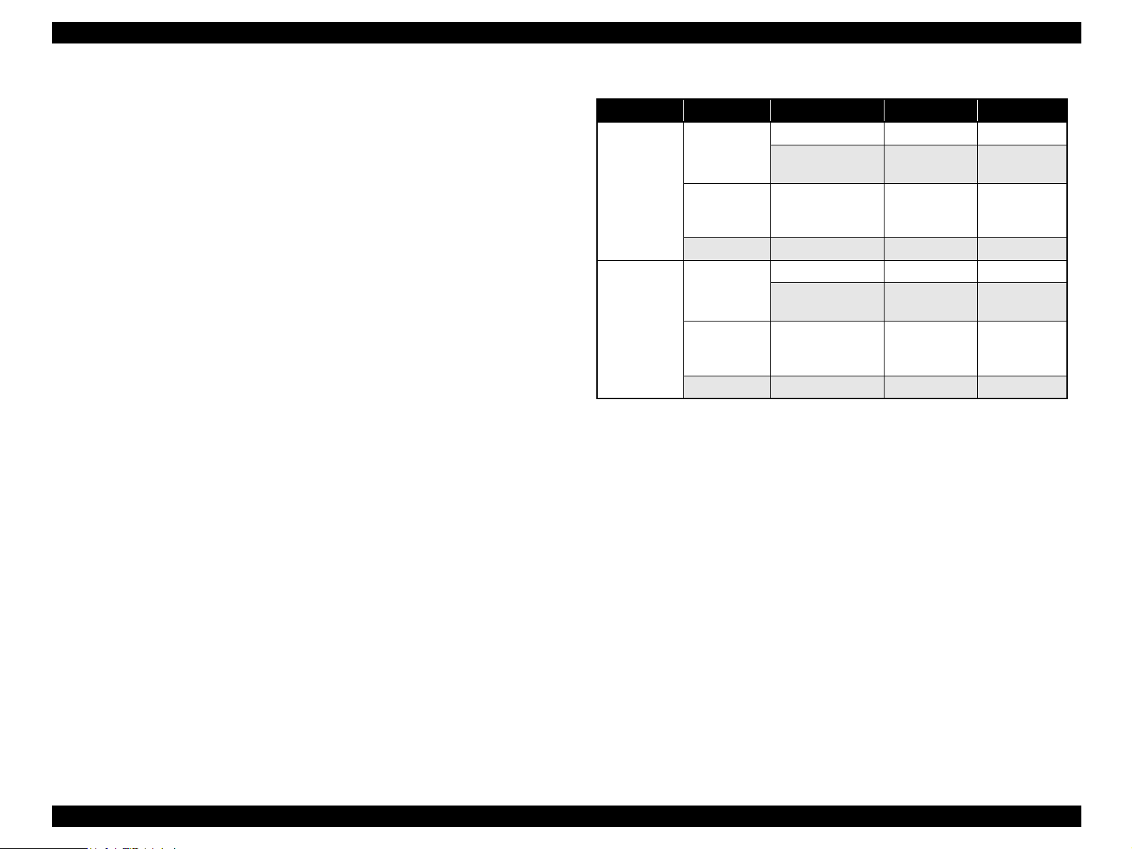
Stand-alone copy functions
It benefits from using a more recently developed type of ink which enables photoquality copies to be made not only on special media but even on plain paper.
Only the basic copy functions are provided for easier operation.
Paper size can be selected from 2, 3 or 4 options.
Table 1-1. Paper Size
Model Paper size
Stylus CX4900/
CX4905/CX5000/
DX5000/DX5050
Stylus CX5900/
CX6000/DX6000/
DX6050
EAI Letter/4”x6”
EURO/ASIA A4/10x15
LATIN Letter/A4/4”x6”
EAI Letter/4”x6”/5”x7”
EURO/ASIA A4/10x15/13x18
LATIN Letter/A4/4”x6”/5”x7”
Paper type can be selected from the following options, which also defines
copy quality.
Model Paper Type
Stylus CX4900/CX4905/CX5000/
DX5000/DX5050
Stylus CX5900/CX6000/DX6000/DX6050 Plain paper/Photo paper/Matte paper
Plain paper/Photo paper
Enlarge / Reduce factor can be selected from two options; actual size (100%)
or “Fit to page”.
Copy margin is automatically selected from three options, related to paper
type and paper size; 3mm, “Small Margins Copy”, or “Border Free Copy”.
Fast and thick draft mode with the combination of real black and composite
black
Copy functions can be directly alternated from memory card print functions,
by operation panel.
Card reader functions
This unit includes memory card slots that support CompactFlash, Memory Stick,
Memory Stick PRO, Micro Drive, SD Memory Card, and xD-Picture Card
standards.
PRODUCT DESCRIPTION Overview 10
Page 11
EPSON Stylus CX4900/CX4905/CX5000/DX5000/DX5050/CX5900/CX6000/DX6000/DX6050 Revision A
Memory card print functions
This unit can print images from the memory card in memory card slots during
stand-alone mode.
The memory card print features are as follows.
Supports “Order sheet printing” whereby images can be selected simply by
marking an index sheet. Selecting images is made easy by checking the
desired images and scanning the index sheet.
Memory card print functions can be directly alternated from copy functions,
by the operation panel.
USB DIRECT-PRINT/PictBridge functions
This unit can print from Digital Still Camera that is compliant with “USB
DIRECT-PRINT”/ “CIPA DC-001-2003 Digital Photo Solutions for Imaging
Devices” and that is connected by USB cable.
Scan functions
This unit provides scan mode so that data can be scanned and transferred to a
connected computer or to e-mail via application software like the EPSON SMART
PANEL.
Photo Print Function (Stylus CX5900/CX6000/DX6000/DX6050 only)
This unit has function to scan and print photos.
Simultaneous use of functions
Printer functions and scanner functions are independent and can therefore be
operated simultaneously from a connected computer.
Easy operation panel
Table 1-2. Operation Panel
Model LED LCD Buttons*
Stylus CX4900/CX4905/CX5000/
DX5000/DX5050
Stylus CX5900/CX6000/DX6000/DX6050 15 LEDs 2.0 inch LCD 13 buttons
Note *1 : Including power button
*2: Including 7 Segment LED
14 LEDs*
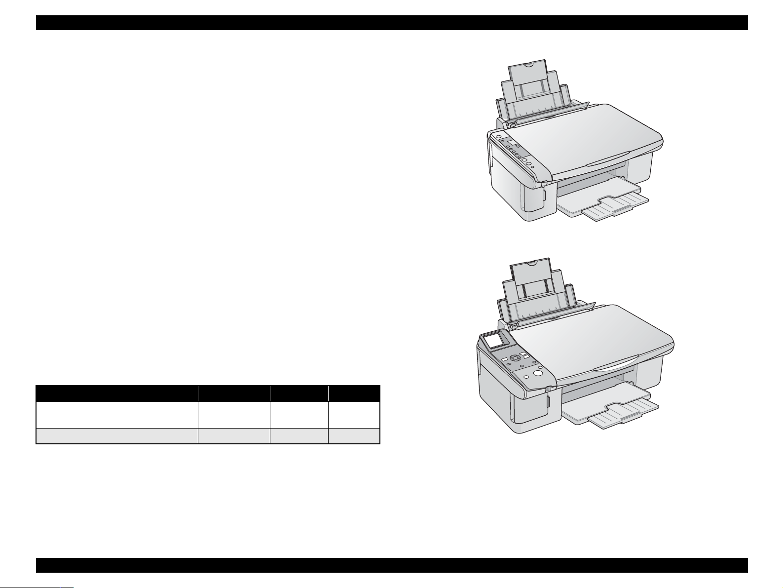
Exterior design
Use of a CIS scanner engine has enabled a more compact design.
Also, this unit has operation panel on the left side, which becomes more distinctive
but still easier to use.
2
--- 10 buttons
Stylus CX4900/CX4905/CX5000/DX5000/DX5050
1
Stylus CX5900/CX6000/DX6000/DX6050
Figure 1-1. External View
PRODUCT DESCRIPTION Overview 11
Page 12
EPSON Stylus CX4900/CX4905/CX5000/DX5000/DX5050/CX5900/CX6000/DX6000/DX6050 Revision A
1.2 Specifications
1.2.1 Printer specifications
This section covers specifications of the printer.
1.2.1.1 Physical Specification
Model Weight (kg)*
Stylus CX4900/CX4905/
CX5000/DX5000/DX5050
Stylus CX5900/CX6000/
DX6000/DX6050
Note *1 : Without ink cartridges
*2: Including rubber feet, excluding loading tray
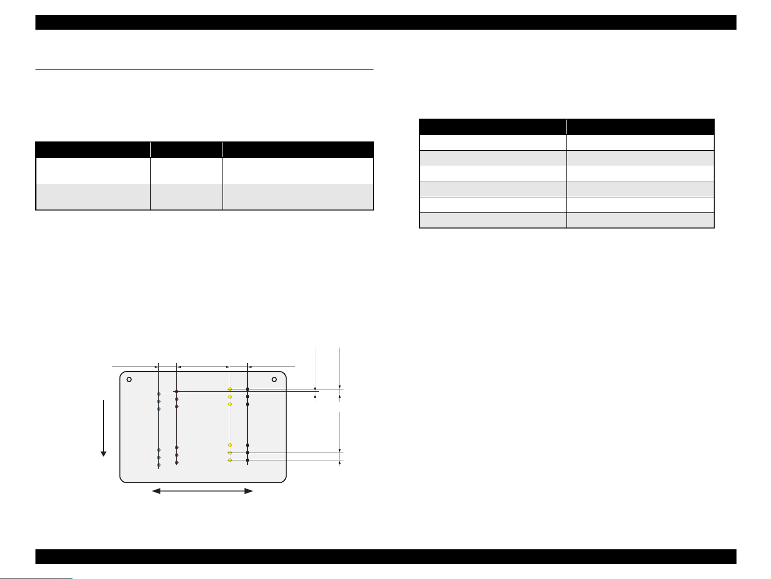
1.2.1.2 Printing Specification
Print Method
On-demand ink jet
Nozzle Configuration
Monochrome 90 nozzles
Color 90 nozzles x 3 (Cyan, Magenta, Yellow)
2.822
(40/360inch)
#A90
#A89
#A88
A row B row C row D row
#A3
Paper Feed Direction
#A2
#A1
Carriage Moving Direction
Figure 1-2. Nozzle configuration
1
6.5
6.9 462.9 (W) x 354.1 (D) x 195.8 (H)
8.467
(120/360inch)
#B90
#C90
#C89
#B89
#C88
#B88
#B3
#B2
#B1
#C3
#C2
#C1
0.07055
(1/360inch)
2
0.1411
(2/360inch)
0.2117
(3/360inch)
Dimension (mm)*
430TBD (W) x 360TBD (D) x 180TBD
(H)
2.822
(40/360inch)
#D90
#D89
#D88
#D3
#D2
#D1
BlackCyan Magenta Yellow
Print Direction
Bi-directional minimum distance printing (with logic seeking)
Print Resolution
Table 1-3. Print Resolution
Horizontal direction (across columns) Vertical direction (paper feed)
360 dpi 120 dpi
360 dpi 360 dpi
360 dpi 720 dpi
720 dpi 720 dpi
1440 dpi 720 dpi
5760 dpi* 1440 dpi*
Note " * " : Those resolution can only be used with the printer driver.
Internal fonts
Character code: Alphanumeric with expanded graphics (PC437)
ASCII, 20H to 7FH only
Fonts: EPSON original fonts
Alphanumeric font: Courier
Input buffer size
64 Kbytes
1.2.1.3 Paper Feed Specifications
Paper feed method
Friction feed, using one ASF (Auto Sheet Feeder)
Paper path
Top feed, front out
Paper feed rates
98.8 mm/sec: High quality mode, 19.05 mm feed
352.8-6.35 mm/sec (13.89-0.25 inch/sec):
High speed mode, continuous feed
PF interval
Programmable in 0.017 mm (1/1440 inch) steps
PRODUCT DESCRIPTION Specifications 12
Page 13
EPSON Stylus CX4900/CX4905/CX5000/DX5000/DX5050/CX5900/CX6000/DX6000/DX6050 Revision A
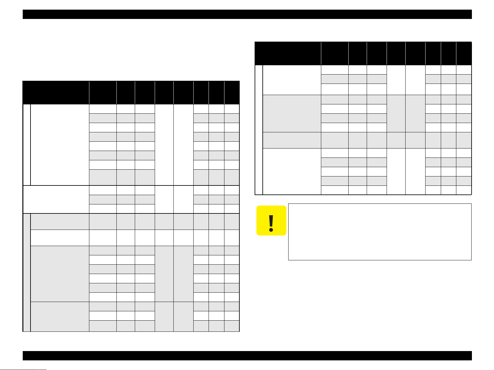
1.2.1.4 Paper Support
Following table shows the paper type and sizes supported by the printer.
Supported paper type and sizes vary depending on the markets and the models.
Table 1-4. Paper Support
Item
Plain paper
Recycled paper
Cut sheets
Envelope
(Bond paper, Air mail, PPC)
Premium Ink Jet Plain
Paper
Bright White Ink Jet
Paper
Premium Photo Paper
Glossy (EAI)
Premium Glossy Photo
Paper (Other)
EPSON special paper
Premium Photo Paper
Semi-Gloss (EAI)
Premium Semigloss
Photo Paper (Other)
Paper
Size
Legal 215.9 355.6
Letter 215.9 279.4 O O O
Half Letter 139.7 215.9 O — —
User
defined
No.10 241.3 104.8
Letter
8" x 10"
5" x 7"
4" x 6"
Letter
4" x 6"
Width
Length
(mm)
A4 210 297 O O O
B5 182 257 — O O
A5 148 210 — O O
A6 105 14 O O O
50.8329
1117.6
DL 220 110 — O O
C6 162 114 — O O
A4
A4
A4
HV
A4
0.11 80 0.11
0.13 92.5 0.13
215.9 279.4
210 297 O O O
203.2 254 O — —
127 178 O O O
101.6 180.6 O O O
101.6 152.4 O O O
215.9 279.4
210 297 — O O
101.6 152.4 O O O
(mm)
127-
Thick-
Weight
ness
(g/m2)
(mm)
0.0864-90
0.11
N/A 75-90
92.5
0.27
0.27
EAI EUR ASIA
80
— O O
— O O
255
250
O O O
O O O
O O O
O — —
O — —
Item
Premium Presentation
Paper Matte (EAI)
Matte PaperHeavyweight (Other)
Photo Paper Glossy
(EAI)
Glossy Photo Paper
(EUR, Asia)
Photo Quality Inkjet
Paper
EPSON special paper
Ultra Premium Photo
Paper Glossy (EAI)
Ultra Glossy Photo
Paper (Other)
C A U T I O N
Make sure that the paper is not wrinkled, fluffed, torn, or
The curve of paper must be 5 mm or below.
When printing onto an envelope, be sure that the flap is on the
Do not use the adhesive envelopes.
Do not use double envelopes and cellophane window envelopes.
Table 1-4. Paper Support
Paper
Size
Letter
8" x 10"
Letter
5" x 7"
4" x 6"
Letter
8" x 10"
5" x 7"
4" x 6"
A4
A4
A4
A4
Width
(mm)
215.9 279.4
210 297 — O O
203.2 254 O — —
215.9 279.4
210 297 O O O
127 178 — O —
101.6 152.4 O O O
210 297 0.12 102 — O O
215.9 279.4
210 297 — O O
203.2 254 O — —
127 178 O O —
101.6 152.4 O O O
folded.
long edge and is folded.
Length
(mm)
Thick-
ness
(mm)
0.23
0.25
0.30
Weight
(g/m2)
167
258
290
EAI EUR ASIA
O — —
O — —
O — —
PRODUCT DESCRIPTION Specifications 13
Page 14
EPSON Stylus CX4900/CX4905/CX5000/DX5000/DX5050/CX5900/CX6000/DX6000/DX6050 Revision A
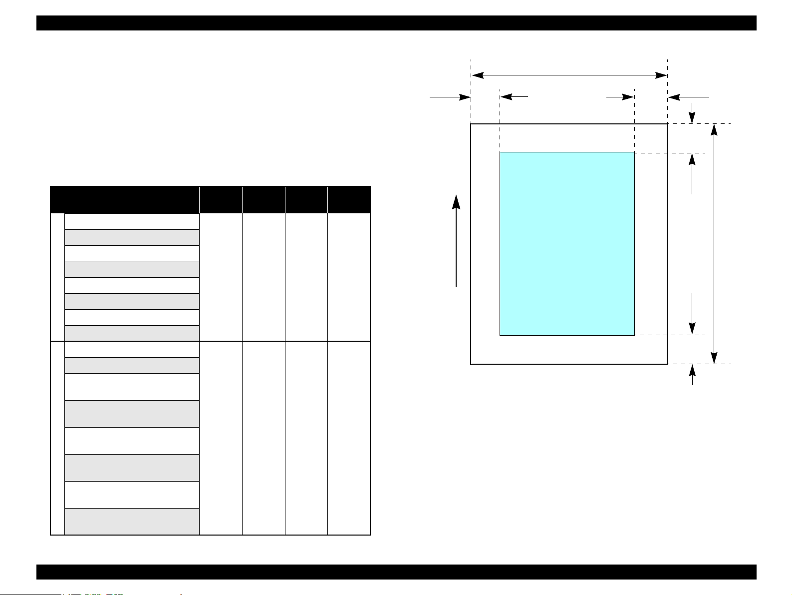
1.2.1.5 Printing Area
Cut sheet (standard printing)
Printable area
The print quality is guaranteed for the print area above the 3 mm bottom
margin. For paper width (PW) and paper length (PL), refer to “1.2.1.4 Paper
Support” (p.13).
Refer to the following table. As for each margin area, refer to Figure 1-3
(p.14).
Table 1-5. Applicable Paper/Printing Area
Paper type
Legal
Letter
A4
B5
A5
Cut sheets
Half Letter
A6
User defined
Premium Ink Jet Plain Paper
Bright White Ink Jet Paper
Premium Photo Paper Glossy
Premium Glossy Photo Paper
Premium Photo Paper Semi-Gloss
Premium Semigloss Photo Paper
Premium Presentation Paper Matte
Matte Paper-Heavyweight
Ultra Glossy Photo Paper
Ultra Premium Glossy Photo Paper
EPSON special paper
Premium Presentation Paper Matte
Matte Paper-Heavyweight
Ultra Premium Photo Paper Glossy
Ultra Glossy Photo Paper
Left
margin
3 mm
(0.12")
3 mm
(0.12")
Right
margin
3 mm
(0.12")
3 mm
(0.12")
Top
margin
3 mm
(0.12")
3 mm
(0.12")
Bottom
margin
3 mm
(0.12")
3 mm
(0.12")
PW
LM
Printable area
Paper Feed Direction
Figure 1-3. Printable Area Cut Sheet (Standard Printing)
RM
TM
PL
BM
PRODUCT DESCRIPTION Specifications 14
Page 15
EPSON Stylus CX4900/CX4905/CX5000/DX5000/DX5050/CX5900/CX6000/DX6000/DX6050 Revision A
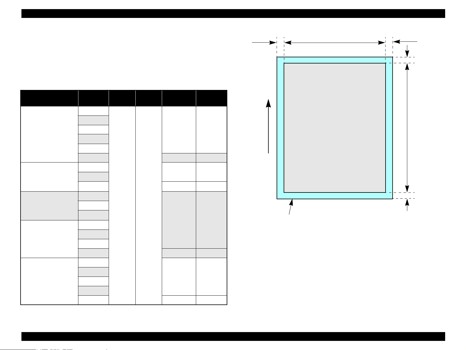
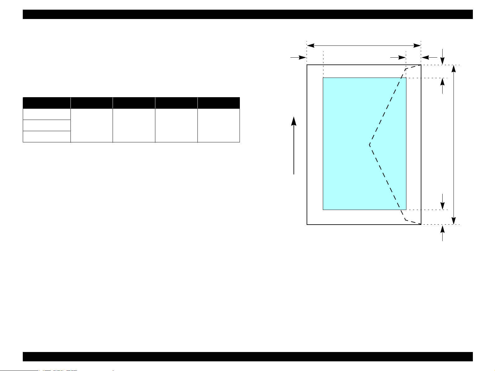
Cut sheet (border-free printing)
Printable area
For paper width (PW) and paper length (PL), refer to “ 1.2.1.4 Paper Support ”
(p.13).
Refer to the following table. As for each overhang area, refer to Figure 1-4
(p.15).
Table 1-6. Applicable Paper/Printing Area (For Printing)
Paper Type Size
Letter
Premium Photo Paper
Glossy (EAI)
Premium Glossy Photo
Paper (Other)
Premium Photo Paper
Semi-Gloss (EAI)
Premium Semigloss
Photo Paper (Other)
Premium Presentation
Paper Matte (EAI) Matte
Paper-Heavyweight
(Other)
Photo Paper Glossy
(EAI)
Glossy Photo Paper
(EUR, Asia)
Ultra Premium Photo
Paper Glossy (EAI)
Ultra Glossy Photo
Paper (Other)
A4
8" x 10"
5" x 7"
HV
4" x 6"
Letter
A4
4" x 6"
Letter
A4
8" x 10"
Letter
A4
5" x 7"
4" x 6"
Letter
A4
8" x 10"
5" x 7"
4" x 6"
LO
(mm)
2.54 2.54
RO
(mm)
TO
(mm)
2.96 4.02
1.34*1/2.82
1.34*1/2.82
1.34*1/2.82
1.34*1/2.82
*22.54
2.96 4.02
*22.54
2.96 4.02
*22.54
2.96 4.02
*22.54
BO
(mm)
*1/3.6*
*1/3.6*
*1/3.6*
*1/3.6*
LO ROPW
TO
Paper size
PL
Paper Feed Direction
2
2
BO
Printable area
Figure 1-4. Printable Area for Cut Sheet (Border-free Printing)
2
2
Note *1 : Stylus CX5900/CX6000/DX6000/DX6050
*2: Stylus CX4900/CX4905/CX5000/DX5000/DX5050
PRODUCT DESCRIPTION Specifications 15
Page 16
EPSON Stylus CX4900/CX4905/CX5000/DX5000/DX5050/CX5900/CX6000/DX6000/DX6050 Revision A
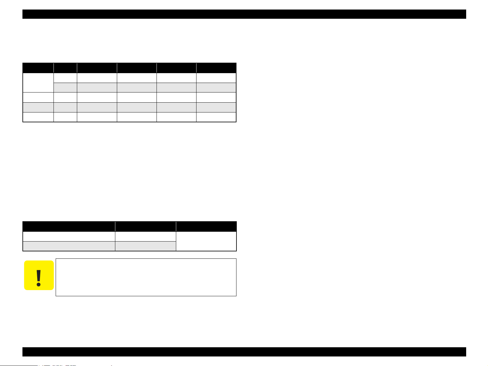
Envelopes
Printable area
For paper width (PW) and paper length (PL), refer to “ 1.2.1.4 Paper Support ”
(p.13).
Refer to the following table. As for each margin area, refer to Figure 1-5
(p.16).
Table 1-7. Applicable Paper/Printing Area
Paper type Left Margin Right Margin Top Margin Bottom Margin
No.10
5mm (0.12") 5mm (0.12") 3mm (0.12") 20mm (0.79")DL
C6
LM
Paper Feed Direction
PL
RM
TM
Printable area
PW
BM
Figure 1-5. Printable Area for Envelopes
PRODUCT DESCRIPTION Specifications 16
Page 17
EPSON Stylus CX4900/CX4905/CX5000/DX5000/DX5050/CX5900/CX6000/DX6000/DX6050 Revision A
1.2.1.6 Ink Cartridge Specification
Type/color: EPSON-brand special ink cartridges
Table 1-8. Ink Cartridge
Color Size Europe ASIA/pacific Latin EAI
Black
Cyan SSS T0712 T0732 T0732 T0692
Magenta SSS T0713 T0733 T0733 T0693
Yellow SSS T0714 T0734 T0734 T0694
Print Capacity (TBD)
Black Ink Cartridge:TBD pages/A4
Color Ink Cartridge:TBD pages/A4 (360x720 dpi, 5% duty for each color)
Shelf life: After packing is opened, it is assumed 6 months, and
Storage Temperature
When stored in individual boxes -30 oC to 40 oC
When installed in main unit -20 oC to 40 oC
S --- --- T0731H T0681
SS T0711 T0731 T0731 T0691
(ISO/IEC10561 Letter Pattern at 360x720 dpi)
380 pages/A4
(360x720 dpi, 5% duty)
assumes 2 years including this.
Table 1-9. Storage Temperature
Situation Storage Temperature Limit
1 month max. at 40 oC
1.2.2 Scanner Specifications
This section covers specifications of the scanner.
1.2.2.1 Basic Specifications
Product type: Flatbed color image scanner
Scanning method: Scanning of fixed document with mobile scan head
Sensor: CIS
Maximum scan area: 8.5" x 11.7" (216 mm x 297 mm)
Document sizes: A4 or US letter
Max. effective pixels: 10,200 x 14,040 pixels (1200 dpi)
Resolution
Main scan: 1200 dpi
Sub scan: 2400 dpi with Micro Step
Scanning resolution: 50 to 4800 dpi (selectable in 1-dpi steps), 7200 dpi,
9600 dpi
Gradations (pixel depth): Each color pixel has 16-bit input and either 1-bit or 8-
bit output.
Scanning speed: 1200 dpi
Color: Approx. 30 msec/line
Monochrome: Approx. 10 msec/line
Light source: RGB Three Color LED
C A U T I O N
Dimension: 12.7mm (W) x 68.0 mm (D) x 47.0 mm (H)
The ink in the ink cartridge freezes when leaving it in the
environment of -16 °C or under. It takes 3 hours that the frozen ink
becomes usable when moving it from the environment of -20 °C to
the environment of 25 °C.
1.2.2.2 Detailed Specifications
Control commands: ESC/I D7
Gamma correction: Two user-defined levels
PRODUCT DESCRIPTION Specifications 17
Page 18
EPSON Stylus CX4900/CX4905/CX5000/DX5000/DX5050/CX5900/CX6000/DX6000/DX6050 Revision A
1.2.2.3 Image Scanning Area
Table 1-10. Image Scanning Area
RW
(readable width)
216 mm (8.5") 1.5 mm ± 1 mm 297 mm (11.7") 1.5 mm ± 1 mm
OLM
(out-of-range left margin)
Original's top left alignment position
First pixel
OLM
Scan direction
RL
(readable length)
(out-of-range top margin)
a
RW
RLOTM
Figure 1-6. Image Scanning Area
OTM
Original
(face down)
Scan bed
Scan area
1.2.3 Common
1.2.3.1 Electric Specification
Primary power input
Table 1-11. Primary Power Input
100-120 V model 220-240 V model
Rated power supply
voltage (ACV)
Input voltage range
(ACV)
Rated current (A)
Rated frequency (Hz) 50 ~ 60
Input frequency range
(Hz)
Standalone
Copying
Low-power Mode
Sleep Mode Approx. 3.5
Power Off Mode Approx. 0.2 Approx. 0.3
Power consumption (W)
Note 1: This product complies with the “Energy Star” standards.
2: If the printer is not operated at all for at least 3 minutes, the standby function reduces
the current to the motor to conserve power.
3: If the scanner is not operated at all for at least 3 minutes (Stylus CX5900/CX6000/
DX6000/DX6050)/4 minutes (Stylus CX4900/CX4905/CX5000/DX5000/DX5050),
the standby function reduces the current to the motor to conserve power.
Approx. 4.0 (Stylus CX4900/CX4905/CX5000/DX5000/DX5050)
Approx. 5.0 (Stylus CX5900/CX6000/DX6000/DX6050)
100 ~ 120 220 ~ 240
90 ~ 132 198 ~ 264
0.4
(max. 0.7)
49.5 ~ 60.5
Approx. 13
(ISO10561 Letter Patter, Plain Paper - Text)
0.2
(max. 0.4)
Insulation resistance
10MΩ minimum (tested between AC line and chassis, test voltage: DC500V)
Dielectric strength
AC1000 Vrms for one minute or AC1200 Vrms for one second
(100-120V version)
AC1500 Vrms for one minute (220-240V version)
PRODUCT DESCRIPTION Specifications 18
Page 19
EPSON Stylus CX4900/CX4905/CX5000/DX5000/DX5050/CX5900/CX6000/DX6000/DX6050 Revision A
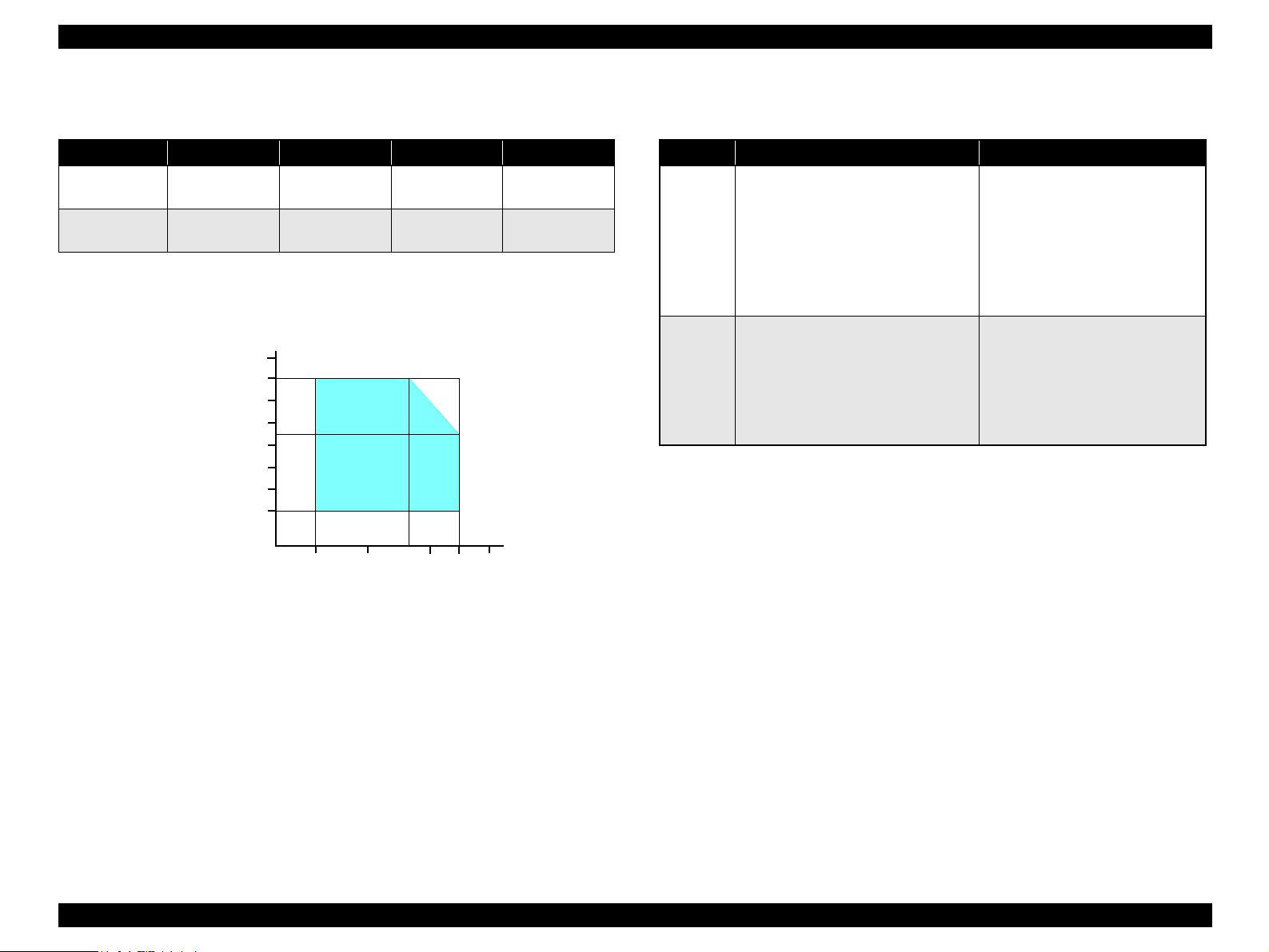
1.2.3.2 Environmental Performance
Table 1-12. Environmental Performance
Condition Temperature Humidity *
80
70
60
50
40
30
20
90
2
20 ~ 80% *
10
Temperature (°C)
Operating 10 ~ 35°C *
Not operating *
Note *1 : No condensation
*2: Under the following conditions
*3: After unpacking (storage)
3
-20 ~ 40°C 5 ~ 85%
Humidity (%)
1
2
1 x 10⁻³ seconds
2 x 10⁻³ seconds
27
20
Impact Vibration
1G,
2G,
35
30
40
0.15G
0.50G
1.2.3.4 Safety Standards: EMC
Table 1-13. Safety Standards: EMC
100-120 V version 220-240 V version
EN 60950, EN60950-1
GOST-R (IEC60950-1, CISPR 22)
Safety
standards
EMC
Note " * " : Stylus CX5900/CX6000/DX6000/DX6050 only
UL60950-1
CNS14336
CSA No.60950-1
CAN/CSA-CEI/IEC CISPR 22 Class B
CNS13438 Class B
FCC Part15 Subpart B Class B
IEC60950-1
K60950-1
NOM-019-SCFI-1998
GB4943*
EN55024
KN61000-4-2/-3/-4/-5/-6/-11
EN55022 Class B
EN61000-3-2, EN61000-3-3
KN22 Class B
AS/NZS CISPR22 Class B *
GB9254 Class B, GB17625.1*
1.2.3.5 Acoustic Noise
Noise level
Approx. 45 dB (according to ISO7779 when for copying)
Figure 1-7. Temperature/Humidity Range
1.2.3.6 CE Marking
220-240 V version
1.2.3.3 Durability
Total print life: 10,000 pages (black only, A4), or five years
(whichever comes first)
Print Head Life: Six billion shots (per nozzle) or five years
(whichever comes first)
Scanner head: MCBF (36,000 cycles)
PRODUCT DESCRIPTION Specifications 19
Low Voltage Directive 73/23/EEC: EN60950
EMC Directive 89/336/EEC: EN55022 Class B
EN61000-3-2
EN61000-3-3
EN55024
Page 20
EPSON Stylus CX4900/CX4905/CX5000/DX5000/DX5050/CX5900/CX6000/DX6000/DX6050 Revision A
1.3 Interface
The EPSON Stylus CX4900/CX4905/CX5000/DX5000/DX5050/CX5900/CX6000/
DX6000/DX6050 provides the following interface.
1.3.1 USB Interface
Standards
“Universal Serial Bus Specifications Revision 2.0”
“Universal Serial Bus Device Class Definition for Printing Devices Version
1.1” (printer unit)
“Universal Serial Bus Mass Storage Class Bulk-Only Transport Revision 1.0”
(storage unit)
Transfer rate: 480 Mbps (High Speed Device)
Data format: NRZI
Compatible connector: USB Series B
Recommended cable length: 2 [m] or less
Device ID
Table 1-14. Device ID
Product
Name
CX4900
CX4905
DX5000
DX5050
Device ID
[00H][5FH]
MFG:EPSON;
CMD:ESCPL2,BDC,D4,D4PX,ESCPR1;
MDL:Stylus[SP] CX4900;
CLS:PRINTER;
DES:EPSON[SP]Stylus[SP] CX4900;
[00H][5FH]
MFG:EPSON;
CMD:ESCPL2,BDC,D4,D4PX,ESCPR1;
MDL:Stylus[SP] DX4900;
CLS:PRINTER;
DES:EPSON[SP]Stylus[SP] DX4900;
[00H][5FH]
MFG:EPSON;
CMD:ESCPL2,BDC,D4,D4PX,ESCPR1;
MDL:Stylus[SP] DX5000;
CLS:PRINTER;
DES:EPSON[SP]Stylus[SP] DX5000;
Product
Name
CX5900
CX6000
DX6000
DX6050
Device ID
[00H][5FH]
MFG:EPSON;
CMD:ESCPL2,BDC,D4,D4PX,ESCPR1;
MDL:Stylus[SP] CX5900;
CLS:PRINTER;
DES:EPSON[SP]Stylus[SP] CX5900;
[00H][5FH]
MFG:EPSON;
CMD:ESCPL2,BDC,D4,D4PX,ESCPR1;
MDL:Stylus[SP] CX6000;
CLS:PRINTER;
DES:EPSON[SP]Stylus[SP] CX6000;
00H][5FH]
MFG:EPSON;
CMD:ESCPL2,BDC,D4,D4PX,ESCPR1;
MDL:Stylus[SP]DX6000;
CLS:PRINTER;
DES:EPSON[SP]Stylus[SP] DX6000;
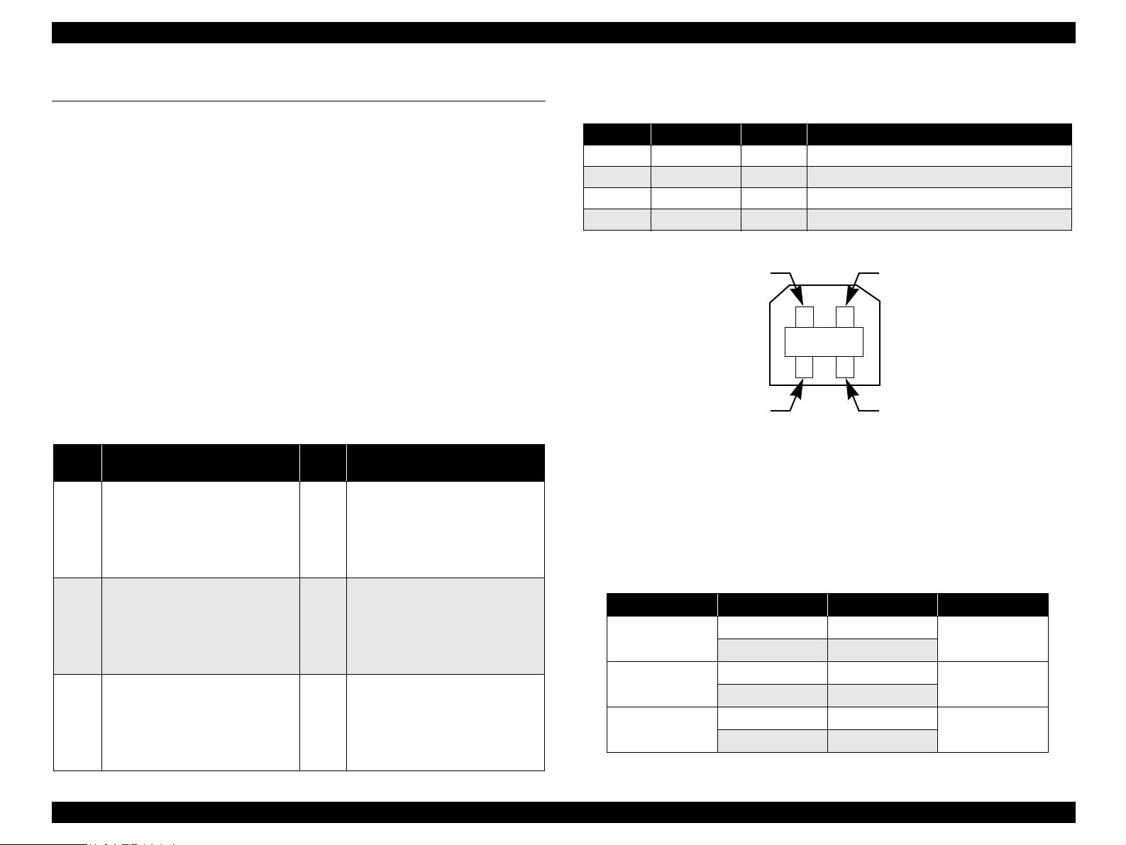
Connector signal layout
Table 1-15. Connector pin assignment and signals
Pin No. Signal name I/O Function description
1 VCC - Cable power. Max. power consumption is 2 mA.
2 -Data Bi-D Data
3 +Data Bi-D Data, pull up to +3.3 V via 1.5 K ohm resistor.
4 Ground - Cable ground
Pin #2
Pin #3
Pin #1
Pin #4
Figure 1-8. USB pin Assignment
Product ID
0x082B (Stylus CX4900/CX4905/CX5000/DX5000/DX5050)
0x082E (Stylus CX5900/CX6000/DX6000/DX6050)
Endpoint attribute
Table 1-16. Endpoint Attribute (Card Slot Model)
I/F No. Endpoint Address Endpoint Type Linked Interface
0x00
0x01
0x02
0x01 Bulk Out
0x02 Bulk In
0x04 Bulk Out
0x05 Bulk In
0x07 Bulk Out
0x08 Bulk In
Scanner
Printer
Card
PRODUCT DESCRIPTION Interface 20
Page 21
EPSON Stylus CX4900/CX4905/CX5000/DX5000/DX5050/CX5900/CX6000/DX6000/DX6050 Revision A
1.3.2 Standard Card Slots
1.3.2.1 Memory Card
Table 1-17. Memory Card
Memory card standards Slots Supported memory cards
Compact Flash CF+ and CompactFlash Specification Revision 3.0 compliant CF Type II slot
Memory Stick/
Memory Stick Duo
Memory Stick PRO/
Memory Stick PRO Duo
SD
MultiMediaCard MultiMediaCard Standard Version 4.1 compliant MultiMediaCard
xD-Picture Card
MemoryStick Standard version 1.42-00 compliant
MemoryStick Standard Memory Stick PRO Format Specifications
version 1.02-00 compliant
Memory Stick/Memory Stick PRO/
SD/MMC/xD-Picture Card slot
SD Memory Card Specifications / PART1. Physical Layer
Specification Version 2.0 compliant
xD-Picture CardTM Card Specification Version 1.20 type M/type H
compliant
• Compact Flash (memory card only)
• Microdrive
• Memory Stick
(maximum capacity: 128 MB, including versions with memory select
function)
• MagicGate Memory Stick (maximum capacity: 128 MB, copy
protection function is not supported)
• Memory Stick Duo (requires Memory Stick Duo adapter)
• MagicGate Memory Stick Duo
• Memory Stick PRO
(copy protection function is not supported)
• Memory Stick PRO Duo (requires Memory Stick Duo adapter)
• SD (Secure Digital) memory card
• miniSD card (requires SD adapter)
• microSD card (requires SD adapter)
• SDHC memory card (except Class support)
• miniSDHC card (requires SD adapter)
• microSDHC (requires SD adapter)
•xD-Picture Card
• xD-Picture Card Type M
• xD-Picture Card Type H
C A U T I O N
Note the following caution points when handling the memory card.
Since the SD card, Memory Stick and xD-Picture Card share the
same slot, only one can be inserted at a time.
When a memory card is being accessed, be sure to keep the
memory card slot's cover closed and do not touch the memory
card.
PRODUCT DESCRIPTION Interface 21
Page 22
EPSON Stylus CX4900/CX4905/CX5000/DX5000/DX5050/CX5900/CX6000/DX6000/DX6050 Revision A
1.3.2.2 Supported Power Supply Voltage
3.3 V/ 5 V (both)
3.3 V (only)
NOTE 1: 3.3 V power is supplied to media that support both 3.3 V and 5 V.
2: Maximum current to memory card is 500 mA.
3: 5V type memory cards are not supported.
1.3.2.3 Multi-slot Operations
Overview
There is only one type of card that can be used to simultaneously access both
a connected computer and the direct printing function.
The slots have assigned priority to determine which slot will be accessed first
when cards are inserted in several slots at once.
To select a card that has been inserted in a non-active slot, the card in the
active slot must first be removed.
Only the image files in the active slot are valid and
Direct printing
Connection to computer
(Windows)
Connection to computer
(Macintosh)
Details
have assigned frame numbers. The number of images
will not change if a card is also inserted in a nonselected slot.
Only one drive is displayed at a time as a “removable
disk” and only the card that is in the active slot can be
accessed via the removable disk. A card that has been
inserted into a non-selected slot cannot be accessed.
Only the card in the active slot can be mounted on the
desktop. A card that has been inserted into a nonselected slot cannot be mounted on the desktop.
Access priority
The access priority among slots is assigned as:
1: Memory Stick (Memory Stick PRO)/SD (MMC)/xD-Picture Card
2: CF (Micro Drive)
Slot selection when power is turned on
If cards are inserted in several slots when the power is turned on, the active
slot is determined by the priority ranks listed above.
Example: If CF and Memory Stick are both inserted at power-on, the xD-
Picture Card slot becomes the active slot.
Slot selection after power is turned on
When a card is removed from the active slot, the slot with the next-highest
priority becomes the active slot (if a card has been inserted into it). There is no
need to re-insert any card before accessing it.
PRODUCT DESCRIPTION Interface 22
Page 23
EPSON Stylus CX4900/CX4905/CX5000/DX5000/DX5050/CX5900/CX6000/DX6000/DX6050 Revision A
1.4 Stand-alone Copy
1.4.1 Basic Specifications
1.4.1.1 Supported Paper Sizes, Types and Qualities
Table 1-18. Supported Paper Sizes, Types and Qualities (for EAI)
Paper type
1
Paper name
Panel
indication
Quality *
Plain Paper
Plain Paper Plain Paper Letter/A4Recycled Paper
Bright White Paper
Premium Photo Paper Glossy *
Premium Photo Paper Semi-gloss*
Photo Paper Glossy*2*
2
3
Photo Paper Photo Paper
2
Photo Paper Photo Paper
Photo Paper Photo Paper
Ultra Premium Photo Paper Glossy*2Photo Paper Photo Paper
Ultra Premium Photo Paper Luster*2*4Photo Paper Photo Paper Letter/A4
Premium Presentation Paper Matte*5Matte Paper Matte Paper Letter/A4
Note : Letter/A4: Selectable by Setup mode only for Latin region.
Note *1 : The quality of draft copy is not affected by “Paper type” selection.
*2: For photo paper: Printing parameter is same as Premium Glossy Photo Paper.
*3: Printing is available, but Color tone is not secured.
*4: Stylus CX4900/CX4905/CX5000/DX5000/DX5050 only
*5: Stylus CX5900/CX6000/DX6000/DX6050 only
Paper size
Paper
size
Letter/A4
5" x 7"
4" x 6"
Letter/A4
4" x 6"
Letter/A4
4" x 6"
Letter/A4
5" x 7"
4" x 6"
Panel
indication
Table 1-19. Supported Paper Sizes, Types and Qualities (for EUR/ASIA)
Paper type
1
Paper name
Panel
indication
Quality *
Plain Paper
Plain Paper Plain Paper A4 A4Recycled Paper
Bright White Paper
Premium Glossy Photo Paper *
Premium Semigloss Photo
2
Paper*
Glossy Photo Paper*2*
3
Ultra Glossy Photo Paper*
Matte Paper Heavyweight*
2
Photo Paper Photo PaperA413 x 18
Photo Paper Photo Paper
Photo Paper Photo PaperA413 x 18
2
6
Photo Paper Photo Paper
Matte Paper Matte Paper A4 A4
Note *1 : The quality of draft copy is not affected by “Paper type” selection.
*2: For photo paper: Printing parameter is same as Premium Glossy Photo Paper.
*3: Printing is available, but Color tone is not secured.
*4: 13 x 18: The panel indicator only. 13 x 18 is the same size as 5” x 7”
*5: 10 x 15: The panel indicator only. 10 x 15 is the same size as 4” x 6”
*6: Stylus CX5900/CX6000/DX6000/DX6050 only
Paper size
Paper
size
Panel indication
A4
13 x 18/5” x 7”*
10 x 15
10 x 15/4” x 6”*
A4
10 x 15A410 x 15/4” x 6”*
A4
13 x 18/5” x 7”*
A4
10 x 15/4” x 6”*
A4
13 x 18/5” x 7”*
10 x 15/4” x 6”*
10 x 15
13 x 18
10 x 15
1.4.1.2 Zoom Function
The zoom function provides enlarged or reduced copies of originals. The either of the
following can be selected from the operation panel.
Actual (The state which “Fit to page” is not selected. It is the power-on default.)
The zoom factor is set to 100%.
Fit to page
This function detects the image size of the original and automatically sets the
zoom factor of the copy according to the copy paper's printable area.
4
5
5
4
5
4
5
PRODUCT DESCRIPTION Stand-alone Copy 23
Page 24
EPSON Stylus CX4900/CX4905/CX5000/DX5000/DX5050/CX5900/CX6000/DX6000/DX6050 Revision A
1.4.1.3 Number of Copies Setting
This function sets the number of copies. The setting range is:
• 1 to 9 and 100 (Stylus CX4900/CX4905/CX5000/DX5000/DX5050)
• 1 to 99 (Stylus CX5900/CX6000/DX6000/DX6050)
1.4.1.4 Maximum Copy Size
216 mm x 297 mm
1.4.1.5 Copy Layout
The following copy layout is provided according to “Paper type”, “Paper size” and
zoom selections.
Standard copy
Provided for ordinary use with 3mm copy margin from every side.
BorderFree copy
Border-free printing of copies occurs when the print area is set as larger than the
copy paper's size. In such cases, the outer edges of the original image may be
omitted in the printed copy.
Small Margins copy
This function sets a 1.5mm margin on all four sides when printing in order to make
maximum use of the original image and copy paper.
NOTE: Only “Standard Copy” can be used in draft copy mode.
Table 1-20. Copy Layout
Zoom Paper type Paper size B&W / Color Layout
A4, Letter/A4* B&W, Color Standard
Plain Paper
1
Actual*
Photo Paper
Matte Paper*4A4, Letter/A4* B&W, Color Small margin
Plain Paper
Fit to Page*
Note : Letter/A4: Selectable by Setup mode only for Latin region.
Note *1: Actual is the state that “Fit to page” is not selected.
*2: For EAI models
*3: For EUR/Asia/Pacific models
*4: Stylus CX5900/CX6000/DX6000/DX6050 only
*5: “Fit to page” automatically sets the enlarge/reduce scale so that the entire image fits
6
Photo Paper
Matte Paper*
into the printable area or the border free area when border free layout is selected.
When the original image is smaller than general card size (approx. 54mm x 86mm),
the print margins will be different from the one that is defined by each layout.
The image placement uses the upper left corner as the origin and any margins that
occur during the fitting process occur along the bottom and/or right edge.
4" x 6" (10 x 15),
5" x 7" (13 x 18)
Letter*2/A4*3,
4" x 6" (10 x 15),
5" x 7" (13 x 18)
A4, Letter/A4* B&W, Color Standard
4" x 6" (10 x 15),
5" x 7" (13 x 18)
Letter*2/A4*3,
4" x 6" (10 x 15),
5" x 7" (13 x 18)
4
Letter*2/A4*
B&W, Color Standard
B&W, Color Small margin
B&W, Color Standard
B&W, Color Border free
3
B&W, Color Border free
PRODUCT DESCRIPTION Stand-alone Copy 24
Page 25
EPSON Stylus CX4900/CX4905/CX5000/DX5000/DX5050/CX5900/CX6000/DX6000/DX6050 Revision A
1.4.1.6 Multiple Copies From an Original
Second and subsequent copies can be printed from an original without scanning.
When printing two or more copies, under the following settings the scanned data can
be stored in the unit's memory so that the second and subsequent copies can be printed
without scanning.
“Draft” mode (monochrome/color)
“Text” mode (monochrome)
1.4.2 Copy Speed (TBD)
1.4.2.1 Black Copy Speed
Plain Paper – Draft 13.4 cpm (Copy per minute), Plain Paper – 3.0 cpm
Black e-Memo text A4 size pattern, zoom 100%
The above speed is for the second and subsequent copies (the time between
ejection of the first page to ejection of the second page).
1.4.2.2 Color Copy Speed
Plain Paper – Draft 13.4 cpm (Copy per minute), Plain Paper –1.0 cpm
Color e-Memo text A4 size pattern, zoom 100%
The above speed is for the second and subsequent copies (the time between
ejection of the first page to ejection of the second page)
1.4.3 Configuration for copying
Table 1-21. Configuration for Copying
Copy Mode setting Scan and Print configuration
Enlarge /
1
Reduce*
100 (Default) 360 x 360 VSD4 Off On
100 (Default) 360 x 720 VSD1 On On
100 (Default) 720 x 720*
100 (Default) 720 x 720*
100 (Default) 1440 x 720 VSD3 On On
100 (Default) 1440 x 720 VSD3 On On
(%)
Paper type
Draft*2
(Plain paper
only)
Plain Paper
Photo Paper
Matte Paper*
B&W /
Color
B&W 100 (Default) 360 x 120 Eco Off On
Color 100 (Default) 360 x 120 Eco Off On
*3
B&W
*3
Color
*3
B&W
*3
Color
B&W 100 (Default) 1440 x 720 VSD3 On On
Color 100 (Default) 1440 x 720 VSD3 On On
*3
B&W
4
Color
*3
Note *1 : “Default” is the state in which “Fit to page” is not selected. When “Fit to page” is
selected, scan resolution will be optimized according to enlarge/reduce scale.
*2: When printing in draft mode, both real black and composite black will be used for
black printing.
*3: Pure black will be used in both B&W and color mode.
*4: Stylus CX5900/CX6000/DX6000/DX6050 only
Print
resolution
(H x V dpi)
4
4
Dot size MW
VSD3 On On
VSD3 On On
Speed
High
PRODUCT DESCRIPTION Stand-alone Copy 25
Page 26
EPSON Stylus CX4900/CX4905/CX5000/DX5000/DX5050/CX5900/CX6000/DX6000/DX6050 Revision A
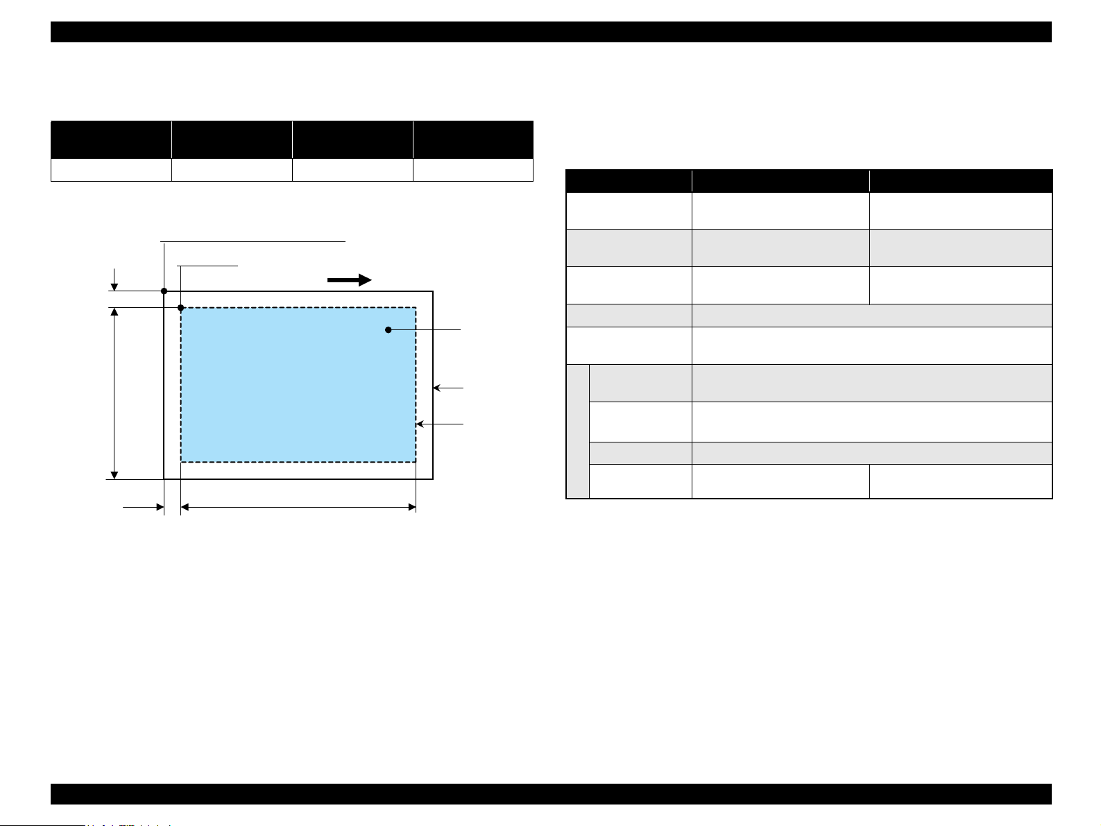
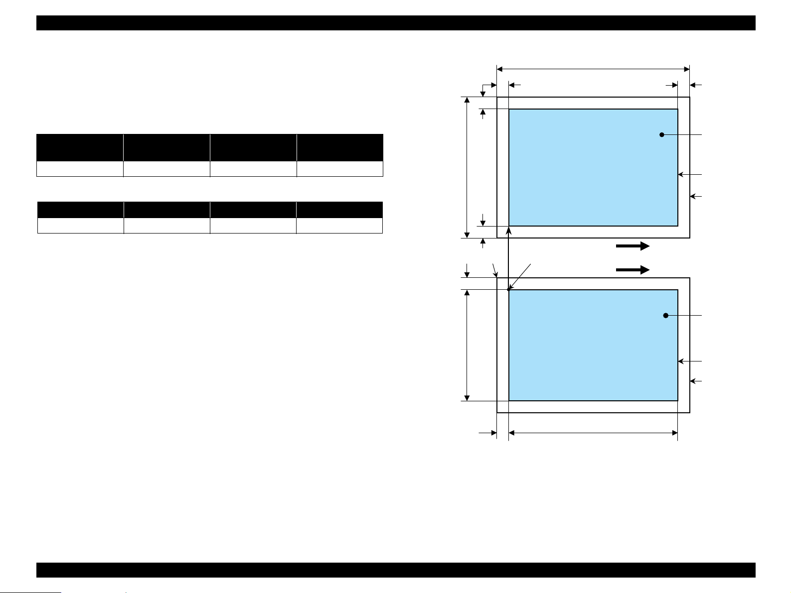
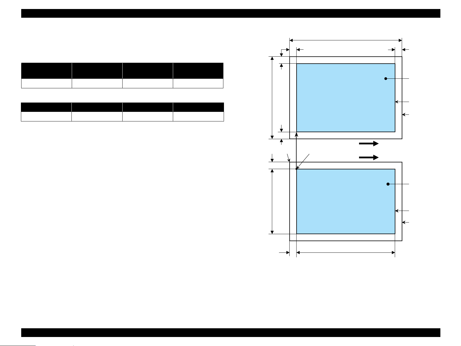
1.4.4 Relation between Original and Copy
1.4.4.1 Standard Copy
The following table shows the relative positioning of the original and copy.
Table 1-22. Original (scanner)
RW
(readable width)
216 mm (8.5") 3 mm 297 mm (11.7") 3 mm
RM LM TM BM
3 mm (0.12") 3 mm (0.12") 3 mm (0.12") 3 mm (0.12")
Note : Refer to “ 1.2.1.4 Paper Support” (p.13) for paper width (PW) and paper length (PL).
(out-of-range left margin)
OLM
Table 1-23. Copy (printer)
RL
(readable length)
OTM
(out-of-range top margin)
OLM
RM
TopPW
LM
TopRW
*2*1
PL
Right side of copy
Print direction
Scan direction
BMTM
a
a
Copy
Print area
Copy paper
Original
(face down)
Scan area
Scan bed
Right side of original
OTM RL
Note *1 : This indicates the top left corner of the original. Normally, this corner is aligned
with the scan bed's top right corner as the reference point.
*2: This indicates the scan start position at the top left of the original, which
corresponds to the print start position at the top left of the copy. The bottom right
corner position of the copy is within the print area but varies according to the
enlarge/reduce setting.
Figure 1-9. Standard Copy
PRODUCT DESCRIPTION Stand-alone Copy 26
Page 27
EPSON Stylus CX4900/CX4905/CX5000/DX5000/DX5050/CX5900/CX6000/DX6000/DX6050 Revision A
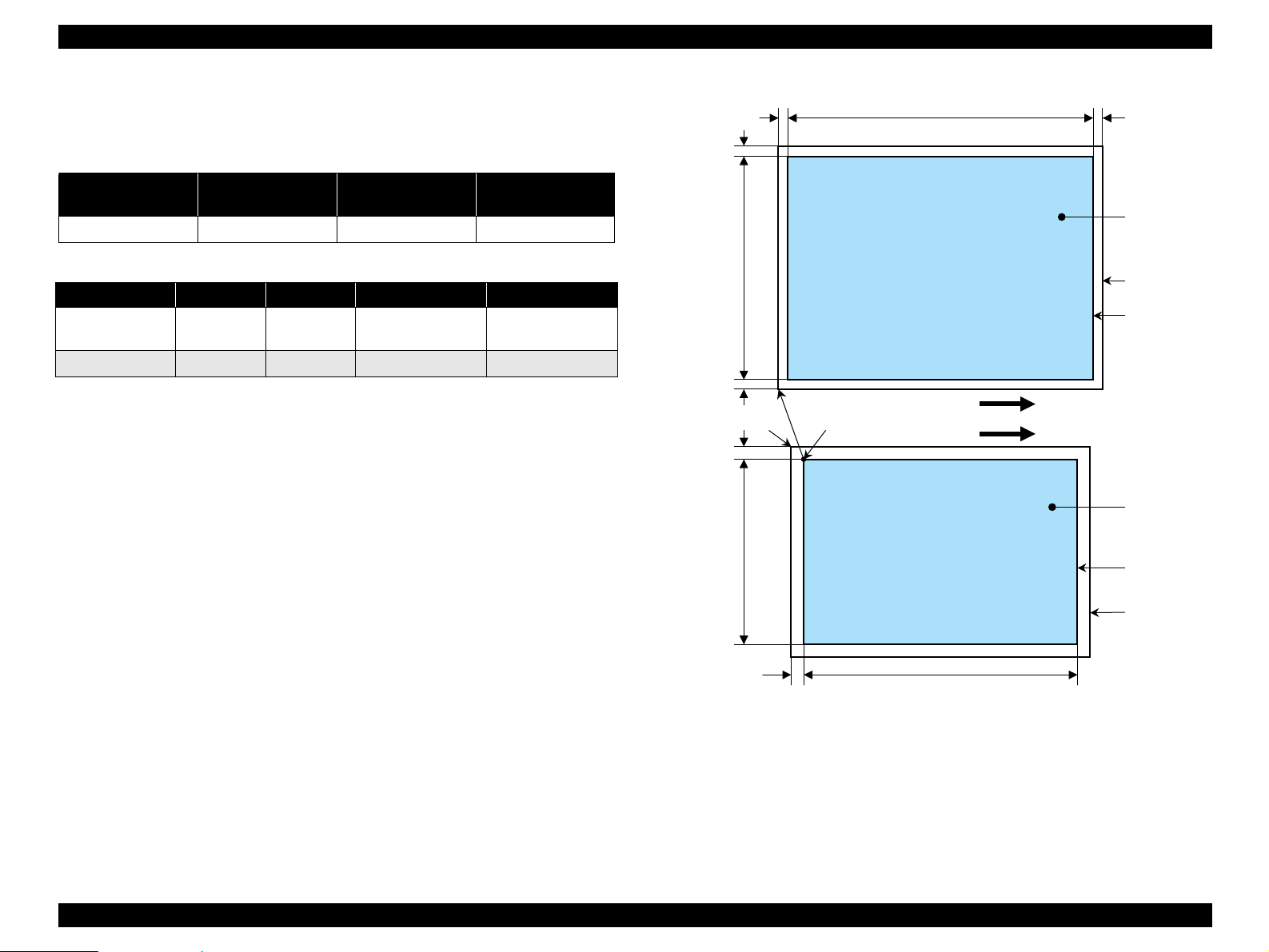
1.4.4.2 BorderFree Copy
The following table shows the relative positioning of the original and copy.
Table 1-24. Original (scanner)
RW
(readable width)
216 mm (8.5") 1.5 mm ± 1 mm 297 mm (11.7") 1.5 mm ± 1 mm
Paper size RO LO TO BO
4" x 6"
Other 2.54 mm 2.54 mm 2.96 mm 4.02 mm
Note : Refer to “ 1.2.1.4 Paper Support” (p.13) for paper width (PW) and paper length (PL).
Note *1 : Stylus CX5900/CX6000/DX6000/DX6050
*2: Stylus CX4900/CX4905/CX5000/DX5000/DX5050
(out-of-range left margin)
2.54 mm 2.54 mm
OLM
Table 1-25. Copy (printer)
RL
(readable length)
1.34 mm*1/
2.82 mm*
OTM
(out-of-range top margin)
2
2.54 mm*1/
3.6 mm*
2
LO
OLM
TO
PL
Right side of copy
TopPW
a
Print direction
*2*1
Scan direction
a
TopRW
BO
Copy
Print area
Copy paper
Original
(face down)
Scan area
Scan bed
Right side of original
OTM RL
Note *1 : This indicates the top left corner of the original. Normally, this corner is aligned
with the scan bed's top right corner as the reference point.
*2: This indicates the scan start position at the top left of the original, which
corresponds to the print start position at the top left of the copy. The bottom right
corner position of the copy is within the print area but varies according to the
enlarge/reduce setting.
Figure 1-10. BorderFree Copy
PRODUCT DESCRIPTION Stand-alone Copy 27
Page 28
EPSON Stylus CX4900/CX4905/CX5000/DX5000/DX5050/CX5900/CX6000/DX6000/DX6050 Revision A
1.4.4.3 Small Margins copy
The following table shows the relative positioning of the original and copy.
Table 1-26. Original (scanner)
RW
(readable width)
216 mm (8.5") 1.5 mm ± 1 mm 297 mm (11.7") 1.5 mm ± 1 mm
RM LM TM BM
1.5 mm 1.5 mm 1.5 mm 1.5 mm
Note : Refer to “ 1.2.1.4 Paper Support” (p.13) for paper width (PW) and paper length (PL).
(out-of-range left margin)
OLM
Table 1-27. Copy (printer)
RL
(readable length)
OTM
(out-of-range top margin)
OLM
RM
TopPW
LM
TopRW
*2*1
PL
Right side of copy
Print direction
Scan direction
BMTM
a
a
Copy
Print area
Copy paper
Original
(face down)
Scan area
Scan bed
Right side of original
OTM RL
Note *1 : This indicates the top left corner of the original. Normally, this corner is aligned
with the scan bed's top right corner as the reference point.
*2: This indicates the scan start position at the top left of the original, which
corresponds to the print start position at the top left of the copy. The bottom right
corner position of the copy is within the print area but varies according to the
enlarge/reduce setting.
Figure 1-11. Small Margins copy
PRODUCT DESCRIPTION Stand-alone Copy 28
Page 29

EPSON Stylus CX4900/CX4905/CX5000/DX5000/DX5050/CX5900/CX6000/DX6000/DX6050 Revision A
1.5 Memory Card Print
1.5.1 Basic Specifications
1.5.1.1 File System
DCF Version 1.0 or 2.0 is the file system that can be used with this unit's stand-alone
printing functions. Operation is not guaranteed when any other file system is used.
The file system used by the card reader function depends on the host's specifications.
For a detailed description of the DCF specifications, see “Design Rule for Camera File
System Standard, DCF Version 2.0, JEIDA-CP-3461”.
1.5.1.2 Media Format
Media must be formatted according to the DCF Version 1.0 or 2.0 standard.
DOS FAT formats (FAT12, FAT16, FAT32*1) and single partition (basic
partition)
Note *1 : Only the card to which use is permitted by each memory card standard
1.5.1.3 File Formats
The file formats supported by this unit are described below.
JPEG files (*.JPG)
These are photo data files that comply with the Exif Version 2.21. (Extif version
1.0/2.0/2.1/2.2/2.21)
Camera specification files (*.MRK)
These are definition files used when in camera specification mode. An
“AUTOPRINT.MRK” file whose full path name is no longer than 32 characters is
valid.
PRINT Image Framer (P.I.F.) definition file (*.USD)
(Stylus CX5900/CX6000/DX6000/DX6050 only)
File to define the layout in accordance with the PRINT Image Framer
specifications. Files only in the “
with Print Image Framer Rev.2.1.
¥\EPUDL\¥” directory are available. Compatible
C H E C K
P O I N T
However, any file that is saved in the following directories or their
sub-directories cannot be included as files to be printed.
Directories containing system properties or hidden properties
Directories that contain any double-byte characters in the
directory name
“RECYCLED”: Windows directory for deleted files
“PREVIEW”: Directories containing CASIO's DSC
thumbnail images
“SCENE”: Directories containing data for CASIO's DSC
Best Shot function
“MSSONY”: Directories containing SONY's DSC e-mail
image data, voice memos, video files, or noncompressed images
“DCIM¥ALBUM¥IMAGE”: Directories containing CASIO's
DSC album data save directory.
1.5.1.4 Valid Image Size
The maximum image size handled by this unit is:
Horizontal: 80 X 9200 (pixels)
Vertical: 80 Y 9200 (pixels)
1.5.1.5 Maximum Number of Photo Data Files
This unit can handle up to 999 photo data files. If the amount of photo data to be
recorded exceeds the capacity of one memory card, this unit uses file sorting rules to
sort the photo data into valid photo data in frames numbered from 1 to 999. Although it
is possible to print photo data files with frame numbers over 999 that have been
specified for printing by camera specification files, the maximum number of frames
that can be specified is 999 frames.
If you insert a memory card that contains over 999 photo data files, only files up to 999
will be printed by the “Print All” or “Print index sheet” functions.
1.5.1.6 Thumbnail Image Data
This unit handles thumbnail image data in the DCF Version 1.0 or 2.0 format
(Exif format, 160 x 120 pixels).
During this unit's Index sheet and memory card printing modes, the layout is 80
thumbnails per sheet (when using plain paper or special paper in high-speed print
mode).
PRODUCT DESCRIPTION Memory Card Print 29
Page 30
EPSON Stylus CX4900/CX4905/CX5000/DX5000/DX5050/CX5900/CX6000/DX6000/DX6050 Revision A
1.5.1.7 File Sorting
This unit stores all photo data files in the memory, using the photo data files' full-path
file names (for example, “
¥DCIM¥100EPSON¥EPSN0000.JPG”), and assigned photo
frame numbers. Since photo frame numbers are assigned based on this unit's own
proprietary file sorting rules, the assigned frame numbers do not necessarily match
those indicated by digital cameras.
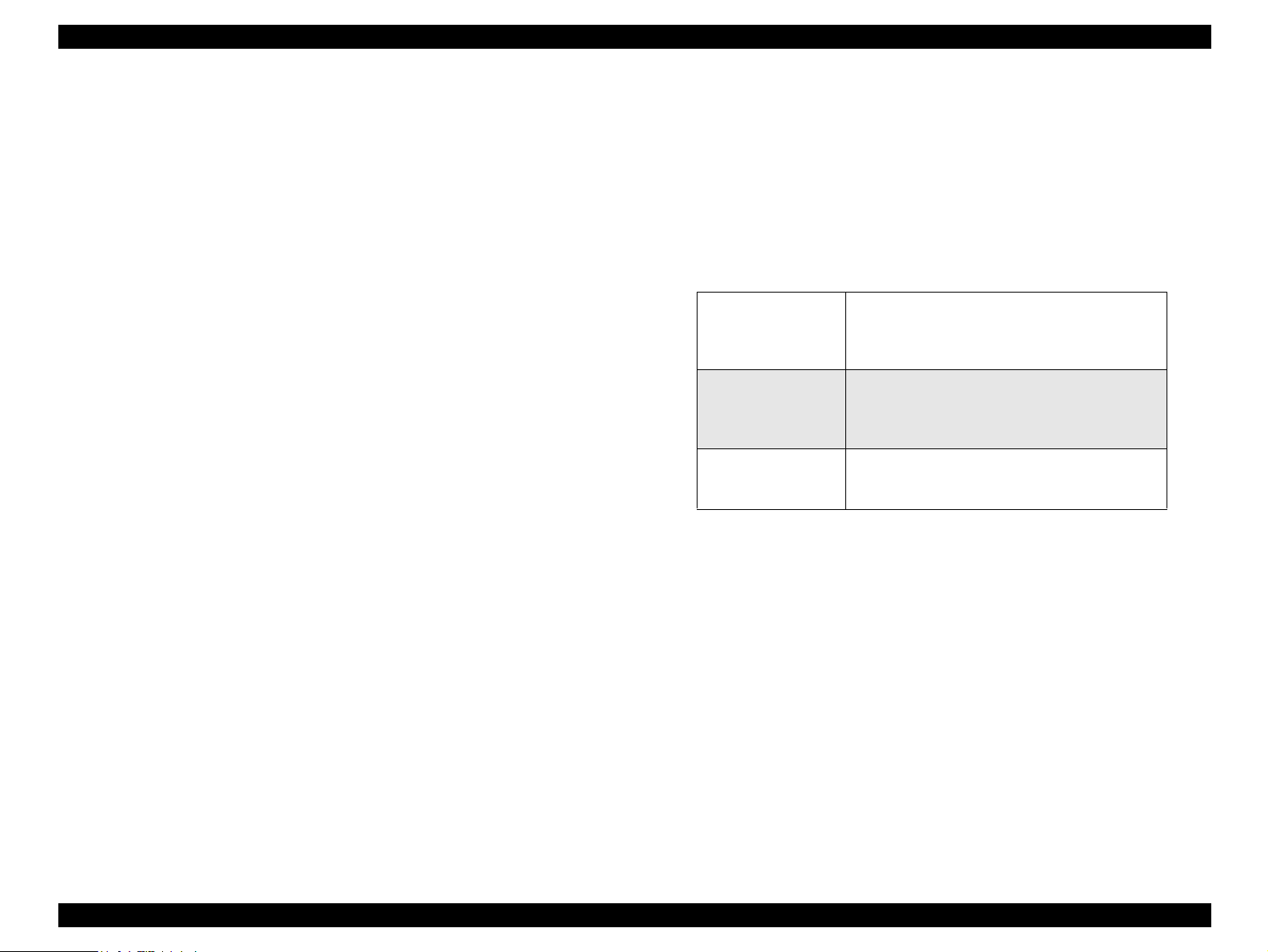
1.5.1.8 File Sorting Rules
This unit sorts photo data files based on the following prioritization rule.
File name is sorted in ASCII order as full path name.
NOTE: Sorting results are not guaranteed if two files have matching full-path file
names. (Matching full-path file names are not allowed under the DOS
specification.)
1.5.1.9 Rules for Acquisition of Date/Time Data
The following priorities are used to fetch date and time information from photo data
files.
1. Date/time data that complies with the standard format (Exif) for digital
cameras
2. Date/time data that complies with the DOS standard file system (file time
stamps)
3. Fixed values (01/01/1980, 00:00:00)
Note that the date/time data assigned to individual photo data files does not necessarily
match the date/time when the photo was actually taken. The photo date/time may be
modified due to the digital camera's calendar settings (presence/absence of functions,
incorrect date/time settings, etc.), processing of the photo data after the photo was
taken, or subsequent saving of data. In such cases, this unit performs the relevant
processing based on the most recently modified date/time data.
1.5.1.10 Number of Sheets which can be Printed in Total
Printing sum total number of sheets presupposes that it is possible to 999 sheets.
Moreover, the printing sum total number of sheets per sheet is possible to 99 sheets.
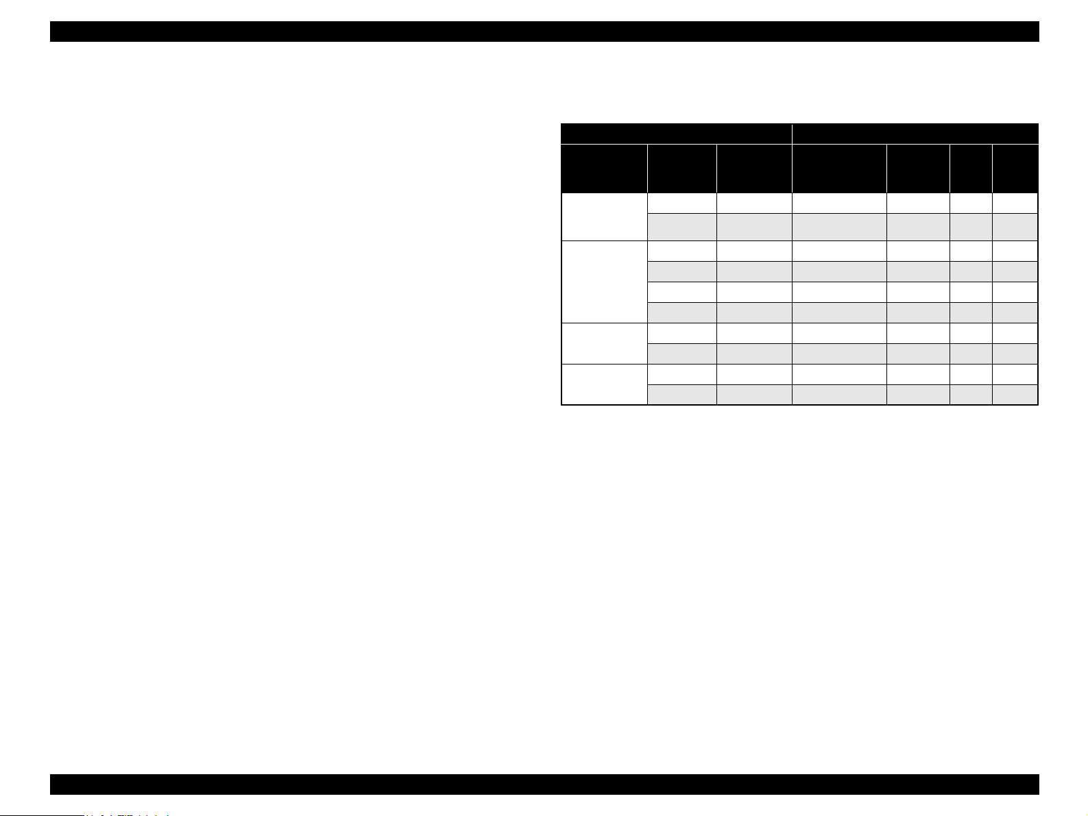
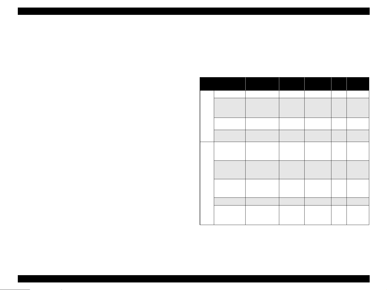
1.5.2 Functions
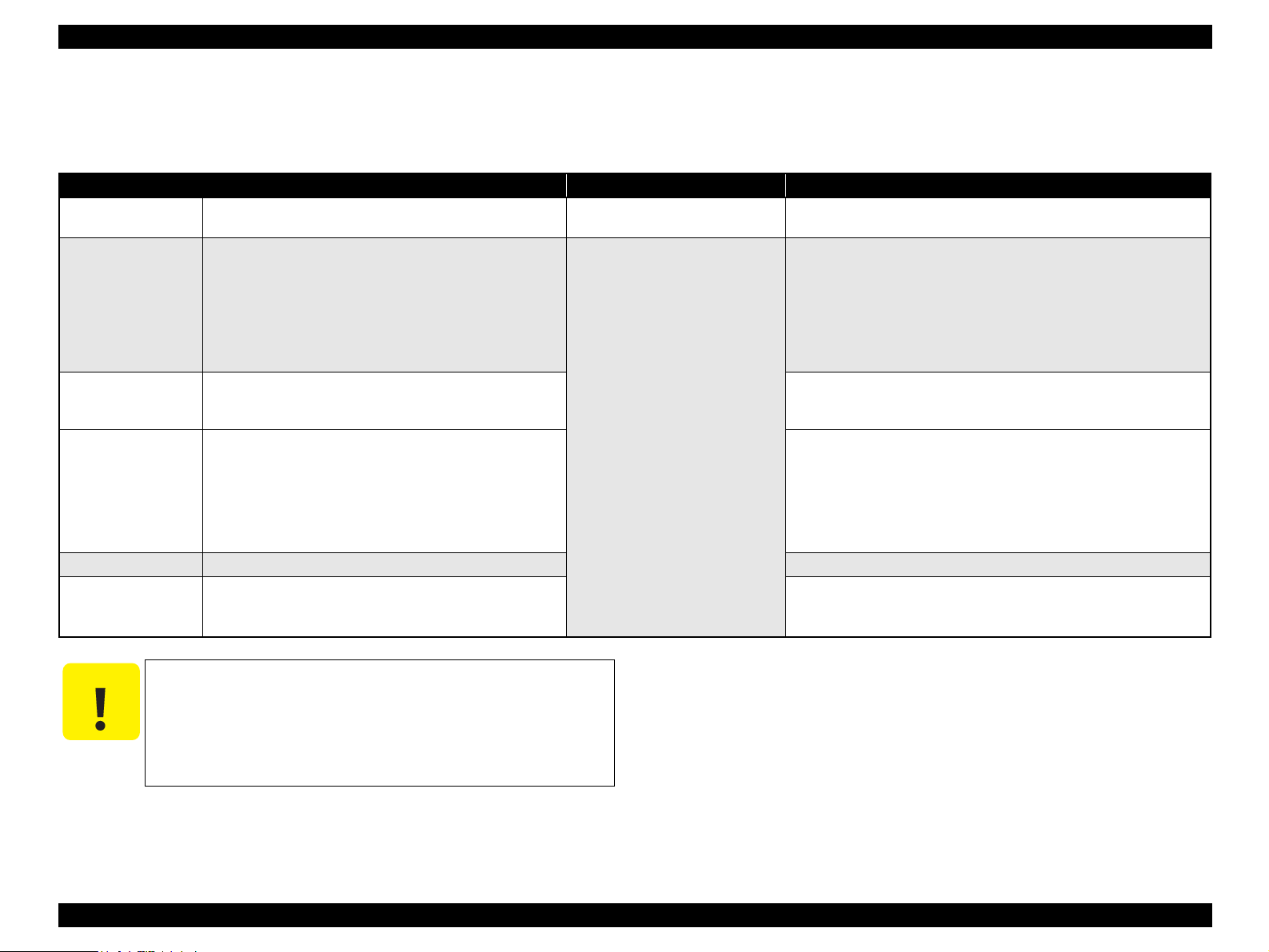
1.5.2.1 List of Functions
The memory card print menu and its settings are listed in the following table. The
values shown in this table indicate the total number of options and the number of pages
or copies that can be printed consecutively.
Table 1-28. List of Functions
Memory card printing Mode selection Layout Paper type
Print index sheet Print Index Sheet None Plain Paper 1 1
1
Print from index
sheet
Print all images Print All / DPOF
CX5000/CX5050*
DPOF * Print All / DPOF
Stylus CX4900/CX4905/
Print selected
image
2
Print all images
DPOF * Print All / DPOF
DX6000/DX6050*
Print index sheet Print Index Sheet None Plain Paper 1 1
Stylus CX5900/CX6000/
Print from index
sheet
Note " * " : It is available only DPOF file exists in the memory card.
Note *1: “Print Index Sheet” will be selected as default function of Memory Card Print. But
when DPOF file exists in the memory card, “Print All / DPOF” will be selected as
default and DPOF print can be done easily.
*2: “Print Select” will be selected as default function of Memory Card Print.
Print From Index
Sheet
Print Select
Print All /
PictBridge
Print From Index
Sheet
• Standard
• Border free
• Standard
• Border free
• Standard
• Border free
• Standard
• Border free
• Border free
• Standard
• Border free
• Border free
• Standard
• Border free
• Border free
• Standard
• Border free
• Border free
• Plain Paper
• Photo Paper
• Plain Paper
• Photo Paper
• Plain Paper
• Photo Paper
• Plain Paper
• Photo Paper
• Matte Paper
• Plain Paper
• Photo Paper
• Matte Paper
• Plain Paper
• Photo Paper
• Matte Paper
• Plain Paper
• Photo Paper
• Matte Paper
Paper
size
2
2 1
2 1 to 99
3 1
3 1
3 1 to 99
3
Page/
copies
1 to 3
(according
to marking)
1 to 3
(according
to marking)
PRODUCT DESCRIPTION Memory Card Print 30
Page 31

EPSON Stylus CX4900/CX4905/CX5000/DX5000/DX5050/CX5900/CX6000/DX6000/DX6050 Revision A
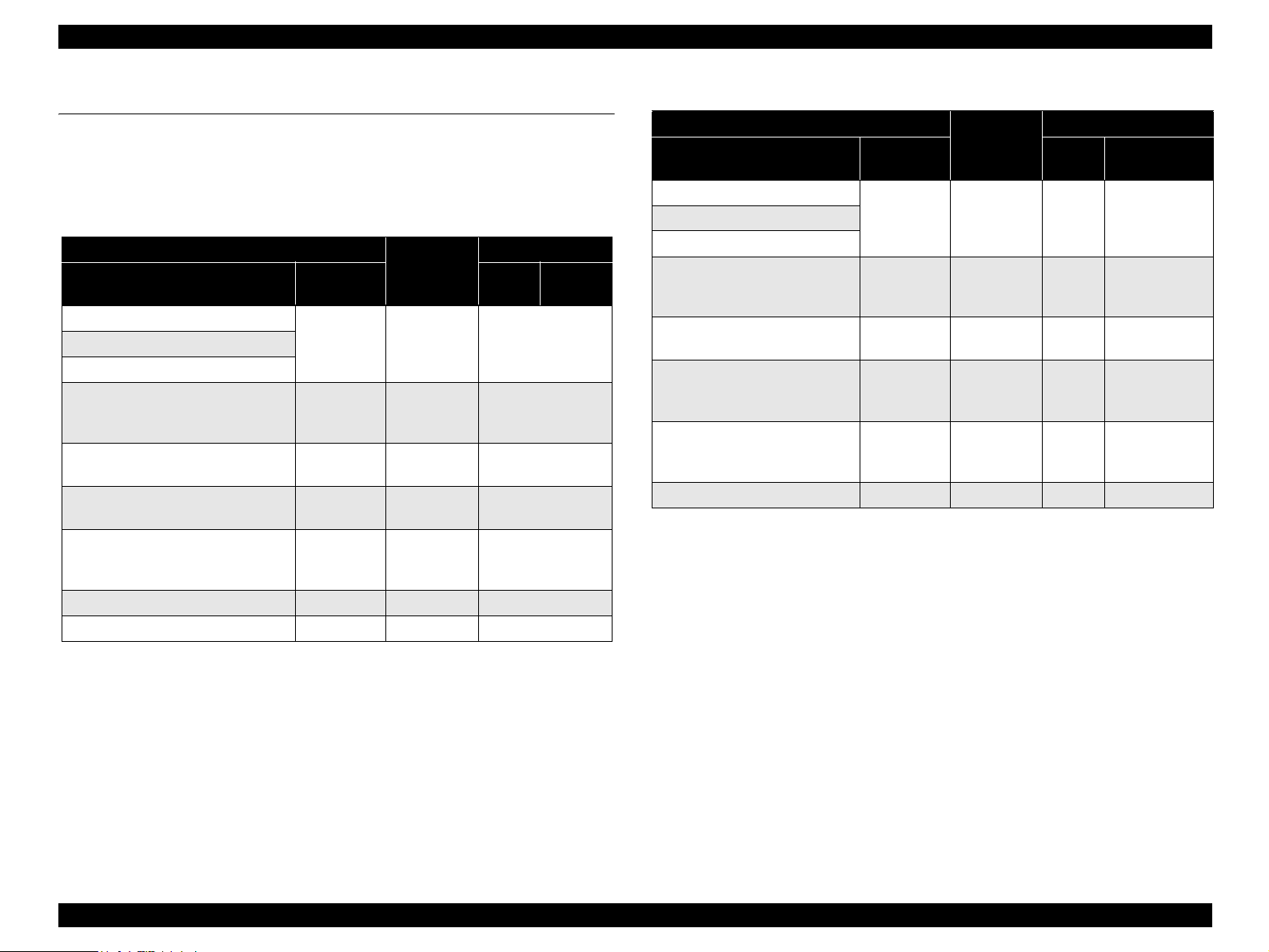
Table 1-29. Supported Paper Sizes, Types and Qualities (for EAI)
Paper type
1
Paper name
Panel
indication
Quality *
Plain Paper
Plain Paper Plain Paper Letter/A4Recycled Paper
Bright White Paper
Premium Photo Paper Glossy *
Premium Photo Paper Semi-gloss*
Photo Paper Glossy*2*
2
3
Photo Paper Photo Paper
2
Photo Paper Photo Paper Letter/A4
Photo Paper Photo Paper
Ultra Premium Photo Paper Glossy*2Photo Paper Photo Paper
Premium Presentation Paper Matte*4Matte Paper Matte Paper Letter/A4
Note : Letter/A4: Selectable by Setup mode only for Latin region.
Note *1 : The quality of draft copy is not affected by “Paper type” selection.
*2: For photo paper: Printing parameter is same as Premium Glossy Photo Paper.
*3: Printing is available, but Color tone is not secured.
*4: Stylus CX5900/CX6000/DX6000/DX6050 only
Paper size
Paper
size
Letter/A4
5" x 7"
4" x 6"
Letter/A4
4" x 6"
Letter/A4
5" x 7"
4" x 6"
Panel
indication
Table 1-30. Supported Paper Sizes, Types and Qualities (for EUR/ASIA)
Paper type
1
Paper name
Panel
indication
Quality *
Plain Paper
Plain Paper Plain Paper A4 A4Recycled Paper
Bright White Paper
Premium Glossy Photo Paper *2Photo Paper Photo PaperA413 x 18
Premium Semigloss Photo
2
Paper*
Glossy Photo Paper*2*
3
Ultra Glossy Photo Paper*
Matte Paper Heavyweight*
2
6
Photo Paper Photo Paper
Photo Paper Photo PaperA413 x 18
Photo Paper Photo Paper
Matte Paper Matte Paper A4 A4
Note *1 : The quality of draft copy is not affected by “Paper type” selection.
*2: For photo paper: Printing parameter is same as Premium Glossy Photo Paper.
*3: Printing is available, but Color tone is not secured.
*4: 10 x 15: The panel indicator only. 10 x 15 is the same size as 4” x 6”
*5: 13 x 18: The panel indicator only. 13 x 18 is the same size as 5” x 7”
*6: Stylus CX5900/CX6000/DX6000/DX6050 only
Paper size
Paper
size
Panel indication
10 x 15
A4
10 x 15A410 x 15/4” x 6”*
13 x 18/5” x 7”*
10 x 15
10 x 15/4” x 6”*
A4
13 x 18
10 x 15
13 x 18/5” x 7”*
10 x 15/4” x 6”*
A4
13 x 18
10 x 15
4
A4
5
4
A4
5
4
PRODUCT DESCRIPTION Memory Card Print 31
Page 32

EPSON Stylus CX4900/CX4905/CX5000/DX5000/DX5050/CX5900/CX6000/DX6000/DX6050 Revision A
1.5.2.2 Memory Card Printing Mode
Print all images
This function prints all of the image files stored in the memory card. As shown
right, the number of printed pages depends on the number of copies to be printed.
The settings are described right.
DPOF printing
In this mode, the photo frame numbers previously specified via the camera are
printed in the number of pages specified via the camera. Only the paper type and
layout are specified on the printer side. If the layout assigned multiple photos per
output sheet, photos that have different frame sizes are automatically assigned in
the specified number of pages in numerical order (of the specified photo frame
numbers). If index print mode was set via the camera, this unit will print in DPOF
index layout. (When in DPOF print mode, the mode cannot be switched by writing
the print file specification from the host after inserting the memory card.)
Print selected image
This function prints selected image file stored in the memory card. The number of
printed pages depends on the number of copies to be printed.
Print index sheet printing
This function prints thumbnail images (stored in the memory card) onto an Index
Sheet (form) that is marked for selecting images.
The combinations of paper types and paper sizes are fixed as shown right.
Print from index sheet printing
This function prints selected images onto the sheet output by index sheet printing.
Table 1-31. Memory Card Printing Mode
Setting Memory card printing mode Description Option, setting range, etc.
Layout
(no menu)
Paper
type
Paper size
Pages/
copies
Quality
• Print from index sheet printing
• Print all images
• DPOF printing
Print index sheet printing Fixed Plain Paper
• Print from index sheet printing
• Print all images
• DPOF printing
Print index sheet printing Fixed A4 or Letter *
• Print from index sheet printing
• Print all images
• DPOF printing
Print index sheet printing Fixed
Print from index sheet printing
Print all images
DPOF printing
Print index sheet printing Fixed
• Print from index sheet printing
• Print all images
• DPOF printing
Sets print
layout
Sets paper
type
Sets paper
size
Sets number
of printout
Sets number
of printout
Sets number
of printout
Sets print
quality
Fixed in combination with paper
type and paper size (refer to
“1.5.4 Layout and Paper Type,
Paper Size” (p.36))
Plain Paper or Photo Paper
1
A4, 10 x 15*2, or 13 x 18
Letter, 4" x 6", or 5" x 7"
Fixed as 1 page (can vary
according to the number of
image files)
1 to 3 (set by the marking to the
index sheet)
1
The number of copies specified
via the camera is used. The
setting range is 1 to 99 copies
(default is 1 copy).
Prints it by the quality of 360 x
720dpi of Plain Paper. Only the
Color print is supported.
Fixed according to paper type
(refer to “1.5.9 Relation
between Paper Type and
Quality” (p.40))
Note *1 : Letter size will be used for EAI.
A4 size will be used for other areas.
Letter/A4 is selectable by setup mode only for Latin region.
*2: The panel indicator only. The printer chalks 10 x 15 format to 4” x 6” format.
PRODUCT DESCRIPTION Memory Card Print 32
Page 33

EPSON Stylus CX4900/CX4905/CX5000/DX5000/DX5050/CX5900/CX6000/DX6000/DX6050 Revision A
1.5.3 Index Sheet
30 thumbnail images are assigned per index sheet.
There are 3 marking areas for each thumbnail and you can set the number of
copies up to 3.
“Paper type” and “Paper size” can be set from the operation panel.
The layout is fixed according to the paper type and it is not indicated on the sheet.
(Refer to “1.5.4 Layout and Paper Type, Paper Size ” (p.36))
Images are arranged in the Index sheet in ascending order (of image file number).
(Refer to “1.5.1.7 File Sorting” (p.30) and “ 1.5.1.8 File Sorting Rules ” (p.30))
Index sheet will be printed from the last page, in descending order. (The sheet
containing first thumbnail comes top of printouts.)
The mode transition may occur from “Print index sheet” to “Print from index
sheet” when the “Print index sheet” completes successfully.
Figure 1-12. Sample of Index Sheet
PRODUCT DESCRIPTION Memory Card Print 33
Page 34

EPSON Stylus CX4900/CX4905/CX5000/DX5000/DX5050/CX5900/CX6000/DX6000/DX6050 Revision A
1.5.3.1 Rules for Scanning Index Sheets
Index sheet scan range
Set index sheet in scanner
• Place the side to be scanned face down relative to the scan bed, as described
below.
Align the corner of the sheet to the upper left origin point and make sure the
sheet is straight. Angled setting of the sheet is allowed as long as the sheet
remains within the scan bed's scan range (the maximum angle on the scan
bed is about 2.8°).
• The cover must be closed on the original to enable scanning. (This is to
prevent any shifting of the position marks while scanning).
• Do not use paper that allows images to “bleed through” to the rear side.
(This is to prevent empty bubbles from being filled in by “bleed-through”.)
Set scan area and original
Table 1-32. Set Scan Area and Original
RW
(readable width)
216 mm (8.5") 1.5 mm ± 1 mm 297 mm (11.7") 1.5 mm ± 1 mm
Place the Index Sheet face down with its top edge aligned to the left edge of
the scan bed, and with the corner of the paper set to the original's top left
position.
(out-of-range left margin)
OLM
RL
(readable length)
(out-of-range top margin)
OLM
RW
OTM
Original's top left alignment position
First pixel
Scan direction
a
OTM
Figure 1-13. Set Scan Area and Original
RL
Operator's side
Set original face down,
with top aligned in the
direction of the origin.
Scan bed
Scan area
PRODUCT DESCRIPTION Memory Card Print 34
Page 35

EPSON Stylus CX4900/CX4905/CX5000/DX5000/DX5050/CX5900/CX6000/DX6000/DX6050 Revision A
Basic specifications for scanning of index sheets
Scanning rules for index sheet
The existence of the following recognition factors is judged using the image
pattern matching. (Image is binary.)
Table 1-33. Symbols Check
Position mark Image Description Remarks
Left and right edges (1 each)
Block codes (30)
Image marks (30 x 3)
Paper type/Paper size (6) Select paper NG if dirty (not scannable)
Layout (2) Select layout NG if dirty (not scannable)
Date format Date format On/Off Optional
Reference point for
index marks
Sheet information
(memory card ID, page)
Determines whether or
not to print pixel
NG if dirty (not scannable)
NG if dirty (not scannable)
Use at least one of these
marks
• The marks can be recognized if 50% or more portion of each of them is
filled.
• For running out and excessive marking out, the two white/black search
patterns shown above are superimposed on the mark, and judgment is made
according to this matching ratio.
• The judgment criteria is as follows: Black matching: 80% or more White
matching: 50% or more.
<Marking example>
• If in accordance with the search rule, judgment is made as shown below.
Errors during scanning or printing of index sheets
• Stops scanning and returns to the menu screen if the card is removed while
an index sheet is being scanned or printed.
• Index sheet error 1 (No index sheet) is displayed if the sheet cannot be
scanned because it is dirty, set backwards, etc.
• Index sheet error 2 (Incorrect marking) is displayed if the image bubbles
cannot be read because they are not filled in correctly.
• Index sheet error 3 (Incorrect card) is displayed if, after printing an index
sheet, you try to print from a non-matching memory card, such as a different
(replacement) card or a re-edited version of the same card.
NOTE: For error display, refer to Figure 1-59 (p62)
OK OK OK
NG
NG
PRODUCT DESCRIPTION Memory Card Print 35
Page 36

EPSON Stylus CX4900/CX4905/CX5000/DX5000/DX5050/CX5900/CX6000/DX6000/DX6050 Revision A
1.5.4 Layout and Paper Type, Paper Size
The layout/paper type and size combinations that can be selected are listed below.
Table 1-34. Layout and Paper Type, Paper Size
Layout Paper type Paper size Description
Border free Photo Paper
1-up with
borders
20-up —
30-up —
80-up —
Note *1 : The panel indictor only. The printer chalks the 10 x 15 format up to 4” x 6” format.
Plain Paper
EAI: Letter, 4” x 6”, 5” x 7”
Other: A4, 10 x 15*1, 13 x 18
EAI: Letter, 4” x 6”, 5” x 7”
Other: A4, 10 x 15, 13 x 18
EAI: 4” x 6”
Other: 10 x 15
EAI: 5” x 7”
Other: 13 x 18
EAI: 4” x 6”, 5” x 7”
Other: 10 x 15, 13 x 18
Prints with no margins along top,
bottom and both sides
Prints with 3 mm margins along
top, bottom and both sides
Prints 20 frames per page, laid out
in 5 columns and 4 rows
(For DPOF index print only)
Prints 30 frames per page, laid out
in 6 columns and 5 rows
(For DPOF index print only)
Prints 80 frames per page, laid out
in 10 columns and 8 rows
(For DPOF index print only)
1.5.6 Trimming Function
A trimming function is provided as a means of coordinating photo data with the types
of photo frames handled by this unit. This function is always activated so that printing
photo data is in shapes that fit these photo frames.
This function is described briefly below.
The printed photo frame and the photo to be printed are matched in length along one
side and the photo is resized along the perpendicular side to fit the frame on that side.
Any part of the photo that does not fit within the photo frame is trimmed away (not
printed).
The image below shows an example in which the photo data is aligned vertically
with the photo frame.
These parts are
trimmed.
The image below shows an example in which the photo data is aligned
horizontally with the photo frame.
Photo frame
(print area)
1.5.5 Options
The functions below will be available by marking to options on the index sheet.
Photo frame
(print area)
Prints all photos one by one shown on the index sheet.
These parts are trimmed.
Figure 1-14. Trimming Function
PRODUCT DESCRIPTION Memory Card Print 36
Page 37

EPSON Stylus CX4900/CX4905/CX5000/DX5000/DX5050/CX5900/CX6000/DX6000/DX6050 Revision A
1.5.7 Assignment Rules for Photo Frame Numbers and Rotation
The rules concerning photo frame numbers that are referred when assigning photos are
described below. The numbers shown in each diagram and photo frame below indicate
the photo frame numbers used for various types of layout.
The direction of the number shown in each photo frame matches the direction of the
printed photo to which the horizontal photo data was allocated. When there are more
pixels vertically than horizontally, the vertical photo data is allocated instead, and the
number shown in the figure below is then rotated 90° before being printed. In Index
printing mode, the numbers are printed as they are shown below, regardless of the
shape of the photo data.
However, when the photo data has an equal number of pixels vertically and
horizontally the photos are printed without rotation, regardless of the layout.
(Note: the vertical photo data refers to when the photo data file itself is set for a vertical
(portrait) orientation. Photo data is defined as the vertical photo data if it is taken by a
digital camera with a portrait position detecting function.)
Top edge
<Border-free>
<20-up>
<1 sheet with borders>
12345678
9 10111213141516
17 18 19 20 21 22 23 24
25 26 27 28 29 30 31 32
33 34 35 36 37 38 39 40
41 42 43 44 45 46 47 48
49 50 51 52 53 54 55 56
57 58 59 60 61 62 63 64
65 66 67 68 69 70 71 72
73 74 75 76 77 78 79 80
12345
<80-up>
678910
11 12 13 14 15
16 17 18 19 20
21 22 23 24 25
26 27 28 29 30
<30-up>
Figure 1-15. Assignment Rules for Photo Frame Numbers and Rotation
PRODUCT DESCRIPTION Memory Card Print 37
Page 38

EPSON Stylus CX4900/CX4905/CX5000/DX5000/DX5050/CX5900/CX6000/DX6000/DX6050 Revision A
1.5.8 Layout Drawings
1.5.8.1 Border Free
BD
H
Figure 1-16. Border Free
C
A
Paper
1.5.8.2 1-up with Borders
A
FEG
C
Printable
area
DB
H
Printable area
Figure 1-17. 1-up with Borders
FEG
Table 1-35. Border Free (unit: mm (inch))
Paper type A B C D E F G H
Letter
4" x 6"*1
5" x 7"
(8.50)
101.60
(4.00)
*1
(5.00)
215.90
*1
A4 210 297 215.08 305.04 2.54 2.54 2.96 4.02
*2
10 x 15
13 x 18
101.60 152.40 106.68 160.53 2.54 2.54 2.82 3.60
*2
Note *1 : Letter, 4" x 6", and 5" x 7" size will be used for EAI models.
*2: 10 x 15, and 13 x 18 size will be used for EMC/Asia, Pacific models.
127
279.40
(11.00)
152.40
(6.00)
178
(7.00)
220.98
(8.70)
106.68
(4.20)
132.08
(5.20)
287.53
(11.32)
160.53
(6.32)
186.04
(7.32)
2.54
(0.10)
2.54
(0.10)
2.54
(0.10)
2.54
(0.10)
2.54
(0.10)
2.54
(0.10)
2.96
(0.12)
2.82
(0.11)
2.96
(0.12)
127 178 132.08 186.04 2.54 2.54 2.96 4.02
4.02
(0.16)
3.60
(0.14)
4.02
(0.16)
Paper type A B C D E F G H
Letter
4" x 6"*1
5" x 7"
(8.50)
101.60
(4.00)
127.0
*1
(5.00)
215.90
*1
A4 210 297 204 291 3.00 3.00 3.00 3.00
*2
10 x 15
13 x 18
101.60 152.40 95.60 146.40 3.00 3.00 3.00 3.00
*2
127.0 178.0 121.0 172.0 3.00 3.00 3.00 3.00
Note *1 : Letter, 4" x 6", and 5" x 7" size will be used for EAI models.
*2: 10 x 15, and 13 x 18 size will be used for EMC/Asia, Pacific models.
Table 1-36. Border Free (unit: mm (inch))
279.40
(11.00)
152.40
(6.00)
178.0
(7.00)
209.90
(8.26)
95.60
(3.76)
121.0
(4.76)
273.40
(10.76)
146.40
(5.76)
172.0
(6.76)
3.00
(0.12)
3.00
(0.12)
3.00
(0.12)
3.00
(0.12)
3.00
(0.12)
3.00
(0.12)
3.00
(0.12)
3.00
(0.12)
3.00
(0.12)
3.00
(0.12)
3.00
(0.12)
3.00
(0.12)
PRODUCT DESCRIPTION Memory Card Print 38
Page 39

EPSON Stylus CX4900/CX4905/CX5000/DX5000/DX5050/CX5900/CX6000/DX6000/DX6050 Revision A
1.5.8.3 20-up
B
A
EF
K
G
J
J
L
J
J
D
H
I
II
C
Figure 1-18. 20-up
1.5.8.4 30-up
A
E
F
G
B
J
D
H
I
C
Figure 1-19. 30-up
Table 1-37. 20-up (unit: mm (inch))
Paper type A B C D E F G H I J K L
101.60
152.40
20.00
20.00
6.10
6.30
19.80
20.30
3.00
3.00
89.30
4" x 6" *
5" x 7" *1*
10 x 15 *
13 x 18 *2*
1
(4.00)
(6.00)
(0.79)
(0.79)
(0.24)
(0.25)
(0.78)
(0.80)
(0.12)
(0.12)
127.00
178.00
29.00
24.60
3.00
3.00
5.00
10.00
1.70
2
(5.00)
(7.00)
(1.14)
(0.97)
(0.12)
(0.12)
(0.20)
(0.39)
3
101.60 152.40 20.00 20.00 6.10 6.30 19.80 20.30 3.00 3.00 89.30 112.30
3
127.00 178.00 29.00 24.60 3.00 3.00 5.00 10.00 1.70 10.00 121.00 163.00
(0.07)
10.00
(0.39)
(3.52)
121.00
(4.76)
112.30
(4.42)
163.00
(6.42)
Paper type A B C D E F G H I J
127.00
1
5" x 7"*
13 x 18*2127.00 128.00 20.0 20.0 4.5 4.5 14.0 14.0 4.5 6.0
(5.00)
178.00
(7.00)
Note *1 : 4" x 6" size will be used for EAI models.
*2: 10 x 15 size will be used for EMC/Asia, Pacific models.
Table 1-38. 30-up (unit: mm (inch))
20.0
(0.79)
20.0
(0.79)
4.5
(0.18)
4.5
(0.18)
14.0
(0.55)
14.0
(0.55)
4.5
(0.18)
6.0
(0.24)
Note *1 : 4" x 6" size will be used for EAI models.
*2: Stylus CX5900/CX6000/DX6000/DX6050 only
*3: 10 x 15 size will be used for EMC/Asia, Pacific models.
PRODUCT DESCRIPTION Memory Card Print 39
Page 40

EPSON Stylus CX4900/CX4905/CX5000/DX5000/DX5050/CX5900/CX6000/DX6000/DX6050 Revision A
1.5.8.5 80-up
B
O
P
1.5.9 Relation between Paper Type and Quality
In this mode, printing is always in color (CMYK), not black ink only.
H
G
L
M
N
Q
I
J
E
K
Print from Index sheet* 1440 x 720 VSD3 On On
Note " * " : Stylus CX5900/CX6000/DX6000/DX6050 only
F
D
C
Figure 1-20. 80-up
Table 1-40. Relation between Paper Type and Quality
Paper type
Plain Paper 720 x 720 VSD3 On On
Photo Paper 1440 x 720 VSD3 On On
Matte Paper* 1400 x 720 VSD3 On On
Index sheet
(Plain Paper)
Print resolution
(H x V dpi)
360 x 720 VSD1 On On
Dot size MW High speed
Table 1-39. 80-up (unit: mm (inch))
Paper type A B C D E F G H I
Letter
A4 210.0 297.0 20.0 20.0 2.0 5.0 18.0 62.0 106.0
Paper type J K L M N O P Q
Letter
A4 150.0 18.0 26.0 76.0 126.0 176.0 226.0 26.0
215.90
(8.50)
163.32
(6.43)
279.40
(11.00)
6.35
(0.25)
20.07
(0.79)
11.94
(0.47)
20.07
(0.79)
64.26
(2.53)
6.10
(0.24)
116.59
(4.59)
6.10
(0.24)
168.91
(6.65)
6.35
(0.25)
221.23
(8.71)
58.67
(2.31)
11.94
(0.47)
111.00
(4.37)
PRODUCT DESCRIPTION Memory Card Print 40
Page 41

EPSON Stylus CX4900/CX4905/CX5000/DX5000/DX5050/CX5900/CX6000/DX6000/DX6050 Revision A
1.6 Photo Mode (Stylus CX5900/CX6000/DX6000/DX6050 only)
Photo mode is a mode to scan the photo and print with the settings of requested paper
size or paper type not involving PC.
1.6.1 Basic Specification
Item Description
Restoration Faded images can be restored with this function.
Number of copies setting
Maximum copy size 216 x 297 mm
Zoom Function Fit to page is provided in this mode.
This function sets the number of copies. The setting range is 1 to
99.
1.6.2 Original Photo Setting Specification
When making prints of your photos, place the photos as described below.
The photograph manuscripts can be set up by side putting, and be set up to three.
Spaces between the edges of the scan bed glass and the photos should be 5 mm or
more, and between each photos should be 10 mm or more.
The photograph manuscript is vertically set up so that there is no inclination for
the manuscript stand.
Origin
5mm
Photo
Photo
10mm
10mm
Photo
Scan bed
glass
5mm
PRODUCT DESCRIPTION Photo Mode (Stylus CX5900/CX6000/DX6000/DX6050 only) 41
Page 42

EPSON Stylus CX4900/CX4905/CX5000/DX5000/DX5050/CX5900/CX6000/DX6000/DX6050 Revision A
1.6.3 Supported Paper Sizes, Types and Qualities
Table 1-41. Supported Paper Size, Quality, Type
Paper type
Paper name Panel indication paper size Panel Indication paper size Panel Indication
Quality
1
*
Plain Paper
Recycled Paper
Plain Paper Letter/A4* A4 Standard 720 x 720 VSD3 On On
Bright White Paper
Premium Photo Paper
Glossy*2 (EAI)
Premium Glossy Photo
Photo Paper
Paper*2(Other)
Premium Photo Paper
Semigloss *2 (EAI)
Premium Semigloss Photo
Photo Paper
Paper*2(Other)
Photo Paper Glossy*2*5
(EAI)
Glossy Photo Paper*2*5
Photo Paper
(Other)
Ultra Premium Photo
2
2
(Other)
(EAI)
Photo Paper
Matte Paper Letter/A4* --- Boarder free 1440 x 720 VSD3 On On
Paper Glossy*
Ultra Glossy Photo
Paper*
Premium Presentation
Paper Matte (EAI)
Matte Paper Heavyweight Matte Paper --- A4 Boarder free 1440 x 720 VSD3 On On
EAI EUR/ASIA
Letter/A4*
5” x 7”
4” x 6”
Letter/A4*
4” x 6”
Letter/A4*
4” x 6”
Letter/A4*
5” x 7”
4” x 6”
10 x 15A410 x 15/4” x 6”*
13 x 18
10 x 15
13 x 18
10 x 15
13 x 18*
10 x 15*
A4
A4
A4
A4
3
4
A4
13 x 18/5” x 7”*
10 x 15/4” x 6”*
A4
13 x 18/5” x 7”*
10 x 15/4” x 6”*
Layout
Resolution
(H x V dpi)
Dot size MW
Boarder free 1440 x 720 VSD3 On On
Boarder free 1440 x 720 VSD3 On On
4
3
Boarder free 1440 x 720 VSD3 On On
4
3
Boarder free 1440 x 720 VSD3 On On
4
Print
direction
Note : Letter/A4: Selectable by Setup mode only for Latin region.
Note *1 : The quality of draft copy is not affected by “Paper type” selection.
*2: For photo paper: Printing parameter is same as Premium Glossy Photo Paper.
*3: 13 x 18: The Printer chalks the 13 x 18 format up to the 5” x 7” format.
*4: 10 x 15: The Printer chalks the 10 x 15 format up to the 4” x 6” format.
*5: Printing is available, but Color tone is not secured.
PRODUCT DESCRIPTION Photo Mode (Stylus CX5900/CX6000/DX6000/DX6050 only) 42
Page 43

EPSON Stylus CX4900/CX4905/CX5000/DX5000/DX5050/CX5900/CX6000/DX6000/DX6050 Revision A
1
1
3
2
5
4
7
6
8
0
0
0
0
0
0
0
0
0
1.7 Setting Modes
1.7.1 Ink Level Check
Stylus CX4900/CX4905/CX5000/
DX5000/DX5050
Ink level indicator LED LCD
Ink levels are 100% after initial charge
The Indicator shows Ink remaining
Management and
viewing of ink
levels
by 4 steps, from 100% to Ink out
When any of ink is low, Ink LED
blinks
When any of ink is out, Ink LED is
turned on
1.7.2 Head Cleaning
Head Cleaning can be done from the operation panel to clear away head clogging.
Stylus CX4900/CX4905/CX5000/DX5000/DX5050:
By pressing the [Ink] button for over 3 seconds.
Stylus CX5900/CX6000/DX6000/DX6050:
By pressing the [Start] button.
1.7.3 Ink Cartridge Replacement
Stylus CX4900/CX4905/CX5000/DX5000/DX5050:
Stylus CX5900/CX6000/DX6000/
DX6050
---
When any of ink is low, ink icon is
displayed at the upper left of LCD
When any of ink is out, replace Ink
error is displayed
1.7.4 Nozzle Check Pattern Print
A nozzle check pattern can be printed to check for any ink clogging. Left ink quantity
of each color is also printed by the unit of 10%.
To activate this function, turn on this unit while depressing [Ink] button (Stylus
CX4900/CX4905/CX5000/DX5000/DX5050)/[Start] button (Stylus CX5900/CX6000/
DX6000/DX6050). After printing the pattern, this unit moves to ordinary standby
status.
The example of nozzle check pattern is explained below.
ROM
ROM
version
version
Stylus CX4900/CX4905/
CX5000/DX5000/DX5050
CPxxxx
QPxxxxxx
Q-PIT version
C: 100% M: 100% Y: 100% Bk: 100%
1
1
1
1
1
1
1
1
1
10
11
20
21
30
31
40
41
50
51
60
61
70
71
80
81
90
<Cyan> <Magenta> <Yellow> <Black>
360dpi VSD Large dot
1
10
11
20
21
30
31
40
41
50
51
60
61
70
71
80
81
90
10
20
30
40
50
60
70
80
90
CExxxx
Remaining ink
1
11
21
31
41
51
61
71
81
quantity
1
2
3
4
5
6
7
8
9
By pressing the [Ink] button.
Stylus CX5900/CX6000/DX6000/DX6050:
32dots
0.212mm (1/120inch)
Ink cartridge exchanging procedure starts by pressing the [Start] button.
Once the Scanner unit is opened and the [Start] button is pressed, the LCD shows
the following displays repeatedly.
1. Current remaining ink level
2. Promote replace Ink cartridges
3. Close the scanner unit and press Start button
When the Scanner Unit is closed and the [Start] button is pressed, the Carriage moves
Figure 1-21. Nozzle Check Pattern (Stylus CX5900/CX6000/DX6000/DX6050)
to the standby position and the ink cartridge exchanging sequence is executed.
Automatically returns to the TOP screen after execution.
PRODUCT DESCRIPTION Setting Modes 43
Page 44

EPSON Stylus CX4900/CX4905/CX5000/DX5000/DX5050/CX5900/CX6000/DX6000/DX6050 Revision A
1.7.5 Head Alignment
Alignment adjustments can be made to maintain high print quality during bi-directional printing. This function can be used for basic adjustments. For more precise adjustments, we
recommend using the head alignment utility that is installed in the connected computer.
Stylus CX4900/CX4905/CX5000/DX5000/DX5050 Stylus CX5900/CX6000/DX6000/DX6050
To activate this
function
Preparation
Print Pattern Turn on this unit while depressing [Copy] button and print the Alignment adjustment pattern.
Adjust VSD1
color parameter
Adjust VSD2
color parameter
Adjust VSD3
color parameter
Adjust VSD4
color parameter
Adjust Eco color
parameter
Termination
By pressing the [Copy mode] button. The pattern will be printed which shows the head alignment
at that time, and adjustment can be done regarding to that pattern.
1. Set A4 or Letter sized paper to the sheet feeder.
2. Set PG position is close.
1. Select the most appropriate value regarding the printed pattern #1 by pressing [Copy] button.*
2. Press [B&W Start] button to terminate VSD1 color parameter adjustment. *
3
1. Select the most appropriate value regarding the printed pattern #2 by pressing [Copy] button.*
2. Press [B&W Start] button to terminate VSD2 color parameter adjustment. *
3
1. Select the most appropriate value regarding the printed pattern #3 by pressing [Copy] button.*
2. Press [B&W Start] button to terminate VSD3 color parameter adjustment. *
3
1. Select the most appropriate value regarding the printed pattern #4 by pressing [Copy] button.*
2. Press [B&W Start] button to terminate VSD4 color parameter adjustment. *
3
1. Select the most appropriate value regarding the printed pattern #5 by pressing [Copy] button.*
2. Press [B&W Start] button to terminate Eco color parameter adjustment. *
3
3. The Eco black adjustment parameter is undergoed a change of the color adjustment.
When all the parameter adjustment is terminated successfully, the adjusted value will be
memorized and this unit will be turned off automatically. The adjusted value will be effective
from next turning on. To indicate the adjusted values are memorized, all the LEDs except for Card
Access LED will be flashing once.
By pressing the [Start] button, the pattern will be printed that shows the head
alignment at that time, and adjustment can be done regarding to that pattern.*
1
Turn on this unit while depressing [Start] button and print the Alignment adjustment
pattern.
2
1. Select the most appropriate value regarding the printed pattern #1. *
4
2. Press [Start] to terminate VSD1 color parameter adjustment.
2
1. Select the most appropriate value regarding the printed pattern #2. *
4
2. Press [Start] to terminate VSD2 color parameter adjustment.
2
1. Select the most appropriate value regarding the printed pattern #3. *
4
2. Press [Start] to terminate VSD3 color parameter adjustment.
2
1. Select the most appropriate value regarding the printed pattern #4. *
4
2. Press [Start] to terminate VSD4 color parameter adjustment.
2
1. Select the most appropriate value regarding the printed pattern #5. *4
2. Press [Start] to terminate Eco color parameter adjustment.
When all the parameter adjustments are completed successfully by pressing the
[Start] button, the adjusted values will be memorized and the LCD display returns to
the top screen. The adjusted values will be effective from the next power-on.
Note *1 : By returning PG to standard (L), the PG error is released and the PG lever operation is displayed (L) and canceled the processing. The print isn’t allowed at PG error. No move to low power
mode in Alignment adjustments
*2: The initial value is “5” indicated on 7 Segment LED and by pressing [Copy button], the value will change from “1” up to “9” incrementally and cyclically.
*3: Just press that button as well when the initial value is the most appropriate.
*4: By pressing the [Up] or [Down] button. The initial value that is indicated on the LCD is “5”.
PRODUCT DESCRIPTION Setting Modes 44
Page 45

EPSON Stylus CX4900/CX4905/CX5000/DX5000/DX5050/CX5900/CX6000/DX6000/DX6050 Revision A
C H E C K
P O I N T
The adjustment procedure will be terminated unsuccessfully in
the following cases and no adjustment will be done.
1. Some error like Paper Out, Paper Jam, PG Open has occurred.
2. The procedure is terminated by pressing Stop button.
3. The unit is turned off.
When Paper Out has occurred, the procedure can restart from
“Print Pattern” by pressing Color Start button. The error should
be removed in advance.
Ink maintenance operation like “exchanging I/C” or “cleaning
head” can not be done in this mode.
<Stylus CX4900/CX4905/CX5000/DX5000/DX5050 specific>
This unit will be turned off automatically when the procedure is
terminated by pressing Stop button and when PG open error
has occurred and then the adjust lever has been set to close
position.
<Stylus CX5900/CX6000/DX6000/DX6050 specific>
When PG open error has occurred and then the Paper
thickness lever has been set to close position.
Stop/Clear button is valid during printing.
Stop/Clear button is invalid in the menu.
1.7.6 Copy Quality
NOTE: This function is only for Stylus CX5900/CX6000/DX6000/DX6050
The resolution for copy with plain paper can be changed. This setting remains after the
printer is turned off.
Default is “Normal”. If the paper size is except A4/Letter, copy quality changes to
normal one at a time.
1.7.7 Borderless setting
NOTE: This function is only for Stylus CX5900/CX6000/DX6000/DX6050 (EAI
and Latin models)
The width of the overhang for borderless setting can be changed.
Default is “Max”. This setting remains after the printer is turned off.
Table 1-43. Borderless Setting
Selected value Margin volume
Max. The overhang width is max.
Mid. The overhang width is half of max.
Min. The overhang width is quarter of max.
1.7.8 Date Stamp
NOTE: This function is only for Stylus CX5900/CX6000/DX6000/DX6050
The captured date is synthesized to the photo and printed based on the Exif information
of the photo data. If the photo data does not include the Exif information, the time
stamp in DOS is used.
Table 1-44. Date Stamp
Set value Captured date
No Date Not printed
mmm.dd.yyyy Printed in this order
dd.mmm.yyyy Printed in this order
yyyy.mmm.dd Printed in this order
Table 1-42. Copy Quality
Selected value Resolution
Normal
Draft 360 x 120
Photo 720 x 720
Monochrome: 360 x 360
Color: 360 x 720 or 360 x 360
1.7.9 Viewer Brightness (Photo Viewer Adjustment)
NOTE: This function is only for Stylus CX5900/CX6000/DX6000/DX6050
This utility is used for adjusting the contrast of the LCD (for user adjustment).
The adjustable range is assumed to be in 5 stages of “-2” to “+2”.
PRODUCT DESCRIPTION Setting Modes 45
Page 46

EPSON Stylus CX4900/CX4905/CX5000/DX5000/DX5050/CX5900/CX6000/DX6000/DX6050 Revision A
1.7.10 Display
NOTE: This function is only for Stylus CX5900/CX6000/DX6000/DX6050 (Asia
models)
This utility is used for selecting display message.
Table 1-45. Display
Selectable value Format
Pictograph Message is icon
English Message is English
1.7.11 Paper size
NOTE: This function is only for Stylus CX5900/CX6000/DX6000/DX6050 (Latin
model)
This utility is used for selecting paper size.
Table 1-46. Date Stamp
Selectable value Panel Paper size LED
A4 A4 On
Letter Letter On
PRODUCT DESCRIPTION Setting Modes 46
Page 47

EPSON Stylus CX4900/CX4905/CX5000/DX5000/DX5050/CX5900/CX6000/DX6000/DX6050 Revision A
1.8 USB Direct-Print/PictBridge Functions
1.8.1 Supported Device
The printer can print from Digital Still Camera tat is compliant with the following
specifications.
• USB DIRECT-PRINT
• CIPA DC-001-2003 Digital Photo Solutions for Imaging Devices
1.8.2 Functions Available from DSC
The following functions are available.
Implementation of each function depends on the DSC.
Table 1-47. Items that can be specified from DSC
Item USB DIRECT-PRINT DPS (PictBridge)
O
DPOF
O
X
Picture
Paper type
Paper size
Layout
Date print
Print quality
Automatic correction
O
Single picture/DPOF
O
Plain paper/Photo paper/Glossy
paper
A4 /5” x 7”/4” x 6”/Letter
X
Layout is fixed in combination
with paper type and paper size.
(2up, 4up and 8up are available
for DPOF)
Enable/Disable
Disable
Disable
Single picture/Multiple picture/
Plain paper/Photo paper
O
Layout is fixed in combination
with paper type and paper size
O
X
X
Table 1-47. Items that can be specified from DSC
Item USB DIRECT-PRINT DPS (PictBridge)
O
Cropping
PRINT Image Framer
Status acquisition O
Start print O
Stop printing
Reset printer O ---
Any area of rectangle.
(This function is available for
Single picture print only)
O
Enable/Disable
Immediately/At the end of page
Any area of rectangle
O
1.8.3 USB Direct-Print/PictBridge Operations
Standard operations are described below
Note *1 : USB DIRECT-PRINT only
*2: DPS (PictBridge) only
1.8.3.1 Preparation
Conditions described below are required before starting printing.
The printer is not printing from the PC.
The printer is not printing from the memory card slot.
The printer is not performing the backup of the memory card.
The error (paper empty, ink end, etc.) is cleared.
O
---
PRODUCT DESCRIPTION USB Direct-Print/PictBridge Functions 47
Page 48

EPSON Stylus CX4900/CX4905/CX5000/DX5000/DX5050/CX5900/CX6000/DX6000/DX6050 Revision A
1.8.3.2 Standard Operations
Standard operations are described below. These operations depend on the DSC.
1. Preparation at the printer
Some settings are required before connecting with the DSC. If your DSC can set
these settings, preparation at the printer is not required.
1. Choose the Paper Type, Paper Size and Layout to the desired setting.
2. Preparation at the DSC
Some operations are necessary before connecting to the printer.
1. Set the DPOF (or select pictures*2) if printing multiple picture.
2. Choose the picture when Single picture print and set area to crop if necessary.
3. Choose the Paper Type and Paper Size (and Layout*
specified from DSC.
3. Start printing
1. Connect the DSC to the printer with a USB cable. The cable that works well
with the DSC is recommended.
2. Start print by operating from the DSC.
3. The Printer print by printing conditions from DSC, if the DSC dose not
designate the printing parameter, the printer prints it by using the printing
condition that is registered to the printer.*
When this unit is connected to a DSC that supports the USB DIRECT-PRINT protocol
(Revision 1.0), print settings, image selection, status monitoring, and print start/stop
commands can be controlled from the DSC.*
2
1
2
) if these settings can be
1.8.3.4 Cancel Print
This unit can be canceled from the DSC. The [Stop] button of the printer is also
available.
1.8.3.5 Operations when the Print is Completed
To print from the memory card, disconnect the USB cable after printing is complete.
1.8.3.6 Exclusive Control Specifications for Paper Type, Size, and Layout
Depending upon the DSC and printer settings, there may be some combinations of
paper type, size, and layout settings that are not supported by this printer. In such a
case, the paper type is given priority; paper size and layout are changed to settings that
will allow printing (the initial settings made on the printer’s operation panel for the
paper type given priority) and the document is printed.
1.8.3.7 Camera direct error executing other processing (error)
(Stylus CX5900/CX6000/DX6000/DX6050 only)
When unsupported equipment are connected during the other processing is executed
(error), the camera direct error is displayed after other processing execution (error).
When the unsupported equipment is connected and other processing ends, it doesn’t
become a camera direct mode and the camera direct error is not displayed.
1.8.3.3 Display when DSC is connected
When DSC is connected with the above conditions:
Stylus CX4900/CX4905/CX5000/DX5000/DX5050: “P” will be displayed with 7
Segment LED.
Stylus CX5900/CX6000/DX6000/DX6050: “Camera Connected” icon will be
displayed on the LDC and the “Print All” LED will be turned on.
PRODUCT DESCRIPTION USB Direct-Print/PictBridge Functions 48
Page 49

EPSON Stylus CX4900/CX4905/CX5000/DX5000/DX5050/CX5900/CX6000/DX6000/DX6050 Revision A
1.9 Control Panel
1.9.1 Control Panel of Stylus CX4900/CX4905/CX5000/ DX5000/DX5050
Buttons
The control panel contains the following buttons, which are used to set and execute
various operations.
All of them are non-lock type buttons.
Table 1-48. Buttons
Button * Function
Power 1 Execute turning on/off this unit.
Memory Card 2
Copy 3
Paper Type 4 Select paper type.
Paper Size 5 Select paper size.
Ink 6 Execute exchanging ink cartridges or head cleaning.
Fit to Page 7 Alternate zoom of “Fit to page” and default (actual; 100%).
B&W Start *
Color Start 9 Start card print or color copy.
Stop 10 Stop job of copying or printing or sometimes work as shift button.
Note " * " : Numbers in the table correspond to the numbers shown in Figure 1-22 (p50).
Note *1 : B&W means “Black and White”.
1
Refer to “1.9.4.1 Stand-alone Copy / Memory Card Print (Stylus CX4900/CX4905/
CX5000/DX5000/DX5050) ” (p.55) for details about each button.
Make transition from “Copy mode” to “Memory Card mode” and
selects one of card print mode.
Make transition from “Memory Card mode” to “Copy mode” and
sets number of copies.
8 Start monochrome copy.
Indicators
The control panel contains 7-segment LED and 13 LEDs, which are used to indicate
various status.
Table 1-49. Indicators (Stylus CX4900/CX4905/CX5000/CX5050)
LED * Function
Power LED [Green] *1A Light at stand-by. Blink while some operation is proceeding.
Error LED [Red] B Light or blink while some error or warning is occurring.
Ink LED [Red] C
Memory Card LED 1-3
1st [Green] Print Index Sheet
2nd [Green] Print From Index Sheet
3rd [Green] *
7-seg. LED *
Decimal Point
LED
Paper Type LED 1,2
1st [Green] Plain Paper
2nd [Green] Photo Paper
Paper Size LED 1-3
1st [Green] 10x15/ 4”x6” (Euro/Asia), 4”x6” (EAI/Latin)
2nd [Green] 13x18/5”x7” (Euro/Asia), 5”x7” (EAI/Latin)
3rd [Green] A4 (Euro/Asia), Letter (EAI), Letter/A4 (Latin)*
Fit to Page LED
[Green]
Card Access LED
[Green] *
Note " * " : Numbers in the table correspond to the numbers shown in Figure 1-22 (p50)
Note *1 : All LEDs except for Power LED will be turned off while printing or scanning by PC.
*2: When DPOF printing is proceeding, this LED is blinking.
*3: When Memory Card Print mode is selected, those LEDs are turned off.
*4: Letter, when the LED is light. A4, when the LED is blinking.
*5: This LED is located near the card slot, not on the control panel.
2
3
5
Light when some ink is out. Blink when some ink is near empty
or in the ink cartridge exchanging procedure.
Light one of them while some memory card print function
showing below is ready or proceeding.
D
Print All / DPOF
Indicate number of copies, or some error codes in error status.
E
Blinks slowly in low power panel status.
Light one of them showing which paper type below is selected.
F
Light one of them showing which paper size below is selected.
G
4
H Light when “Fit to Page” function is effective in copy mode.
Light when available memory card is in a slot. Blink when
-accessing to the card.
PRODUCT DESCRIPTION Control Panel 49
Page 50

EPSON Stylus CX4900/CX4905/CX5000/DX5000/DX5050/CX5900/CX6000/DX6000/DX6050 Revision A
Α
Β
C
D
E
F
G
H
<EAI> <Spanish/Portuguese> <Spanish> <EKL> <ECC> <ESP><Euro>
Figure 1-22. Control Panel (Stylus CX4900/CX4905/CX5000/DX5000/DX5050)
PRODUCT DESCRIPTION Control Panel 50
Page 51

EPSON Stylus CX4900/CX4905/CX5000/DX5000/DX5050/CX5900/CX6000/DX6000/DX6050 Revision A
1.9.2 Control Panel of Stylus CX5900/CX6000/DX6000/ DX6050
Buttons
The control panel contains the following buttons, which are used to set and execute
various operations.
All of them are non-lock type buttons.
Table 1-50. Buttons
Button * Function
Power 1 Execute turning on/off this unit.
Memory Card 2
Copy 3
Paper Type 4 Select paper type.
Paper Size 5 Select paper size.
Photo 11
Setup/Utilities 12
Up/Down 13 Sets number of copies
Left/Right 14 Select print image
Start 15 Start card print or color copy or scan.
Stop/Clear 16
Note " * " : Numbers in the table correspond to the numbers shown in Figure 1-23 (p52) and
Figure 1-24 (p53)
Refer to “1.9.4.2 Stand-alone Copy / Memory Card Print / Photo / Setup/Utilities
(Stylus CX5900/CX6000/DX6000/DX6050) ” (p.57) for details about each button.
Make transition from “Copy mode” or “Photo mode” or “Setup
mode to “Memory Card mode” and selects one of card print mode.
Make transition from “Memory Card mode” or “Photo mode” or
“Setup mode” to “Copy mode” and selects zoom function.
Make transition from “Copy mode” or “Memory Card mode” or
“Setup mode” to “Photo mode”.
Make transition from “Copy mode” or “Memory Card mode” or
“Photo mode” to “Setup mode”.
Stop job of copying or printing or sometimes work at the printing.
Clear the setting value at the non-printing.
Indicators
The control panel contains 2.0 inch LCD and 15 LEDs, which are used to indicate
various status.
Table 1-51. Indicators (Stylus CX5900/CX6000/DX6000/DX6050)
LED * Function
Power LED [Green] *1A Light at stand-by. Blink while some operation is proceeding.
Memory Card LED 1-4
1st [Green] Print Select
2nd [Green] Print All/PictBridge
3rd [Green] Print Index Sheet
4th [Green] Print From Index Sheet
Copy LED 1-2
1st [Green] Fit to Page
2nd [Green] 100%
Photo [Green] L Light while Photo function showing below is ready or proceeding.
Paper Type LED 1-3
1st [Green] Plain Paper
2nd [Green] Photo Paper
3rd [Green] Matte Paper
Paper Size LED 1,2
1st [Green] A4 (Euro/Asia), Letter (EAI), Letter/A4 (Latin)
2nd [Green] 10x15/ 4”x6” (Euro/Asia), 4”x6” (EAI/Latin)
3rd [Green] 13x18/5”x7” (Euro/Asia), 5”x7” (EAI/Latin)
2 inch LCD O Display photo, print number, error, settings, etc.
Card Access LED
[Green] *
Note " * " : Numbers in the table correspond to the numbers shown in Figure 1-23 (p52) and
2
Light one of them while some memory card print function
showing below is ready or proceeding.
J
Light one of them while copy print function shown below is ready
or proceeding.
K
Light one of them showing which paper type below is selected.
M
Light one of them showing which paper size below is selected.
N
Light when available memory card is in a slot. Blink when
-accessing to the card.
Figure 1-24 (p53)
Note *1 : All LEDs except for Power LED will be turned off while printing or scanning by PC.
*2: This LED is located near the card slot, not on the control panel.
PRODUCT DESCRIPTION Control Panel 51
Page 52

EPSON Stylus CX4900/CX4905/CX5000/DX5000/DX5050/CX5900/CX6000/DX6000/DX6050 Revision A
O
J
Κ
14
13
L
M
Α
<EAI> <Euro> <Spanish/Portuguese> <Spanish>
N
16
15
Figure 1-23. Control Panel (Stylus CX5900/CX6000/DX6000/DX6050)(1)
PRODUCT DESCRIPTION Control Panel 52
Page 53

EPSON Stylus CX4900/CX4905/CX5000/DX5000/DX5050/CX5900/CX6000/DX6000/DX6050 Revision A
O
J
Κ
14
13
L
M
Α
<EKI> <ECC/EHK> <ETT> <ESP>
N
16
15
Figure 1-24. Control Panel (Stylus CX5900/CX6000/DX6000/DX6050)(2)
PRODUCT DESCRIPTION Control Panel 53
Page 54

EPSON Stylus CX4900/CX4905/CX5000/DX5000/DX5050/CX5900/CX6000/DX6000/DX6050 Revision A
1.9.3 Method of Changing Modes
This printer has the following modes:
Copy mode
Memory card mode
Photo mode*
Setup mode*
It is possible to enter respective modes by pressing the button with the same name as
each mode. If a memory card is not inserted at power-on, copy mode is selected in
default configuration. Factory settings of each mode are shown below.
Item Copy mode
Paper Type Plain paper Photo Paper Photo Paper Plain Paper
Paper Size A4 or Letter
Zoom 100% --- --- ---
Copy Color*
Sheet*
Mode*
Restoration*
1
1
Table 1-52. Factory Settings of Each Mode
Memory card
mode
4” x 6”*1 or
10 x 15/4” x 6”*
1
1
1
1
Color --- --- ---
1 1 1 ---
--- Print select --- ---
--- --- Off ---
Photo mode*
4” x 6” or
2
10 x 15/4” x 6”*
1
2
Setup mode*
A4 or Letter
1
Note : Setting items except “sheet” is stored as each mode (except setup mode) setting when
pushed the start button, transit to other mode, or the power off timing. The setting will
not be stored when the printer is pulled out from the outlet. At the timing of transition to
the setup mode, setting items including sheet number are stored.
Note *1 : Stylus CX5900/CX6000/DX6000/DX6050 only
*2: The panel indicator only. The printer chalks 10 x 15 format up to 4” x 6” format.
PRODUCT DESCRIPTION Control Panel 54
Page 55

EPSON Stylus CX4900/CX4905/CX5000/DX5000/DX5050/CX5900/CX6000/DX6000/DX6050 Revision A
1.9.4 Operations
For operations of the Stylus CX4900/CX4905/CX5000/DX5000/DX5050 refer to Table 1-53 on page 55
For operations of the Stylus CX5900/CX6000/DX6000/DX6050 refer to Table 1-54 on page 57
1.9.4.1 Stand-alone Copy / Memory Card Print (Stylus CX4900/CX4905/CX5000/DX5000/DX5050)
The functions of this unit caused by each button in stand-alone copy mode or memory card print mode are described in the following table.
Table 1-53. Operations for Stylus CX4900/CX4905/CX5000/DX5000/DX5050
Button
Power Button • Turn on or off this unit.
• Start or advance ink cartridge (I/C) exchanging procedure.
Case
[All inks are enough.] Move carriage (CR) to I/C exchange position.
Ink Button
Ink Button
(Holding over 3
sec.)
Memory Card
Button
Copy Button
[Ink low, Replace ink, Without I/C error] Move CR to each color's ink check position if that color's I/C is ink low or ink out or without I/C. CR moves in the order of Cyan, Magenta, Yellow,
[CR is in some color's ink check position.] Move CR to next color's ink check position or I/C exchange position.
[CR is in I/C exchange position.] Move CR to standby position.
• Invalid while printing, scanning, cleaning head, stopping printing or copying, exchanging I/C, or in error status except for ink out error, paper out error, memory card error, index sheet error, PG error.
• Start cleaning head procedure.
• Invalid while printing, scanning, cleaning head, stopping printing or copying, exchanging I/C, or in error status except for paper out error, memory card error, index sheet error, PG error.
• Make transition from “Stand-alone copy” mode to “Memory card print” mode and select and
light “Print Index Sheet”, or “Print All / DPOF” if DPOF file exists in the card.
• Turn off both 7 Segment LED and “Fit to Page” LED.
• Select “Plain Paper” and “Letter (or A4)”
• Invalid while printing, scanning, cleaning head, stopping printing or copying, exchanging I/C, or in error status except for memory card error, index sheet error, PG error.
• Set number of copies incrementally and indicate it on 7 Segment LED.
Case
[1 to 8] Add 1 and the number becomes 2 to 9.
[9] Indicate “-”, which means 100 copies.
[-] Reset to “1”.
• Invalid while printing, scanning, cleaning head, stopping printing or copying, exchanging I/C, or
in error status.
• Number decreases one by one after 1 copy is finished and return to the beginning number when
all copies are finished. When “-” is indicated, number of copies decreases internally but no
change can be seen on 7 Segment LED.
Stand-alone Copy Memory Card Print
Black.
Function
• Change to next “Memory card print” function.
Case
[Print Index Sheet] Change to “Print From Index Sheet”, and change paper type and
paper size to the one last set in “Print From Index Sheet” or “Print
All / DPOF”.
[Print From Index Sheet] Change to “Print All / DPOF”.
[Print All / DPOF] Change to “Print Index Sheet”, and change paper type and paper
size to “Plain Paper” and “Letter (or A4)”.
• Make transition from “Memory card print” mode to “Stand-alone copy” mode and set number of
copies to “1”.
• Invalid while printing, scanning, cleaning head, stopping printing or copying, exchanging I/C, or
in error status except for memory card error, index sheet error, PG error.
PRODUCT DESCRIPTION Control Panel 55
Page 56

EPSON Stylus CX4900/CX4905/CX5000/DX5000/DX5050/CX5900/CX6000/DX6000/DX6050 Revision A
Table 1-53. Operations for Stylus CX4900/CX4905/CX5000/DX5000/DX5050
Button
Paper Type Button
Paper Size Button
Fit to Page Button
B&W Start Button
Color Start Button
Stop Button
B&W Start Button
+ Stop Button
Color Start Button
+ Stop Button
Stand-alone Copy Memory Card Print
• Alternate paper type of “Plain Paper” and “Photo Paper”. • Alternate paper type of “Plain Paper” and “Photo Paper” which will be used in “Print From Index
• Invalid while printing, scanning, cleaning head, stopping printing or copying, exchanging I/C, or in error status.
• Alternate paper size of “Letter (or A4)” and “4"x6/10x15” and “5” x 7”/13x18”.
(10x15: The panel indicator only. The Printer chalks the 10x15 format up to the 4” x6” format.)
• Invalid while printing, scanning, cleaning head, stopping printing or copying, exchanging I/C, or in error status.
• Alternate “Fit to Page” status and turn on or off the “Fit to Page” LED.
• Invalid while printing, scanning, cleaning head, stopping printing or copying, exchanging I/C, or
in error status.
• Start monochrome copy.
• Invalid while printing, scanning, cleaning head, stopping printing or copying, exchanging I/C, or
in ink out error.
• Move to PG error status when platen gap is large. But when this button is pressed again in that
status, that print will start.
• Load paper in paper out error or double feed error and eject paper in paper jam error.
• Start color copy. • Start memory card print.
• Invalid while printing, scanning, cleaning head, stopping printing or copying, exchanging I/C, or in ink out error.
• Load paper in paper out error or double feed error and eject paper in paper jam error.
• Move to PG error status when platen gap is large. But when this button is pressed again in that status, that print will start.
• Stop job of copying or printing and reset the number of copies to the beginning. • Stop job of copying or printing.
• Eject paper when paper exists or may exist in the paper path.
• Invalid while PC scanning, cleaning head and exchanging I/C.
• Clear some of error status.
• Start draft monochrome copy when “Plain Paper” and “Letter (or A4)” are selected.
• Invalid while printing, scanning, cleaning head, stopping printing or copying, exchanging I/C, or
in ink out error, or without “Letter” or “A4” is selected.
• Move to PG error status when platen gap is large.
• Start draft color copy when “Plain Paper” and “Letter (or A4)” are selected.
• Invalid while printing, scanning, cleaning head, stopping printing or copying, exchanging I/C, or
in ink out error, or without “Letter” or “A4” is selected.
• Move to PG error status when platen gap is large.
Function
Sheet” or “Print All / DPOF”.
• Invalid in “Print Index Sheet”, and then it is fixed to “Plain Paper”.
• Alternate paper size of “Letter (or A4)” and “4"x 6/10x15” and “5” x 7”/13x18” which will be
used in “Print From Index Sheet” or “Print All / DPOF”.
(10x15: The panel indicator only. The Printer chalks the 10x15 format up to the 4” x 6” format.)
• Invalid in “Print Index Sheet”, and then it is fixed to “Letter (or A4)”.
• Invalid. “Fit to Page” LED is always turned off in this mode.
• Invalid but for clearing some error status.
• Clear PG error and start print that was suspended by PG error.
• Clear index sheet error and start “Print from index sheet”.
• Make transition from “Print Index Sheet” to “Print From Index Sheet” when “Print Index Sheet”
finishes successfully, without any error or “STOP” operation.
• Invalid with no card in slots.
• Move to memory card error status when incompatible memory card is inserted or no images
found in the card.
---
---
PRODUCT DESCRIPTION Control Panel 56
Page 57

EPSON Stylus CX4900/CX4905/CX5000/DX5000/DX5050/CX5900/CX6000/DX6000/DX6050 Revision A
1.9.4.2 Stand-alone Copy / Memory Card Print / Photo / Setup/Utilities (Stylus CX5900/CX6000/DX6000/DX6050)
The functions of this unit caused by each button in stand-alone copy, memory card print, photo, or Setup/Utilities modes are described in the following table.
Table 1-54. Operations for Stylus CX5900/CX6000/DX6000/DX6050
Button
Power Button • Turns on or off this unit.
• Alternates to “Fit to Page” status and
lights “Fit to Page” or “100%”.
Copy Button
Memory Card Button
• Invalid while printing, scanning,
cleaning head, stopping printing or
copying, exchanging ink cartridges, or
in error status.
• Makes transition from “Stand-alone
copy” mode to “Memory card print”
mode, selects and lights “Print Select”,
or “Print All / PictBridge” if DPOF file
exists in the card.
• Select paper type and paper size that are
memorized.
• Invalid while printing, scanning, cleaning head, stopping printing or copying, exchanging ink cartridges, or in error status except for memory card error, index sheet error, or
PG error.
Stand-alone copy Memory card print Photo Setup/Utilities
• Makes transition from “Memory card
print” mode to “Stand-alone copy”
mode and sets number of copies to “1”.
• Select paper type, paper size, zoom function, color/monochrome that are memorized.
• Invalid while printing, scanning, cleaning head, stopping printing or copying, exchanging ink cartridges, or in error status except
for memory card error, index sheet error, or PG error.
• Changes to next “memory card print”
function.
Case
[Print Select]:
Changes to “Print All/PictBridge”.
[Print All/PictBridge]:
Changes to “Print Index Sheet”,
and changes paper type and paper
size to “Plain Paper” and “Letter
(or A4)”.
[Print Index Sheet]:
Changes to “Print From Index
Sheet”, and changes paper type and
paper size to the one last set in
“Print From Index Sheet” or “Print
All / PictBridge” or “Print Select”.
[Print From Index Sheet]:
Changes to “Print Select”.
Function
• Makes transition from “Photo” mode to
“Stand-alone copy” mode and sets
number of copies to “1”.
• Makes transition from “Photo” mode to
“Memory card print” mode, selects and
lights “Print Select”, or “Print All /
PictBridge” if DPOF file exists in the
card.
• Memorizes selected paper type and paper size.
• Makes transition from “Setup” mode to
“Stand-alone copy” mode and sets
number of copies to “1”.
• Makes transition from “Setup” mode to
“Memory card print” mode, selects and
lights “Print Select”, or “Print All /
PictBridge” if DPOF file exists in the
card.
PRODUCT DESCRIPTION Control Panel 57
Page 58

EPSON Stylus CX4900/CX4905/CX5000/DX5000/DX5050/CX5900/CX6000/DX6000/DX6050 Revision A
Table 1-54. Operations for Stylus CX5900/CX6000/DX6000/DX6050
Button
Photo Button
Setup/Utilities
Button
Left/Right Buttons
Up/Down Buttons
Paper Type Button
Stand-alone copy Memory card print Photo Setup/Utilities
• Makes transition from “Stand-alone
copy” mode to “Photo” mode.
• Makes transition from “Memory card
print” mode to “Photo” mode.
• Select paper type and paper size that are memorized. • Memorizes selected paper type and
• Invalid while printing, scanning, cleaning head, stopping printing or copying, exchanging ink cartridges, or in error status except for memory card error, index sheet error, or
PG error.
• Makes transition from “Stand-alone
copy” mode to “Setup” mode, and lights
off all the modes LEDs.
• Makes transition from “Memory card
print” mode to “Setup” mode, and lights
off all the modes LEDs.
• Invalid while printing, scanning, cleaning head, stopping printing or copying, exchanging ink cartridges, or in error status except for memory card error, index sheet error, or
PG error.
• Alternates color print and monochrome
• Selects print image. Before scanning
print.
• Invalid while printing, scanning, cleaning head, stopping printing or copying, exchanging ink cartridges, or in error status.
• Sets number of copies incrementally/decrementally. Before scanning
• Invalid while printing, scanning, cleaning head, stopping printing or copying, exchanging ink cartridges, or in error status.
• Alternates paper type of “Plain Paper”,
“Photo Paper”, and “Matte Paper”.
• Alternates paper type of “Plain Paper”,
“Photo Paper”, and “Matte Paper”,
which will be used in “Print All/
PictBridge” or “Print Select”.
• Invalid in “Print Index Sheet”, and then
fixed to “Plain Paper”.
• Invalid in “Print from Index Sheet”, and
then fixed to selected paper type by
Index Sheet.
• Invalid while printing, scanning, cleaning head, stopping printing or copying, exchanging ink cartridges, or in error status.
Function
Before scanning
Invalid.
After scanning
Returns to top screen and sets
number of copies to “1”.
• Makes transition from “Photo” mode to
“Setup” mode, and lights off all the
modes LEDs.
Selects file type and restoration.
After scanning
Select print image.
Invalid.
After scanning
Sets number of copies
incrementally/decrementally.
Before scanning
Invalid.
After scanning
Alternates paper type of “Plain
Paper”, “Photo Paper”, and “Matte
Paper”.
• Make transition from “Setup” mode to
“Photo” mode.
paper size.
• Returns to the original mode selected
before “setup” mode.
• Selects setup menu.
• Selects adjustment value or setting
value.
• Invalid
PRODUCT DESCRIPTION Control Panel 58
Page 59

EPSON Stylus CX4900/CX4905/CX5000/DX5000/DX5050/CX5900/CX6000/DX6000/DX6050 Revision A
Table 1-54. Operations for Stylus CX5900/CX6000/DX6000/DX6050
Button
Paper Size Button
Start Button
Stand-alone copy Memory card print Photo Setup/Utilities
• Alternates paper size of “Letter (or
A4)”, “4” x 6” /10x15”, and “5” x 7”/
13x18”.
• Alternates paper size of “Letter (or
A4)”, “4” x 6”/10x15”, and “5” x 7”/
13x18”, which will be used in “Print
All/PictBridge” or “Print Select”.
• Invalid in “Print Index Sheet”, and then
fixed to “Letter (or A4)”.
• Invalid in “Print from Index Sheet”, and
then fixed to selected paper type by
Index Sheet.
• Invalid while printing, scanning, cleaning head, stopping printing or copying, exchanging ink cartridges, or in error status.
• Starts copy.
• Invalid while printing, scanning,
cleaning head, stopping printing or
copying, exchanging ink cartridges, or
in ink out error.
• Starts memory card printing.
• Makes transition from “Print Index
Sheet” to “Print From Index Sheet”
when “Print Index Sheet” finishes
successfully, without any error or
“STOP” operation.
• Moves to memory card error status
when incompatible memory card is
inserted or no image is found on the
card.
• Invalid if no card is in the slots.
• Invalid while printing, scanning, cleaning head, stopping printing or copying,
exchanging ink cartridges, or in error status.
• Loads paper in paper out error or double feed error and ejects paper in paper jam error.
• Moves to PG error status when platen gap is large. When this button is pressed again in that status, the printing will be started.
Function
Before scanning
Invalid.
After scanning
Alternates paper size of “Letter (or
Before scanning
Executes previewing
After scanning
Starts copy
• Invalid
A4)”, “4” x 6”/10x15”, and
“5” x 7”/13x18”.
• Executes procedure or starts printing.
• Invalid while printing, scanning,
cleaning head, stopping printing or
copying, exchanging ink cartridges, or
in ink out error status.
PRODUCT DESCRIPTION Control Panel 59
Page 60

EPSON Stylus CX4900/CX4905/CX5000/DX5000/DX5050/CX5900/CX6000/DX6000/DX6050 Revision A
Table 1-54. Operations for Stylus CX5900/CX6000/DX6000/DX6050
Button
Stop/Clear Button
Stand-alone copy Memory card print Photo Setup/Utilities
Not in copying or printing status
Resets the setting value (paper size, paper type, number of copies).
Lights all the paper type and paper size LEDs for one second.
In copying or printing status
Stops the copying or printing job.
Ejects paper when paper exists or may exist in the paper path.
Clears some error status.
• Invalid while PC scanning, cleaning head, and exchanging ink cartridges.
Function
Before scanning
Reset the setting value (paper size,
paper type, number of copies).
Light all paper type and paper size
LEDs for 1 second.
Not in copying or printing status
Resets the setting value (paper size,
paper type, number of copies).
Lights all the paper type and paper
size LEDs for one second
Not in copying or printing status
Resets the setting value when the
setup menu is “Auto correct”,
“Borderless setting”, or “Copy
quality”.
Lights all the paper type and paper
size LEDs for one second and
returns to “Check Ink Levels”
screen.
PRODUCT DESCRIPTION Control Panel 60
Page 61

EPSON Stylus CX4900/CX4905/CX5000/DX5000/DX5050/CX5900/CX6000/DX6000/DX6050 Revision A
1.9.4.3 Memory Card Insertion/Ejection
The functions of this unit caused by memory card insertion or ejection are described in
the following table.
Table 1-55. Memory Card Insertion/Ejection
Action Function
• Recognize the card and light Card Access LED if it is right.
Card Insertion
Card Ejection
• The LED blinks while memory access occurs to the memory card.
• The Power LED blinks during the card recognition.
• Return from the low power panel mode.
• Turn off Card Access LED.
• Stop print job while memory card print is in process and eject paper.
• Clear memory card error if memory card is wrong.
1.9.4.4 Connection/Removal of DSC
Table 1-56. Connection/Removal of DSC
Action Function
This unit moves to a DSC direct mode after a device is confirmed for DSC direct,
when a device is connected to EXT. I/F (USB Host). It won’t move to DSC direct
mode when it shows general printing mode or error. It moves to DSC direct mode
Connect
the DSC
to this unit
with USB
cable
Remove
the DSC
from this
unit
Note *1 : For Stylus CX4900/CX4905/CX5000/DX5000/DX5050; LED panel will show ‘P’
when it finished printing or error status has been resolved. (Errors that is related
with memory card, index sheet or PG will be automatically canceled and it moves to
DSC direct mode. Ink-low status will be also ignored.).
“Camera Connected” icon will be displayed with LCD and Change to “Print
Select”*1 when connection was confirmed, not when it moves to DSC direct mode.
If the DSC direct device was connected to EXT I/F and any error has occurred on
confirmation, it shows DSC direct error.
If this unit was on power save mode and DSC direct device was connected, this unit
will be back to usual status and then it confirms connection.
This unit moves to “Memory card print” mode and select and light “Print Select”*2
when condition where device recognition was carried out normally for DSC direct.
During the printing from a device for DSC direct, this unit stops a printing and
moves to “Memory card print” mode and select and light “Print Select”.*
2
When this unit is displaying “DSC direct error”, this unit cancel it error and returns
it in condition of before connection.
and Change to “Print All/DPFOF”
*2: For Stylus CX4900/CX4905/CX5000/DX5000/DX5050; “Print All/DPFOF”
1.9.4.5 Low Power Panel Mode
Without any panel operation for 13*1/15*2 minutes while the printer and scanner unit
are in standby status, this unit moves into the low power panel mode in which power
consumption for the panel decreases. This unit recovers from that mode by pushing any
button but Power Button or printing/scanning by the computer. This unit is turned off
by pushing Power Button in that mode.
Table 1-57. Low Power Panel Mode
Action Function
• Turn off (LCD and *1) all LEDs except for Power LED and Card Access LED.
Transition to
low power
mode
• Blink Decimal Point LED slowly.*
• No move in error status except for memory card error, index sheet error and PG
error.
• Ejecting of memory card or accessing it by PC has no effect on low power
mode.
Recovery
from low
power mode
• Recall the panel status as that before moving to low power panel mode.
• Inserting or ejecting of memory card or accessing it by PC has no effect on low
power mode.
Note *1 : Stylus CX5900/CX6000/DX6000/DX6050
*2: Stylus CX4900/CX4905/CX5000/DX5000/DX5050
2
1.9.4.6 Adjust Lever Function
If paper thickness lever is in wrong position, the printer displays “PG position warning”.
Table 1-58. Adjust Lever Function
Adjust lever
status
PG open
(Displayed “H”)*
(“H” to “L”) *
PG close
(Displayed “L”)*
(“L” to “H”)*
Note *1 : Stylus CX4900/CX4905/CX5000/DX5000/DX5050
*2: Stylus CX5900/CX6000/DX6000/DX6050
• “H” will be displayed with 7 Segment LED for about 3 seconds just
after the adjust lever is changed to “H: Envelope” position.*
1
• “Paper thickness lever was changed” or this image icon will be
2
displayed with LCD.*
• “L” will be displayed with 7 Segment 7 Segment LED for about 3
seconds just after the adjust lever is changed to “L: Cut sheet” position.
• “Paper thickness lever was changed” or this image icon will be
1
2
displayed with LCD.*
• Clear the PG error and print job suspended by PG error when the adjust
lever is changed to “L: Cut sheet position” in the PG error status.
l
Function
1
2
2
PRODUCT DESCRIPTION Control Panel 61
Page 62

EPSON Stylus CX4900/CX4905/CX5000/DX5000/DX5050/CX5900/CX6000/DX6000/DX6050 Revision A
1.9.5 Errors
1.9.5.1 Panel Status
Table 1-59. Printer Condition and Panel Status
1
Paper Type LED Paper Size LED
3
Fit to Page
LED
Card Access
LED
Indicators*2Priority*
LCD *
1
Printer
status
Power
LED
Error
LED
Ink
LED
Indicators*
Memory Card LED
1 2 3 1 2 1 2
7-seg.
LED
3
2
*
Fatal error
Maintenance request
Paper jam
Replace Ink Cartridge/
No Ink Cartridge/
Incorrect ink Cartridge
Paper out
Double feed
PG open
DSC Direct error
Memory card error
Index sheet error 1
Index sheet error 2
Index sheet error 3
Pre-scanning error*
No memory card*
2
2
Unable cleaning error*
Blink Blink Blink Blink Blink Blink “E” blink Blink Blink Blink Blink Blink Blink — E-90 1 1
Blink On On Blink Blink Blink “E” blink Blink Blink Blink Blink Blink Blink — E-91 2 2
— Blink Off — — — — — — — — — — — E-04 3 3
— Off On — — — — — — — — — — — E-01/E-02 4 4
— On Off — — — — — — — — — — — E-03 5 5
— On Off — — — — — — — — — — — E-05 5 6
— Blinks* — — — — “H” blink* — — — — — — — W-30 10 7
— Blinks Off — — — “P” blink* — — — — — — — W-20 6 8
— Blinks* — On* On* On* “1” blink* — — — — — — — W-11/W-10 6 9
— Blinks* — — On* — “2” blink* — — — — — — — E-10 7 10
— Blinks* — — On* — “3” blink* — — — — — — — E-11 8 11
— Blinks* — — On* — “4” blink* — — — — — — — E-12 9 12
— — — — — — — — — — — — — — E-30 — 13
— — — — — — — — — — — — — — I-10 — 14
2
— — — — — — — — — — — — — — E-50 — 15
Ink low (warning) — — Blink — — — — — — — — — — — I-01/I-02 11 16
Maintenance request
(Warning)
2
*
Note " * " : Blinks twice continuously
Note *1 : Stylus CX4900/CX4905/CX5000/DX5000/DX5050 only
— — — — — — — — — — — — — — W-01 — 17
*3: When 2 or more error occur at the same time, one with smaller number of “Priority”
will be indicated.
*2: Stylus CX5900/CX6000/DX6000/DX6050 only
PRODUCT DESCRIPTION Control Panel 62
Page 63

EPSON Stylus CX4900/CX4905/CX5000/DX5000/DX5050/CX5900/CX6000/DX6000/DX6050 Revision A
1.9.5.2 Errors and Occasions
Fatal error: Mechanical or internal problem has occurred.
Maintenance request: Part(s) inside the printer are at the end.
Paper jam: Paper remains in the paper path
Replace Ink Cartridge/No Ink Cartridge/Incorrect ink Cartridge:
Ink is out in some I/C, or no I/C or incorrect I/C is set.
Paper out: Failed to load papers.
Double feed: Two or more papers have been fed during duplex
printing.
PG open: Platen gap is at open position while standalone function.
DSC Direct error: Unsupported device connected to external memory
connection.
Memory card error (incompatible/no data):
Unavailable memory card for this unit, or no image
found in the card when memory card printing started.
Index sheet error (no index sheet/incorrect marking/incorrect card):
No index sheet is recognized/
no marking to index sheet is found/
the different card or updated card is found for that sheet.
Pre-scanning error*: Failure to find photo placed area.
Unable cleaning error*:
Ink low (warning):
Unable head cleaning.
Ink is running low.
1.9.6 Printer Initialization (TBD)
There are four kinds of initialization method, and the following explains each
initialization.
1. Power-on initialization
This printer is initialized when turning the printer power on, or printer recognized
the cold-reset command (remote RS command).
When printer is initialized, the following actions are performed.
(a) Initializes printer mechanism
(b) Clears input data buffer
(c) Clears print buffer
(d) Sets default values
2. Operator initialization
This printer is initialized when turning the printer power on again within 10
seconds from last power off, or printer recognized the -INIT signal (negative
pulse) of parallel interface.
When printer is initialized, the following actions are performed.
(a) Cap the printer head
(b) Eject a paper
(c) Clears input data buffer
(d) Clears print buffer
(e) Sets default values
3. Software initialization
The ESC@ command also initialize the printer.
When printer is initialized, the following actions are performed.
(a) Clears print buffer
(b) Sets default values
4. Power-on initialization except I/F
Note " * " : Stylus CX5900/CX6000/DX6000/DX6050 only.
The printer recognized the IEEE 1284.4 “rs” command.
When printer is initialized, the following action is performed.
(a) Initializes printer mechanism
(b) Clears input data buffer
(c) Clears print buffer
(d) Sets default values except I/F
PRODUCT DESCRIPTION Control Panel 63
Page 64

OPERATING PRINCIPLES
CHAPTER
2
Page 65

EPSON Stylus CX4900/CX4905/CX5000/DX5000/DX5050/CX5900/CX6000/DX6000/DX6050 Revision A
2.1 Overview
This section describes the operating principles of the Printer Mechanism, Scanner
Mechanism and Electrical Circuit Boards.
Main Board
C657 Main Board
Power Supply Board
C610 PSB/PSE Board
Panel Board
C571 PNL Board (EPSON Stylus CX4900/CX4905/CX5000/DX5000/
DX5050)
C657 PNL Board (EPSON Stylus CX5900/CX6000/DX6000/DX6050)
I/F Board
C610 I/F Board
Head Board
C654 HEAD Board
2.2 Printer Mechanism
2.2.1 Printer Mechanism
PG Sensor
PF Roller
Star Wheel
PW Sensor
Carriage Unit
EJ Roller
Change lever
PF ScalePF Encoder Sensor
CR Motor
PF Motor
Timing Belt
CR Encoder
Sensor
LD Roller
Retard Roller
Compression
Spring
PE Sensor
Clutch mechanism
This printer consists of the Print Head, Carriage Mechanism, Paper Loading
Mechanism, Paper Feeding Mechanism, Ink System.
Cap Unit
Pump Unit
Like the previous printers, EPSON Stylus CX4900/CX4905/CX5000/DX5000/
DX5050/CX5900/CX6000/DX6000/DX6050 is equipped with two DC motors; one for
the Paper Loading/Feeding Mechanism and the Pump Mechanism with the CR Lock
Mechanism, and one for the CR Mechanism. The ASF Unit for the Paper Loading
Mechanism uses rear entry front eject system. The Paper Feeding Mechanism uses the
Figure 2-1. Printer Mechanism block diagram
LD Roller and Retard Roller to feed paper to the Printer Mechanism in the same way as
previous printers.
OPERATING PRINCIPLES Overview 65
Page 66

EPSON Stylus CX4900/CX4905/CX5000/DX5000/DX5050/CX5900/CX6000/DX6000/DX6050 Revision A
2.2.2 Print Head
The Print Head is the same D4-CHIPS type as the previous SPC and makes it possible
to perform economy dot printing and variable dot printing.
The Print Head nozzle configuration is as follows.
Nozzle layout
Black: 90 nozzles x 1 row
Color: 90 nozzles x 3 row/color (Cyan, Magenta, Yellow)
The nozzle layout when viewed from the back surface of the Print Head is shown
below.
8.467
(120/360inch)
#C90
#B90
#C89
#B89
#C88
#B88
#B3
#B2
#B1
#C3
#C2
#C1
Paper Feed Direction
2.822
(40/360inch)
#A90
#A89
#A88
A row B row C row D row
#A3
#A2
#A1
Carriage Moving Direction
Figure 2-2. Nozzle layout
The Print Head has the Electric Poles (CSIC Connectors) to store the ink consumption
amount data into the CSIC chip mounted on the Ink Cartridge. By storing the ink
consumption amount data, this printer can detect the ink consumption status, such as
Ink Low/Out condition.
2.822
(40/360inch)
#D90
#D89
#D88
#D3
#D2
#D1
BlackCyan Magenta Yellow
0.07055
(1/360inch)
0.1411
(2/360inch)
0.2117
(3/360inch)
The basic operating principles of the Print Head, which plays a major role in printing,
are the same as the previous printer; on-demand method which uses PZT (Piezo
Electric Element). In order to uniform the ejected ink amount, the Print Head has its
own Head ID (13-digits code for this Print Head for EPSON Stylus CX4900/CX4905/
CX5000/DX5000/DX5050/CX5900/CX6000/DX6000/DX6050) which adjusts PZT
voltage drive features.
So, you are required to store the Head ID pasted on the Print Head into the EEPROM
by using the Adjustment Program when replacing the Print Head, the Main Board Unit,
the Printer Mechanism with new one. (Note: there are no resistor arrays to determine
the Head ID on the Main Board.) And then, based on the stored Head ID into the
EEPROM, the Main Board generates appropriate PZT drive voltage.
Following explains the basic components for the Print Head.
PZT
PZT is an abbreviation of Piezo Electric Element. Based on the drive waveform
generated on the Main Board, the PZT selected by the nozzle selector IC on the
Print Head pushes the top of the ink cavity, which has ink stored, to eject the ink
from each nozzle on the nozzle plate.
Electric poles for CSIC
This Electric Poles connects the CSIC chip mounted on the Ink Cartridge. By
using this poles, current ink consumption amount data is red out from the CSIC
chip. And, the latest ink consumption amount data is written into the CSIC chip.
Nozzle Plate
The plate with nozzle holes on the Print Head surface is called Nozzle Plate.
Filter
When the Ink Cartridge is installed, if any dirt or dust around the cartridge needle
is absorbed into the Print Head, there is a great possibility of causing nozzle clog
and disturbance of ink flow, and alignment failure and dot missing finally. To
prevent this problem, a filter is set under the cartridge needle.
OPERATING PRINCIPLES Printer Mechanism 66
Page 67

EPSON Stylus CX4900/CX4905/CX5000/DX5000/DX5050/CX5900/CX6000/DX6000/DX6050 Revision A
*
Ink Cavity
The ink absorbed from the Ink Cartridge goes through the filter and then is stored
temporarily in this tank called “ink cavity” until PZT is driven.
CSIC Memory chip
Nozzle selector board
Ink cartridge
Electric poles for CSIC
Head ID for the Print Head is
stored to the EEPROM.
PZT
Nozzle plate
Cavity
Filter
Needle
Figure 2-3. Printhead sectional drawing
2.2.2.1 Printing Process
This section explains the process which the Printheads of On-Demand inkjet printers
eject ink from each nozzle.
1. Normal state:
When the printing signal is not output from the Main Board (C657 Main), or the
PZT drive voltage is not applied, the PZT does not change the shape. Therefore,
the PZT does not push the ink cavity. The ink pressure inside the ink cavity is kept
normal. (refer to Figure 2-4 (p.67): Normal state)
2. Ejecting state:
When the print signal is output from Main Board (C657 Main), the nozzle selector
IC located on the Print Head latches the data once by 1-byte unit. Based on the
drive waveform (common voltage) generated on the Main Board, the PZT selected
by the nozzle selector IC pushes the top of the ink cavity. By this operation, the ink
stored in the ink cavity is ejected from nozzles. (refer to Figure 2-4 (p.67):
Ejecting state)
Ink path PZT Ink cavity
Normal state
Nozzle Nozzle plate
PZT drive voltage
Ejecting state
Figure 2-4. Print Head printing process
2.2.2.2 Printing Method
The dot printing systems of EPSON Stylus CX4900/CX4905/CX5000/DX5000/
DX5050/CX5900/CX6000/DX6000/DX6050 are variable dot printing systems.
Variable dot printing
This printing mode is developed to improve the print quality on exclusive paper.
This mode is basically the same as variable dot printing mode used on other
products; micro dot, middle dot and large dot compose this mode. The printing dot
size varies according to the print data and this mode enables to output even sharper
image on exclusive paper.
OPERATING PRINCIPLES Printer Mechanism 67
Page 68

EPSON Stylus CX4900/CX4905/CX5000/DX5000/DX5050/CX5900/CX6000/DX6000/DX6050 Revision A
2.2.3 Carriage Mechanism
The Carriage Mechanism consists of Carriage Unit (including the Print Head, CR
Encoder Board and PW Sensor), CR Motor, Timing Belt and CR Scale etc.
Following figure shows you each component for the CR Mechanism.
2.2.3.1 Carriage Mechanism
The following DC motor controls the CR Mechanism on this printer.
Table 2-1. Carriage Motor specification
Items Specifications
Type DC motor with brushes
Drive Voltage 42V (DC) ± 5% (voltage applied to driver)
Armature resistance 29.1 Ω ± 10%
Inductance 20.1mH ± 25%
Drive Method PWM, constant-current chopping
Driver IC A6627
Close loop control based on the CR Motor (DC Motor) and CR Encoder has
advantages in stabilized print quality.
Heat generation control
Using low-cost DC motors, this product grasps the variations of the torque
constants, coil resistances and power supply voltages of the individual DC motors
adequately to carry out heat generation control according to individual differences.
CR measurement sequence
To set the appropriate drive current value according to the variation of the CR
mechanical load, the mechanical load is measured in a CR measurement sequence
and saved into the EEPROM in a power-on or I/C change sequence. A fatal error
will occur if too much load is applied to the CR drive system.
The above control and sequences correct the drive current value of the CR Motor
according to not only the mechanical load but also the variations of the motor and like.
In addition, the resultant CR drive current value is used to calculate a heating value,
and when the specified heating value is reached, wait time is provided per CR path for
printing.
CR Motor
CR Scale CR Encoder SensorPW Sensor
CR variation measurement sequence
The variations of the torque constant, coil resistance and power supply voltage of
the motor are measured in a CR variation measurement sequence when the CR
Carriage Guide ShaftTiming Belt
Figure 2-5. Carriage Mechanism
Carriage Unit
mechanical load is in the initial status and saved into the EEPROM. According to
the variations (individual differences) measured in this sequence, the voltage is
corrected to make the drive current value constant (without an individual
difference).
OPERATING PRINCIPLES Printer Mechanism 68
Page 69

EPSON Stylus CX4900/CX4905/CX5000/DX5000/DX5050/CX5900/CX6000/DX6000/DX6050 Revision A
2.2.3.2 Carriage Home Position Detection
1. Current position temporary detection sequence determines if the carriage is in the
carriage lock position and releases the carriage if it is locked.
2. The carriage is moved to the left frame hit position and the carriage motor is
stopped.
3. The position that is specified steps right from the stopping place is defined as an
origin, and from that time, positional information is monitored by the linear
encoder.
If the positional information could not be gained during detecting carriage home
position due to the following causes, fatal error occurs.
• Obstructions on the carriage path or other factors are giving too much
pressure on the CR motor.
• CR linear encoder failure, CR linear scale defect, etc.
2.2.3.3 Sequence Used for PW Detection
The PW (paper width detection) Sensor installed on the Carriage Unit bottom is used to
control the printer according to various sequences.
The following briefly describes the PW Sensor operating principle.
A dark voltage is measured by the PW Sensor in three places on the right end plane
(area without the absorber) of the Front Paper Guide every time power is switched on,
and the measurement values are saved into the EEPROM as threshold values.
Threshold value > detection voltage: Paper present
Threshold value < detection voltage: Paper absent
The following sequences are performed.
Paper Left/Right Edge Detection Control
Before start of printing (immediately after the end of paper locating), or during
printing, whether paper is present or not is detected to prevent off-paper printing
on the Paper Guide by borderless printing used in a wrong way.
Paper Top Edge Detection Control
Detects paper leading edge at start of printing. Also sets the amount of extension
for the paper leading edge during borderless printing.
Paper Bottom Edge Detection Control
Sets the amount of extension for the paper trailing edge during printing.
OPERATING PRINCIPLES Printer Mechanism 69
Page 70

EPSON Stylus CX4900/CX4905/CX5000/DX5000/DX5050/CX5900/CX6000/DX6000/DX6050 Revision A
2.2.4 Paper Loading/Feeding Mechanism
The following DC motor controls the Paper loading/feeding mechanism on this printer.
Table 2-2. PF Motor specifications
Item Description
Motor type DC motor with brushes
Drive voltage 42V (DC) ± 5% (voltage applied to driver)
Armature resistance 27.5Ω ± 10%
Inductance 21.4mH ± 25%
Driving method PWM, constant-current chopping
Driver IC A6627
Left side view
PF Motor
Spur Gear 30.8
PF Scale
PF Encoder Sensor
Spur Gear 30.8
The drive of the PF motor is transmitted to the LD roller shaft and the PF roller through
gears for the Paper loading/feeding mechanism. The Paper loading mechanism plays a
role in loading a paper from the ASF unit to the PF roller. And also, the Paper feeding
mechanism plays a role in feeding a paper loaded from the ASF unit. The functions of
the Paper loading/feeding mechanism varies depending on the rotational direction of
the PF motor as the table below.
Table 2-3. ASF unit function & PF Motor rotational direction
Directions * Corresponding functions
Clockwise
• Pick up and feed a paper
• Set the Change Lever on the Clutch mechanism
Counterclockwise • Release the Change Lever from the Clutch mechanism
Note " * " : The PF Motor pinion gear rotation direction = seen from the left side of the printer.
Following shows you the transmission path of the PF Motor drive to the LD Roller, the
PF Roller and the EJ Roller. (The numbers in the following figure show you the order
of transmission path.)
Left side view
PE Sensor
Spur Gear 13.5
(PF roller)
Combination
Gear 27.2, 19.2
Spur Gear 36.8
Paper
Absent
Paper
Present
7
1
PF Motor
pinion gear
2
Spur Gear 32.4
(PF Roller)
3
Spur Gear 36
(EJ Roller)
4
Combination
Gear 21.24
EJ Roller
PF Roller
2
3
Spur Gear 27.2
4
Spur Gear 16
(Change Lever)
6
5
PE Sensor
Lever
Low signal
Paper
High signal
Note : The Clutch gear is molded on the backside of the Spur Gear 36.8 such as Combination gear.
Figure 2-6. Paper loading/feeding mechanism
OPERATING PRINCIPLES Printer Mechanism 70
Page 71

EPSON Stylus CX4900/CX4905/CX5000/DX5000/DX5050/CX5900/CX6000/DX6000/DX6050 Revision A
For your reference, the top or the end of a paper is usually detected with the PE Sensor.
In case that the PE Sensor cannot detect the top of a paper in the paper loading
sequence, the printer indicates the “Paper Out error”. If the PE Sensor cannot detect the
end of a paper in the paper feeding sequence, the printer indicates the “Paper Jam
error”. As for the details, refer to Chapter 3
“TROUBLESHOOTING” (p.90).
2.2.4.1 Paper Loading Mechanism
The Paper loading mechanism consists of the Change Lever in the Pump Unit, the
Holder Shaft Unit (including the Clutch mechanism) and the ASF Unit.
The Change Lever and the Clutch mechanism play a major role in the Paper loading
mechanism as follows.
1. ASF home position detection function
The ASF Unit on this printer does not have the ASF Home Position Sensor.
Instead of the ASF Home Position Sensor, the Change Lever and the Clutch
mechanism is used to detect the ASF home position.
When the Change Lever is set on the Clutch mechanism with the counterclockwise
rotation of the PF Motor pinion gear, the ASF home position is detected by this
lever for the paper loading operation. In this time, the printer cannot load a paper
from ASF Unit because the drive of the PF Motor is not transmitted to the LD
Roller Shaft.
2. Paper loading function
When the Change Lever is released from the Clutch mechanism with the
clockwise rotation of the PF Motor pinion gear, the ASF home position detection
function is changed over to the paper loading function. Therefore, the printer can
load a paper from ASF Unit because the drive of the PF Motor is transmitted to LD
Roller Shaft.
During paper loading, paper is transported from the ASF Unit into the printer by the
rotation of the 2 cams of the LD Roller.
Cam (Large) : Hopper release
Cam (Small) : Paper Back Lever release
When 1 page paper is loaded, the cams mentioned above prepare the Hopper and Paper
Back Lever for the next paper loading operation, and the remaining paper is returned to
the standby position.
Figure 2-7 (p.72) and Figure 2-8 (p.73) show you the ASF paper loading sequence and
the operation of each mechanism.
OPERATING PRINCIPLES Printer Mechanism 71
Page 72

EPSON Stylus CX4900/CX4905/CX5000/DX5000/DX5050/CX5900/CX6000/DX6000/DX6050 Revision A
When the PF Motor pinion
gear rotates CCW direction
(right side view), the
Change Lever pushes down
the Clutch lever as right
figure and the Clutch lock
tooth is disengaged from
the Clutch Gear. As the
result, the LD Roller Shaft
dose not rotate at all
because the drive of the PF
Motor is not transmitted. In
this time, the Hopper is also
pushed down by the two
cams on the LD Roller
Shaft, and the Paper Back
Lever is set to avoid that
papers are slipped down
from the paper set position.
This position is the ASF
home position.
Hopper & Paper Back Lever condition
Hopper release cam
LD Roller Shaft
LD Roller
Paper Back Lever
Torsion spring 6.45
Gear rotation direction (Right side view)
Spur Gear 13.5
(PF Roller)
Step 1 (ASF Home position) Step 2
Hopper & Paper Back Lever condition
Hopper
Compression
Spring 5.58
ASF Frame
Gear rotation direction (Right side view)
Change
lever
Clutch
lever
Clutch Clutch
gear
Clutch lock tooth
To Front side
Extension Spring
0.143
When a paper is loaded
from the ASF Unit, the
Change Lever moves to the
front side of the printer with
the CW rotation (right side
view) of the PF Motor
pinion gear and releases the
Clutch lever. As the result,
the Clutch turns back to the
engagement position by the
tension force of the
Extension Spring 0.143.
And, the Clutch gear is
engaged with the Clutch
lock tooth to transmit the
drive of the PF Motor as left
figure. In this time, the
Change Lever is locked
instantaneously by the
protrusion on the backside
of the Carriage Unit to
change over from the ASF
home position detection
function to the paper
loading function surely.
<PF Motor drive transmission path for ASF home position setting>
PF Motor pinion gear (CCW) → Spur Gear 30.8 (CW) →
Spur Gear 32.4 (PF Roller) (CCW) → Spur gear 13.5 (PF Roller) (CCW) →
Combination Gear 21.24 (CW) → Spur Gear 27.2 (CCW) →
Spur Gear 16 (CW) → Change Lever (CW) →
Combination Gear 27.2, 19.2 (CCW) → Spur gear 36.8 (CW)
* Above transmission pass = seen from the right side of the printer
<PF Motor drive transmission path for ASF home position setting>
PF Motor pinion gear (CW) → Spur Gear 30.8 (CCW) →
Spur Gear 32.4 (PF Roller) (CW) → Spur gear 13.5 (PF Roller) (CW) →
Combination Gear 21.24 (CCW) → Spur Gear 27.2 (CW) →
Spur Gear 16 (CCW) → Change Lever (CCW) →
Combination Gear 27.2, 19.2 (CW) → Spur gear 36.8 (CCW)
* Above transmission pass = seen from the right side of the printer
Figure 2-7. ASF paper loading sequence (Step 1, 2)
OPERATING PRINCIPLES Printer Mechanism 72
Page 73

EPSON Stylus CX4900/CX4905/CX5000/DX5000/DX5050/CX5900/CX6000/DX6000/DX6050 Revision A
The PF Motor pinion gear
rotates CCW direction (right
side view), and the drive of
the PF Motor is transmitted
to the LD Roller Shaft
through the Clutch lock
tooth and the Clutch gear.
After the LD Roller pushes
down the Paper Back Lever
into the ASF Frame, the
Hopper is released by the
tension force of the
Compression Spring 5.58.
And, a paper is picked up
with the frictional force
between the LD Roller and
the Pad Hopper.
Hopper & Paper Back Lever condition
Hopper release cam
Gear rotation direction (Right side view)
Step 3 Step 4
Hopper & Paper Back Lever condition
1
3
2
Hopper release cam
Compression
Spring 5.58
Paper Back Lever
Gear rotation direction (Right side view)
LD Roller Shaft
1
2
While the LD Roller rotates
CCW direction (right side
view) continuously, the top of
a paper is loaded to the PF
Roller. In this rotation, the
Hopper returns to the open
3
position and the Paper Back
Lever is pushed up by the
cam of the LD Roller. In this
ASF Frame
time, this lever returns papers
to the stand-by position in
ASF Unit for next paper
loading operation.
Then, when the rolling LD
Roller & the Clutch come at
the above “Step1” position,
the Clutch lever is locked
with the Change Lever again.
In this time, the drive of the
PF Motor is interrupted and
the drive is transmitted only
to the PF Roller side for the
paper feeding sequence.
<PF Motor drive transmission path for ASF home position setting>
PF Motor pinion gear (CCW) → Spur Gear 30.8 (CW) →
Spur Gear 32.4 (PF Roller) (CCW) → Spur gear 13.5 (PF Roller) (CCW) →
Combination Gear 21.24 (CW) → Spur Gear 27.2 (CCW) →
Spur Gear 16 (CW) → Change Lever (CW) →
Combination Gear 27.2, 19.2 (CCW) → Spur gear 36.8 (CW)
* Above transmission pass = seen from the right side of the printer
<PF Motor drive transmission path for ASF home position setting>
PF Motor pinion gear (CCW) → Spur Gear 30.8 (CW) →
Spur Gear 32.4 (PF Roller) (CCW) → Spur gear 13.5 (PF Roller) (CCW) →
Combination Gear 21.24 (CW) → Spur Gear 27.2 (CCW) →
Spur Gear 16 (CW) → Change Lever (CW) →
Combination Gear 27.2, 19.2 (CCW) → Spur gear 36.8 (CW)
* Above transmission pass = seen from the right side of the printer
Figure 2-8. ASF paper loading sequence (Step 3, 4)
OPERATING PRINCIPLES Printer Mechanism 73
Page 74

EPSON Stylus CX4900/CX4905/CX5000/DX5000/DX5050/CX5900/CX6000/DX6000/DX6050 Revision A
2.2.4.2 Paper Feeding Mechanism
The Paper feeding mechanism consists of PF Motor, PF Roller, EJ Roller, PE Sensor,
PF Encoder and PF Scale etc. The Paper feeding mechanism feeds a paper loaded from
ASF Unit by using pairs of rollers.
1. One pair is the PF Roller and the Paper Guide Roller which is assembled in the
Paper Guide Upper Unit. The drive of the PF Motor is transmitted to the Paper
Guide Roller through the PF Roller.
2. Another pair is the EJ Roller and the Star Wheel which is assembled on the EJ
Frame Unit. The drive of the PF Motor is transmitted to the Star Wheel through the
EJ Roller.
Left side view
Spur Gear 30.8
PF Encoder Sensor
Paper guide roller
Spur Gear 30.8
Star Wheel
Following figure shows you the transmission path for the PF Roller & the Paper Guide
Roller and the EJ Roller & the Star Wheel.
The top of a paper is loaded to the PF Roller from the ASF Unit in the paper loading
sequence. And then, when the PF Motor pinion gear rotates CW direction (left side
view), a paper is fed by the PF Roller & the Paper Guide Roller and the EJ Roller & the
Star Wheel in the printing operation & the paper feed sequence.
PF Motor
PF Motor
pinion gear
Spur Gear 32.4
(PF Roller)
Transmission path (left side view)
• PF Motor pinion gear (CW) → Spur Gear 30.8 (CCW) → Spur gear 32.4 (PF Roller) (CW)
• PF Motor pinion gear (CW) → Spur Gear 30.8 (CCW) → Spur gear 32.4 (PF Roller) (CW) → Spur Gear 30.8 (CCW) → Spur Gear 36 (EJ Roller) (CW)
PF Scale
Spur Gear 36
(EJ Roller)
PF Roller
EJ Roller
Figure 2-9. Paper feeding mechanism
OPERATING PRINCIPLES Printer Mechanism 74
Page 75

EPSON Stylus CX4900/CX4905/CX5000/DX5000/DX5050/CX5900/CX6000/DX6000/DX6050 Revision A
2.2.5 Ink System Mechanism
The Ink System Mechanism consists of Pump mechanism with Carriage lock
mechanism and Capping mechanism with Wiper mechanism. Following table lists the
function for each mechanism.
Table 2-4. Function for each mechanism
Mechanism Function
Capping mechanism *
Wiper mechanism
Pump mechanism
Carriage lock mechanism
Note : Like the previous printers (Stylus Photo R300/R310), this printer adopts the valveless
cap system. The air valve system used for the previous printer (Stylus COLOR 740)
have two functions by the CR position in the capping condition as follows.
This is to cover the surface of the Print Head with the cap in
order to prevent the nozzle from increasing viscosity.
This is to remove the foreign material and unnecessary ink on
the nozzle plate of the Print Head.
This is to eject the ink from the Ink Cartridge, the ink cavity and
the cap to the Waste Ink Pad.
This is to lock the Carriage Unit with the Change Lever while
the Carriage Unit is at the home position.
1) Valve closing condition (CL position)
By closing the air valve, the ink is forcibly absorbed from the Ink Cartridge
or the ink cavity by the Pump Unit and is ejected to the Waste Ink Pad while
the Carriage Unit is in the CL position.
2) Valve opening condition (Ink absorption position)
By opening the Air valve, the negative pressure is decreased and only the
ink inside the Cap is ejected while the Carriage Unit is in the further right
side than the CL position. (the ink is not absorbed from the Ink Cartridge or
the ink cavity.)
The following shows you the Carriage Unit position for each condition easily.
Printing area CR home position
CL position
(valve closing condition)
Ink absorption position
(valve opening condition)
But, on the valveless cap system, the above 2) operation is done outside the
capping position. The Carriage Unit moves outside the CR home position and
the pump absorbs the ink inside the Cap.
OPERATING PRINCIPLES Printer Mechanism 75
Page 76

EPSON Stylus CX4900/CX4905/CX5000/DX5000/DX5050/CX5900/CX6000/DX6000/DX6050 Revision A
2.2.5.1 Capping Mechanism
The Capping mechanism covers the Print Head with the Cap to prevent the nozzle from
increasing viscosity when the printer is in stand-by state or when the printer is off.
When the Carriage Unit is in the
home position, the hook of the Slider
Lock Lever is not latched to the dent
of the Cap Frame.
In this time, the protrusion of the Cap
Slider Lever does not reach the
rightmost position of the Cap Frame.
Capping position (CR home position)
Step 1
Protrusion
Not latched
Wiper with the Cap unit
The wiping operation is controlled by the Carriage Unit movement. This operation
is usually performed with every CL sequence which is to absorb the ink from the
ink cartridge, the ink cavity by the Pump unit. Following figure shows you the
mechanism for the wiping operation.
Step 2
The Carriage Unit moves to the Wiper
setting position on the rightmost
position of the Cap Frame with keeping
the Cap covered.
In this time, the hook of the Slider Lock
Lever is latched to the dent of the Cap
Frame.
Latched
Wiper setting position
When the Carriage Unit moves to the
left side from the Wiper setting
position, the Cap Unit is pulled back
by the tension force of the
Spring 0.788
.
Extension
In this time, the Cap Unit is
automatically set to the wiping
position because the hook on the
Slider Lock Lever is latched to dent
of the Cap Frame. And, the wiping
operation is performed according to
the Carriage Unit movement.
Step 3 Step 4
Protrusion of the Carriage Unit
Wiping position
Latched
Released
Released position (Bottom position)
When the wiping operation is
finished and the Carriage unit
moves further to the left side,
the hook of the Carriage unit
hits to the Slider lock lever.
In this time, the Slider lock
lever is released and the Cap
slider returns to the bottom
position completely.
(The broken line is the
position of the Carriage unit
& the Slider lock lever just
before being released.)
Figure 2-10. Wiper mechanism
OPERATING PRINCIPLES Printer Mechanism 76
Page 77

EPSON Stylus CX4900/CX4905/CX5000/DX5000/DX5050/CX5900/CX6000/DX6000/DX6050 Revision A
2.2.5.2 Pump Unit Mechanism
The PF Motor also controls the Pump Unit mechanism (including the Change Lever) as
well as the Paper loading/feeding mechanism. The drive of the PF Motor is always
transmitted to the Pump Unit. (And also, its drive is transmitted to the LD Roller
through the Clutch mechanism & the Change Lever.)
On this printer, the Pump Unit mechanism including the Change Lever plays a major
role expecting the ink eject operation. And, these operations control depending on the
PF Motor rotational direction as the following table below.
Table 2-5. PF Motor rotational direction & Ink system mechanism
Directions * Functions
Clockwise • Pump release
Counterclockwise
Note "* " : The PF Motor rotational direction = seen from the left side of the printer.
Spur Gear 30.8
• Absorbs the ink
• Release the Change Lever from the Clutch mechanism
Left side view
1. Ink eject operation (usual operation)
The ink is absorbed from the Ink Cartridge, the ink cavity and is ejected to the
Waste Ink Pad from the Cap when the Ink Tube is pressed by a roller in the Pump
Unit.
Following figure shows you the overview of the Pump Unit mechanism operation.
Cap Unit
side
Waste Ink
Pad side
Note : The PF Motor rotational direction = seen from the right side of the printer.
Figure 2-11. Pump mechanism
Pump Unit
Spur Gear 27.2
(Pump Unit gear)
Right side view
PF Motor
pinion gear
Spur Gear 32.4
(PF Roller)
Cap Unit
Spur Gear 13.5
(PF roller)
Combination
Gear 21.24
Transmission Path: PF Motor pinion gear (CW) → Spur Gear 30.8 (CCW) → Spur Gear 32.4 (PF Roller) (CW) → Spur gear 13.5 (PF Roller) (CW) →
Combination Gear 21.24 (CCW) → Spur Gear 27.2 (Pump Unit gear) (CW)
(Above transmission pass = seen from the right side of the printer)
Figure 2-12. PF Motor drive transmission path to the Pump Unit
OPERATING PRINCIPLES Printer Mechanism 77
Page 78

EPSON Stylus CX4900/CX4905/CX5000/DX5000/DX5050/CX5900/CX6000/DX6000/DX6050 Revision A
2. Carriage lock operation by the Change Lever
Unlike the previous printer (Stylus COLOR 680), this printer does not have the
Carriage Lock Lever with the Wiper.
Instead of the Carriage Lock Lever, the Change Lever is set to the front side of the
printer while the Carriage Unit is in the CR home position.
(As for the detailed mechanism for setting the Change Lever, refer to Figure 2-7
(p.72) Step 2)
2.2.6 Ink Sequence
Initial ink charge
After the printer is purchased and the power is turned on for the first time, the
printer must perform the Initial Ink Charge to charge the ink inside the ink cavity.
When the Initial Ink Charge is completed properly, the printer releases the flag
inside the EEPROM. Initial Ink Charge will take about 100 seconds for Stylus
CX4900/CX4905/CX5000/DX5000/DX5050/CX5900/CX6000/DX6000/
DX6050. If the power is turned off during the Initial Ink Charge, the CL3 will be
performed at next power on timing.
Manual Cleaning
The Stylus CX4900/CX4905/CX5000/DX5000/DX5050/CX5900/CX6000/
DX6000/DX6050 provides three types of manual cleaning to clean air bubbles,
clogged ink with viscosity or foreign substances.
The manual CL can be performed by the Control Panel Operation, the Printer
Driver Utility and the Adjustment Program.
CL1
• Ink absorption (Maximum)
Black Ink: 0.181g, Color Ink: 0.543g
• Wiping operation
Wipes the nozzle plate by the rubber part on the Cap Unit.
• Flashing operation
Prevents color from mixing, and stabilizes ink surface inside the nozzle.
CL2
• Ink absorption (Maximum)
Black Ink: 0.445g, Color Ink: 1.335g
• Wiping operation
Wipes the nozzle plate by the rubber part on the Cap Unit.
• Flashing operation
Prevents color from mixing, and stabilizes ink surface inside the nozzle.
CL3
• Ink absorption (Maximum)
Black Ink: 1.015g, Color Ink: 3.045g
• Wiping operation
Wipes the nozzle plate by the rubber part on the Cap Unit.
• Flashing operation
Prevents color from mixing, and stabilizes ink surface inside the nozzle.
OPERATING PRINCIPLES Printer Mechanism 78
Page 79

EPSON Stylus CX4900/CX4905/CX5000/DX5000/DX5050/CX5900/CX6000/DX6000/DX6050 Revision A
Independently of the printing path after the previous CL, perform manual CL from
CL1 to CL3 in order if the cumulative printing timer counter is less than 9min.
Only when the cumulative printing timer counter is more than 9min, execute only
CL1.
Additionally, if the I/C is Ink Low or Out condition, any manual cleaning is
prohibited and it is displayed on the LED indicators.
Timer Cleaning
Like the previous printers, this printer dose not have Lithium battery which is used
for the backup power source for Timer IC. So, this printer manages the printer off
period or cleaning cycle by using the following method.
The Printer Driver sends the timer command to the printer before printing. The
timer command is generated based on the PC’s timer and it consists of year,
month, date, hour, minute and second. As soon as the printer receives the timer
command from the Printer Driver, the printer stores its command in address
06<H> and 07<H> in the EEPROM. Then, it is compared with the latest CL time
which is stored in address 04<H> and 05<H> in the EEPROM. And, In case that
the timer cleaning period is over the specific period, the printer performs the timer
cleaning automatically. In this time, the printer stores the timer command in
address 04<H>, 05<H>, 06<H>, 07<H> in the EEPROM.
Maximum 3.32g of the ink is consumed in the timer cleaning. (0.830g of black ink
and 2.490g of color ink are consumed.)
Flashing
Two different flushing operations are executed for the following reasons.
Pre-printing flushing
This is done before a start of printing to eliminate ink viscosity in the Print
Head nozzles.
Periodic flushing
This is done during printing to prevent ink viscosity in the Print Head nozzles
from increasing.
OPERATING PRINCIPLES Printer Mechanism 79
Page 80

EPSON Stylus CX4900/CX4905/CX5000/DX5000/DX5050/CX5900/CX6000/DX6000/DX6050 Revision A
2.3 Scanner Mechanism
The Scanner Mechanism of Stylus CX4900/CX4905/CX5000/DX5000/DX5050/
CX5900/CX6000/DX6000/DX6050 is constructed of a Scanner Carriage Unit,
Scanner Motor, Scanner HP Sensor, etc., in the same way as previous A4 size scanners.
2.3.1 Scanner Carriage Mechanism
2.3.1.1 Scanner Carriage Unit Overview
The Scanner Carriage Unit is constructed of a CIS Board (including linear CCD), Rod
Lens Array, LED (light source), etc.
CIS Board
CIS Board contains the sensing elements that are placed across the entire width of
an original. The sensing elements, which does not install a color filter, read an
original through the Rod Lens Array by turning on red, green, and blue lightemitting diodes (LEDs) alternately. It is not the CIS Board but the Main Board that
converts the analog light signal read by the Rod Lens Array into digital signal.
Rod Lens Array
A number of rod-shaped lenses, which are arranged on the sensing elements, are
also placed across the entire width of an original. These lenses read the light
reflected from the original that is produced by the light source (LEDs) and pass the
information to the sensing elements. Compared to conventional CCD method, this
optical system allows the focal length (distance between sensor and image
scanned) to be shallow. Therefore, an original to be scanned should be brought
close to the document glass. The optical system, in addition, is 1:1, (there is no
optical reduction or enlargement) and this results in a scanner offering the solid
performance in terms of accuracy.
Scanner Carriage UnitScanner HP Sensor Scanner Carriage Shaft
Scanner Motor Timing Belt
Figure 2-13. Scanner Mechanism
LEDRod Lens Array
CIS
LED
EPSON Stylus CX4900/CX4905/CX5000/DX5000/DX5050/CX5900/CX6000/
DX6000/DX6050 use three color LEDs (the three colors being red, green, and
blue) to illuminate the line to be scanned in the document. Unlike cold cathode
fluorescent lamp used in CCD method, usage of LEDs requires no warm-up time
and allows the CIS to be highly power efficient.
Scanner Carriage Unit
Figure 2-14. Scanning image
CIS Board
OPERATING PRINCIPLES Scanner Mechanism 80
Page 81

EPSON Stylus CX4900/CX4905/CX5000/DX5000/DX5050/CX5900/CX6000/DX6000/DX6050 Revision A
2.3.1.2 Scanner Carriage Unit Movement Overview
Scanning image is performed in the main scan direction (=1 line) by the CIS board and
in the sub-scan direction (=several lines) combined with Scanner Carriage Unit
movement. (refer to the figure below) The CIS board can scan 1 line in main scan
direction (parallel to the Scanner Carriage Unit) by one time. When scanning next lines
after the second line in sub-scan direction, CR driving moves the Scanner Carriage
Unit, and scan the other lines. The scanned data is sent to the control board. The
scanned data for “n” lines and “n-1” line are processed consecutively.
1st line 2nd line 1 pixel
Scanner Carriage
Unit
Sub-scan direction by Scanner Carriage Unit movement
Figure 2-15. Scanner Carriage Unit movement
Document
Main-scan
direction
Drive of the Scanner Motor is transferred to the Scanner Carriage Unit by the Scanner
Timing Belt. The Scanner Carriage Unit slides in the secondary scanning direction.
The Scanner Motor uses a stepping motor and drives using open loop control.
When the HP detection flag of the Scanner Carriage Unit disrupts the signal of the
Scanner HP Sensor, the Scanner HP Sensor outputs a high signal, and the Scanner
Carriage Unit is determined to be in the home position.
Right side
Scanner HP Sensor
Scanner Motor
Left side
Flag
The table below shows the specifications for the stepping motor that controls the
Scanner Carriage Mechanism.
Table 2-6. Scanner Motor specifications
Item Description
Motor type PM type stepping motor
Drive voltage 42V (DC)
Coil resistance 37Ω ± 10% (per phase at 25 degrees)
Inductance TBD mH ± TBD% (1KH 1Vrms)
Driving method PWM
Driver IC A6627
Figure 2-16. Scanner Carriage Unit Mechanism
Scanner Carriage Unit
OPERATING PRINCIPLES Scanner Mechanism 81
Page 82

EPSON Stylus CX4900/CX4905/CX5000/DX5000/DX5050/CX5900/CX6000/DX6000/DX6050 Revision A
2.4 Electrical Circuit Operating Principles
The electric circuit of the CX4900/CX4905/CX5000/DX5000/DX5050/CX5900/
CX6000/DX6000/DX6050 consists of the following boards.
Main Board (CPU-ASIC 2 in 1 + Soldering Flash ROM)
C657 Main Board
Power Supply Board
C610 PSB/PSE Board
Panel Board
C571 PNL Board (EPSON Stylus CX4900/CX4905/CX5000/DX5000/
DX5050)
C657 PNL Board (EPSON Stylus CX5900/CX6000/DX6000/DX6050)
I/F Board
C610 I/F Board
Head Board
C654 HEAD Board
NOTE: CPU and ASIC is integrated as one chip (IC8) on the Main Board.
2.4.1 C610 PSB/PSE Board
In the PSB/PSE Board of Stylus CX4900/CX4905/CX5000/DX5000/DX5050/
CX5900/CX6000/DX6000/DX6050, the simulated oscillating stimulation flyback
converter circuit method is used, and it supplies +42VDC to the drive line. The
application of the output voltage is described below.
Table 2-7. Application Of The DC Voltages
Voltage Application
• Motors (CR Motor, PF Motor, Scanner Motor)
+42VDC
AC voltage input from AC inlet first goes through filter circuit that removes high
frequency components and is then converted to DC voltage via the rectifier circuit and
the smoothing circuit. DC voltage is then lead to the switching circuit and FET Q1
preforms the switching operation. By the switching operation of the primary circuit,
+42VDC is generated and stabilized at the secondary circuit.
• Print Head common voltage
• Print Head nozzle selector 42V drive voltage
This section provides operating principles of C657 Main Board and C610 PSB/PSE
Board.
OPERATING PRINCIPLES Electrical Circuit Operating Principles 82
Page 83

EPSON Stylus CX4900/CX4905/CX5000/DX5000/DX5050/CX5900/CX6000/DX6000/DX6050 Revision A
2.4.2 C657 Main Board
The logic circuit of the C657 Main Board is composed of the follows;
Logic line (CPU-ASIC 2 in 1, SDRAM, P-ROM and so on)
Motor control/drive circuit (CR Motor, PF Motor, Scanner Motor)
Head control/drive circuit
USB Interface control circuit
Sensor circuit
Combination circuit (RTC circuit, Reset circuit, EEPROM circuit)
The printer mechanism is controlled by the above circuits. Following explains the
major characteristics of this Main Board.
Lithium battery is not mounted
Adoption of 3.3V/1.5V drive logic circuit components
The 5V formed by the Combination Motor Driver (IC5) of C657 Main Board is
stepped down to 3.3V by the Regulator (IC6), and it is then used as drive voltage
for many elements. In addition, when SPC shifts to low power mode, the 3.3V that
was stepped down by the Regulator (IC6) is stepped down to 1.5V by the
Combination Motor Driver (IC5) and elements that had been driven by 3.3V are
driven by 1.5V for suppression of power consumption.
Table 2-8. 3.3V/1.5V & 5V Drive Components
5VDC 3.3 VDC 3.3/1.5VDC
• RTC (IC4) • Flash ROM (IC1)
• Card ASIC(IC9)
• SDRAM (IC2)
• CPU-ASIC (IC8)
• Motor driver (IC5)
• Common driver (IC7)
2.4.2.1 Main Elements
Table 2-9 (p.83) shows the function of the each main elements on C657 Main Board.
Table 2-9. Main Elements
IC Location Function
Flash ROM IC1
SDRAM IC2 Bus= 16 bit, 128Mbit DRAM
RTC IC4
CPU-ASIC IC8
Motor Driver IC5
Regulator IC6 Dropping 5V line to 3.3V
Common Driver IC7
AD converter IC11
Card ASIC
Note " * " : Only for Stylus CX4700/CX4800/DX4800/DX4850.
*
IC9 Control the Memory Card slot.
16Mbit
• Firmware storage
•EEPROM
Default settings, backup for all parameters
• Reset function
•Timer function
CPU mounted on the MAIN board is driven by clock
frequency 48 MHz, 96MHz and controls the printer and
scanner, SDRAM.
• CR/PF/Scanner motor drive IC
• Dropping 42V line to 5V
• Dropping 3.3V line to 1.5V
Head drive control HIC
• Generates head common voltage.
Analog data from the scanner unit is converted into
digital data.
OPERATING PRINCIPLES Electrical Circuit Operating Principles 83
Page 84

EPSON Stylus CX4900/CX4905/CX5000/DX5000/DX5050/CX5900/CX6000/DX6000/DX6050 Revision A
r
N
Card Slot
(CN14)
Card Slot
(CN15)
CIS Unit
C571 Panel Board
C657 Panel Board
Scanner HP Sensor
Card ASIC
(IC9)
CN11
*
Flash-ROM
(IC1)
SDRAM
(IC2)
RTC
(IC4)
AD converter
CN12
CN18
CN13
(IC11)
*
Data
Address
CPU-ASIC 2 in 1
(IC8)
Motor Driver
(IC5)
P1
CN3
CN4
Head Driver
(IC7)
Q3,Q4
CN8
CN9
CN10
CN5
CN6
CR Motor
PF Motor
Scanner Motor
PF Encoder Sensor
PE Sensor
PG Sensor
Print Head
C610 I/F Board
USB
(CN2)
CN16
CN7
CN17
C654 Head Board
CR Encoder Senso
PW Sensor
C610 PSB/PSE Board
CN1
ote " * " : EPSON Stylus CX4900/CX4905/CX5000/DX5000/DX5050:C571PNL (CN12)
EPSON Stylus CX5900/CX6000/DX6000/DX6050: C657PNL (CN18)
Figure 2-17. Block Diagram For The C657 Main Board
OPERATING PRINCIPLES Electrical Circuit Operating Principles 84
Page 85

EPSON Stylus CX4900/CX4905/CX5000/DX5000/DX5050/CX5900/CX6000/DX6000/DX6050 Revision A
2.4.2.2 Print Head Driver Circuit
The Print Head driver circuit consists of the following two components:
Head common driver circuit (Common driver IC7 & Wave amplifier
transistor Q3, Q4)
Nozzle selector IC on the Print Head driver
The common driver (IC7) generates a basic drive waveform according to the output
signals from CPU (IC8). The basic drive waveform is amplified by the transistors Q3
and Q4 (the amplified one is called drive waveform.) and then transferred to the nozzle
selector IC on the Print Head driver board. Print data is converted to serial data by the
CPU and then sent to the nozzle selector IC on the Print Head driver board. Based on
the serial data, the nozzle selector IC determines the nozzles to be actuated. The
selected nozzles are driven by the drive waveforms amplified by the transistor Q3 and
Q4. Refer to Figure 2-18 (p.85) for the Print Head driver circuit block diagram.
Head common driver circuit
The basic drive waveform is generated in the common driver (IC7) based on the
following 13 signal lines output from the CPU (IC8); DATA0-DATA9, LAT,
RESET, and PSCNT.
By the DATA signal output from the CPU, the original data for the basic drive
waveform is written in the memory in the common driver (IC7). The addresses for
the written data are determined by DATA0-DATA9 signals. Then, the necessary
data is selected from the address and appropriate basic drive waveform is
generated. Generated basic drive waveform is transferred to nozzle selector IC on
the Print Head driver board through the transistor Q3 and Q4 and applied to the
nozzle PZT specified by nozzle selector IC.
Nozzle selector circuit
Printing data is allocated to the four rows (the number of the head nozzle rows)
and converted into serial data by the CPU (IC8). Then the converted data is
transferred to the nozzle selector IC through the four signals lines (HS01 to HS04).
Data transmission from the CPU to the nozzle selector synchronizes with the LAT
signal and SCK clock signal. Based on the transmitted data, appropriate nozzle is
selected and the PZTs of the selected nozzle are driven by the drive waveform
output from the head common driver.
CPU
(IC8)
HDAC_D0
HDAC_D1
HDAC_D2
HDAC_D3
HDAC_D4
HDAC_D5
HDAC_D6
HDAC_D7
HDAC_D8
HDAC_D9
HDAC_CLK
HDAC_RST
PC1
HCH
HSOCLK
HS03
HS04
HLAT
NCHG
HS01
HS02
AIN1
C10
C11
C12
D13
C13
A12
B12
A11
B11
D10
B13
A13
A10
J3
C2
B1
C1
D2
B3
A2
B2
A1
C9
Head
4
3
2
1
30
29
28
27
26
25
5
6
23
Driver
(IC7)
DATA0
DATA1
DATA2
DATA3
DATA4
DATA5
DATA6
DATA7
DATA8
DATA9
LAT
RST
PSAVE
VCC45
NPNB
FB
PNPB
+42V
22
20
18
16
F1
Q3
Q4
F2
CN6
CN5
+3.3V
Figure 2-18. Print Head Driver Circuit
Nozzle
Selector IC
5
VHV
2
COM
4
COM
9
CH
7
SCK
11
SI3_Ma
13
SI4_Cy
11
COM
13
COM
8
LAT
6
NCHG
4
SI1_Bk
2
SI2_Ye
1
XHOT/TMM
Head
Drive
Pulse
OPERATING PRINCIPLES Electrical Circuit Operating Principles 85
Page 86

EPSON Stylus CX4900/CX4905/CX5000/DX5000/DX5050/CX5900/CX6000/DX6000/DX6050 Revision A
2.4.2.3 Motor Driver Circuit
CR/PF Motor drive circuit
The motor driver IC (IC5) on the Main board drives CR/PF Motor. This product uses
DC motor and performs constant current PWM drive.
Based on the output pulse (signal) from CR Encoder or PF Encoder, the CPU (IC8) sets
the appropriate drive current value for each operational action and outputs the value as
a special control signal to the Motor Driver (IC5). Then, based on the signal output
from the CPU, the Motor Driver outputs the motor drive current to the CR/PF Motor.
When no data has been received for 5 minutes, the CPU sets the Motor Driver current
value to 0, turning off the Motor Driver, in order to conserve electricity.
Scanner Motor Driver Circuit
The motor driver IC (IC5) on the Main board drives Scanner Motor. This product uses
PM type stepping motor and performs constant current bi-polar drive.
The Motor Driver IC (IC9) forms the motor drive waveform based on the signal output
from the CPU (IC8), controlling the Scanner Motor.
When no data has been received for 5 minutes, the CPU sets the Motor Driver current
value to 0, turning off the Motor Driver, in order to conserve electricity.
CPU
(IC8)
SCLK1_DCMCU
DATA1_DCMCU
SLD1_DCMCU
SCLK2_DCMCU
DATA2_DCMCU
SLD2_DCMCU
ENB1_DCMCU
ENB2_DCMCU
CLK4M
RST_DCMCU
C15
B14
C14
A15
A14
B15
D16
A16
D14
C16
+3.3V+42V+3.3V
Motor Driver
9
VDD
46
VBB1
40
VBB2
21
VBB3
15
VBB4
1
CLK1
3
DATA1
2
STB1
12
CLK2
10
DATA2
11
STB2
5
VREF1
6
VREF2
8
VREF3
48
ENB1
13
ENB2
36
OSC
35
SLEEP
(IC5)
OUT1A
OUT1B
OUT2A
OUT2B
OUT3A
OUT3B
OUT4A
OUT4B
VOUT1
SW1
FB1
VOUT2
SW2
FB2
44
47
42
39
19
22
17
14
29
30
28
33
32
34
CN8
CN9
CN10
12CR-A
CR-B
12PF-A
PF-B
B-
4
B
2
A
3
B
1
+1.5V
CR Motor
PF Motor
Scanner
Motor
+5V
+1.5V_BS
+42V
31
VBBSW
26
VCP
24
CP1
25
CP2
37
GATEREG
SENSE1
SENSE2
SENSE3
SENSE4
GND
GND
GND
GND
45
41
20
16
7
18
27
43
Figure 2-19. Motor Driver Circuit Block Diagram
OPERATING PRINCIPLES Electrical Circuit Operating Principles 86
Page 87

EPSON Stylus CX4900/CX4905/CX5000/DX5000/DX5050/CX5900/CX6000/DX6000/DX6050 Revision A
2.4.2.4 Combination Circuit
This printer differs from previous models by using a combination IC that integrates the
reset circuit, EEPROM and RTC.
Reset Circuit
RTC IC (IC4) on the Main Board monitors the three voltage: +3.3V for the logic line,
+5V for the logic line and +42V for the drive line. Reset Circuit outputs the reset signal
to CPU (IC8) in the following case.
+3.3V line reset circuit
The 3.3V line is monitored at the VDD port of IC4, and if an abnormal voltage is
detected, a reset signal for the CPU is output from the FRST port ofIC4.
+5V line reset circuit
The 5V line is monitored at the VDD2 port of IC4, and if an abnormal voltage is
detected, a reset signal for the CPU is output from the RST port of IIC4.
+42V line reset circuit
The 42V line is monitored at the VEX port of IC4, and if an abnormal voltage is
detected, a reset signal for the CPU is output from the EXO port of IC4.
EEPROM Control Circuit
When the printer power is turned off, the following information is stored in EEPROM
(IC4) which is nonvolatile memory. And, when the printer power is on, CPU (IC8)
reads the information from EEPROM.
RTC Circuit
By adoption of the large-capacity capacitor (C9) for timer, the Power-off timer can be
backed up for about one week after power-off.
+42V
+5V +3.3V +3.3V +3.3V
RTC
(IC4)
CE
CLK
DI
DO
EXO
FRST
RST
5
4
3
2
9
13
11
C11
14
12
10
8
7
VDD
VIS
VDD2
VEX
VSS
F2
E4
E3
D3
E2
D1
E1
CPU
(IC8)
TCE
TCLK
TDO
TIMDI
MNII
MRES
/RESET
Figure 2-20. RTC Circuit Block Diagram
Information stored in EEPROM is listed below.
Various ink counter (I/C consumption counter, Waste Ink Pad counter, etc.)
Mechanical setting value (Head ID, Bi-D Adjustment, USB ID, etc.)
EEPROM is connected to CPU with 4 lines and each line has the following function.
CE: Chip selection signal
CLK: Data synchronism clock pulse
DI: Data writing line (serial data) at power off.
DO: Data reading line (serial data) at power on.
OPERATING PRINCIPLES Electrical Circuit Operating Principles 87
Page 88

EPSON Stylus CX4900/CX4905/CX5000/DX5000/DX5050/CX5900/CX6000/DX6000/DX6050 Revision A
2.4.2.5 Sensor Circuit
CPU (IC8) on the Main Board monitors the status of the printer by several sensors.
However, unlike the previous product, ASF Unit on this printer does not have ASF
Sensor. Instead of ASF Sensor, Change Lever and the Clutch mechanism is used to
detect ASF home position. (As for the ASF home position detection, refer to “2.2.4
Paper Loading/Feeding Mechanism” (p.70).)
PE Sensor
This sensor is mounted at the right side center of the Printer Mechanism, and it
detects the presence/absence of paper when the paper passes through the Paper
Guide Rear. The PE Sensor is constructed of a transmissive photosensor and the
PE Sensor Lever.
Paper Absent: Because the PE Sensor Lever does not interfere between the
photosensor terminals, a low signal is output to the CPU.
Paper Present: The PE Sensor Lever interferes between the photosensor
terminals, and a high signal is output to the CPU.
PG Sensor
This sensor is mounted at the left end lower section of the Printer Mechanism, and
it detects the condition of PG (Platen Gap). The detection method used by the PG
Sensor is mechanical contact points.
PG Normal: A low signal is output to the CPU.
PG Large: A high signal is output to the CPU.
PF Encoder Sensor
The sensor is composed of a transmissive photo sensors mounted to the loop scale
of the PF Roller Unit left side and to the Main Board. Minimum resolution of 1/
180 inch is provided, and output to the CPU is a high signal for the black slits on
the loop scale and a low signal for the transparent slits on the loop scale. Control of
the PF Motor is based on the output signal.
Thermistor (THM)
The thermistor is directly mounted on the Print Head driver board. It monitors the
temperature around the Print Head and determines the proper head drive voltage to
uniform the weight of the ink fired from the Print Head. This information is fed
back to the CPU analog port. When the temperature rises, the head drive circuit
lowers the drive voltage: When the temperature lowers, the head drive circuit rises
the drive voltage.
Scanner HP Sensor
Mounted in the Scanner Unit, this sensor detects whether the CIS Unit is inside or
outside the home position
Inside HP: A high signal output to the CPU.
Outside HP: A low signal is output to the CPU.
PW Sensor
The sensor is mounted to the bottom of the Carriage Unit. It detects the top and
bottom, left and right edges of the paper being fed.
Paper absent: A low signal is output to the CPU.
Paper present: A high signal output to the CPU.
CR Encoder Sensor
The sensor is composed of a transmissive photosensor mounted to the back of the
carriage and a linear scale mounted in the CR scan direction. Minimum resolution
of 1/180 inch is provided, and output to the CPU is a high signal for the black slits
on the linear scale and a low signal for transparent slits. Control of the CR Motor is
based on the output signal. The home position of the Carriage Unit is detected by
this sensor.
OPERATING PRINCIPLES Electrical Circuit Operating Principles 88
Page 89

EPSON Stylus CX4900/CX4905/CX5000/DX5000/DX5050/CX5900/CX6000/DX6000/DX6050 Revision A
The block diagram for the sensor circuit is shown below.
CN3
PE Sensor
CN4
PG Sensor
CN13
Scanner HP
Sensor
CN5
THM
PEV
GND
PE
PG
GND
PEV
GND
SCN_HP
XHOT/
THM
3
2
1
1
2
3
2
1
1
+3.3V
+3.3V
+3.3V
+3.3V_SN
+3.3V_SN
+3.3V
D17
D6
D18
C9
(IC8)
PE
PG
SCNHP
AIN1
CPU
AIN2
EA_CR
EB_CR
EA_PF
EB_PF
B9
B6
A5
A17
B17
+3.3V_SN
+3.3V
+3.3V_SN
1
PW
7
EVDD
3
LEDON
8
ENCA
6
ENCB
4
NC
GND
5
GND
2
PF Encoder
(P1)
VOA
VOB
VCC
GND
CN7
• PW Sensor
• CR Encoder
Sensor
A
A
Figure 2-21. Sensor Circuit Diagram
OPERATING PRINCIPLES Electrical Circuit Operating Principles 89
Page 90

TROUBLESHOOTING
CHAPTER
3
Page 91

EPSON Stylus CX4900/CX4905/CX5000/DX5000/DX5050/CX5900/CX6000/DX6000/DX6050 Revision A
3.1 Overview
This chapter describes unit-level troubleshooting. Refer to the flowchart in this chapter
to identify the defective unit and perform component level repair if necessary. This
chapter also explains motor coil resistance, sensor specification and error indication.
START
Unit-level troubleshooting
Unit repair
Assemble & Adjustment
END
Figure 3-1. Troubleshooting flowchart
Table 3-1. Motor, coil resistance
Motor Location Check point Resistance
Scanner motor CN10
Note : Since CR Motor and PF Motor are DC motors, the resistance among the electric poles
varies. Therefore, judge if it is normal or abnormal based on if there is operation of the
motor or not; the resistance values cannot be used to judge the abnormality. However, it
is difficult to judge accurately, if it is not clear, replace the motor.
Pin 1 and 3
Pin 2 and 4
37Ω ± 10%
Table 3-2. Sensor check point
Sensor name Check point Signal level Switch mode
PE Sensor CN3 / Pin 1 and 2
PG Sensor CN4 / Pin 1 and 2 —
Scanner HP Sensor CN13 / Pin 1 and 2 —
Less than 0.4V Off : No paper
More than 2.4V On : Detect the paper
On : PG large
Off: PG normal
On : Within Scanner Carriage
home position
Off: Out of Scanner Carriage
home position
3.2 Error Indications and Fault Occurrence Causes
This section describes the LED indications, STM3 messages and fault occurrence
causes at occurrence of the following errors during any sequence/operation (e.g.
power-on sequence, paper feeding/loading sequence, ink sucking sequence).
NOTE: The STM3 windows shown in the table in the following pages are the
ones of Stylus CX4900/CX4905/CX5000/DX5000/DX5050, however,
other models show almost the same displays as those except the following
items:
1) Printer model name
2) Printer external view (panel part)
TROUBLESHOOTING Overview 91
Page 92

EPSON Stylus CX4900/CX4905/CX5000/DX5000/DX5050/CX5900/CX6000/DX6000/DX6050 Revision A
Table 3-3. Error Indications and Fault Occurrence Causes
Printer Status Communication Error Ink Low Double Feed Paper Out
Power — — — —
Error — — On On
Ink — Blink Off Off
Memory
Card
1
7-seg. — — — —
LEDs*
Paper
Type
Paper
Size
Fit to Page — — — —
2
LCD*
Status monitor 3
message
1 — — — —
2 — — — —
3 — — — —
1 — — — —
2 — — — —
1 — — — —
2 — — — —
— I-01 E-05 E-03
Fault
Occurrence
Cause
Reference Page
This error is detected when the SPC
cannot communicate with the PC
correctly.
“3-6 Check point for communication error
according to each phenomenon” (p.95).
This error is detected when the ink
consumption amount reaches about 90%.
Note :
Even if this error is indicated on the STM3, you
can continue printing until I/C becomes Replace
Ink Cartridge condition. However, the Head
Cleaning operation cannot be done so that the
remaining ink is low condition.
---
This error is detected at re-sending of
paper for double-sided printing when
paper length is determined to be other than
default value.
“3-8 Check point for double feed error
according to each phenomenon” (p.99).
This error is detected when the top of a
paper is not detected with the PE Sensor in
the paper loading sequence.
“3-9 Check point for paper out error
according to each phenomenon” (p.100).
Note : “–”: No change
Note *1 : Stylus CX4900/CX4905/CX5000/DX5000/DX5050 only
*2: Stylus CX5900/CX6000/DX6000/DX6050 only
TROUBLESHOOTING Error Indications and Fault Occurrence Causes 92
Page 93

EPSON Stylus CX4900/CX4905/CX5000/DX5000/DX5050/CX5900/CX6000/DX6000/DX6050 Revision A
Table 3-4. Error Indications and Fault Occurrence Causes
Printer Status Replace Ink Cartridge or No Ink Cartridge CSIC Error Incorrect I/C Paper Jam
Power — — — —
Error Off Off Off Blink
Ink On On On Off
Memory
Card
1
7-seg. — — — —
LEDs*
Paper
Type
Paper
Size
Fit to Page — — — —
2
LCD*
Status monitor 3
message
1 — — — —
2 — — — —
3 — — — —
1 — — — —
2 — — — —
1 — — — —
2 — — — —
E-01/E-02 E-01/E-02 E-01/E-02 E-04
Fault
Occurrence
Cause
Reference Page
This error is detected when;
• The ink consumption amount reaches 100%.
• The ink cartridge is defective.
Note :
The slight amount of the ink is remaining in the
I/C even if the Replace Ink Cartridge error is
detected. This is to prevent the Print Head nozzle
from the printing operation without firing the
ink.
“3-10 Check point for no ink cartridge/
CSIC error/incorrect ink cartridge
according to each phenomenon” (p.103).
This error is detected when data from CSIC
cannot be read normally or when data
cannot be written to CSIC.
“3-10 Check point for no ink cartridge/
CSIC error/incorrect ink cartridge
according to each phenomenon” (p.103).
This error is detected when;
• An unsupported ink cartridge has been
installed.
• An ink cartridge with a different
destination has been installed.
“3-10 Check point for no ink cartridge/
CSIC error/incorrect ink cartridge
according to each phenomenon” (p.103).
This error is detected when the PE Sensor
cannot properly detect the paper bottom
edge during feeding of paper.
“3-11 Check point for paper jam error
according to each phenomenon” (p.104)
.
Note : “–”: No change
Note *1 : Stylus CX4900/CX4905/CX5000/DX5000/DX5050 only
*2: Stylus CX5900/CX6000/DX6000/DX6050 only
TROUBLESHOOTING Error Indications and Fault Occurrence Causes 93
Page 94

EPSON Stylus CX4900/CX4905/CX5000/DX5000/DX5050/CX5900/CX6000/DX6000/DX6050 Revision A
Table 3-5. Error Indications and Fault Occurrence Causes
Printer Status Maintenance Request Fatal Error (Mechanism)
Power Blink Blink
Error On Blink
Ink On Blink
Memory
Card
1
7-seg. “E” blink “E” blink
LEDs*
Paper
Type
Paper
Size
Fit to Page Blink Blink
2
LCD*
Status monitor 3
message
1 Blink Blink
2 Blink Blink
3 Blink Blink
1 Blink Blink
2 Blink Blink
1 Blink Blink
2 Blink Blink
E-91 E-90
Fault
Occurrence
Cause
Reference Page
This error is detected when the Waste Ink
Counter exceeds the preset counter value.
This error is detected when it is
determined that the printer cannot operate
properly. (CR error, PF error, etc.)
“5.2.4 Waste Ink Pad Counter” (p.175). “ 3-12 Check point for fatal error
according to each phenomenon” (p.107).
Note : “–”: No change
Note *1 : Stylus CX4900/CX4905/CX5000/DX5000/DX5050 only
*2: Stylus CX5900/CX6000/DX6000/DX6050 only
TROUBLESHOOTING Error Indications and Fault Occurrence Causes 94
Page 95

EPSON Stylus CX4900/CX4905/CX5000/DX5000/DX5050/CX5900/CX6000/DX6000/DX6050 Revision A
3.3 Troubleshooting
You can identify the troubles by using the checklist in this section after confirming the LED indication on the SPC. If you connect the SPC to your PC and see an error message on
the STM3, you can short the total repair time. And, when you find out the defective parts, replace them by referring to Chapter 4 “DISASSEMBLY AND ASSEMBLY”. The
following tables describe the error check points.
Table 3-6. Check point for communication error according to each phenomenon
Occurrence
timing
CR position
Detailed phenomenon
Defective
unit/part name
Check point Remedy
1. Check if the Panel FFC is connected to the CN1 on the
Panel Board.
<Stylus CX4900/CX4905/CX5000/DX5000/DX5050>
CN1 Panel BoardPanel FFC
1. Connect the Panel FFC to CN1 on the Panel
Board.
• Power on
•Anywhere
When turning on the power, the SPC
does not operate at all.
Panel Unit
<Stylus CX5900/CX6000/DX6000/DX6050>
CN1Panel FFC Panel Board
2. Check if the Panel FFC is not damaged.
3. Check if the Panel Board is not damaged.
2. Replace the Panel FFC with new one.
3. Replace the Panel Board with new one.
TROUBLESHOOTING Troubleshooting 95
Page 96

EPSON Stylus CX4900/CX4905/CX5000/DX5000/DX5050/CX5900/CX6000/DX6000/DX6050 Revision A
Table 3-6. Check point for communication error according to each phenomenon
Occurrence
timing
CR position
Detailed phenomenon
Defective
unit/part name
Check point Remedy
1. Check if the PS Board Connector Cable is connected to
the CN1 on the Main Board.
Main Board
CN1
1. Connect the PS Board Connector Cable to
CN1 on the Main Board.
• Power on
•Anywhere
When turning on the power, the SPC
does not operate at all.
PS Board Unit
2. Check if the PS Board Connector Cable/PS Board is not
damaged.
PS Board Connector Cable
PS Board Unit
2. Replace the PS Board Unit with new one.
* If the problem is not solved, replace the
Main Board with new one.
TROUBLESHOOTING Troubleshooting 96
Page 97

EPSON Stylus CX4900/CX4905/CX5000/DX5000/DX5050/CX5900/CX6000/DX6000/DX6050 Revision A
Table 3-6. Check point for communication error according to each phenomenon
Occurrence
timing
CR position
• Operation
•–
Detailed phenomenon
When turning on the power, the
power on sequence is performed
correctly. But, when any printer job
is sent to the SPC, a communication
error is indicated with STM3.
Defective
unit/part name
USB Cable
Main Board Unit
Check point Remedy
1. Check if the USB Cable is connected between the SPC
and the PC.
1. Check if an incorrect model name is not stored into the
address of the EEPROM on the Main Board.
2. Check if the Panel FFC is connected to the CN12 on the
Main Board. <Stylus CX4900/CX4905/CX5000/
DX5000/DX5050>
Panel FFC
CN12
Main Board
2. Check if the Panel FFC is connected to the CN18 on the
Main Board. <Stylus CX5900/CX6000/DX6000/
DX6050>
1. Connect the USB Cable to the SPC and the
PC.
1. Use the Adjustment Program to write the
correct value to the EEPROM address.
2. Connect the Panel FFC to the CN12/CN18 on
the Main Board.
Panel FFC
CN18
Main Board
TROUBLESHOOTING Troubleshooting 97
Page 98

EPSON Stylus CX4900/CX4905/CX5000/DX5000/DX5050/CX5900/CX6000/DX6000/DX6050 Revision A
Table 3-7. Check point for error before the initial ink charge according to each phenomenon
Occurrence
timing
CR position
• Power on
•Inside HP
• Power on
•Anywhere
Detailed phenomenon
The SPC does not perform the initial ink
charge and an error is indicated with
LCD, LEDs and STM3.
The SPC does not perform the ink
replacement CL and an error is indicated
with LCD, LEDs and STM3.
The SPC does not perform the printing
operation and an error is indicated with
LCD, LEDs and STM3.
Defective
unit/part name
Ink Cartridge
Main Board
Ink Cartridge
Ink Cartridge
Check point Remedy
1. Check if the Ink Cartridge can be used by installing it to
other SPC.
1. Check if an incorrect data is not stored into the address of
the EEPROM on the Main Board.
1. Check if the Ink Cartridge can be used by installing it to
other SPC.
1. Check if the ink is remaining in the Ink Cartridge.
2. Check if the Ink Cartridge can be used by installing it to
other SPC.
1. Replace the Ink Cartridge with a brand-new
one.
1. Set the proper destination by using
Adjustment Program.
1. Replace the Ink Cartridge with a brand-new
one.
1. Replace the Ink Cartridge with a brand-new
one.
2. Replace the Ink Cartridge with a brand-new
one.
TROUBLESHOOTING Troubleshooting 98
Page 99

EPSON Stylus CX4900/CX4905/CX5000/DX5000/DX5050/CX5900/CX6000/DX6000/DX6050 Revision A
Table 3-8. Check point for double feed error according to each phenomenon
Occurrence
timing
CR position
Detailed phenomenon
Defective
unit/part name
Check point Remedy
1. Check if the Extension Spring Retard operates correctly
in the paper loading sequence.
Extension Spring Retard
1. Set the Extension Spring Retard between the
Retard Roller Unit and the ASF Frame.
• Operation
•–
After both surfaces were printed, the
paper was ejected but an error is
displayed.
ASF Unit
2. Check if the Paper Back Lever operates correctly in the
paper loading sequence.
Paper Back LeverTorsion Spring 6.45
2. Set the Torsion Spring 6.45 between the ASF
Frame and the Paper Back Lever.
TROUBLESHOOTING Troubleshooting 99
Page 100

EPSON Stylus CX4900/CX4905/CX5000/DX5000/DX5050/CX5900/CX6000/DX6000/DX6050 Revision A
Table 3-9. Check point for paper out error according to each phenomenon
Occurrence
timing
CR position
• Operation
•–
Detailed phenomenon
The LD Roller cannot pick up paper
although the LD Roller attempt to rotate
correctly.
Defective
unit/part name
Holder Shaft Unit
Check point Remedy
1. Check if any paper dust is not adhered to the surface of
the LD Roller.
LD Roller
1. Check if the Hopper operates correctly in the paper
loading sequence.
Hopper
1. Set a cleaning sheet in the ASF Unit up side
down. Then holding the top edge, try to load
the paper from the Printer driver. The micro
pearl on the LD Roller surface is removed. To
remove severe smear, staple a cloth
moistened with alcohol to a post card and
clean the roller in the same manner.
Non-adhesive Area
CL Sheet
Adhesive Area
This side down
(Use a post card for
the base sheet)
Staplers
Cloth moistened
with alcohol
*If the problem is not solved, replace the
Holder shaft unit with new one.
1. Reassemble the Compression Spring 2.51
between the ASF Frame and the Hopper.
• Operation
•–
paper loading sequence although the LD
Roller rotates to load paper from the
ASF Unit
ASF Unit.
The Hopper does not operate during the
Compression Spring
2.51
TROUBLESHOOTING Troubleshooting 100
 Loading...