

Page 1
®
Color ink jet printer
EPSON Stylus COLOR 440/640/740
TM-SC4/6/740
Page 2

EPSON Stylus COLOR 440, 640, and 740 Chapter 1 Product Description
PREF ACE
This manual describes basic functions, theory of electrical and mechanical operations, and maintenance and repair procedures of the Stylus COLOR
440, 640, and 740. The instructions and procedures included herein are intended for experienced repair technicians, and attention should be given to
the precautions on the following pages.
Revision Date
st
1
Release November 1998
ii
Page 3

EPSON Stylus COLOR 440, 640, and 740 Chapter 1 Product Description
FCC COMPLIANCE STATEMENT
FOR AMERICAN USERS
This equipment has been tested and found to comply with the limits for a Class B digital device, pursuant to Part 15 of the FCC Rules. These
limits are designed to prov ide reaso nable prote ction agains t harmful inter fe rence in a residential in stallation. T his equipmen t generates, uses,
and can radiate radio frequency energy and, if not installed and used in accordance with the instructions, may cause harmful interference to radio
and telev is ion reception. However, there is no guarante e th at int erference will not occur in a particul ar installatio n. If t his equipment does cause
interfere nc e to radio an d t elevision rec eption, wh ic h c an be determined by turning the eq uipment of f an d on, the use r is enc ouraged to try to
correct th e interferenc e by one or more of the fol low ing measures:
Reorient or relocate th e receiving antenna.
Increase the separation between the equipment and receiver.
Connec t the equipm ent into an out let on a circuit di fferent from th at to wh ic h t he receiver is c onnected.
Consult t he dealer or an experien c ed radio/TV t ec hnician for help.
WARNING
The conn ec t ion of a non-shielded equipmen t in te rf ac e cable to th is equipment w ill invalidate t he FCC Certification of this device and may cause
interference levels that exceed the limits established by the FCC for this equipment. It is the responsibility of the user to obtain and use a shielded
equipment interfa c e c able with this device. If this equipmen t has m ore than on e int erface con nector, do n ot leave cables c onnected to unus ed
interfaces.
Changes or modifica t ions not expr es s ly approved b y the m anufactur er c ould void the user's authority to op erate the printer.
FOR CANADIAN USERS
This Clas s B digital appa rat us meets all requirem ents of the Ca nadian Interf erence-Causing Equipment R egulations.
Cet appa reil numériq ue de la class e B respecte to ut es les exigenc es du Règlement sur le ma t eriel brouilleur du Cana da.
iii
Page 4

EPSON Stylus COLOR 440, 640, and 740 Chapter 1 Product Description
COPYRIGHT NOTICE
All rights r eser ved. No part of thi s p ublica ti o n may be rep roduce d, sto red i n a re tr i eval system, or transmitted in any form o r by any means, electronic,
mechan ic al, photocopy ing, recording, or otherwise, with out the writte n permissi on of Epson Am erica, Inc. No patent liabilit y is assumed with respect
to use of the inf ormation co nt ained herein. Neithe r is any liability assumed for damages res ulting from th e use of the information c ontained herein.
While eve ry precaution has been tak en in the pre paration of th is book, Epso n America, Inc., assumes no responsibility for errors and omissions.
Neither E ps on America, I nc . , n or it s af fi liat es shall be liable to the purchaser of th is product or th ird parties for dam ages, losses, costs, or expenses
incurred by purchaser or third parties as a result of: accident, misuse, or abuse of this product or unauthorized modifications, repairs, or alterations to
this produ c t.
Epson America, Inc., shal l no t be l i abl e agai nst any damage s or p roble ms ari si n g fro m the u se of a ny op ti ons or a ny consumable products other than
those designated a s O riginal EPSON Produ c ts or EPSON -Approved Products by Seiko Epson Corpor at ion.
TRADEMARKS
EPSON and ESC/ P are registe red trademarks and ESC / P 2, EPSON FX-880, and EPSON F X-1180 are tradem ark s of Seiko Epson
Corporat ion. Epson C onnection is a s erv ic e mark of Ep s on America, In c .
General Notice:
EPSON dis c laims any a nd all rights in t hos e marks.
Copyrigh t © 1998 Epso n America, Inc .
20770 Madrona Av enue
Torrance , CA 90509-2842
Other product name s us ed herein are for identif ic at ion purpos es only and may be trademark s of t heir respect iv e c om panies.
iv
Page 5

EPSON Stylus COLOR 440, 640, and 740 Chapter 1 Product Description
PRECAUTIONS
Precaut ionary notat ions throughout the te xt are categorized with re s pect to: (1) pers onal injury and (2) dam age to equipment.
W ARNING
CAUTION
Always obs erve the precautions lis t ed below when performing repair and maintenance pr oc edures.
Signals a precaution which, if ignored, could result in se rious or fata l personal inj ury . Great cauti on s hould be ex erc is ed in
performing a procedure preceded by a WARNING.
Signals a precaution which, if ignored, could result in damage to equipmen t.
WARNING
1. Always dis c onnect the product from both the pow er source and the host co m puter before performing any maintenance or repair procedure.
2. No work sh ould be perfo rm ed on the un it by persons unf am iliar with bas ic s af et y m easures dic t at ed for all elect ronics technicians in their line of
work.
3. In performing testin g described in this manu al, do not connec t t he unit to a pow er s ource until instructed t o do so. When the po w er s upply cable
must be co nnected, use extreme ca ut ion in working on the po w er s upply and o th er electronic c om ponents.
CAUTION
1. Repairs o n EPSON pr oducts should be perfo m ed only by an EPSON-certified repair technic ian.
2. Make certain that the source voltage is the same as the rated voltage listed on the serial number/rating plate. If the EPSON product has a primary
AC rating different from the available power source, do not connect it to the power source.
3. Always ve rif y th at th e EPSON pr oduct has be en disconnected from t he power source before removing or replac ing printed circ uit boards or
individual chips.
4. To protect se ns it iv e microproc essors an d ot he circuitr y, us e static discharge equipment, su c h as anti-static wr is t st raps, when a c c es s ing interna l
components.
5. Replace ma lf unctioning c om ponents only with thos e c om ponents rec ommended by the ma nuf acturer; in tr oduction of sec ond-sour c e ICs or other
nonappr ov ed components may damage the product and void an y a pplicable EP SON warranty.
v
Page 6

EPSON Stylus COLOR 440, 640, and 740 Chapter 1 Product Description
vi
Page 7

EPSON Stylus COLOR 440, 640, and 740 Chapter 1 Product Description
Table of Contents
1. Product Description
Features. . . . . . . . . . . . . . . . . . . . . . . . . . . . . . . . . . . . . . . . . 2
Specifications. . . . . . . . . . . . . . . . . . . . . . . . . . . . . . . . . . . . 4
Printing Specifications . . . . . . . . . . . . . . . . . . . . . . . . . . . 4
Paper Specifications . . . . . . . . . . . . . . . . . . . . . . . . . . . . 8
Cut Sheets. . . . . . . . . . . . . . . . . . . . . . . . . . . . . . . . . 8
Transparencies, Glossy Paper . . . . . . . . . . . . . . . . . 9
Envelopes . . . . . . . . . . . . . . . . . . . . . . . . . . . . . . . . . 9
Card Stock. . . . . . . . . . . . . . . . . . . . . . . . . . . . . . . . . 9
Printable Area . . . . . . . . . . . . . . . . . . . . . . . . . . . . . . . . . 10
Adjust Lever Setting (PG Adjust Lever). . . . . . . . . . . 12
Ink Cartridge Specifications . . . . . . . . . . . . . . . . . . . . . . . 13
Environmental Conditions . . . . . . . . . . . . . . . . . . . . . . . . 15
Electrical Specifications . . . . . . . . . . . . . . . . . . . . . . . . . . 16
Reliability . . . . . . . . . . . . . . . . . . . . . . . . . . . . . . . . . . . . . 16
Safety Approvals . . . . . . . . . . . . . . . . . . . . . . . . . . . . . . . 16
CE Marking . . . . . . . . . . . . . . . . . . . . . . . . . . . . . . . . . . . 16
Interface Specifications . . . . . . . . . . . . . . . . . . . . . . . . . . . . 17
Parallel Interface (Forward Channel). . . . . . . . . . . . . . . . 17
Parallel Interface (Reverse Channel). . . . . . . . . . . . . . . . 19
Host Data Transfer Timeout Prevention . . . . . . . . . . 22
Interface Selection. . . . . . . . . . . . . . . . . . . . . . . . . . . 22
Serial Interface (Stylus COLOR 740 only) . . . . . . . . . . . . 23
USB Interface (Stylus COLOR 740 only). . . . . . . . . . 23
Control Panel . . . . . . . . . . . . . . . . . . . . . . . . . . . . . . . . . . . . 24
Indicators (LEDs) . . . . . . . . . . . . . . . . . . . . . . . . . . . . . . . 24
Control Panel Functions. . . . . . . . . . . . . . . . . . . . . . . . . . 25
LED Indicators and Printer States . . . . . . . . . . . . . . . . . . 26
Error Conditions . . . . . . . . . . . . . . . . . . . . . . . . . . . . . . . . . .27
Ink Out . . . . . . . . . . . . . . . . . . . . . . . . . . . . . . . . . . . . . . .27
Paper Out. . . . . . . . . . . . . . . . . . . . . . . . . . . . . . . . . . . . .2 7
Paper Jam . . . . . . . . . . . . . . . . . . . . . . . . . . . . . . . . . . . .27
No Ink Cartridge. . . . . . . . . . . . . . . . . . . . . . . . . . . . . . . .28
Maintenance Request . . . . . . . . . . . . . . . . . . . . . . . . . . .28
Fatal Errors. . . . . . . . . . . . . . . . . . . . . . . . . . . . . . . . . . . .28
Printer Initialization. . . . . . . . . . . . . . . . . . . . . . . . . . . . . . . .29
Initialization Settings . . . . . . . . . . . . . . . . . . . . . . . . . . . . . . 29
Main Components. . . . . . . . . . . . . . . . . . . . . . . . . . . . . . . . .3 0
Printer Mechanism . . . . . . . . . . . . . . . . . . . . . . . . . . . . . .30
C206 MAIN-B Board (Stylus COLOR 440). . . . . . . . . . . .31
C256 MAIN Board (Stylus COLOR 640) . . . . . . . . . . . . . 31
C257 MAIN Board (Stylus COLOR 740) . . . . . . . . . . . . . 32
Power Supply Board
C206 PSB/PSE (Stylus COLOR 440 and 640)
C257 PSB/PSE (Stylus COLOR 740) . . . . . . . . . . . .32
C206 PNL Board (Stylus COLOR 440 and 640) . . . . . . .33
C209 PNL Board (Stylus COLOR 740) . . . . . . . . . . . . . .33
2. Operating Principles
Printer Mechanism . . . . . . . . . . . . . . . . . . . . . . . . . . . . . . . .35
Printhead . . . . . . . . . . . . . . . . . . . . . . . . . . . . . . . . . . . . .36
Printing Process. . . . . . . . . . . . . . . . . . . . . . . . . . . . .36
Carriage Mechanism . . . . . . . . . . . . . . . . . . . . . . . . . . . .38
Platen Gap and Parallelism Adjustment Mechanisms . . . 39
Carriage Lock Mechanism . . . . . . . . . . . . . . . . . . . . . . . .40
Paper Feed Motor . . . . . . . . . . . . . . . . . . . . . . . . . . . . . .40
Paper Handling. . . . . . . . . . . . . . . . . . . . . . . . . . . . . . . . .41
ASF transmission. . . . . . . . . . . . . . . . . . . . . . . . . . . .41
Automatic Sheet Feeder (ASF) . . . . . . . . . . . . . . . . .42
Paper Feed Mechanism. . . . . . . . . . . . . . . . . . . . . . .43
Ink System . . . . . . . . . . . . . . . . . . . . . . . . . . . . . . . . . . . .43
vii
Page 8

EPSON Stylus COLOR 440, 640, and 740 Chapter 1 Product Description
Head Cleaning Operations . . . . . . . . . . . . . . . . . . . . 44
Pump Mechanism . . . . . . . . . . . . . . . . . . . . . . . . . . . 45
Capping Mechanism . . . . . . . . . . . . . . . . . . . . . . . . . 47
Electronic Circuit Boards. . . . . . . . . . . . . . . . . . . . . . . . . . . 48
Power Supply Board . . . . . . . . . . . . . . . . . . . . . . . . . . . . 49
Power Supply Operation . . . . . . . . . . . . . . . . . . . . . . 49
Main Circuit Board . . . . . . . . . . . . . . . . . . . . . . . . . . . . . . 51
CPU. . . . . . . . . . . . . . . . . . . . . . . . . . . . . . . . . . . . . . 54
Gate Array. . . . . . . . . . . . . . . . . . . . . . . . . . . . . . . . . 54
EEPROM. . . . . . . . . . . . . . . . . . . . . . . . . . . . . . . . . . 55
Reset Circuit . . . . . . . . . . . . . . . . . . . . . . . . . . . . . . . 56
Power-Off Timer Circuit. . . . . . . . . . . . . . . . . . . . . . . 58
Sensor Circuits . . . . . . . . . . . . . . . . . . . . . . . . . . . . . 59
Printhead Driver. . . . . . . . . . . . . . . . . . . . . . . . . . . . . 60
Paper Feed (PF) Motor Driver. . . . . . . . . . . . . . . . . . 63
Carriage (CR) Motor Drive Circuit . . . . . . . . . . . . . . . 64
3. Troubleshooting
Troubleshooting. . . . . . . . . . . . . . . . . . . . . . . . . . . . . . . . . . 68
Component Test Specifications . . . . . . . . . . . . . . . . . . . . 68
Unit Level Troubleshooting. . . . . . . . . . . . . . . . . . . . . . . . . 71
Printer Does Not Turn On . . . . . . . . . . . . . . . . . . . . . . . . 71
Error Indicated by LEDs. . . . . . . . . . . . . . . . . . . . . . . . . . 72
Printing Failure. . . . . . . . . . . . . . . . . . . . . . . . . . . . . . . . . 72
Paper Not Feeding Correctly . . . . . . . . . . . . . . . . . . . . . . 73
Control Panel Operation is Abnormal. . . . . . . . . . . . . . . . 73
Unit Repair of the Power Supply Board . . . . . . . . . . . . . . . 74
Unit Repair of the Main Board. . . . . . . . . . . . . . . . . . . . . . . 77
Repair of the Printer Mechanism. . . . . . . . . . . . . . . . . . . . . 82
4. Disasse mbly and Assembly
Overview . . . . . . . . . . . . . . . . . . . . . . . . . . . . . . . . . . . . . . . . 86
Precautions for Disassembling the Printer. . . . . . . . . . . . 86
Tools. . . . . . . . . . . . . . . . . . . . . . . . . . . . . . . . . . . . . . . . .87
Specification for Screws. . . . . . . . . . . . . . . . . . . . . . . . . .88
Service Checklist . . . . . . . . . . . . . . . . . . . . . . . . . . . . . . .89
Disassembly Procedures. . . . . . . . . . . . . . . . . . . . . . . . . . . 90
Removing the Housing. . . . . . . . . . . . . . . . . . . . . . . . . . .91
Removing the Board Assembly . . . . . . . . . . . . . . . . . . . . 92
Removing the Front Panels . . . . . . . . . . . . . . . . . . . . . . .94
Disassembling the Printer Mechanism. . . . . . . . . . . . . . .95
Removing the Printhead . . . . . . . . . . . . . . . . . . . . . .95
Removing the Waste Ink Pad Assembly . . . . . . . . . .98
Removing the Pump and Capping Assemblies . . . . .99
Removing the CR Motor . . . . . . . . . . . . . . . . . . . . . .102
Removing the PF Motor. . . . . . . . . . . . . . . . . . . . . . .103
Removing the ASF Assembly . . . . . . . . . . . . . . . . . .105
Removing the Carriage Assembly . . . . . . . . . . . . . . .109
Removing the Paper Feed and Paper Eject Roller
Assemblies . . . . . . . . . . . . . . . . . . . . . . . . . . . . 111
Removing the PE Sensor. . . . . . . . . . . . . . . . . . . . . .113
Removing the HP Sensor . . . . . . . . . . . . . . . . . . . . .114
5. Adjustments
Overview . . . . . . . . . . . . . . . . . . . . . . . . . . . . . . . . . . . . . . . . 116
Adjustment Tools Required . . . . . . . . . . . . . . . . . . . . . . .117
Choosing the Correct Adjustment Program. . . . . . . .117
Adjustments . . . . . . . . . . . . . . . . . . . . . . . . . . . . . . . . . . . . . 118
Parallelism Adjustment. . . . . . . . . . . . . . . . . . . . . . . . . . .118
Using the Adjustment Program . . . . . . . . . . . . . . . . . . . .120
Operating Environment . . . . . . . . . . . . . . . . . . . . . . .120
Starting the Adjustment Program . . . . . . . . . . . . . . . .120
viii
Page 9

EPSON Stylus COLOR 440, 640, and 740 Chapter 1 Product Description
Entering the Main Menu. . . . . . . . . . . . . . . . . . . . . . . 121
Initial Ink Charge . . . . . . . . . . . . . . . . . . . . . . . . . . . . 125
Head Cleaning Operation . . . . . . . . . . . . . . . . . . . . . 126
Protection Counter. . . . . . . . . . . . . . . . . . . . . . . . . . . 127
Market Destination Check . . . . . . . . . . . . . . . . . . . . . 129
Head Voltage ID Input. . . . . . . . . . . . . . . . . . . . . . . . 131
Head Angle Adjustment. . . . . . . . . . . . . . . . . . . . . . . 133
Bi-D Adjustment. . . . . . . . . . . . . . . . . . . . . . . . . . . . . 136
Printing the A4 Check Pattern . . . . . . . . . . . . . . . . . . 138
6. Maintenance
Cleaning. . . . . . . . . . . . . . . . . . . . . . . . . . . . . . . . . . . . . . . . . 140
Corrective Maintenance. . . . . . . . . . . . . . . . . . . . . . . . . . . . 140
Printhead Cleaning. . . . . . . . . . . . . . . . . . . . . . . . . . . . . . 140
Maintenance Request . . . . . . . . . . . . . . . . . . . . . . . . . . . 140
Lubrication . . . . . . . . . . . . . . . . . . . . . . . . . . . . . . . . . . . . . . 141
7. Appendix
Connector Summary (Stylus COLOR 440 and 640). . . . . . 147
Connector Summary (Stylus COLOR 740). . . . . . . . . . . . . 151
EEPROM Address Map (Stylus COLOR 440 and 640). . . . 155
EEPROM Address Map (Stylus COLOR 740) . . . . . . . . . . . 159
Circuit Board Component Layouts. . . . . . . . . . . . . . . . . . . 1 64
Exploded Diagrams . . . . . . . . . . . . . . . . . . . . . . . . . . . . . . . 174
ix
Page 10
PRODUCT DESCRIPTION
Page 11
EPSON Stylus COLOR 440, 640, and 740 Chapter 1 Product Description
g
(
(
q
y
gh-q
g
g
y
y
y
g (cy
)
y
y
g
g
(
)
g
y
y
y
q
y
)
y
(
y
(
y
(
g
g
y
y
y
(
y
g
y
y
y
St
1.1 Features
The EPSON Stylus COLOR 440/640 /7 40 printers are highperformance, low-cost printers desi
SOHO) market. The Stylus COLO R 440 has the sa m e print quality
720 × 720 dpi) as the Stylus ProXL; the Stylus COLOR 640 and Stylus
COLOR 740 have the same print
COLOR 60 0 and St
The main features of these printers are:
Hi
uality color print in
Hi
h resolut ion:
St
lus COLO R 440—720 (H) x 720 (V) dpi
lus COLO R 640—1440 (H) X 720 (V) dpi
St
St
lus COLO R 740—1440 (H) X 720 (V) dpi
Standard four-color printin
Stylus COLOR 440—Black: 64 nozzles; CMY: 21 nozzles
lus COLOR 640: Black: 64 nozzles; CMY: 32 nozzles
St
lus COLO R 740: Black: 144 nozzles ; C M Y: 48 nozzles
St
Tradition al printin
bandin
lus COLOR 800.
and new Microweave printing that eliminates
ned for the small office/home office
uality (1440 × 720) as the Stylus
an, magenta, yellow, an d black
Compact size
Li
Acous tic noise
One combined printhead for black and color
lus COLOR 740: 200 cps
The print er’s head dr iv e f re
that is twice as fast as t hat of the St
models
St
155 mm) H
St
157 mm) H
St
6.2”
ht-weight
Wei
St
St
St
.
lus COLOR 440: 16.9” (429 mm) W x 9” (231 mm) D x 6.1”
lus COLOR 640: 16.9” (429 mm) W x 9: (231 mm) D x 6.2”
lus COLOR 740: 16.9” (429 mm) W x 10.3” (261 mm) D) x
157 mm) H
ht: 11.5 lbs. (5.2 Kg)
lus COLOR 440: Approximately 45 dB
lus COLOR 640: Approximately 47 dB
lus COLOR 740: Approximately 47 dB
uency, 14.4 KHz, allows printing
lus COLOR (true of all three
Built-in aut o s heet feeder
Holds 100 cut-sheets
Holds 10 e nv elopes
Holds 10 transparencies
Holds 65 sheets of spec ial paper
Hi
h-speed printing
St
lus COLO R 440: 200 cps at 10 c pi
lus COLO R 640: 200 cps in N ormal mode, 400 cps in Dr af t
St
mode
55 g/m2
Bidirectional parallel interface
three models
Additional interfac es:
St
lus COLOR 740: USB
Operatin
St
St
environm ents:
lus COLOR 440 and 640: Windows onl
lus COLOR 740: Windows and Macintosh
IEEE-1284 level 1 device) for all
2
Page 12
EPSON Stylus COLOR 440, 640, and 740 Chapter 1 Product Description
Fonts:
All three m odels: Stan dard and NLS P
Stylus COLO R 740: 5 scalab le fonts
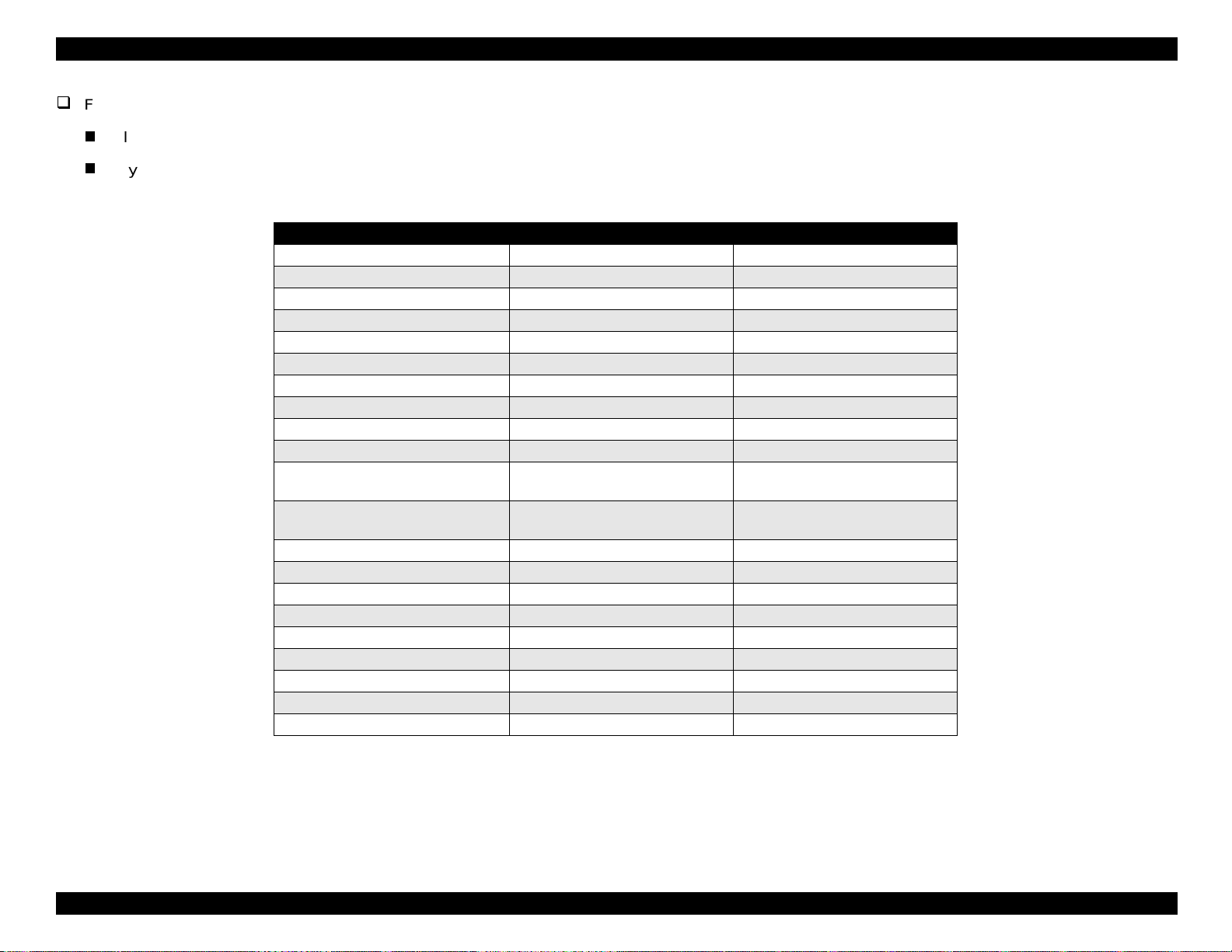
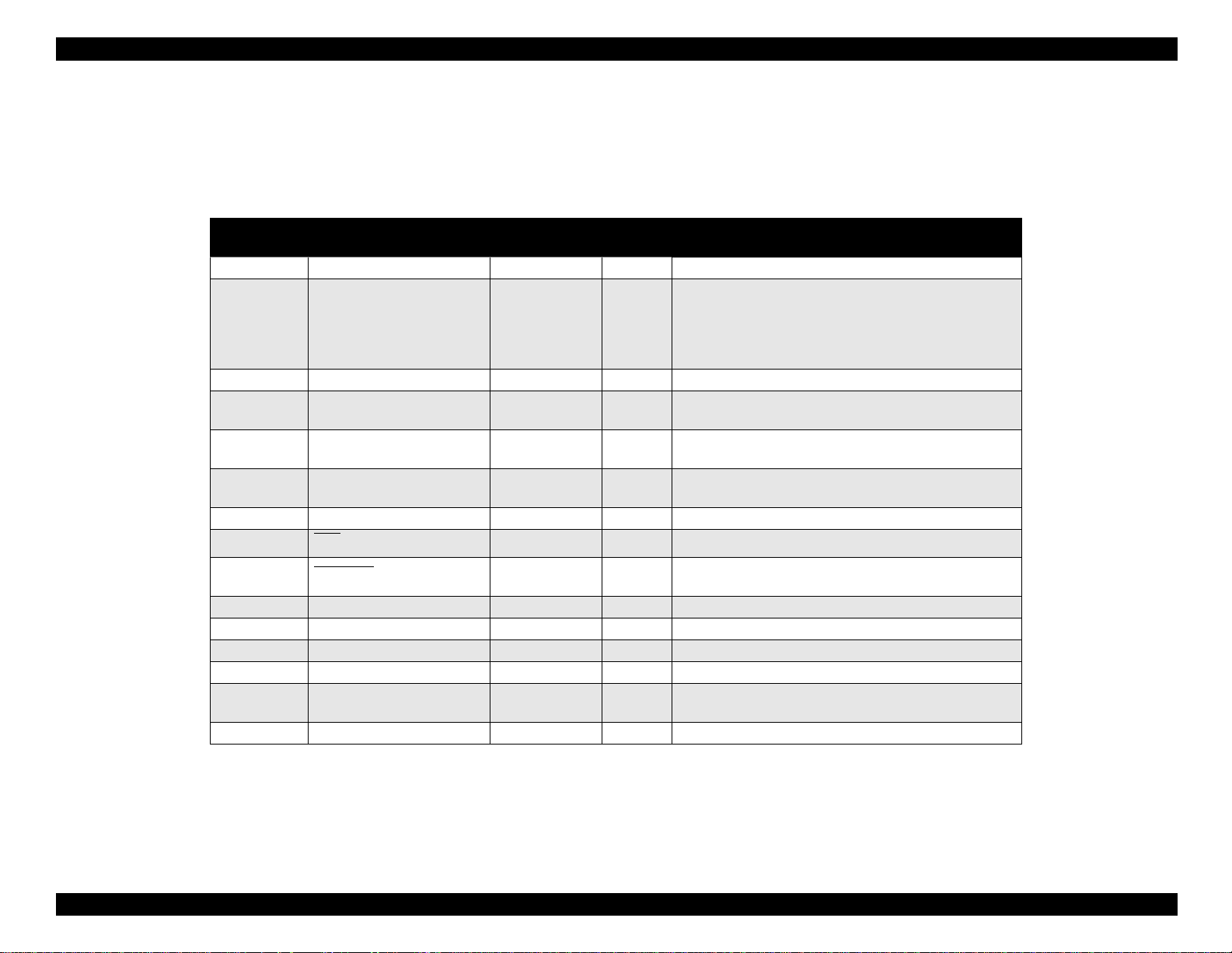
Table 1-1. Consumables Available for Stylus Color 440/640/740
Items Codes Remarks
Black ink cartridge S020189 Stylus Color 740
Black ink cartr idge S020187 Stylus Color 440, 640
CMY ink cartridge S020191 Stylus Color 440, 640, 740
EPSON 360 dpi ink jet paper S041025 Size: A4 (200 sheets )
EPSON 360 dpi ink jet paper S041059 Size: A4 (100 sheets)
EPSON 360 dpi ink jet paper S041060 Size: Letter (100 sheets)
Photo quality ink jet paper S041026 Size: A4 (200 sheets)
Photo quality ink jet paper S041061 Size: A4 (100 sheets )
Photo quality ink jet paper S041062 Size: Letter
Photo quality ink jet paper S041067 Size: Legal
Photo quality glossy paper (new
release)
Photo quality glossy paper (new
release)
Photo quality glossy film S041071 Size: A4
Photo quality glossy film S041124 Size: Letter
Photo quality glossy film S041107 Size: A6
Ink jet transparencies S041063 Size: A4
Ink jet transparencies S041064 Size: Letter
Photo quality ink jet cards S041054 Size: A6
Photo quality ink jet cards S041121 Size: 5 x 8 inches
Photo quality ink jet cards S041122 Size: 8 x 10 inches
Photo quality self-adhesive sheets S041106 Size: A4
S041126 Size: A4
S041124 Size: Letter
3
Page 13
EPSON Stylus COLOR 440, 640, and 740 Chapter 1 Product Description
g
g
y
j
)
g
g
g
y
)
y
)
y
)
1.2 Specifications
Nozzle Confi
urations:
This section provide s th e f ollowing information for all three printers:
printin
settin
specifica t ions, reliabilit
specifica ti ons , paper specif ic ations, pri nt able area, a djust lever
s, ink cartridge specific at ions, enviro nm ental conditions, el ec t ric
statistics, safety approvals, and CE marking.
1.2.1 Printing Specifications
Print method
On-demand ink
color heads
Print direc t ion
Bidirecti onal with lo
Print spee d/ Printable co lum ns
Table 1-2. Character Mode Speed
Model Name
Stylus COLOR 440 10 80 200 CPS —
Stylus COLOR 640 10 80 200 CPS 400 CPS
Stylus COLOR 740 10 80 200 CPS —
et (MACH type; one unit c om bining black an d
ic seekin
Character
Pitch
Printable
Columns
LQ Speed Draft Speed
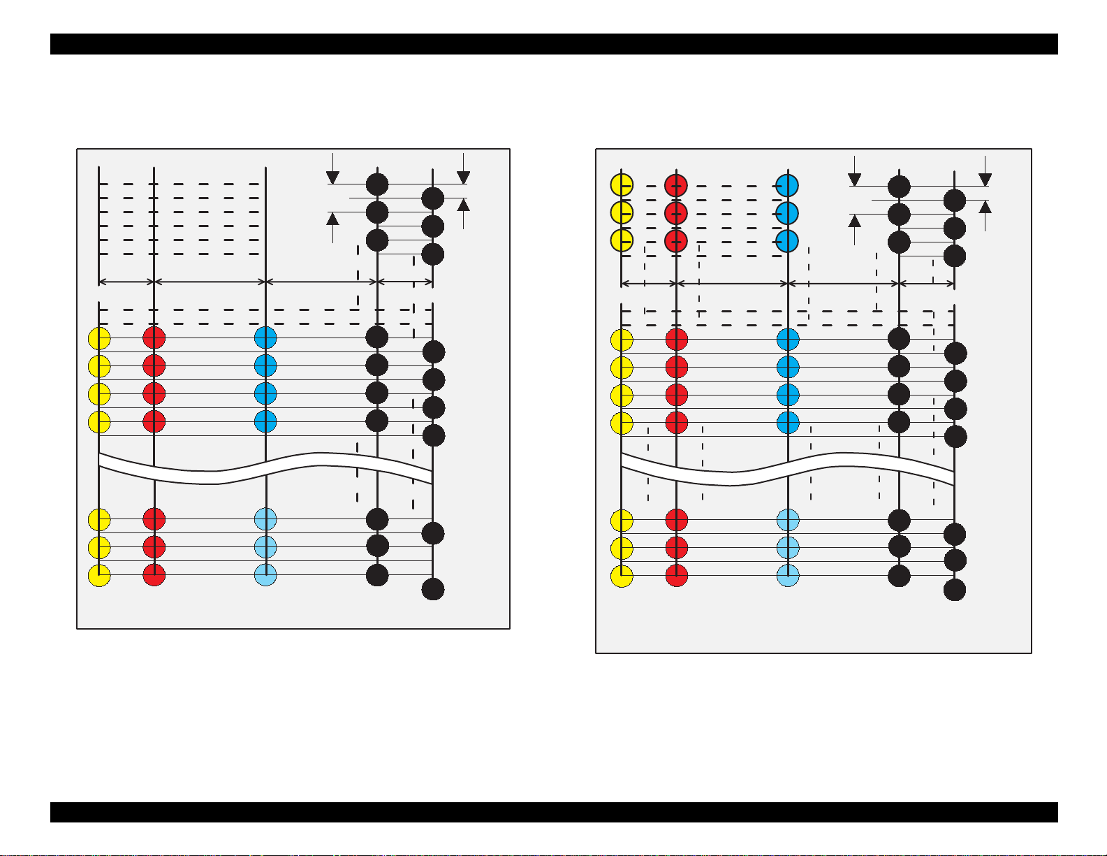
lus COLOR 440 (see Figure 1-1):
St
Black— 64 nozzles
×
Color—21 nozzles
St
lus COLOR 640 (see Figure 1-2):
3 (CMY
Black— 64 nozzles
×
Color—32 nozzles
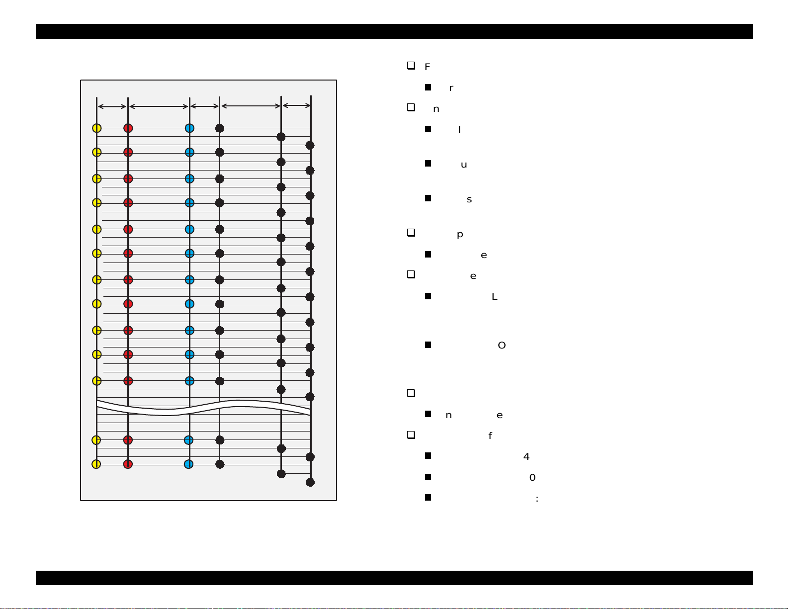
St
lus COLOR 740 (see Figure 1-3):
3 (CMY
Black— 144 nozzles
Color—48 nozzles × 3 (CMY
Table 1-3. Graphic Mode Speed
Horizontal
Resolution
180 dpi 8.26 1488 20 IPS
360 dpi 8.26 2976 20 IPS
720 dpi 8.26 5952 20 IPS
Printable Area Available dots CR Sp eed
4
Page 14
EPSON Stylus COLOR 440, 640, and 740 Chapter 1 Product Description
Y1
Y2
Y3
Y4
Y19
Y20
Y21
M 1
M 2
M 3
M 4
M 19
M 20
M 21
#1
90DPI
#3
#5
10.16 mm2.2578 mm
7.9022 mm
C1
C2
C3
C4
C19
C20
C21
#23
#25
#27
#29
#59
#61
#63
#2
#4
#6
2.2578 mm
#24
#26
#60
#62
#64
180DPI
Y1
Y2
Y3
2.2578 mm
Y12
Y13
Y14
Y15
Y30
Y31
Y32
M1
M2
M3
10.16 mm
M12
M13
M14
M15
M30
M31
M32
C1
C2
C3
7.9022 mm
C12
C13
C14
C15
C30
C31
C32
90DPI
#1
#3
#5
#23
#25
#27
#29
#59
#61
#63
#2
#4
#6
2.2578 mm
#24
#26
#60
#62
#64
180DPI
(Y)
(M)
(C)
(B2)
(B1)
Figure 1-1. Nozzle Configuration for the Stylus COLOR 440
(Y)
(M)
(C)
(B2)
(B1)
Figure 1-2. Nozzle Configuration for the Stylus COLOR 640
5
Page 15
EPSON Stylus COLOR 440, 640, and 740 Chapter 1 Product Description
(
)
g
y
y
y
y)
y
(
(
y
g
(
y
g
)
y
y
y
Feed method
32/360"
#1
#2
#3
#4
#5
#6
#7
#8
#9
#10
#11
112/360"
#1
#2
#3
#4
#5
#6
#7
#8
#9
#10
#11
32/360"
#1
#2
#3
#4
#5
#6
#7
#8
#9
#10
#11
112/360"
#1
#4
#7
#10
#13
#16
#19
#22
#25
#28
#31
32/360"
#2
#5
#8
#11
#14
#17
#20
#23
#26
#29
#32
#3
#6
#9
#12
#15
#18
#21
#23
#26
#29
#32
Line spac in
Paper path
Feed speed
Ink suppl
Friction feed with the ASF
St
lus COLOR 440: 1/6 inch, or programmab le in units of 1/360
Automatic Sheet Feeder
inch
St
lus COLOR 640: 1/6 inch, or programmab le in units of 1/360
inch
St
lus COLOR 740: 1/6 inch, or programmab le in units of 1/360
inch
Cut-sheets: ASF (top entr
lus COLOR 440 and 640:
St
190 ms per 1/3-inch
2.0 in/sec
lus COLOR 740
St
50.8 mm/sec), continuous
110 ms, advancin
4.5 in/sec
114.3 mm/sec), continuous
8.5-mm) increme nt advance
in 0.4-inch (10.16-mm) increm ents
#47
#48
Ink cartrid
#47
#48
(M)(Y)
#47
#48
(C)
(B1)
#139
#142
(B2)
#140
#143
(B3)
#141
#144
Input da ta buffer
St
lus COLOR 440: 10 Kb
St
lus COLOR 640: 32 Kb
St
lus COLOR 740: 64 Kb
es (Black an d C M Y
Figure 1-3. Nozzle Configuration for the Stylus COLOR 740
6
Page 16
EPSON Stylus COLOR 440, 640, and 740 Chapter 1 Product Description
y
y
g
y
(
(
g
y
y
y
(
)
(
)
y
(
(
(
Paper capacit
Size: Index card to L e
Thickness: Less than 8 mm
Paper capacit
Photo Paper, Iron-On Cool Pee l
Character tables:
St
lus COLO R 440 and 640
PC437
of input tra
: 100 cut sheets
10 envelopes
65 sheets of c oated pape r
65 sheets of c oated pape r
lossy sheets or sheets of EPSON Photo
20
Paper
30 transparency sheets
30 index cards
1 sheet of an
Transfer Paper, Pho to St ic k ers ,
Gloss
Film, Self Ad hesive Paper
US, Standard Europe
al
360 dpi)
720 dpi)
of the follow ing: Panoramic
St
lus COLOR 740
Standard version: 11 charac t er t ables
Italic, PC437
PC860
US Standard, Europe), PC850 (Multilingual),
Portuguese), PC861 (Iceland ic), PC863
Canadian-French), PC865 (Nordic), Abicomp, BRASC I I,
Roman 8, IS O Latin 1
NLSP v ers ion: 30 charac t er t ables
Italic, PC437, PC437 Greek , P C 850, PC852, PC 853,
PC855, PC857, PC860, PC861, PC865, PC866, ISO8859-7,
ISO Lat in 1T , PC 774, Esto nia, ISO8859-2, PC866-LAT,
PC866UKR, PC AR864, PC APTEC, PC708, PC720,
Hebrew7
*
, Hebrew8*, PC862
*
NOTE: Character t ables mark ed with an asterisk are not av ailable for
selection in the default setting mode.
PC850
Multilingual
NOTE: Thes e c haracter se ts are not available for selection in th e
default set t ing mode.
7
Page 17

EPSON Stylus COLOR 440, 640, and 740 Chapter 1 Product Description
y
y
y
g
(
)
)
)
)
y
y
(
g
(
)
)
)
)
(
)
(
)
(
)
)
T
pefaces
1.2.2.1 Cut Sheets
lus COLO R 440 and 640
St
Bitmap LQ fo nt : EPSON Courier 10 cpi
lus COLO R 740
St
Bitmap LQ fo nt s :
EPSON R om an 10 cpi, 12 cpi, 15 cpi, Pro portional
EPSON Sans Serif 10 cpi, 12 cpi, 15 cpi, Pro portional
EPSON C ourier 10 cpi, 12 cpi, 15 cpi
EPSON Presti
e 10 cpi, 12 cpi, 15 cpi
EPSON Sc ript 10 cpi, 12 cpi , 15 cp i
Scalable f onts:
EPSON Roman 10.5 pt.; 8 to 32 pt.
2 pt. increments
EPSON Sans Serif 10.5 pt.; 8 to 32 pt. (2 pt. increments
EPSON Roman T 10.5 pt.; 8 to 32 pt. (2 pt. increments
EPSON Sans Serif H 10. 5pt.; 8 to 32 pt. (2 pt. increments
NOTE: Each t yp ef ace has 4 va riat ions: Normal, Bold, Italic, and Bold
Italic.
Control codes
St
lus COLO R 440 and 640
ESC/P raster
EPSON remote commands
Sizes
Letter: Width 8 .5 ”
Le
al: Width 8.5”
216 mm) x Length 11.0” (279 mm)
216 mm) x Length 14.0” (356 mm
Statement: Width 5 .5 ” (139.7 mm) x Length 8.5” (216 mm
Exclusiv e: Width 7.5” (190.5 mm) x Length 10” (254 mm
A4: Width 8.3” (210 mm) x Length 11.7” (297 mm
B5: Width 7.2”
182 mm) x Length 10.1” (257 mm
Thickness
0.003”
0.08 mm) to 0.004” (0.11 mm
Weight
17 lb
64 g/m
2
to 24 lb (90 g/m
2
Quality
EPSON paper, bon d paper, or PPC
St
lus COLO R 740
ESC/P2 and ESC/P raster
EPSON remote commands
1.2.2 Paper Specifications
This section describes the printable area and types of p aper th at c an be
used with t hes e printers.
8
Page 18

EPSON Stylus COLOR 440, 640, and 740 Chapter 1 Product Description
(
)
)
(
)
(
)
)
)
(
)
(
)
)
(
)
)
)
)
(
)
1.2.2.2 Transparencies, Glossy Paper
Sizes
Letter: Width 8.5”
216 mm) x Length 11.0” (279 mm
A4: W idth 8.3” (210 mm) x Length 11.7” (297 mm
Thickness
0.003”
0.075 mm) to 0.0033 ” (0.085 mm
NOTE: Printing on transparencie s is available only at normal
temperatures.
1.2.2.3 Envelopes
Sizes
No.10 Width 9.5”
DL Width 8.7” (220 mm) x Length 4.3” (110 mm
C6 Width 6.4” (162 mm) x Length 4.5” (114 mm
Thickness
241 mm) x Length 4.13” (104.88 mm
1.2.2.4 Card Stock
Sizes
5 x 8” card: Width 5.0”
8 x 10” car d: Width 8.0 ” (203 mm) x Length 10.0” (254 mm
A6 card: Width 4.1” (105 mm) x Length 5.8” (148 mm
A5 card: Width 5.8” (148 mm) x Length 8.3” (210 mm
Thickness
Less than 0.0091”
0.23 mm
127 mm) x Length 8.0” (203 mm
0.006”
0.16 mm) to 0.02” (0.52 mm
Weight
12 lb
45 g/m
2
to 20 lb (75 g/m
2
Quality or Paper Type
Bond paper envelopes, plain paper envelopes, or air mail envelopes
NOTES:
1. Printing on enve lopes is avail able only at normal temp eratures.
2. Load the longer side of the envelop e horizontally.
9
Page 19
EPSON Stylus COLOR 440, 640, and 740 Chapter 1 Product Description
g
g
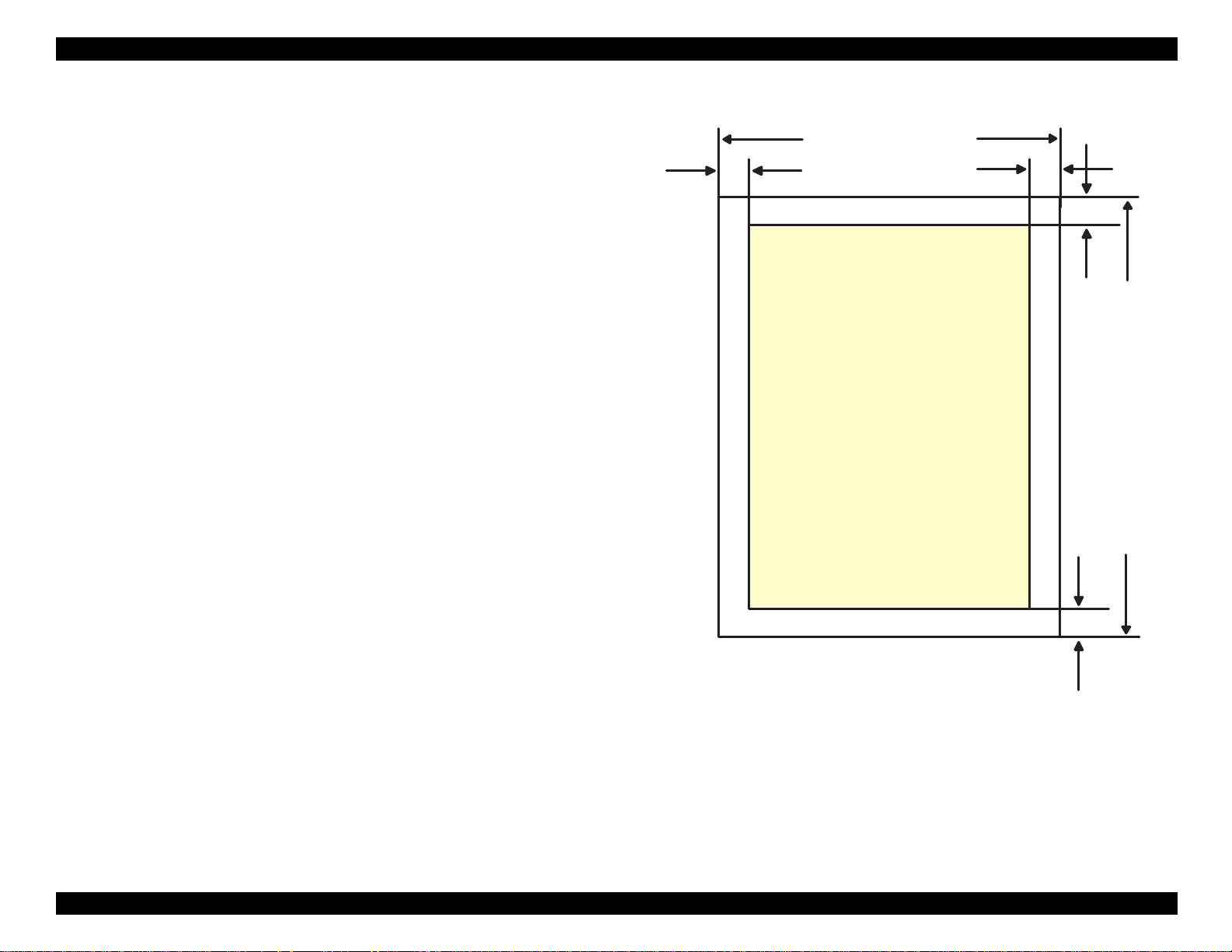
1.2.3 Printable Are a
Cut Sheets
ure 1- 4 in th e right column and the tables on the following page show
Fi
printable areas in character mo de and raster
NOTE: Charac t er mode is su pported on ly by th e St y lus COLOR 740.
raphics mode.
LM
PW
Printable
Area
RM
TM
PL
BM
Figure 1-4. Printable Area for Cut Sheets
10
Page 20
EPSON Stylus COLOR 440, 640, and 740 Chapter 1 Product Description
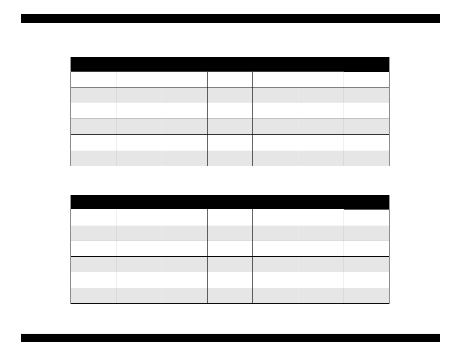
Table 1-4. Raster Graphics Mode
Paper Size PW (Typical
Paper Width)
A4 8.3” (210 mm) 11.7” (297 mm) 0.12” (3 mm) 0.12” (3 mm) 0.12” (3 mm)
Letter 8.5” (216 mm) 11.0” (279 mm) 0.12” (3 mm) 0.35” (9 mm) 0.12” (3 mm)
B5 7.2” (182 mm) 10.1” (257 mm) 0.12” (3 mm) 0.12” (3 mm) 0.12” (3 mm)
Legal 8.5” (216 mm) 14.0” (356 mm) 0.12” (3 mm) 0.35” (9 mm) 0.12” (3 mm)
Statement 5.5” (139.7 mm) 8.5” (21 6 mm) 0.12” (3 mm) 0.12” (3 mm) 0.l2” (3 mm)
Executive 7.5” (190.5 mm) 10”(254 mm) 0.12” (3 mm) 0.12” (3 mm) 0.12” (3 mm)
PL (Typical
Paper Length)
LM (Minimum
Left Margin)
RM (Minimum
Right Margin)
TM (Minimum
Top Margin
BM (Minimum
Bottom Margin)
0.54” (14 mm)
0.12” (3 mm)
0.54” (14 mm)
0.12” (3 mm)
0.54” (14 mm)
0.12” (3 mm)
0.54” (14 mm)
0.12” (3 mm)
0.54” (14 mm)
0.12” (3 mm)
0.54” (14 mm)
0.12” (3 mm)
Table 1-5. Character Mode (Stylus COLOR 740 only)
Paper Size PW (Typical
Paper Width)
A4 8.3” (210 mm) 11.7” (297 mm) 0.12” (3 mm) 0.12” (3 mm) 0.12” (3 mm)
Letter 8.5” (216 mm) 11.0” (279 mm) 0.12” (3 mm) 0.35” (9 mm) 0.12” (3 mm)
B5 7.2” (182 mm) 10.1” (257 mm) 0.12” (3 mm) 0.12” (3 mm) 0.12” (3 mm)
Legal 8.5” (216 mm 14.0” (356 mm) 0.12” (3 mm) 0.35” (9 mm) 0.12” (3 mm)
Statement 5.5” (139.7 mm) 8.5” (216 mm) 0.12” (3 mm) 0.12” (3 mm) 0.12” (3 mm)
Executive 7.5” (190.5 mm) 10” (254 mm) 0.12” (3 mm) 0.12” (3 mm) 0.12” (3 mm)
PL (Typical
Paper Length)
LM (Minimum
Left Margin)
RM (Minimum
Right Margin)
TM (Minimum
Top Margin)
BM (Minimum
Bottom Margin)
0.54” (14 mm)
0.12” (3 mm)
0.54” (14 mm)
0.12” (3 mm)
0.54” (14 mm)
0.12” (3 mm)
0.54” (14 mm)
0.12” (3 mm)
0.54” (14 mm)
0.12” (3 mm)
0.54” (14 mm)
0.12” (3 mm)
11
Page 21

EPSON Stylus COLOR 440, 640, and 740 Chapter 1 Product Description
y
y
(
g
Envelopes
Table 1-6 and Figure 1-5 show t he printable area for envelopes.
Table 1-6. Printable Area for Envelopes
Envelope
Size
#10 0.12” (3 mm) 1.10” (28 mm) 0.12” (3 mm)
DL 0.12” (3 mm) 0.28” (7 mm) 0.12” (3 mm)
C6 0.12” (3 mm) 0.12” (3 mm) 0.12” (3 mm)
LM (Minimum
Left Margin)
LM
RM (Minimum
Right Margin)
TM (Minimum
Top Margin)
BM (Minimum
Bottom Margin)
0.54” (14 mm)
0.12” (3 mm)
0.54” (14 mm)
0.12” (3 mm)
0.54” (14 mm)
0.12” (3 mm)
RM
Printable
Area
TM
BM
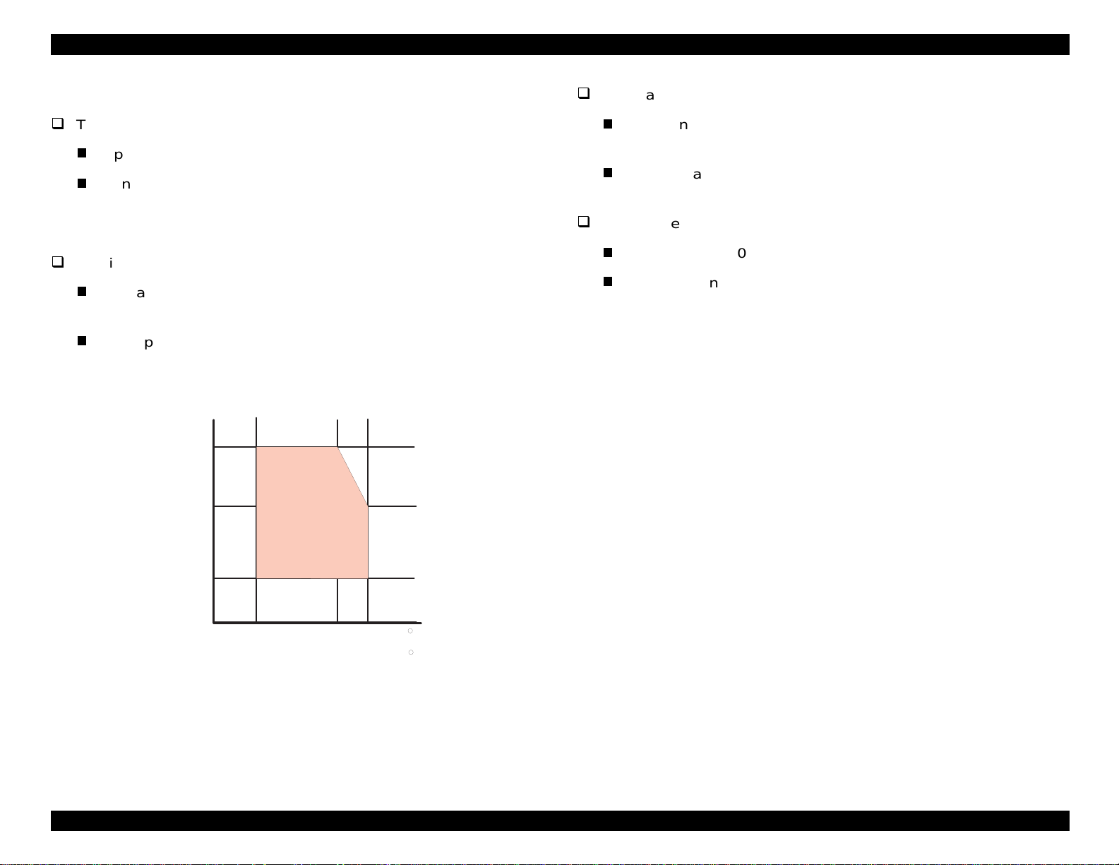
1.2.3.1 Adjust Lever Setting (PG Adjust Lever)
The adjust lever (blue) on the right side under the printer cover needs to
be set to the proper position for the paper
If
ou find th at th e paper wrin k les during printing, or if smudges appear
on the paper, move the lever to the + position
ardless of paper type.
re
Table 1-7. Adjust Lever Setting
Lever Position Clearance between head and platen
Plus position 1.04 mm
Zero position 1.74 mm (+0.7 mm)
NOTE: A lw ays return th e adjust leve r to th e z ero position af t er you
finish printing. Leaving the lever in the plus position may cause
poor pri nt ing in the next printout.
ou pri nt on. (See Tabl e 1 -7.)
toward the rear),
Figure 1-5. Printable Area for Envelopes
12
Page 22

EPSON Stylus COLOR 440, 640, and 740 Chapter 1 Product Description
18.3
38.5
51.2
19.8
52.7
27.8
52.7
38.5
51.2
26.3
18.3
38.5
51.2
19.8
52.7
for S tylus C olor 440, 640
for S tylus C olor 740
1.2.4 Ink Cartridge Specifications
Black Ink Cartridge
Table 1-8. Black Ink Cartridge Specifications
Items Specifications
Type Exclusive EPSON ink cart ridges designed for the Stylus COLOR
440, 640, and 740
Print c apa c ity • Stylus COLOR 440 and 640
-540 pages / letter or A4 (ISO/IEC 10561 Letter Patt ern at
360 dpi)
Cartridge life 2 years (sealed in package) / 6 months (out of package)
Environmental
conditions
Dimensions •
Weight Cartridge plus ink: 1.06 oz (30 g)
• Stylus COLOR 740
- 900 pages / letter or A4 (ISO/IEC 10561 Letter Pattern at
360 dpi)
• Temperature
- Storage: -4 to 104 °F (-20 to 40 °C)
1 month at 104 °F (40 °C)
- Packing stora ge: -22 to 104 °F (-30 to 40 °C)
1 month at 104 °F (40 °C)
- Transit: -22 to 140 °F (-30 to 60 °C)
1 month at 104 °F (40 °C)
120 hours at 140 °F (60 °C)
• Humidity
5% to 85% (without condensation)
Note:
Ink freezes bel ow 27 °F (-3 °C) but it thaws and is usable after 3
hours at 77 °F (25 °C).
Stylus COLOR 440 and 640
0.78” W × 2.1” D × 1.52” H (19.8 mm W × 52.7 mm D ×
38.5 mm H)
Stylus COLOR 740
•
1.09” W × 2.1” D × 1.5” H (27.8 mm W × 52.7 mm D ×
38.5 mm H)
Total ink: 0.58 oz +/- 0. 02 oz (16. 4 +/-0.5 g)
Consumable ink weight: more than 0.43 oz (12.1 g)
Figure 1-6. Black Ink Cartridge Dimensions (units in mm)
13
Page 23

EPSON Stylus COLOR 440, 640, and 740 Chapter 1 Product Description
Color Ink Cartridge
Table 1-9. Color Ink Cartridge Specifications
Items Specifications
Type Cartridge especially designed for the Stylus COLOR 440, 640
and 740
Colors Cyan, Magenta, Yellow (CMY)
Print capacity 300 pages / A4 (360 dpi, 5% duty each color)
Cartridge life 2 years (sealed in package) / 6 months (out of package)
Environmental
conditions
• Temperature
- Storage: -4 to 104 °F (-20 to 40 °C)
1 month at 104 °F (40 °C)
- Packing storage: -22 to 104 °F (-30 °C to 40 °C)
1 month at 104 °F (40 °C)
- Transit: -22 to 140 °F (-30 °C to 60 °C)
1 month at 104 °F (40 °C)
120 hours at 140 °F (60 °C)
•Humidity
5% to 85% (without condensation)
Note:
Ink freezes below 27 °F (-3 °C), but it thaws and i s usable after 3
hours at 77 °F (25 °C).
• Dimensions
×
1.7” W
2.1” D × 1.5” H (42.9 mm W × 52.7 mm D ×
38.5 mm H)
Weight Cartridge plus ink: 2.36 oz (67 g)
Total ink: 0.45 oz +/- 0. 02 oz (12. 8 +/-0.5 g)
Consumable ink weight: mo re than 0.34 oz (9.6 g)
52.7
42.9
41.4
43.2
51.2
38.5
Figure 1-7. Color Ink Cartridge Dimensions (units in mm)
14
Page 24
EPSON Stylus COLOR 440, 640, and 740 Chapter 1 Product Description
g
g
y
g
(
)
g
g
g
g
g
)
1.2.5 Environmental Conditions
Resistance to shock
Temperature
Operatin
Non-operatin
: 50 to 95 °F (10 to 35 °C) (See Figure 1-8.)
:-4 °F to 140 °F (-20 to 60 °C) in shipme nt
containe r
NOTE: 1 month at 104 °F (40 °C) an d 120 hour s a t 1 40 °F (60 °C)
Humidit
Operatin
: 20% to 80% RH without condensation
See Figure 1-8.
Non-operatin
shippin
: 5% to 85% RH without condensation and in
container
Hum idity
(% R H )
80%
55%
20%
G uaranteed
A re a
Operatin
: 1 G, within 1 ms
X, Y, and Z directions
Non-operatin
: 2 G, within 2 ms
X, Y, and Z directions, in shipment c ontainer
Resistance to vibration
Operating:0.15 G
Non-operatin
:0.50 G
NOTES: 1. When the printer is not in operation , ma k e s ure that the
printhead is capped.
2. During transport, make s ure the printhead is capped and
the ink cartridges are installed.
3. If you notice that the printhead is not capped while power
is off, turn power on (in k ca rt ridges should be installed).
After the printhead has moved to the capping position,
turn pow er off again.
4. Ink freezes under 27 °F (-3 °C), but thaws and becomes
usable again after 3 hours at 77 °F (25 °C).
10 27
50
35
80 95
( C
( F )
Figure 1-8. Temperature / Humidity of Range
15
Page 25

EPSON Stylus COLOR 440, 640, and 740 Chapter 1 Product Description
g
g
q
q
(
)
)
(
)
(
)
g
g
q
q
(
)
)
(
)
(
)
)
)
)
y
y
y
)
g
1.2.6 Electrical Specifications
120 V Versi o n
Rated volta
Input volta
Rated fre
Input fre
Rated current: 0.4 A
Power co ns um ption: Approxim ately 16 W (ISO/IEC 10561
Insulation resistan c e: 10M ohms minimum
Dielectric s tr ength: 1000 VAC rms for 1 minute or 1200 VAC rms
220 to 240V Version
Rated volta
Input volta
Rated fre
Input fre
Rated current: 0.2 A
Power co ns um ption: Approxim ately 16 W (ISO/IEC 10561
Insulation resistan c e: 10M ohms minimum
Dielectric s tr ength: 1500 VAC rms for 1 minute
e: 120 VAC
e range: 99 to 132 VAC
uency range: 50 to 60 Hz
uency range: 49.5 to 60.5 Hz
maximum 0.5 A
Letter patt ern
between AC line and chassis, 500 VDC
for 1 second
e: 220 to 24 0 VAC
e range: 19 8 t o 264 VAC
uency range: 50 to 60 Hz
uency range: 49.5 to 60.5 Hz
maximum 0.3 A
Letter patt ern
500 VDC bet w een AC line and chassis
betwee n AC line and cha s s is
; ENERGY STAR-c ompliant
between AC line and chassis
; ENERGY STAR-c ompliant
1.2.7 Reliability
Total Print Volume
Stylus COLO R 440: 10,000 pages (A4, Letter
Stylus COLO R 640: 25,000 pages (A4, Letter
Stylus COLO R 740: 75,000 pages (A4, Letter
Printhead Life
Stylus COLOR 440: 2x10⁹ dots/nozzle
St
lus COLOR 640: 2x10⁹ dots/nozzle
lus COLOR 740: 4x10⁹ dots/nozzle
St
1.2.8 Sa fe ty App r ov als
120 V Version
Safety standards UL1950 with D3
CSA22.2 No.950 with D3
EMI FCC part 15 subpart B class B
CSA C108.8 class B
220 to 240 V Version
Safet
EMI EN55022 (CISPR Pub.22) class B
standard s EN 60950 (VDE, NEMKO
AS/NZS 3548 class B
1.2.9 CE Ma rk in g
220 to 240 V Version
Low Volt a
EMC Directive 89/336/EEC: EN55022 Class B
e Directiv e 73/23/EEC :EN60950
EN61000-3-2
EN61000-3-3
EN50082-1
IEC801-2
IEC801-3
IEC801-4
16
Page 26

EPSON Stylus COLOR 440, 640, and 740 Chapter 1 Product Description
y
(
g
g
g
g
(
)
(
)
j
g
g
g
1.3 Interface Specifications
A parallel int erf ace is standard on all th ree printers.
1.3.1 Parallel Interface (Forward Channel)
Transmission mode
Synchronization
Handshaking
Signal level
Adaptable connector
The BUSY si
h, and rem ains high until the s e s ignals ret urn to their inac t iv e s t at e.
hi
The BUSY si
Durin
When the input data buffer is full
When the INIT
nal is set high before setting either ER R OR low or PE
nal is HIGH at these times:
data entry
8-bit parallel, IEEE-1284 compatibilit
STROBE pu lse
BUSY and ACKLG
TTL-com patible le ve l
57-30360
signal is LOW , or during hardware initializat ion
Amphenol) or equivalent
signals
mode
Table 1-10
assi
line is used and the return side is connected to the GND si
on the follo w ing page shows the signal and connector pin
nments for the parallel interface. With these signals, a twiste d pair
nal.
NOTE: The forward channel is the mode used to send ordinary da ta ,
such as w hen a print com m and is sent fr om t he compute r t o
the print er.
When the re is a printer erro r
The ERROR signal is LOW w hen the printer is in one of th e f ollowing
states.
The PE si
Printer hardware error
Paper-o ut error
PaperInk-out error
am error
nal is HIGH during a paper-out error.
fatal err or
See ERROR signal
17
Page 27
EPSON Stylus COLOR 440, 640, and 740 Chapter 1 Product Description
Table 1-10. Signal and Connector Pin Assignments for the Parallel Interface
Pin No.
1STROBE
2 to 9
10 ACKNLG
11 BUSY 29 Out
12 PE 28 Out
13 SLCT 28 Out
14 AFXT
31 INIT 30 In
32 ERROR
36 SLIN 30 In Not used.
18 Logic-H — Out Pulled up to +5 V via 3.9K ohm resistor.
35 +5V — Out Pulled up to +5 V via 3.3K ohm resistor.
17
16,33,
19 to 30
15,34 NC — — Not connected.
Signal
Name
DAT A0 t o
DAT A7
Chassis
GND
GND — — Signal ground.
Notes: In and Out refer to the direction of signa l f low f rom the printer’s poi nt of view.
An overscore above a signal name means that the signal is active LOW.
Return
GND Pin
19 In
20 to 27 In
28 Out
30 In Not used.
29 Out
— — Chassis ground.
In/Out Functional Descri ption
The strobe pulse. Data is re ad in at the
falling edge of this pulse.
The DATA0 through DATA7 signals
represent data bits 0 thr ough 7. Each
signal is at a HIGH level when dat a is
logical 1, and at a LOW level when data
is logical 0.
This signal is a negative pulse indicating
that the printer can agai n accept data.
A HIGH signal indicates that the printer
cannot receive data.
A HIGH signal indicates a paper-out
error.
Always HIGH when the printer is
powered on.
The falling edge of a negati ve pulse or a
LOW signal on this line causes the
printer to initialize . Mini mum 50
is necessary.
A LOW signal indicates a printer error
condition.
µ
s pulse
18
Page 28

EPSON Stylus COLOR 440, 640, and 740 Chapter 1 Product Description
(
y
y
q
g
1.3.2 Parallel Interface (Reverse Channel)
Transmission mode:
Synchronization:
Handshaking:
Data transmission timing:
Signal level:
Adaptable connector:
Extensi b ili ty r eq u est:
IEEE-1284 nibble m ode
Refer to th e IE EE-1284 s pecification
Refer to th e IE EE-1284 s pecification
Refer to th e IE EE-1284 s pecification
IEEE-1284 level 1 device
TTL-compatible level
57-30360
Amphenol) or equivalent
The printe r responds af f irm ativel
the extens ibilit
request values are 00H or
04H, which means:
00H: Request nibb le m ode reverse
channel t ransfer.
04H: Re
uest device ID; return data
usin
nibble mode reverse
channel t ransfer.
when
NOTE: The printer se nds followin g device ID string when requested.
Table 1-11. Details of Device ID
00H 3CH Contents
MGF EPSON Manufacturer
CMD ESCPL2, BDC Command system
Stylus COLOR 440
MDL
CLS PRINTER Class
Stylus COLOR 640
Stylus COLOR 740
Model name
NOTES: 1. [00H] denotes a hexadecimal value of zero.
2. The MDL value depends on the EEPROM setting. The
model name can be c hanged by ch anging an address in
the EEPR OM.
19
Page 29
EPSON Stylus COLOR 440, 640, and 740 Chapter 1 Product Description
g
Table 1-12 shows pin as s ignments for the reverse channel. (Reverse
channel is th e m ode in which all data is tra ns f erred from th e printer to
the comput er.) For these signals, a twist ed pair line is us ed, and the
return sid e is co nnected to th e s i
nal GND .
Table 1-12. Pin Assignments for Reverse Channel
Pin No. Signal Name
1 HostClk 19 In Host clock signal.
2 to 9 Data0 to Data7 20 to 27 In
10 PrtClk 28 Out Printer clock signal.
11 PtrBusy, Data Bit-3,7 29 Out
12 AckData Req, DataBit-2,6 28 Out
13 Xflag, DataBit-1,5 28 Out
14 HostBusy 30 In Host busy signal.
31 INIT 30 In
32 DataAvail
36 1284-Active 30 In 1284 Active Signal
18 Logic-H — Out Pulled up to +5 V via 3.9K ohm resistor.
35 +5 V — Out Pulled up to +5 V via 3.3K ohm resisto r.
17 Chassis GND — — Chassis ground.
16,33, 19 to
30
15,34 NC — — Not connected.
Notes: In/Out ref ers to the direction of signal flow from the printer’s point of view.
An overscore above a signal name means that signal is active LOW.
GND — —
, DataBit-0,4 29 Out
Return GND
Pin
In/Out Functional Description
The DATA0 through DATA7 signals represent data
bits 0 through 7. Each signal is at HIGH level when
data is logical 1, and at a LOW level when data is
logical 0. These signal s are used to transfer th e 1284
extensibility request valu es to the printer.
Printer busy signal and reverse channel tra nsfer data
bit 3 or 7.
Acknowledge data request signal and revers e channel
transfer data bit 2 or 6.
X-flag signa l and reverse channel tran sfer data bit 1 or
5.
Not used.
Data available signal and reverse channel tr ansfer
data bit 0 or 4.
Signal ground.
20
Page 30
EPSON Stylus COLOR 440, 640, and 740 Chapter 1 Product Description
g
(
y
g
g
g
y
g
g
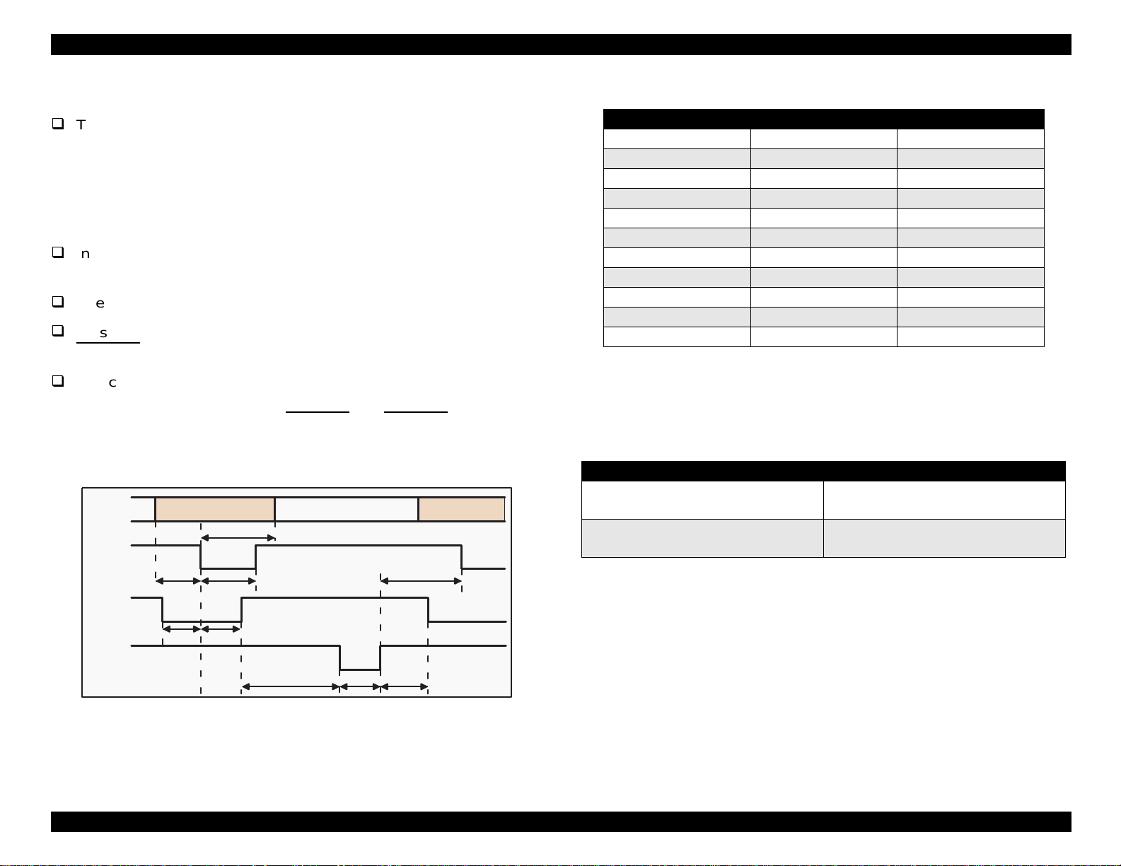
The following are general notes on the parallel interface:
The Return GND Pin c olumn in Tables 1-10 an d 1-12 indica t es a
twisted pair return, and is used for all control si
nals exce pt Logic-H,
+5 V, Chassis GND, and NC. The return side is connected to GND
pins 16, 33 , and 19 to 30) in the twisted pair retu rn. Since thes e
cables are s hielded,
connectin
Interface conditions are based on TTL lo
them to Chassis GND in both the printer and computer.
should be less than 0.2
See Fi
Be sure to perform data transmission onl
ACKNLG
You can perform a print t es t wi th out usin
ure 1-9 for the transmission timing of each signal.
and BUSY s ignals are LOW.
the 8-bit da t a s i
code and connect them to the ACKNLG
Data
/STROBE
Tsetup
BUSY
ou can reduce electrostatic noise by
ic levels. Rise and fall ti mes
µ
s.
after conf irm ing that the
external equipment. Set
nals (pins 20 th rough 27) to the appro priate word
and STRO BE signals.
Byte Data n
Thold
Tstrb
Byte Data n+1
Tnext
Maximum and Minimum Timing for Data Transmission
Parameter Minimum Maximum
tsetup 500ns —
thold 500ns —
tstb 500ns —
tready 0 —
tbusy — 500ns
tt-out* — 120ns
tt-in** — 200ns
treply 0 —
tack 500ns 10us
tnbusy 0 —
tnext 0 —
* Rise and fall time of every output signal.
** Rise and fall time of every input signal. Typical timing for the tack
paramete r is s how n in Table 1 -14 below.
Table 1-14. Typical Tack Timing
Parallel Interface Mode Typical Tack Timing
µ
2
High speed
Normal speed
s (Stylus COLOR 440 and 640)
µ
s (Stylus COLOR 740)
1
4µs (Stylus COLOR 440 and 640)
µ
s (Stylus COLOR740)
3
/ACKNLG
Tready Tbusy
Treply
Tack Tnbusy
Figure 1-9. Data Transmission Timing for the Forward Channel
Table 1-13.
21
Page 31

EPSON Stylus COLOR 440, 640, and 740 Chapter 1 Product Description
(
y
y
y
y
y
g
(Sty
g
y
g
g
g
q
g
g
g
g
The following tables show typical input and output signal levels for the
interface
IEEE-1284 lev el 1 devi c e). Signal levels are based o n T T L
standards.
Table 1-15. Typical Output Signal Characteristics
Parameters Minimum Maximum
Voltag e -0.5 V 5.5 V
Current 0.32 mA
when V
Capacitance — 50 pF
= 2.4 V
out
when V
12 mA
= 0.4 V
out
Table 1-16. Typical Input Signal Characteristics
Parameters Minimum Maximum
Voltage 0.8 V 2.0 V
Current 0.32 mA
when V
Capacitance — 50 pF
= 2.0 V
in
12 mA
when V
= 0.8 V
in
NOTE: The input and output signals are active-h igh; the logic lev el is
conside red HIGH at 3. 0 v olt s or m ore and LOW at 2.0 V or
less. The receiver shall provide an impedance equivalent to
7.5K ohm to ground.
1.3.2.1 Host Data Transfer Timeout Prevention
1.3.2.2 Interface Selection
Manual Selection:
One of two interfac es ca n be selecte d t hrou
mode.
Automatic Selection
lus COLO R 740 only):
Automatic interface selection is enabled in the default settin
In automatic interfac e se lection mod e, the printer is initialized to the
idle state when it is po w ered on. The printer sca ns t he interface s to
determ ine which int erf ace receiv es data first, then selects th at
interfa ce fo r fu rt her data trans m ission. When the ho st s to ps data
transfer and the pri nt er is in stand-b
for several seconds, the
printer ret urns to the idle s t at e. T he process is repeated ea ch ti m e
the print er is powered o n.
The follo w ing notes explain how the selection of one interface affects
the cond it ion of other int erfaces:
When an interface ot her than the parallel inte rf ac e is selected,
the parallel interface
set to LOW, blockin
response from the 1284 Active si
for the host, which re
oes into the BUSY state. The LH signal is
the power supply and preventing a
nal. This makes it necessary
uires reverse tr ansfer of data, to ch eck the
LH state.
h the default setting
mode.
Generally, hosts abandon data transfer to peripherals when a peripheral
is BUSY continuousl
time-out, the printer receives data ver
even if it is bu s
buffer dro ps under several hundred b
BUSY con t inuousl
for dozens of seconds. To prevent this kind of
slowly, several bytes per minute,
. This slo w down starts wh en the remainder of the input
tes. In add it ion, the printe r is
when the inp ut buffer is full.
When an interface other than the serial interface is selected, the
serial interface sets the DTR si
When th e printer is init ialized or returned to the idle state, th e
paralle l int erface
sets the DTR si
the Main St at us Re
oes into th e ready state. The serial interf ace
nal SPACE (LOW) and reset s th e of f -line bit of
ister (MNSTS) to an optio nal interface .
nal MARK.
22
Page 32

EPSON Stylus COLOR 440, 640, and 740 Chapter 1 Product Description
y
y
y
y
(
)
g
(
)
Pin #1
Pin #2
Pin #3
Pin #4
1.3.3 Serial Interface (Stylus COLOR 740 only)
Standard
Synchronization
Bit rate
Handshaking
Word format
Connector
Cable
Table 1-17. Connector Pin Assignments for the Serial Interface
Pin No. Signal Name I/O Functional Description
1 SCLK Out Synchronous clock signal
2 CTS In Cl ear to send
3 TXD- Out Transmit data (-)
4 SG In Signal ground
5 RXD- I n Receive data (-)
6 TXD+ Out Balanced transmit data (+)
7 DTR Out Data terminal ready
8 RXD+ In Balanced recei ve data (+)
RS-423 c ompatible
S
nchronous
Approximatel
1800 Kb ps
X-ON/X-OFF, DTR protocol
Data Bit= 8 bit s
Parit
Bit= None
Start Bit= 1 bit
Stop Bit= 1 bit
8-pin mini-circular c onnector
Apple S
recommended
stem Peripheral-8 Cable
1.3.3.1 USB Interface (Stylus COLOR 740 only)
Standard
Bit rate
Data encoding
Connector
Cable length
Table 1-19. Connector Pin Assignments for the USB Interface
Pin No. Signal Name I/O Functional Description
1VCC —
2 -Data Bi-D Data
3+DataBi-D
4 Ground — Cable ground
Universal Serial Bus Specifications Rev. 1. 0
Universal Serial Bus Device Class Definition
for Printin
Device Version 1.0
12 Mbps
NRZI
USB Series B
2 meters
recommended
Cable power; maximum power
consumption is 100 mA
Data; pulled up to +3.3 V via a 1.5K ohm
resistor
Table 1-18. X-On/X-Off and DTR Status
State Buffer Space X-ON/X-OFF DTR
Busy Less than 3072 bytes Sen d X-OFF code OFF
Ready More than 5120 bytes Send X-ON code ON
Figure 1-10. USB Pin Assignments
23
Page 33

EPSON Stylus COLOR 440, 640, and 740 Chapter 1 Product Description
y
y
g
g
g
g
g
j
g
g
1.4 Control Panel
Since the printer drivers f or t he Stylus COLOR 440, 640, and 740
control man
control bu ttons. Ther e are two non-lock t
button, and four LEDs. Fi
panels.
settings and functions, these printers do not require many
pe buttons, one lock type
ure 1-11 sh ow s t he layout of the co nt rol
Paper Out LED
Ink Out(Bk)LED
Ink Out(CMY)LED
Cleaning Switch
(Ink maintenance)
Load/Eject Switch
Power on Switch
Power LED
Stylus Color 440, 640
1.4.1 Ind ica to r s (LEDs )
(1) Power
hts when the Opera t e s w it c h is ON and AC power is supplied,
Li
and flas hes when the printer is rece iv in
mainte nance oper at ion such as cleanin
(2) Paper Ou t
hts when the printer is out of paper, and flashes w hen there is a
Li
paper
(3) Black Ink Out
Li
ink is low.
(4) Color Ink Out
Li
ink is low.
am.
hts when the black ink ca rt ridge is out of ink, and flashes when
hts when the color ink c art ridge is out of ink , and flashes w hen
data or perf orming a
the printhead.
Stylus Color 740
Figure 1-11. Control Panels
24
Page 34

EPSON Stylus COLOR 440, 640, and 740 Chapter 1 Product Description
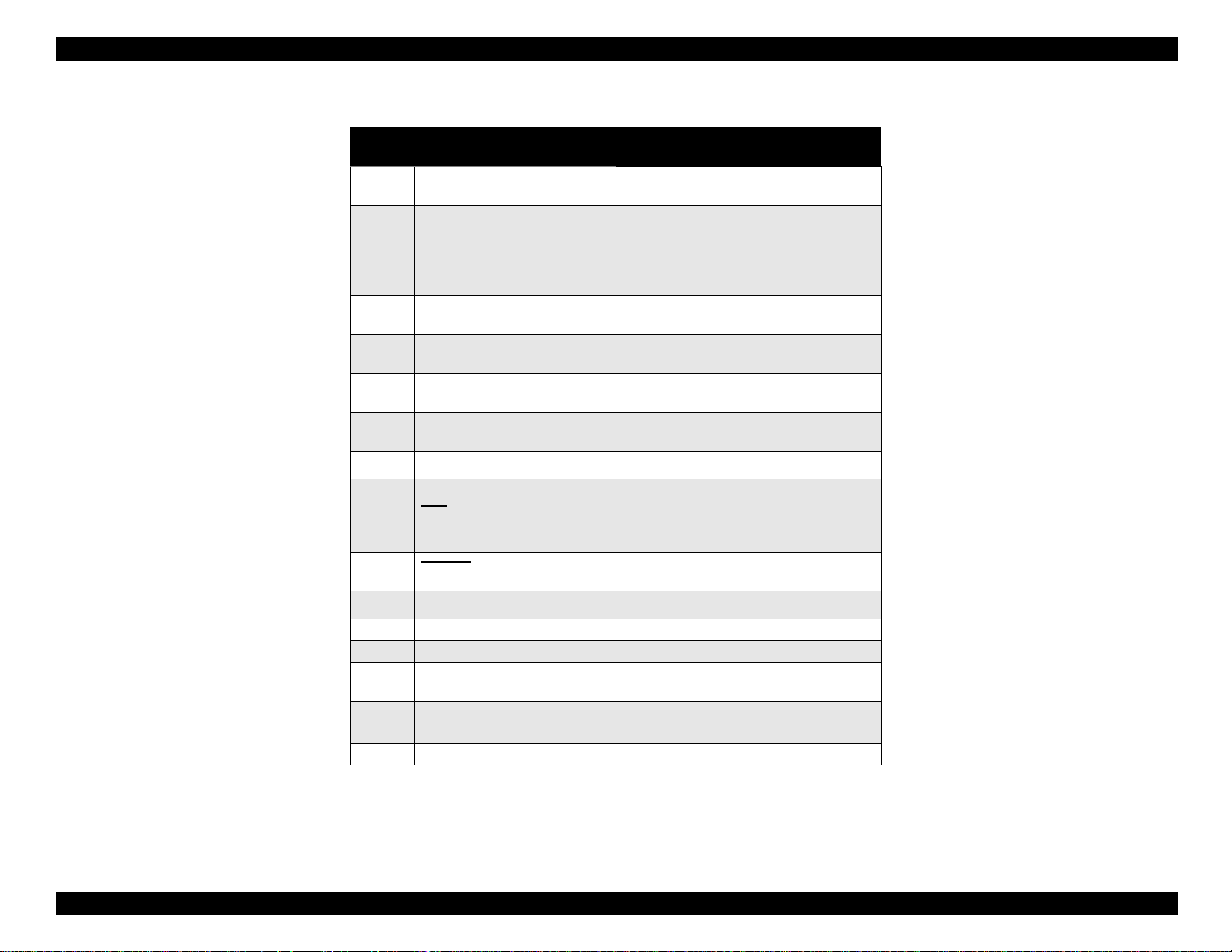
1.4.2 Control Panel Functions
Tables 1- 19 t hrough 1-21 desc ribe control panel fun c tio ns .
Table 1-20. Control Panel Functions
Button Function
Load/Eject
(Hold at least 2
seconds)
Load/Eject
(Press for less than
2 seconds.)
Cleaning
(Hold at least 2
seconds)
Cleaning
(Press for less than
2 seconds)
1. Starts the ink cartridge r eplacement sequence.
1. Loads or ejects the paper.
2. If the cartridge is in the ink change position, ret urns it to the
capping position.
1. Starts the printhead cleani ng sequence.
2. When the printe r is low on ink or out of ink (either cartridge),
starts the ink cartridge replacement sequence.
1. If the carriage is in the ink ca rt ridge ch ange posit ion, return s
it to the capping position.
Table 1-21. Control Panel Functions at Power On
Switch Function
Load/Eject 1. Starts status printing. 1
Cleaning
Load/Eject
+
Cleaning
Stylus COLOR 440 and 640:
Changes the code page. 2
Stylus COLOR 740:
Enters the default setting mode. 3
Enters the EEPROM Reset mode. (The Load/Eject LED
flashes for a few seconds.)
(Used only to clear a maintenance error.)
NOTES: 1. Prints the firmware version, ink counter value, and nozzle
check pattern.
during Normal Printer Use
Table 1-22. Control Panel Functions in the EEPROM Reset Mode
Button Function
Cleaning Resets the EEPROM.
1. After the Load/Eject LED has been flashing for about 2
seconds, press and hold down the Cleaning button for 10
seconds.
Stylus COLOR 440 and 640
After 10 seconds, both the Bl ack Ink Out and Color Ink Out
LEDs come ON simultaneously.
Stylus COLOR 740
After 10 seconds, the Load/Eject, Black Ink Out and Color
Ink Out LEDs all
2. Do one of the fo l lowi n g:
Stylus COLOR 440 and 640
After you confirm that both the Black Ink Out and Color Ink
Out LEDs are ON, release the Cleaning button. The print er
resets certain addresses in the EEPROM as it begins the
initia li zation process.
Stylus COLOR 740
After you confirm that all 3 LEDs are
Cleaning but ton. The prin ter resets certain addresses i n the
EEPROM as it begins the initializati on process.
flash
simultaneously.
flashing
, release the
NOTES: 1. Before you press the Load / Eject button, be sure you are
in EEPROM reset mo de (see Table 1-20)
2. The f ollowing ad dresses are res et in EEPROM Reset
Mode: timer IC (power-off timer), ink counter, and
interfa ce s election (int erf ac e selectio n is res et to Auto)
3. If you repeat the EEPROM reset operation, it reset s the
EEPROM addre sses but does not necessarily initialize
the EEPR OM. Whe th er or not the EEPROM is initialized
depen ds on the power-off time m onitored by the tim er IC.
2. Code pages for th e St y lus COLOR 440 and 640 are not
available.
3. The us er c an use the parameter lis t to se lec t s et t ings for
both the st andard and N LSP version of the Stylus
COLOR 74 0.
25
Page 35

EPSON Stylus COLOR 440, 640, and 740 Chapter 1 Product Description
1.4.3 LED Indicators and Printer States
Table 1-23 describes t he appearance of the LE D indicators during
various pr int er states. Y ou can use the ta ble below to determine t he
nature of a printer probl em and how to so lv e it .
Table 1-23. Printer Condition and LED Status
Printer State
Power on ————9
Ink sequence mode On — — — 6
Ink cartridge replacement mode Flashing — — — 5
Data processing Flashing — — — 8
Paper out Flashing — — On 4
Paper jam — — — Flashing 3
No ink cartri dge or i n k out (black) — On — — 7
Ink low (black) — Flashing — — 7
No ink cartridge or i nk out (color) — — On — 7
Ink low (color) — — Flashing — 7
Enter EEPROM reset — ON (for 3 seconds) —
Maintenance request Flashing Flashing Flashing Flashing 2
Fatal error Flashing On On Flashing 1
Power Ink Out (Black) Ink Out (Color) Paper Out
Indicator Sta tus
Priority
26
Page 36

EPSON Stylus COLOR 440, 640, and 740 Chapter 1 Product Description
g
y
g
(
g
g
g
ging
g
g
y
y
g
g
y
y
g
g
g
y
y
g
(
j
j
j
1.5 Error Conditions
When the error conditions described in the following sections occur, th e
printer stops acceptin
and the Bus
information on the st at us of th e LED indicat ors durin
states.
signal to HIGH , and stops pr int ing. See Sec ti on 1.4.3 fo r
1.5.1 Ink Out
When the printer is almo s t o ut of any color of ink, th e appropriat e Ink
Out indicator
When the printer is out of either ink co lor, it stops pri nt in
appropr iat e I nk Out indicat or remains on. In s ta ll a new ink car tr id
this time.
CAUTION
black or co lor) flashes and the printer k eeps on prin t ing.
Never reinstall an ink cartridge that has been removed
from the printer. Installing an old ink cartridge
interferes with the printer’s ink level detection
capability and may cause serious printing problems.
data, sets the interface ERROR signal to LOW
various err or
and the
e at
2. As lon
cannot ent er the printhead. Howe v er, if an old ink ca rt rid
removed from the printer, an
full
bubbles will form. If thickened ink
the ink pa t h or nozzle and cause ser ious printhead dama
3. Normally, the ink consumption counter is reset when the ink
cartrid
unnecessaril
value, a nd the printer m a
ink cartrid
as the ink ca rt ridge remains ins t alled in the pr int er, air
e is
air entering the cartridge can never be
absorbed into the ink. As a result, the ink w ill t hic k en and
ets into the pri nt head, it can clog
e.
e is removed. If an ink ca rt ridge is removed and reins t alled
, the ink co ns um ption counter will hav e t he wrong
keep printing even though the inksta lled
e is empty. This can damage the printh ead.
1.5.2 Paper Out
When the printer is printing and fails to lo ad a sheet of p aper after all
power-on operat ions
press the Load/E
indicat es a paper out er ror.
including timer clearing) are done, or after you
ect button and the pape r fa ils to load, the print er
1.5.3 Pa pe r Jam
Here’s why:
1. Once the ca rt rid
the printhead, and bubbles that form can prevent the printhead from
dischar
durin
ink itself, si nc e t he ink in the ca rt rid
the production process. However, the ink’s abilit
for onl
installation of a new ink c art ridge can be absorbed in t o th e
about one hour after th e c artridge has been ins t alled.
e has been removed, air enters the ca rt ridge and
ink properly. On the other hand, the air that ente rs
e has been de-aerated during
to absorb air lasts
When th e printer cannot eject a sheet of paper after printing, or when
the Load/ E
indicat es a paper
ect butto n on the contro l panel is press ed, the print er
am error.
27
Page 37

EPSON Stylus COLOR 440, 640, and 740 Chapter 1 Product Description
g
g
g
g
g
g
g
g
g
y
g
q
g
y
q
g
g
ge g
g
g
g
q
1.5.4 No Ink Cartridge
The following can be reas ons for the printer to indic at e a No Ink
Cartrid
1. The printe r is bein
e error:
turned on for the first time. This is a normal
conditio n, and the printer clears the error state as s oon as an ink
cartridge is installed.
2. Ink cartrid
occur if the carria
procedure, or if the carria
cartrid
ain correctly, the prin te r c lears the error c ondition.
a
3. There is a problem with the carria
If the error oc c urs when th e ink c artrid
correctl
indicate s a No In k Ca rt rid
e replacement is pe rf orm ed incorr ec t ly. This error m ay
e is moved during the cartridge repla c em ent
e returns to the home position before the
e is installed. When ink cartridge replacem ent is perfo rm ed
e sensor or with the printer itself.
e has been ins t alled
, or if the printe r so m et im es prints no rm ally and sometimes
e error, th e C R se ns or or printe r m ay
need to be repaired.
1.5.5 Maintenance Request
Since 1 c ounter poin t e
followin
EPSON Stylus COLOR 440 420 ml
EPSON Stylus COLOR 640 396 ml
EPSON Stylus COLOR 740 818 ml
:
Printer Maximum Ink Capacity
uals 0.02 m l of ink , ink ca pacity is set at the
CAUTION
When you print the A4 nozzle check pattern after
completing repairs, the print out shows you the cur rent
value of the total ink counter and whether the ink is
discharging properly from all the nozzles. Make sure
that the value of the total ink counter is acceptable. If
the value is too high (if it is close to or gre ate r than t he
maximum value), it may be necessary to clear the
EEPROM and replace the waste ink pad.
1.5.6 Fatal Errors
The follo w ing are fatal er rors :
When t he t ot al quantity of ink released by cleaning and flushing reaches
the threshold value, a maintenance re
stops print in
. You need t o replace the waste ink pad in the prin t er
uest error occurs and the printer
case. A print er counter m onitors the am ount of ink that has been
absorbed by the waste in k pad. The coun t er uses a point system that
corresponds to the amount of ink that has been used. The maximum
capacit
points
EPSON Stylus COLOR 440 21000
EPSON Stylus COLOR 640 19800
EPSON Stylus COLOR 740 40900
of the waste ink pad is set at the following
:
Printer Maximum Counter Points
maximum counter
Carria
carria
belt tension malfunction, not enou
e Contro l Error: This e rror may be cause d by a misaligned
uide shaft, a home position sensor malfunction, a timing
h lubricant on the carriage guide
shaft, or ot her problem s .
CG Access Error: This error occurs if the carria
the ink cart rid
se
uence.
e replacem ent positio n during the replac em ent
e does not move to
28
Page 38

EPSON Stylus COLOR 440, 640, and 740 Chapter 1 Product Description
y
(
g
(a)
(b)
(c)
(d)
y
g
g
(a)
(b) Ej
(c)
(d)
(e)
g
(a)
(b)
g
g
g
g
g
g
g
g
)
1.6 Pr in te r In itialization
Stylus COLOR 440, 640, and 740 have three kinds of initialization
methods, as described below:
Power-on initialization
Power-on initialization occurs when
printer rec eiv es the cold res et c om mand
Power-on initializat ion performs t he followin
Initializes the printer mechanism.
Clears the input data buf f er.
Clears the print buffe r.
Sets the default values.
Operator initialization
Operator initializat ion occurs when
seconds af t er it was turned off, or when the printer receives th e I N IT
nal (negative pulse) from the parallel interface. Operator initialization
si
performs t he followin
acti ons:
ou turn the pri nt er on, or when the
remote RS command).
actions:
ou turn the printer on less t han 10
1.7 Initialization Settings
The settings below take effect when the Stylus COL OR 440, 640, or
740 are init ialized. If the us er chan
panel bu t to ns , th e D ef ault Settin
settin
s will take effect instead of the facto ry settings.
e position: Page headi ng location fo r c urrent page
Pa
Line spac in
ht margin positio n: 80 lines
Ri
Left mar
Charac t er pitch: 10 cpi
Printin
: 1/6 inch
in position: First line
mode: Text mode (not raster graphics mode
es any settings using the control
mode, or remote commands, those
Caps the printhead.
ects the p aper.
Clears the input data buffer.
Clears the print buffer .
Sets the default values.
Software initialization
Software initializat ion occurs when the prin t er receives the ESC @
command. Software initializat ion performs the followin
Clears the print buffer .
Sets the default values.
actions:
29
Page 39

EPSON Stylus COLOR 440, 640, and 740 Chapter 1 Product Description
(
g
)
g
)
y
y
)
y
y
y
)
y
y
y
(PF)
y
g
g
1.8 Main Components
The main components of the Stylus COLOR 440, 640, and 740 are
listed below.
the lower h ousin
1) Upper housin
2) Printer m ec hanism
3
4
5
Note that t he bottom of th e printer mec hanism se rv es as
for all three pr int ers.
Main con t rol board
lus COLO R 440: C206 MAIN-B board,
St
C255 MAIN board *
Stylus COLO R 640: C256 MAIN board
lus COLO R 740: C257 MAIN board
St
Power s upply board
lus COLO R 440: C206 PSB /P SE board
St
lus COLO R 640: C206 PSB /P SE board
St
St
lus COLO R 740: C257 PSB /P SE board
Contro l panel board
lus COLO R 440: C206 PNL board
St
St
lus COLO R 640: C206 PNL board
lus COLO R 740: C209 PNL board
St
1.8.1 Printer Mechanism
Like the printer mech anism for ea rlier printers s uc h as the Stylus
COLOR 600, the paper feed
mechanism and the ink pump. However, the ink pump operates onl
when the carria
approp riate direct ion.
Another important f eature is tha t the printhea d is one unit, combinin
both blac k and color ink nozzles.
e is in its home position and the PF motor is turning the
motor drives both the paper feed
* The C255 MAIN board will eventually replace the C206 MAIN-B.
30
Page 40

EPSON Stylus COLOR 440, 640, and 740 Chapter 1 Product Description
g
y
g
g
1.8.2 C206 MAIN-B Board (Stylus COLOR 440)
The C206 M AI N -B board co nt rols the operation of the printer
mechanism and data processin
This boar d w ill ev entuall
be replaced by the C255 MAIN board.
The C206 MAIN-B board consists of the following major components:
IC 14(PF)IC 15(C R )
CN6CN7
CN10
IC 7(H ead)
CN8
EEPRO M
(IC 1 1 )
Q 7,Q 9(H ead)
operations for the Stylus COLOR 440.
IC 3 (P -R O M )
CN1
IC 1 (C P U )
IC 2 (A s ic )
B a tt 1
IC 4 (4 M D -R A M )
CN3
CN5
CN4
CN11
1.8.3 C256 MAIN Board (Stylus COLOR 640)
The C25 6 M AIN board c ontrols the operation of t he printer mec hanism
and data processin
of the followin
IC 15(C R )
CN10
IC 7(H ead)
operations fo r t he Stylus COLOR 640. It consists
major components.
IC 14(PF)
CN6CN7
CN8
Q 7,Q 9(H ead)
CN1
IC 1 (C P U )
IC 2 (A s ic )
IC 16(P-R O M )
CN2
B a tt 1
IC 6
IC 5 (4 M D -R A M )
Figure 1-13. C256 MAIN board
CN3
CN5
CN4
CN11
Figure 1-12. C206 MAIN-B board
31
Page 41

EPSON Stylus COLOR 440, 640, and 740 Chapter 1 Product Description
g
g
y
g
(
job)
gging
)
1.8.4 C257 MAIN Board (Stylus COLOR 740)
The C257 M AI N board controls the operation of the printer mec hanism
and data processin
of the follow in
HT1
IC 1 2 IC 1 3
(P F D riv e )
operations for the Stylus COLOR 640. It consists
major compon ents.
IC 14(H ead)
CN9
CN7
IC 1 5
(R e g u la to r)
CN8
IC11(CR)
IC 6 (C G :o n ly fo r N L S P )
IC 3 (P -R O M )
CN3
CN1
B a tt 1
IC 4 IC 5
(4M DRAMx2)
IC 1 (C P U )
IC 2 (A s ic )
IC 7(EEPRO M
CN2
CN3
CN5
CN4
CN11
Figure 1-14. C257 MAIN Board
1.8.5 Powe r Sup pl y Board C206 PSB/PSE (Stylus COLOR 440 and 640) C257 PSB/PSE (Stylus COLOR 740)
The pow er supply boards for the Stylus COLOR 440, 640 and 740
emplo
volta
can be su pplied to the printer for at least 30 seconds after po w er is
turned off. Therefore, even when the user makes a mistake
examp le, tu rns off power in the middle of a print
ensures that the printhead is capped and prevents ink from clo
nozzl e plate.
a switching regulator me th od to supply stabl e logic and power
es. Because thes e boards cont ain a time delay circuit, electrici ty
for
, this mechanism
Q1(FET)
CN1
Fuse(F1)
Trans(T1)
PC1
C51
CN2
the
Filter(L1)
C11
IC51
Figure 1-15. C206/C257 PSB/PSE board
32
Page 42

EPSON Stylus COLOR 440, 640, and 740 Chapter 1 Product Description
1.8.6 C206 PNL Board (Stylus COLOR 440 and 640)
The C206 PNL (panel) board is loc at ed in t he pa nel ho usi ng on the front
of the printer. It consists of 3 buttons, 4 LEDs, and 1 connector.
LED0
LED1
LED2
SW2
SW0
Figure 1-16. C206 PNL board
LED4
SW1
1.8.7 C209 PNL Board (Stylus COLOR 740)
The C209 PNL (panel) board is located in the panel housing on the fr on t
of the prin t er. It c onsists of 3 b ut to ns , 4 LE Ds, and 1 connector.
LED0
LED4
LED1
LED2
SW2
SW0
SW1
CN1
Figure 1-17. C209 PNL Board
33
Page 43

OPERATING PRINCIPLES
Page 44

EPSON Stylus COLOR 440, 640, and 740 Chapter 2 Operating Principles
g
(PH)
(
g
y
g
g
g
2.1 Printer Mechanism
The printe r m ec hanism inc ludes all the m echanical components that
enable pri nt in
to take place. These components include the printhead
and carriage (CR) unit, the paper feed (PF) and paper eject rollers,
the auto-sheet feeder
printhead cleanin
ASF), and the p um p unit which is us ed in
operations .
A uto-S heet
Feeder (AS F)
Paper Load
Trigger
Tim ing Belt
Paper Feed
Motor
Like some previous versions of EPSON ink jet printers, t he paper fee d
motor in the St
feedin
, but also t o pump ink and drive the auto-sheet fe eder. The
direction of the paper feed motor, alon
determines which operations are performed. Fi
lus CO LOR 440, 64 0, and 74 0 is us ed no t o nly for paper
with the positi on of the car riage,
ure 2-1 shows how the
main components of the printer mechanism interact.
Carriage Unit
(P rinthead)
C apping
M echanism
C a rria g e M o to r
PF Roller
Pum p
Figure 2-1. Printer Mechanism Block Diagram
35
Page 45

EPSON Stylus COLOR 440, 640, and 740 Chapter 2 Operating Principles
(Cy
g
y
(
)
)
y
(
)
)
y
(
)
)
y
g
g
j
g
g
g
g
g
gging
g
y
(
y
g
2.1.1 Printhead
The printh ead of the Stylus COL OR 440, 640, and 740 combines the
black and CMY
below, the nozzle co nf i
lus COLO R 440:
St
Black Nozzle: 64 nozzles
CMY Nozzle: 21 nozzles per color (90 dpi x 1 row
St
lus COLO R 640:
Black Nozzle: 64 nozzles
CMY Nozzle: 32 nozzles per color (90 dpi x 1 row
St
lus COLO R 740:
Black Noz z le: 144 no z z les
CMY Nozzle: 48 nozzles per color (120 dpi x 1 row
The Stylus COLOR 640 and 740 print at the highest resolution (720 x
1440 dpi
, while the Stylus Color 44 0 prints at 720 x 720 dpi.
The printh ead uses an on-dema nd MACH-t
Refer to Fi
confi
ure 1-1, Figure 1-2, and Figure 1-3 for the nozzle
uration. In or der to correc t manufactu ring variation s in th e piezo
element s u s ed f or e
head volta
e ID to the printer whenever you replace the printhead, main
board, or printer mechanism. The head volta
side of the printhead , an d is s to red in the EE PR OM on the printer’s
main board. You can input the ID to the printer by using the adjustment
ram des c ribed in “Using the Adjustment Program” in Chapter 5,
pro
Adjustments
.
an, Magenta, Y ellow) heads in one unit. As shown
urations are different f or each model:
90 dpi x 2 row s st aggered
90 dpi x 2 row s st aggered
120 dpi x 3 row s s t aggered
pe ink deliv ery system.
ecting ink from the nozzles, you must input the
e ID is marked on the
Printing Process
In Figure 2-2, the ink c art ridge sensor de te c ts t he presence of the ink
cartrid
ink flows out of t he c artrid
filter. The filter prevents dust or dirt from clo
causin
until it is read
elements
board, the PZTs compress the top of the ink cavit
throu
e; note that the sensor’s position differs between models. After
e through the needle, it passes th rough a
the ink nozz les and
missing dots or ink deflection. The ink cavity then stores the in k
to be discharged. This is accomplished by piezo electric
PZTs). In response to signals from t he driver on the m ain
, causing ink to eject
h the nozzle plate on the bottom of the printhead.
N o z z le S e le c to r B o a r d
Ink Cartridge S ensor
(S tylus C O LO R 440,640)
Ink Cartridge Sensor
(S tylus C O LO R 740)
N eedle
(In k C a rtrid g e )
PZT
F ilte r
ozzle P late
In k C a v ity
Figure 2-2. Printhead Sectional Drawing
36
Page 46

EPSON Stylus COLOR 440, 640, and 740 Chapter 2 Operating Principles
g
g
y
)
g
g
y
(
y
g
g
g
j
g
)
The following figures show s ec t ional drawi ngs of the printhead while
waitin
to print an d during printing (normal state and ejecting state).
Normal State:
Durin
the ducts between the ink cavit
the normal state, the PZT elements do no t mov e and ink fills
and the nozzles. (Refer to Figure
Ink Course
PZT
Cavity
2-3.
Ejecting State:
The printh ead is desi
throu
c
h thousan ds of print cycles each second. During each print
cle, the main board transmits data to the nozzle selector IC
ned to operate at a high frequency, and goes
Nozzle
Nozzle Plate
IR2C72C), which is located on the printhead. This data determines
which PZTs are to be actuated in the current c
time, the main board
Durin
volta
causes ink to e
Fi
each print cycle, the noz z le s elector applies this dr iv e
e to specific PZTs, as determined by the print data. This
ect from th e nozzles in a specific patt ern. (See
ure 2-4.
enerates a high-frequency drive voltage.
cle. At the same
Figure 2-3. Printhead - Normal State
Figure 2-4. Printhead - Ejecting State
37
Page 47

EPSON Stylus COLOR 440, 640, and 740 Chapter 2 Operating Principles
g
g
g
g
y
Rotor
1
2
3
4
A
/A
B
/B
Coils
2.1.2 Carriage Mechanism
The carriage (CR) motor moves the carriage, which holds the printhead,
alon
the carriage guide shaft. Unlike the paper feed motor, the
carria
advance th e c arria
motor is a 4-phase, 200-pole stepper motor. Its specifications are
shown in the table bel ow .
The carria
2-2, and W1-2 phase drive methods. The St
1-2, W1-2 , 2 W 1-2, and 4W1-2 phase driv e methods . Diff erent phase
drive methods are used for differ ent printer fu nc t ions, as show n below.
e motor is ca pable of Micr o-Step cont rol. (This means it can
e in increm ents of 1/360 of an inch.) The carriage
Table 2-1. Carriage Motor Specifications
Items Description
Motor type 4-phase/200-pole stepper motor
Drive voltage 42 VDC ± 5%
Internal coil resistance 7.8 ohms ± 10% (per phase under 25 °C
environment)
Driving speed (frequency) 5 cps (60 Hz) to 340 cps (4080 Hz)
Control method Bi-polar drive
e motor for the Stylus COLOR 440 and 640 is driven by 1-2,
lus CO LOR 740 us es 2- 2,
Table 2-3. Phase Drive Methods (Stylus COLOR 740)
Printing mode
High-speed skip 340 4080
Normal printing 200 2400 W1-2, 2-2 phase drive
Capping 80 960 2W1-2, 2-2 phase drive
Wiping 40 480 2W1-2, 2-2 phase drive
Opening the bleed
valve
Uncapping 5 60 4W1-2, 2-2 phase drive
Drive Speed
[CPS]
20 240 4W1-2, 2-2 phase drive
Drive frequency
[PPS]
Drive method
W1-2, 2-2,1-2
phase drive*
Table 2-2. Phase Drive Methods (Stylus COLOR 440, 640)
Printer function
High-speed skip 340 4080
Normal printing 200 2400 W1-2, 2-2 phase drive
Capping 80 960 W1-2, 2-2 phase drive
Wiping 40 480 W1-2, 2-2 phase drive
Opening the bleed
valve
Uncapping 5 60 W1-2, 2-2 phase drive
Driv e S peed
[CPS]
20 240 W1-2, 2-2 phase drive
Drive frequency
[PPS]
Drive method
W1-2, 2-2,1-2
phase drive
Figure 2-5. CR Motor Circuit Diagram
38
Page 48

EPSON Stylus COLOR 440, 640, and 740 Chapter 2 Operating Principles
(
y
g
g
g
ge g
g
g
2.1.3 Platen Gap and Parallelism Adjustment Mechanisms
The platen gap (PG) adjustment lev er changes the distance between
the printh ead and the p lat en.
between 1.04 mm and 1.74 mm. Normall
forward p os it ion, or narro w
printin
to increase the
All media Front 0 mm
If you experience
print problems
, such as paper curl, the user can move the lever toward the rear
ap.
Table 2-4.
Paper Lever Position PG adjustment value
Platen Gap Adjustment Lever Settings
Rear 0.7 mm
See Figure 2-6.) The distance can vary
, the lever is k ept in the
ap setting. In case of problems during
(1.04 mm between head and platen)
(1.74 mm between head and platen)
The parallelism adjustment levers, mounted on the left and right ends of
the carria
uide shaft, adjust alignment be tween the pla t en and the
uide shaf t . Pa rallelism m us t be c hecked and adjusted whenever a
new
uide shaf t is installed on t he printer mechanism, whether during
the produc t ion process or repair. For det ails, see “
Adjustment” in Chapte r 5,
Adjustments
.
Parallelism
Paper Feed Motor
Eject Roller
Paper guide(Front)
Carriage Home Position Sensor
PF Roller
Timing Belt
PG Lever
Carriage Unit
Front
Bushing
Figure 2-6. Carriage Mechanism (Top View)
Carriage Motor
Rear
Parallelism
Adjust Lever
Carriage
Guide Shaft
39
Page 49

EPSON Stylus COLOR 440, 640, and 740 Chapter 2 Operating Principles
g
g by
g
g
g
g
g
j
g
g
j
g
g
y
g
y
y
g
2.1.4 Carriage Lock Mechanism
The carriage lock mec hanism prev ents the pr int head from becoming
uncapped, which could happen beca us e of vib rat ion durin
mishandlin
users. If the printhead is uncapped fo r a long time, ink
on the print head surfac e dries out and becomes t hick. This can keep
the nozzle from discharging ink. To prevent this, the printer locks the
carria
e under the f ollowing conditio ns :
After power-off:
If the powe r is tu rned off durin
printing or any other operation, the
printer initializes and then locks the carria
After power-on:
The printer locks the carria
automatic power-on cl eanin
e after the power is tur ned on and
is completed.
After ejecting the paper:
If the Load/E
data is bein
locks the carria
Load/E
not perfor m a c arria
ect button is pressed during printing and no furth er
receive d by the printe r, th e printer ejects the paper,
e, and goes into standby. However, if the
ect button is pressed for paper loading only, the printer does
e lock.
e in the hom e position.
trans port or
2.1.5 Pa pe r Fe ed Mot or
The paper feed (PF) motor powers not only the paper feed mechanism,
but also th e pump mech anism that is us ed for printhead clean in
pe of motor used is a 4-phase hybrid pulse m ot or. This mak es it
t
possible to use the same motor to perform both hi
operations for a var iet
of paper fe eding and ink pumping tasks.
h- and low-speed
The PF motor for the Stylus COLO R 440 and 640 us es 2-2 and 1-2
phase drive methods, whereas the St
W1-2, 1-2 and 2-2 phase drive methods. The followin
lus COLO R 740 uses 2W 1-2,
tables show the
PF motor specificat ions.
Table 2-5.
Item Description
Motor type 4-phase/48-pole steppe r motor
Drive voltage 42 VDC ± 5%
Coil resistance 7 ohms ± 10% (each coil, at 25 °C)
Drive frequency 100 to 1990 Hz
Control method Bi-polar drive
Table 2-6.
Item Description
Motor type 4-phase/200-p ole stepper motor
Drive voltage 42 VDC ± 5%
Coil resistance 8.8 ohms ± 10% (each coil, at 25 °C)
Drive frequency 100 to 3240 Hz
Control method Bi-polar drive
PF Motor Specifications (Stylus Color 440, 640)
PF Motor Specifications (Stylus Color 740)
. The
40
Page 50

EPSON Stylus COLOR 440, 640, and 740 Chapter 2 Operating Principles
y
g
g
g
y
y
g
g
g
g
y
g
g
g
g
2.1.6 Paper Handling
Paper ha ndling on the Stylus COLOR 440, 640, and 740 is per fo rm ed
b
the automatic sheet feeder (ASF) and paper feed mechanisms. The
ASF is desi
fed into the printer at a time. After the ASF has int roduced a sin
ned to prevent more than one sheet of paper from being
le
sheet into the printer, the paper feed mechanism takes over. It
manages the pape r during printing, and also ejects the page when
printin
is complete.
Since the paper feed mechanism and ASF share the same motor, the
printer needs a wa
This is done b
of transmitting power to th e ASF during loading.
the ASF transmission.
ASF transmission
Normally, when the the PF motor is running, it turns only the gears on
the ri
These
When the Load/Eject switch is p res s ed or the prin te r receives
instructions to load a new sheet of paper, the carria
wa
then push es a
axle as the platen rolle r drive
mesh with the ASF roller transmission
drives the ASF durin
ht-hand s ide of the ASF tr ansmission, as shown in Figure 2-7.
ears incl ude the PF roller drive gear and the eject roller driv e
ear, which are both part s of th e paper feed m ec hanism.
e unit moves all the
to the left an d presses against the sheet feeder clutch. The clutch
ainst the sl iding gear, which is mounted on the same
ear. This c aus es the slidi ng gear to
ears. In this way, the PF motor
paper load ing.
ASF Roller Drive Gear
Sliding Gear
(Hidden)
ASF Roller Transmission Gears
PF Roller Shaft
Figure 2-7. ASF Transmission
Sheet Feeder
Clutch
Eject Roller Drive Gear
Eject Roller
Transmission Gear
PF Motor Pinion Gear
PF Roller Transmission Gear
PF Roller Drive Gear
41
Page 51

EPSON Stylus COLOR 440, 640, and 740 Chapter 2 Operating Principles
g
g
y
g
y
g
y
y
Automatic Sheet Feeder (ASF)
When the us er s ets a stack of paper in the pr int er, it rests on to p of th e
upper led
e of the
pad
, shown in Figure 2-8. The st ac k rem ains on the
pad while individual sh eets are fed in t o th e paper path . Som etimes,
howeve r, more than one sh eet of paper slips into the paper path dur ing
printin
. If this is not corrected, it can cause paper to jam when the
printer trie s to load the next sheet of paper. To preve nt th is , the PF
motor rotates backwards at the beginning of each pa per feed cycle.
This causes the cam to rotate counterclockwise, catch the paper return
lever, and lif t it upward, as sh ow n in the figure at right. At the same
time, the hopper and the pad are pushed backwards, awa
cut paper loadin
As the cam continues to rotate, an
paper path is cau
roller, leaving a gap to prev ent frict ion wi t h the paper.
paper that has slipped into the
ht by the return le v er and return ed t o it s proper
from the D-
position on top of the pad.
When the PF motor resumes normal forward motion, the cam and the
D-cut roller rotate clo ckw ise, allow ing the paper ret urn lever to m ov e
downwa rd and clear the paper pat h. At th e s am e time, the hopper and
the pad mo v e f orw ard and pres s t he paper against the D -c ut roller. As
the D-cut ro ller continues to turn, it d raw s t he top sheet of paper off the
stack and feeds it into the printer, until the roller has turned so that its
flat side is pa rallel to the paper. At this point, the pa per is full
and onl
the paper pinch roller rem ains in cont ac t wi th th e paper. This
loaded
is the ASF’s home position. A sensor detects this position and causes
the printe r to dis engage power from the ASF.
D-Cut Roller Cam
Paper R eturn
Lever
H opper
H opper Spring
Pad S pring
Pinch R oller
Paper Stack
Pad
Figure 2-8. ASF Unit Operation
42
Page 52

EPSON Stylus COLOR 440, 640, and 740 Chapter 2 Operating Principles
j
g
g (
g
g
g
g
g
g
g
gag
y
y
(
)
Paper Feed Mechanism
When the ASF loads pap er into the print er, the PF an d pinch roller s
receive it. Th es e rollers in turn move the paper across th e platen,
where printing takes place, and feed it out through the eject rollers. The
ect roller is not c hed and set bac k fro m the low er eject roller at a 5-
top e
ree angle toward the platen. This compensates for paper curl and
de
allows the t railin
without bendin
Paper
top) edge of the pap er t o pass under t he printhea d
.
Notched
Eject Roller
Eject Roller
Printhead
5 degrees
Pinch R oller
PF Roller
Platen
2.1.7 Ink System
The ink system consists of the following:
ink cartrid
printhead cappin
carria
cleanin
ink pump
waste ink drain pad
Althou
h the PF mot or drives bot h th e paper feed m ec hanism and the
ink pum p, th e
disen
alwa
e these systems. However, this does not mean the pump is
s pumping ink. For the ink pump to operate, the p rint head must
be capped b
the PF motor must turn the pump in the appropriate direction
the pum p drive roller s
Eject R oller
Transm issionG ear
e
mechanism
e lock
blade
ear linkage contains no special mechanism to
the capping mechanism (to create a vacuum seal) and
.
PF R oller D rive G ear
Eject R oller
D rive G ear
C arriage Lock
to engage
Figure 2-9. Paper Feed Mechanism
C leaning Blade
P F M o to r
Pinion G ear
Pum p
C apping U nit
Figure 2-10. Ink System Mechanism
43
Page 53

EPSON Stylus COLOR 440, 640, and 740 Chapter 2 Operating Principles
ying
g
j
g
g
g
g
ging
g
ging
g
y
g
g
g
g
g
g
g
g
g
Head Cleaning Operations
Suctioning
The printe r performs a va riety of tasks to keep the printhead clean and
to keep ink f rom dr
out on the printhead’s surface. These tasks
include:
Rubbing and Wiping
Rubbin
and dirt on t he printhea d. Th is helps mainta in normal ink e
and wiping are perform ed prior to suc t ioning to elimina te dus t
ection and
ensures tha t a fir m se al can be obtained whe n t he printhea d is ca pped
during suctioning.
Rubbing and wiping occur when the printhead passes over the cleaning
blade, wh ic h c an be extended into the path of the p rint head or
withdrawn out of its way. To learn how this works, see “Pump
Mechanism” on page45.
The cl eaning blade is composed of t w o m at erials: felt on the left side
and rubbe r on the ri
rubs
printhead
against the rubber half of the blade. When the carriage
moves left to ri
amount of ink is sent to the nozzle surface before wipin
adherin
objects come off easily.
ht. When th e c arriage moves right to left, the
ht, the print head
wipes
against the f elt half. A small
to make
Suctionin
ink awa
prevent s ink f rom remainin
takes plac e w hen the prin t er us es the ink pu m p to suction
from the nozzles. Th is elim inates tra pped air bubbles and
near the nozzles and drying out.
The print er performs s uc t ioning at three diff erent power levels. During
hi
h-power suctioning, the printhead is fully capped and the bleed valve
remains c los ed. This
switches to medium-power suctionin
ives rise to m ax im um suction. The printe r t hen
, a sensitive operatio n performed
with the bleed valve open. This elim inates air bubbles form ed in the
printhead cavity during high-power s uc t ioning. Finally, with the bleed
valve still open but the pump motor runnin
perform s low -power suc t ionin
. This vacuums away any ink that
remains on the nozz le plate and in the ink c ap followin
at a lower speed, the printer
other cleaning
procedures.
The fi
various head clean in
ure belo w sh ow s w here the carriage is positioned during the
operations .
Printable Area
Discharging
Dischar
printhead. Unlike suctionin
is the elect ronically controlle d ejection o f in k fro m th e
, which uses an external pump, discharging
uses the printhead’ s o w n PZTs to perform the operation. Dischar
eliminate s th e v is c ous ink that fo rm s w hen ink near th e printhead
nozzles starts drying out.
FG
A: Medium- and low-power suctioning position
B: High-power suctioning position (home position)
C: Discharging position (right)
D: Wiping/rubbing position
E: Cartridge replacement position
F: Discharging position (left)
G: ASF drive position
ABCDE
Figure 2-11. Carriage Positioning
44
Page 54

EPSON Stylus COLOR 440, 640, and 740 Chapter 2 Operating Principles
g
g
g
g
g
g
y
g
y
y sq
g
g
g
g
Pump Mechani sm
The pump mechanism, shown in Figure 2-12, ac t ually perform s three
different functions:
The pump itself removes ink from the ink cartrid
head cleanin
The cl eanin
part of the head clean in
The carria
operation.
blade removes dust and dirt from th e printhead , a s
operation.
e lock retains the carriage in its home position, to ensure
e, as part of the
that the printhead remains capped when the printer is not in us e.
The cl eanin
blade and th e c arriage lock are mounted on the same
slider unit , a nd t herefore e xtend or retra c t in ta ndem. The slider’s
motion is c ont rolled by the slider lev er, which is held against the clutch
plate b
friction ins t ead of
to turn even when the slider unit is full
a compre ssion spring. Because th e s lider lever is operated by
ears, the rest of the pum p mechanis m c an continue
extended or ret racted.
However, this also means that even a minor obstruction can cause the
slider to sti ck.
The pump itself uses pe ris t alt ic c om pression. R ollers attached to the
pump driv e w heel create a vacuum in th e ink drain tube b
the tube al on
shown in Fi
followin
its length and forcing the ink to tra v el t hrough it. This is
ure 2-12 at right, an d s c hematically in Figure 2-13 on th e
page.
ueezing
Eject R oller
Shaft
Gear B
Gear C
C lutch plate
Com pression
spring
Gear A
Pum p drive
w heel
Slider lever
Rollers
C leaning blade
C a rria g e lo ck
Slider
Figure 2-12. Pump Mechanism
In k d ra in
tube
C apping unit
As mentioned abov e, th e PF m otor is the po w er source fo r both the
paper feed mechanism and the pump mechanism. The PF motor
powers the pump mechanism through the eject roller shaft, as shown in
Fi
ure 2-10 and Figure 2-12 at right.
45
Page 55

EPSON Stylus COLOR 440, 640, and 740 Chapter 2 Operating Principles
g
g
g
y
y
g
y
g
(
g
y
g
(
g
g
g
g
Although economy of design results from th e pump mec hanism a nd th e
paper feed mechanis m s harin
the pump to be runnin
every time the printer feeds paper. To
overcome this problem, the ope rations of pa per feedin
are kept separate b
the PF mot or’s directio n of rot ation. Sinc e t he
printer fee ds paper in one direction onl
for runnin
the pump.
the same motor, it is not desirable for
and pumping
, the other direction is re s erv ed
Here’s how that works: Slots in the pump’s drive wheel permit two
rollers to move radial l
direction of rotation. As shown in Fi
counterclockwise
are forced out w ard to com press a
caus ed b
the angle of the slots and friction between the rollers and the
drain tube. In this position, pumpin
turns clockwise
move inward, and no pum pin
CCW Rotation
inward or out w ard, depen ding on the wh eel’s
ure 2-13 , when the pump turns
as viewed from the left side of the printer), the rollers
ainst the ink drain tube . This is
takes plac e. W hen the pump
the direc ti on of paper feeding), the rolle rs relax and
occurs.
C W R o ta tio n
The tab le below sum m arizes the re lat ionship be tween the PF m otor’s
directio n of rotation and the pump m echanism ’s operation .
Table 2-7.
PF Motor Rotation Pump Mechanism Functions
Clockwise (CW) Pump operates
Counte rc lo c kwise (CCW) Pump does not operate
PF Motor and Pump Mechanism Functi ons
Head cleaner extends
Carriage lock extends
Head cleaner retracts
Carriage lock retracts
For the p um p to drain ink aw ay from the cartridge, not only must the
pump be runnin
printhead cappin
followin
section ex plains the operation of th e c apping mechanism.
, but the print head must be f irm ly seated on the
mechanism with the air bleed valve closed. The
Tube com pressed
Tube released
Figure 2-13. Pump Rotation
46
Page 56

EPSON Stylus COLOR 440, 640, and 740 Chapter 2 Operating Principles
g
g
g
g
g
g
g
Capping Mechanism
The capping mechanism s eals the print head whe n t he printer is not in
use. This pr ev ents the ink f rom t hic k enin
to the air. Also, the cappin
mechanism creates a vacuum seal around
the printh ead, which e nables ink su c ti onin
due to con ti nuous expos ure
to take place.
Included in t he c apping mechanism is an air bleed v alue. See Figure
2-14. Durin
This enable s the pum p to
and low-power suctionin
pushin
high-power s uctioning, the blee d v alue is kept clos ed.
enerate maximum suction. During medium-
, the carriage moves all t he way to th e r ight,
the valve release pin against the f rame of the capping
mechanism. This opens th e bleed va lve and reduc es vacuum pressur e
in the cap.
Air bleed
hole
Valve-Closed
Position
Printhead guides
Ink drain
hole
Bleed valve
Valve closed
Valve-Open
Position
Cap
Valve open
Valve release pin
Figure 2-14. Capping Mechanism - Bleed Valve Operation
47
Page 57

EPSON Stylus COLOR 440, 640, and 740 Chapter 2 Operating Principles
y
y
y
y
g
2.2 Electronic Circuit Boards
The Stylus COLOR 440, 640, and 740 contain three circuit boards each:
lus COLO R 440:
St
Main: C206 Mai n-B or C255 Main Board *
Power Supply: C206 PSB, PSE Board
Control P anel: C206 PNL Board
St
lus COLO R 640:
Main: C256 Mai n Board
Power Supply: C206 PSB, PSE Board
Control P anel: C206 PNL Board
lus COLO R 740:
St
Main: C257 Mai n Board
Power Supply: C257 PSB, PSE Board
Control P anel: C209 PNL Board
The printer’s main electrical s
2-15 at ri
ht.
stems are connected as shown in Figure
* The C255 M ain board w ill ev entually replace th e C 206 Main-B board.
C206 PSB/PSE Board
C257 PSB/PSE Board
CR Motor
PF Motor
AC Input
+5 V D C
+42 V D C
C206 Main-B
C255 Main
C256 Main
C257 Main
+42 V D C
+5 V D C
HP S ensor
PE Sensor
Black/C olor Ink Cartridge Sensor
Ink-End C ounter
C206 PNL
C209 PNL
ASF Lever
Position Sensor
12
11
1
10
2
9
3
8
4
5
7
6
and Pow er-O ff
Tim er
+5 V D C
LE D
Therm istor
Printhead
N ozzle S elector
Figure 2-15. Connections Between Main Electrical Systems
48
Page 58

EPSON Stylus COLOR 440, 640, and 740 Chapter 2 Operating Principles
g
g
g
y
y
g
y
(
y
y g
g
g
)
y
y
g
g
y
gg
y
g
y
ging
g
(hig
y
(
(
g.)
y
y
y
g
2.2.1 Power Supply Board
The Stylus COLOR 440, 640, and 740 use one of two power supply
boards: the PSB, which accepts 120 volts, or the PSE, which accepts
240 volts. The difference between them lies in their primary circuitry,
which includes the pow er line filter, th e m ain switchin
the transformer. In the PSE, these components are desi
withstand hi
differences, the two boards are exactl
The power suppl
es power th e v arious printer function s sh ow n in the table below.
volta
her input v olt ages than in the PSB. Except for these
the same.
provides filtered output at 5 and 42 VDC. These
Table 2-8. Power Output Applications
Voltage Application
42 VDC CR motor
PF motor
Printhead PZTs
5 VDC Logic circuitry
Control signals
Sensors
Control panel LEDs
Printhead nozzl e selector IC
Built into the power suppl
is a delay circuit, which keeps the printer fully
powered for about 30 seconds after the printer is turned off.
onl
when you turn the power off by pressing the Power switch on the
not
front cont rol panel; the printer will
dela
path and to return the carria
ives the printer time to eject any paper that may be in the paper
e to its home position. (The carriage must
stay on if you unplug it.) The
return to its home position in order to cap the printhead. If the printhead
remains unc apped, ink dries out and clo
s the prin th ead.
transist or, and
ned to
This works
Power Supply Operation
When th e printer is plugged in, elec t ric ity is always presen t in th e
primar
compon ents are alwa
main switchin
on the main swtichin
touch the primar
plu
The secondary power supply circuitry, as well as the rest of the printer’s
electrical components, are electricall
line volta
coupler PC1.
The pow er suppl
Rin
re
an external power source, the line filter blocks power-line transients
from en te ring the printe r and preven ts radio frequency interfer ence
placed bac k ont o the power line. In the PSB board, the prim ar
at 120 VAC rm s) then undergoes full-wave rectific ation and is
smoothed to produce 160 VDC.
is over 30 0 VDC after fi lte rin
circu it an d a second ar
VDC; feedback ensures stable output. A second, additional output at 5
VDC is produced by a chopper regulator IC wh ic h draws from t he 42volt suppl
At the he art of th e s w it c hing circuit is a p ow er MOSFET (Q1), an
efficient t
transistorized switchin
circuitry of the power supply. This means that certain
s “hot,” including the powe r line filter circuit, the
transistor, and the transformer. Note that the heat sink
transistor (Q1) is
not
electrically isolated . Nev er
components of the power supply with the printer
ed in.
isolated from the prim ary power-
e. Isolati on is accomplished by transform er T1 and ph ot o-
consists of a line filter, a ZC-RCC (Zero-Cross
Choke Converter) switching circuit, and a 5-volt chopper
ulator IC. See Figure 2-16. When AC power enters the printer from
h-level harm onics) generated by the switching circuit from being
current
In the PS E board, the 220 VAC inp ut
This is fed through the RCC switching
smoothing circuit to produce a stepped-down 42
.
pe of transistor that dissipates relatively little heat. By using a
circuit instead of a transformer to regulate
49
Page 59

EPSON Stylus COLOR 440, 640, and 740 Chapter 2 Operating Principles
y
g
)
g
g
g
g
y
g
g
(
g
g
g
g
y
g
y
gy
g
g
y
g
y
g
g
y
y
ying
y
g
g
y
g
g
y
y
y
y
F1
C11
L1,R1-2
C1-C4
DB1
Transformer (T1)
Fuse
Filter Circuit
Bridge
Rectifier
Smoothing
Capacitor
Main Switching
Transistor
Q1
Feedback circuit
Q2,Q3,Q31
PhotoCoupler
PC1
D51
AC Input
Smoothing
Capacitor
C51
+42VDC Line
Voltage Regulator
ZD81-86,ZD51
Power Drop
Delay Circuit
C84,Q84
+42VDC Line
Over-Voltage
Monitor
ZD52,87
+5V Regulator
IC51
+42 VDC
+5 VDC
+5VDC Line
Over-Voltage
Monitor
PSC
ZD53
+42VDC Line
Under-Voltage
Monitor
ZD90
Feedback circuit
voltage, the power supply’s cost is reduced. (Although a small
transform er is still used, it ’s relativel
lar
e, heavy transform er that wou ld ot herwise be needed.
inexpensive compared with the
The RCC switching circuit works by alternate ly energizing and de-
izing the transf orm er. Oscilla tio n begins when the voltage at the
ener
ate of Q1 rises through kick-s ta rt res is t or R 18. Current passing
throu
diode D51 prevents cu rrent from flow in
secondar
ma
h Q1 enters tra ns f ormer T1, e nergizing its primary coils. Since
through the transformer’s
coils, the transformer is forced to store the energy as a
netic field.
After startup, Q1 is held by voltage supplied by the transformer. This
volta
e is switched on and of f by IC1, a programmabl e unijunction
transistor
its output volta
PUT shuts off. This deprives Q1 of volta
allowin
field colla ps es , c urrent be
secondar
dischar
has full
cont ains le s s ener
has been chopped out, and can now be used for the final stepped-down
volta
which is then re
diodes.
As discus s ed above, the power suppl
enables t he printer to rem ain on lon
down operations. When
switch on the fr ont control p anel, the pow er control si
the main bo ard ener
turns on the power suppl
PUT). As the transformer becomes magnetically saturated,
e drops below the PU T ’s holding threshold, and the
e, causing it to shut off and
the transf ormer to release its store d energy. As the magnetic
ins flowing through the tran s fo rm er’s
coils. (Since the current’s direction is re v ers ed during
e, diode D51 no longer blocks its flow.) When the transformer
de-energized, the cycle repeats. The resulting pulsed output
e. To smooth the waveform, capacitor C51 filters the output,
than t he original input, since the unwanted energy
ulated at 42 v olts by a stack of seven 6-volt zener
contain s a built-in delay that
enough to complete its power-
ou turn on t he printer by pressing the power
izes transistor Q84, which acts as a relay and
. At the same time, the PSC charges
nal (PSC) from
capaci to r C 84. As a result, ev en when
capacitor continues suppl
power to Q84 and keeps the printer on for
ou shut the printer off, th e
at least an addition al 30 seconds .
To prote c t the printer, th e power suppl
under- v olt a
e, and sho rt -c irc uit protection circuitry. These ci rc uit s
contain z ener diodes , which monit or the re
the 5-volt suppl
volts, the RCC switchin
falls to zero. In addition, a volta
exceeds 9 volts, or if the 42-volt supply exceeds 48
circuit is immediately shut off and its output
e drop protection circuit protects the
printer in c as e of a short circ uit in an
42-volt line. This also w ork s b
shutting off the switching circuit, which
incorporat es over-volt age,
ulated out put voltages. If
component that draws from the
occurs w hen outpu t falls below 36 volts. Finall
power s uppl
itself, in case of a short circuit in any primary compon ent.
Figure 2-16. PSB, PSE Board Block Diagram
, fuse F1 protects the
50
Page 60

EPSON Stylus COLOR 440, 640, and 740 Chapter 2 Operating Principles
g
y
(
)
y
2.2.2 Main Circuit Board
The main board proce sses all incom ing data and tr anslates it int o
control si
nals use d t o operate the printer mec hanism.
P-ROM
(IC3)
Address
Data
TPM95C061
(IC1)
Address
Data
Head
D-RAM
(IC4)
E05B44
(IC2)
Batt1
The St
lus COLO R 440 uses one of two main boards: th e C 206
MAIN-B or the C255 MAIN.
C206 MAIN-B.
MAIN and the St
CN8 HD FFC
CR1
Timer
Counter
(IC5)
EEPROM
(IC11)
Reset IC
(IC9)
CN3
In addition, the Stylus COLOR 640 uses the C256
lus COLOR 740 uses the C257 MAIN.
Q7&Q9
CN1 Parallel
Common
Driver
(IC6)
The C255 MAIN will eventually replace the
CR Motor
PF Motor
CN6
CN7
Motor
Driver
(IC14)
Motor
Driver
(IC15)
CN5
CN4
PE Sensor
CN11
HP Sensor
C206 PNL
ASF Sensor
Figure 2-17. C206 MAIN-B, C255 MAIN Board Block Diagram for Stylus COLOR 440
51
Page 61

EPSON Stylus COLOR 440, 640, and 740 Chapter 2 Operating Principles
M-ROM
(IC6)
Head
CN8 HD FFC
CR Motor
P-ROM
(IC3)
TPM95C061
(IC1)
Address
Data
Address
Data
Transceiver
(IC16)
D-RAM
(IC5)
E05B43
(IC2)
Batt1
EEPROM
(IC11)
CN4
CR1
Timer
Counter
(IC10)
CN11
CN5
Reset IC
(IC9)
CN3
Q7&Q9
CN1 Parallel
Common
Driver
(IC7)
CN6
Motor
Driver
(IC14)
C206 PNL
ASF Sensor
PF Motor
CN7
Motor
Driver
(IC15)
CN2 Serial
PE Sensor
HP Sensor
Figure 2-18. C256 MAIN Board Block Diagram for Stylus COLOR 640
52
Page 62

EPSON Stylus COLOR 440, 640, and 740 Chapter 2 Operating Principles
P-ROM
(IC3)
D-RAM
(IC4)
D-RAM
(IC5)
M-ROM
(IC6)
C90A05
(IC1)
CN3 USB
Address
Data
Head
CN1 Parallel
Buffer
(IC9)
E05B588
(IC2)
Batt1
CR1
Timer
Counter
(IC8)
EEPROM
(IC7)
CN4
CN9 HD FFC
Common
Driver
(IC14)
Reset IC
(IC9)
CN11
CN6
Q2&Q3
Motor
Driver
(IC11)
CR Motor
PF Motor
CN7
CN8
Motor
Driver
(IC12)
Motor
Driver
(IC13)
C209 PNL
CN2 Serial
Transceiver
(IC10)
CN5
PE Sensor
HP Sensor
ASF Sensor
Figure 2-19. C257 MAIN Board Block Diagram for Stylus COLOR 740
53
Page 63

EPSON Stylus COLOR 440, 640, and 740 Chapter 2 Operating Principles
g
g
g
g
g
g
g
g
g
y
g
)
g
g
g
g
(Sty
g
g
(Sty
y)
g
CPU
The 16-bit CPU (IC1) runs at 25 MHz and performs the printer’s data
processin
out the CAS and RAS refresh si
and memory management functions. This incl u des se nding
nals required by the DRAM.
Gate Array
The gate array (IC2) is the main hub for transmitting control signals and
receivin
data. It interf ac es with the fo llowing devices:
Paralle l I/F c ontrol
IEEE1284 Ni bble m ode, t he gate array not only receives data
Usin
from the host computer but can also return information about the
printer’s s ta t us .
USB I/F Control
The tran s c eiv er circuit that c ontrols the USB interfac e has been
incorporated into t he
lus COLO R 740 onl
ate array.
Paper Feed and Car ria
ate array outputs motor control signals to the PF and CR
The
motor drivers.
Printhead Driver
The
ate array outputs c ontrol signals to the PH driver.
EEPROM
Default settin
cartrid
stored in the EEPROM. The
the printe r is first t urned on, an d w rit es data to the E EPROM at
power-of f .
Sensors
The printer con ta ins 6 se ns ors. Of these, 5 feed data directl
ate array. (The thermistor connects to the CPU.
Power-Off Timer
The
lon
level of cleanin
how lon
e usage, ink waste pad coun t, and adjustment values are
ate array receive s inf ormation fro m a t im er that mon ito rs how
the printer is turned off. When the printer is turned back on, the
s, records of previous printhead cle anings, ink
the printe r performs on th e printhead depends on
the power has been off.
e Motor Driv ers
ate array retrieve s th es e data when
to the
Serial I/F Control
ate array receive s se rial port data t hrough the transc eiv er IC.
The
lus COLOR 740 only)
54
Page 64

EPSON Stylus COLOR 440, 640, and 740 Chapter 2 Operating Principles
g
g
)
g
)
j
)
y
(
g
)
(
)
+5V
8
6
5
AT93C 46
(IC 11)
Vcc
GND
ORG
E05B 43
(IC 2 )
130
129
128
127
1
2
3
4
CS
CK
DI
DO
ECS
ECK
ECO
ECI
+5V
8
6
5
AT93C 46
(IC 7 )
Vcc
GND
ORG
E05B 588
(IC 2 )
206
205
204
203
1
2
3
4
CS
CK
DI
DO
EECS
EECK
EECO
EECI
EEPROM
The EEPR OM of Stylus COLO R 440, 640, and 740 contains the
followin
:
Ink cartrid
Ink waste pad counter
Printhead cleanin
e consumption da ta (Blk, CMY
information (keeps track of previous cleaning
operations
Destination information
Ad
ustment values (Bi-D, printhead voltage ID, etc.
Default values set b
the user
As shown in the figures below, the EEPROM connects to the gate array
IC2) by 4 lines which perform the following functions:
CS: Chip select si
CK: Clock puls e
DI: Data in (writing of serial da ta at pow er off
DO: Data out
nal
reading of serial d at a at power on
+5V
127
128
126
125
E05B 44
(IC 2 )
ECS
ECK
ECO
ECI
AT93C 46
(IC 1 1 )
8
Vcc
6
ORG
5
GND
CS
CK
DI
DO
1
2
3
4
Figure 2-21. EEPROM Control Circuit Stylus COLOR 640
Figure 2-20. EEPROM Control Circuit for Stylus COLOR 440
Figure 2-22. EEPROM Control Circuit for Stylus COLOR 740
55
Page 65

EPSON Stylus COLOR 440, 640, and 740 Chapter 2 Operating Principles
)
g
y
y
g
Reset Circuit
The reset circuit (IC 9 on the Stylus COL OR 440 and 640, I C 8 on the
holds the res et pins of the C PU and the gate array LOW at power-
740
on. This resets the chips’ internal state and prevents them from
outputting erratic signals or data. To give the power supply time to build
up a stable output volta
dela
is programmed by an external RC network . When the reset signal
is removed after the dela
functionin
.
e, a brief delay is built into the system. This
, the CPU and the gate array begin normal
PS T 592D
(IC 8 )
N ot m ounted
TM P 95C 061
(IC 1 )
15
P84
10
/N M I
CPU
Vout
NRES
Vcc
GND
C47
P85
/RESET
+5V
1
2
3
4
16
30
+5V
174
R5
R 138
E05B 44
(IC 2 )
/RESET
G a te A rra y
+5V
8
7
6
5
R10
R6
+42V
M 62030
IC 9
2
4
IN
GND
MRES
VCC
OUT1
OUT2
Reset
Figure 2-23. Reset Circuit for Stylus COLOR 440
56
Page 66

EPSON Stylus COLOR 440, 640, and 740 Chapter 2 Operating Principles
y
g
g
R10
R6
+42V
PS T 592D
(IC 8 )
N ot m ounted
TM P 95C 061
(IC 1 )
15
P84
10
/N M I
CPU
2
4
Vout
NRES
Vcc
GND
C47
P85
/RESET
M 62030
(IC 9 )
IN
GND
1
2
3
4
16
30
MRES
VCC
OUT1
OUT2
Reset
+5V
lus COLO R 740 has a dua l
the printe r is of f.
+5V
The res et IC on the main board of the St
role. As shown in the fi
ure below, it co m bines the res et circuitry with
the pow er-off timer th at m onitors how lon
R1
IC 1
C 90A 05
CPU
R138
/R E S
174
E05B 43
(IC 2 )
/RESET
G a te A rra y
+42
TT ii mm ee rr
SS ii gg nn aa ll
IC 8
R TC -9810
VIN
VDD
VBK
GND
Reset
/V D T
FRST
/R S T
CE
SCLK
DATA
B1
10
3
2
TT ii mm ee rr
SS ii gg nn aa ll
29
24
25
/N M I
MRES
/R ESET
G a te A rra y
IC 2
E05B 588
+5V
8
7
Figure 2-25. Reset Circuit for Stylus COLOR 740
6
5
Figure 2-24. Reset Circuit for Stylus COLOR 640
57
Page 67

EPSON Stylus COLOR 440, 640, and 740 Chapter 2 Operating Principles
g
y
y
)
y
q
y
y
ging
+5
Batt1
D1
D4
C4
0.1u
S-3510ANF
(IC10)
XI
XO
2
3
VCC
GND
8
4
5
6
7
125
123
126
CR3
E05B43
(IC2)
TCE
TCLK
TDATA
RM7
CS
/SCK
/SIO
RTC-9810
(IC 8 )
Vin
9
7
8
5
6
4
CE
SCLK
Data
Vdd
Vbk
GND
20
21
23
E05B 588
(IC 2 )
T M C S
T M C K
TM D ATA
+5
14
Batt1
Power-Off Timer Circuit
The timer IC measures how long the printer is turned off. When the
printer is turned on, the I C s ends the pow er-off time to th e
The power-off time determines how extensivel
the printhead is cleaned
at power- on.
ate array.
In th e St
CR3
lus COLOR 440 and 640, an external crystal oscillator (CR1 or
provides the basic timing pulse. In the Stylus COLOR 740, the
oscillator is built into IC8, th e s ame chip th at co nt ains the res et ci rc uit .
Since the cr
IC conver ts it int o a s
stal’s os c illation prod uc es an analog waveform, the timer
uare wave to enable it to be processed digitally.
When the pr int er is on, power is supplied to the ti m er t hrough the 5-volt
power bus . Wh en the printer is turned of f, a 3-volt lithiu m batter
powers the chip. Diod es on the power s uppl
from char
when the printer is on, and from discharging back into the
line prevent the battery
power line w hen the prin t er is of f .
S-3510ANF
(IC5)
2
CR1
+5
D7
Batt1
C4
0.1u
D1
Figure 2-26. Timer Control Circuit for Stylus COLOR 440
XO
3
XI
8
VCC
4
GND
E05B44
(IC2)
/SCK
/SIO
TCE
TCLK
TDATA
CS
123
121
124
5
6
7
RM7
Figure 2-27. Timer Counter Circuit for Stylus COLOR 640
Figure 2-28. Timer Counter Circuit for Stylus COLOR 740
58
Page 68

EPSON Stylus COLOR 440, 640, and 740 Chapter 2 Operating Principles
g
g
g
g
q
g
g
g
q
g
)
g
y
y
g
g
Sensor Circuits
The printe r m ec hanism inc ludes 3 sens ors. As show n in the follow ing
ures, they connect directly to th e gate array (IC2).
fi
ASF Sens or
The ASF sensor detects the home position of the auto sheet feeder.
PE Sensor
The PE sen s or determines if there is paper in the printer. In
addition, if p aper of non-st andard len
the PE sensor detects its ed
e and prevents printing from taking
th is inserte d into the print er,
place on th e bare platen .
HP Sensor
The HP sens or detects t he home po si ti on of the carria
e.
The following sensor s a re part of the pr int head and ca rriage unit.
Thermistor
The thermistor dete c ts printhead te m perature an d m aintains print
uality despite changes in enviro nm ental conditions. When the
thermist or heats up, its res is t ance chan
e relays this information to the CPU. The gate array makes
volta
ht adjustments to the PZ T driv e voltage based on this
sli
information, and pri nt
Cartrid
e Sensors (Black, Color
uality is maintained.
es and a corr es ponding
Sensors built into the carriage unit dete c t the presence of the ink
cartrid
turned on. Th is inf ormation is rec eived b
St
color ink cartrid
counter
es during cartridge replacem ent and when the power is
the gate array. In the
lus COLOR 440, 640, and 740 printers, every time the black or
e is removed, its respective ink consumption
ets reset.
IC 2
E05B44
SW4
SW5
SW6
206
204
202
+5V
+5V
+5V
+5V
+5V
+5V
+5V
+5V
+5V
ASFV
GND
ASF
HPV
GND
HP
PEV
GND
PE
CN11
ASF
CN5
HP
CN4
PE
Figure 2-29. Figure 5-23. Sensor Circuit for Stylus COLOR 440
IC 2
E05B 43
SW 4
SW 5
SW 6
206
204
202
+5V
+5V
+5V
+5V
+5V
+5V
+5V
+5V
+5V
ASFV
GND
ASF
HPV
GND
HP
PEV
GND
PE
CN11
ASF
CN5
HP
CN4
PE
NOTE: Ink consumption is not detected by a senso r. Ra th er, it is
calculated from the same EPW data that the printer sends to the host.
Figure 2-30. Figure 5-24. Sensor Circuit for Stylus COLOR 640
59
Page 69

EPSON Stylus COLOR 440, 640, and 740 Chapter 2 Operating Principles
g
g
g (
y
Printhead Driver
The print head control circuit ha s th e fo llowing features:
IC 2
E05B 588
SW A0
SW A1
SW A2
97
98
99
+5V
+5V
+5V
+5V
+5V
+5V
+5V
+5V
+5V
Figure 2-31. Sensor Circuit for Stylus COLOR 740
ASFV
GND
ASF
HPV
GND
HP
PEV
GND
PE
CN4
ASF
CN5
HP
CN6
PE
h-speed drive: the common vo lt age drive circuit runs at 14.4
Hi
KHz.
Sli
ht vibration m ode: this is added during carriage accelera ti on
to elimin at e t rapped air bubbles.
Normal Dot and Dual Firin
these modes can be selected b
also calle d N ormal-Dot -2Dot):
the user from t he driver
software.
The print head control circuit is div ided into tw o parts: the co m m on
voltage drive, which supplies power to the printhead as a whole, and the
nozzle selector drive, which determines the individual PZTs to which the
power is applied.
60
Page 70

EPSON Stylus COLOR 440, 640, and 740 Chapter 2 Operating Principles
g
g
y
y
g
(
g
y
g
g
g
g
y
g
g
Common Voltage Drive Circuit
22
The common volta
drivin
arra
the PZTs (piezo-electric elements) in the print head. The gate
outputs signals to the c ommon driv e IC (H8D281 3, H 8D 2889, or
CXA20995 in the St
IC then drives 2 power transistors arran
e drive circuit generates th e v olt age waveform for
lus COLO R 440, 640, or 740). The common drive
ed in a push-pull configuration
see Figures 2-32 t hrough 2-34 below). The wave f orm produce d by
these trans is t ors is called th e “t rapezoida l” w av ef orm, beca us e it looks
like an irre
trapezoi dal wavefor m ca n be observed an
whether somethin
ularly shaped trapezoid wi th a sma ll step in the mi ddl e. Th e
time the printer is on,
is being printed or not.
Table 2-9. Common Voltage Driver Characteristics
Items Characteristics
Drive voltage 42 volts ± 5%
Waveform appears after voltage rises above 5 volts.
Final drive element
(power transistors)
Operation during reset Both transistors are off.
2S
2S
C3746
A1469
(PNP)
(NPN)
Nozzle Selector Drive Circuit
The nozzle selector IC is located in the printhead itself. Data from the
ate array is sent seria lly to the IC and latched in one-byte units. After
the IC inter prets the data, it sends print si
appropriate PZTs. These si
waveform produced b
which PZTs
et actuat ed by the common voltage in each cycle.
nals are synchronized with the trapezoidal
the common voltage driver, and de t ermine
nals in parallel to the
Figure 2-32 , Figure 2-33 , and Figure 2-3 4 show printhead driver
rams for each printer.
dia
+42
H8D2813(IC6)
CHG
KC1
ND1
ND2
MD1
MD2
Data
CLK
/STB
/CLR
VRF
VK
E05B44(IC2)
199
VHCTL
VHCTL
CHG
KC1
ND1
ND2
MD1
MD2
Data
YCMHSO
CLK
/STB
/CLR
BCHCLK
VRF
VK
TMP95C061(IC1)
F1
XOVM
CTB
COM
DTB
Vcc
GND
GND
SW7
SW8
LP
BIEN
BHSO
YCMIEN
ICLK
/NCHG
2
4
6
20
1
25
200
198
90
99
100
97
96
93
92
89
AN0
+5
+5
20
23
13
15
14
12
10
19
16
17
18
11
20
21
8
6
4
1
2
5
9
7
3
VHV
VHV
VDD
GND
GND
GND
GND
GND
GND
COM
COM
COM
GND2
GND2
GND2
BCO
CCO
LAT
SI1
SI2
CLK
NCHG
THM
CN8
Figure 2-32. Head Drive Circuit for Stylus COLOR 440
61
Page 71

EPSON Stylus COLOR 440, 640, and 740 Chapter 2 Operating Principles
+42
22
+42
H8D2889(IC7)
CHG
KC1
ND1
ND2
MD1
MD2
Data
CLK
/STB
/CLR
VRF
VK
E05B43(IC2)
199
VHCTL
VHCTL
CHG
KC1
ND1
ND2
MD1
MD2
Data
CLK
/STB
/CLR
VRF
VK
TMP95C061(IC1)
F1
XOVM
CTB
COM
DTB
Vcc
GND
GND
SW7
SW8
HSOIEN
HSO1
HSO2
HSO3
ICLK
HCLK
/NCHG
LP
2
4
6
20
1
25
201
199
92
96
97
99
101
94
95
91
P84
+5
+5
15
VHV
VHV
VDD
GND
GND
GND
GND
GND
GND
COM
COM
COM
GND2
GND2
GND2
BCO
CCO
LAT
SI1
SI2
SI3
CLK
NCHG
THM
CN8
CXA20996(IC14)
VCC45
Vcc45_2
A0
NPNB
A1
FB
A2
PNPB
A3
CLK1
CLK2
/FLOOR
VCC5
/RST
DATA
DCLK
/E
VOUTGND
E05B588(IC2)
VHCTL
HWA0
HWA1
HWA2
HWA3
HWCLK1
HWCLK2
/HWFLR
/HWRST
HWSDATA
HWSCLK
/HWSLAT
TMP95C061(IC1)
SWC0
SWC1
HLAT
HNCHG
HCLK
IECLK
HSI1
HSI2
HSI3
HSI4
HSI5
HSI6
22
23
20
18
16
24
14
190
189
184
173
174
175
176
177
178
179
180
181
AN0
+5
105
23
15
14
12
10
8
6
4
19
20
21
16
17
18
1
2
5
11
9
7
13
15
3
F1
CN9
27
VHV
26
COM
25
COM
24
COM
23
COM
22
GND2
21
GND2
20
GND2
19
GND2
1
BCO
2
CCO
5
LAT
16
NCHG
14
CLK
12
SI1
11
SI2
10
SI3
9
SI4
8
SI5
7
SI6
3
+5
THM
18
GND
17
GND
15
GND
13
GND
6
GND
4
GND
Figure 2-33. Head Driver Circuit for Stylus COLOR 640
Figure 2-34. Head Drive Circuit for Stylus COLOR 740
62
Page 72

EPSON Stylus COLOR 440, 640, and 740 Chapter 2 Operating Principles
(
y
g
Paper Feed (PF) Motor Driver
The paper f eed motor is a bipolar stepper motor c ontrolled by a pulsewidth modulation
current ou t put f or m aximum motor stabi lit
followin
figures for circ uit details.
PWM) circuit. The drive circuit provides contant
and contro l. Se e t he
8
PFIA0
PFIA1
PFIA2
PFPHAA
PFIB0
PFIB1
PFIB2
PFPHAB
E05B 588(IC 2)
9
10
11
4
5
6
+5
7
A3956(IC 12)
14
D0
9
D1
8
D2
7
PHASE
2
REF
1
PFD
OUTA
OUTB
VBB
VCC
10
15
E05B44
(IC2)
LB1B45
(IC15)
PFAPH
PFA1
PFA0
PFBPH
PFB2
PFB0
PFV0
PFV1
PFV2
PFV3
59
58
57
50
56
55
46
47
48
49
25
PH1
23
I11
22
I01
18
PH2
20
I12
21
I02
26
Vref1
17
+5
Vref2
Out1A
Out1B
Out2A
Out2B
7
6
9
8
Figure 2-36. PF Motor Driver for Stylus COLOR 440
CN7
A
/A
B
/B
1
3
Rotor
2
4
A3956(IC 13)
OUTA
OUTB
VBB
VCC
10
15
C 90A 05
(IC 1 )
DA1
112
14
D0
9
D1
8
D2
7
6
-
7
5
+
2
1
PHASE
REF
PFD
Current
Detection
M 6252(IC 16)
CN8
1
A
3
/A
Rotor
2
B
4
/B
Figure 2-35. PF Motor Driver for Stylus COLOR 740
E05B43
(IC2)
PFA0
PFA1
PFA0
PFB1
PFB2
PFAPH
PFV0
PFV1
PFV2
PFV3
UDN2917
(IC15)
57
58
55
56
56
59
46
47
48
49
2
I10
1
I11
23
I20
24
I21
43
PH1
26
PH2
44
Vref1
25
+5
Vref2
Out1A
Out1B
Out2A
Out2B
6
3
18
21
CN7
A
/A
B
/B
1
3
2
4
Figure 2-37. PF Motor Driver for Stylus COLOR 640
Rotor
63
Page 73

EPSON Stylus COLOR 440, 640, and 740 Chapter 2 Operating Principles
(
y
g
Carriage (CR) Motor Drive Circuit
The carriage motor is a bipolar stepper motor controlled by a pulsewidth modulation
current ou t put f or m aximum motor stabi lit
followin
figures for circ uit details.
PWM) circuit. The drive circuit provides constant
and contro l. Se e t he
E05B44
(IC2)
PFAPH
CRA1
CRA0
CRBPH
CRB1
CRB0
CRV0
CRV1
CRV2
CRV3
77
76
75
74
73
72
46
47
48
49
+5
25
23
22
18
20
21
26
17
PH1
I11
I01
PH2
I12
I02
Vref1
Vref2
LB1B45
(IC14)
Out1A
Out1B
Out2A
Out2B
7
6
9
8
CN6
Figure 2-38. Carriage Motor Drive Circuit for Stylus COLOR 440
A
1
/A
3
Rotor
B
2
/B
4
64
Page 74

EPSON Stylus COLOR 440, 640, and 740 Chapter 2 Operating Principles
E05B43
(IC2)
CRA0
CRA1
CRA0
CRB1
CRAPH
CRBPH
MTBV0
MTBV1
MTBV2
MTBV3
MTBV4
MTAV0
MABV1
75
76
75
73
77
62
74
60
61
63
64
65
66
+5
2
1
23
24
43
26
44
25
I10
I11
I20
I21
PH1
PH2
Vref1
Vref2
UDN2917
(IC15)
Out1A
Out1B
Out2A
Out2B
6
3
18
21
CN5
A
1
/A
3
Rotor
B
2
/B
4
MTAV2
MTAV3
MTAV4
67
70
71
+5
Figure 2-39. Carriage Motor Drive Circuit for Stylus COLOR 640
65
Page 75

EPSON Stylus COLOR 440, 640, and 740 Chapter 2 Operating Principles
C90A05
(IC1)
E05B588(IC2)
111
DA0
193
CRIA0
194
CRIA1
195
CRIA2
196
CRIA3
200
CRIB0
199
CRIB1
198
CRIB2
197
CRIB3
CRPHAA
CRPHAB
CRENBA
CRENBB
191
202
192
201
2
-
3
+
Current
Detection
M6252(IC15)
LB1847(IC11)
25
IA1
24
IA2
23
IA3
22
IA4
18
IB1
19
IB2
20
IB3
21
IB4
27
PHASE1
16
PHASE2
26
ENBL1
17
ENBL2
1
CN7
1
2
Vref1
13
Vref2
A
OUTA
OUTA-
OUTB
OUTB-
7
6
9
8
3
/A
Rotor
2
4
B
/B
Figure 2-40. Carriage Motor Drive Circuit for Stylus COLOR 740
66
Page 76

TROUBLESHOOTING
Page 77

EPSON Stylus COLOR 440, 640, and 740 Chapter 3 Troubleshooting
y
g
g
g
y
)
(
)
(
)
)
3.1 Troubleshooting
The printer may exhibit different symptoms for the same problem. Start
Table 3-4
with
flowchart to identif
tables at th e end of this chapter for det ailed information on tes t in
repairin
The following figure illustra te s th e m ain steps of th e t roublesho ot ing
process.
Power Supply
to locate th e appropriat e f lowchart, and then use t he
a problem bas ed on its symptoms. Refer to the
printer components.
START
Unit-Level Troubleshooting
Repair
Main Board
Repair
Printer Mechanism
and
Repair
3.1.1 Component Test Specifications
The follo w ing tables spec ify the values at which the CR motor, PF
motor, and sensors should test. In addition, Table 3-3 shows how to
interpret the printe r’s LED error in dic ators.
Table 3-1. Motor Coil Resistance
Motor Name Location Check Point Resistance
CR motor • St
640 CN6 (Main
lus Color 44 0/
Pins 1 & 3,
Pins 2 & 4
board *
•Stylus Color 74 0
CN7
Main board
*
PF (pump)
motor
•Stylus Color 44 0/
640 CN7
Main
Pins 1 & 3,
Pins 2 & 4
board *
•Stylus Color 74 0
CN8 (Main board
*
* Main board refers to the following:
Stylus Color 440: C206 Main-B or C255 Main
Stylus Color 640: C256 Main
Stylus Color 740: C257 Main
7.8 Ohms
10%
7.8 Ohms
10%
±
±
Reassembly and Adjustment
END
Fi
ure 3-1. Troubleshooting Process Flowchart
68
Page 78

EPSON Stylus COLOR 440, 640, and 740 Chapter 3 Troubleshooting
Table 3-2. Sensor Check
Sensor Name Location Signal Level Sensor Status
• Stylus Color 440/640
Paper end sensor
Carriage home po sition
sensor
ASF home position sensor
Black cartridge sensor
(BCO)
Color cartridge sensor
(CCO)
Thermistor Pins 3 & 4 or Pins 3 & 6
CN4/Pins 1 & 2
• Stylus Color 740
CN5/Pins 1 & 2
• Stylus Color 440/640
CN5/Pins 1 & 2
• Stylus Color 740
CN4/ Pins 1 & 2
• Stylus Color 440/640
CN11/Pins 1 & 2
• Stylus Color 740
CN6/ Pins 1 & 2
• Stylus Color 440/640
CN8/ Pins 1 & 18
• Stylus Color 740
CN9/Pins 1 & 19
• Stylus Color 440/640
CN8/ Pins 2 & 18
• Stylus Color 740
CN9/Pins 2 & 19
Open: less than 0.7 V Paper loaded
Closed: more than 2.4 V No paper
Open: less than 0. 7 V Home position
Closed: more than 2.4 V Away from home position
Open: less than 0. 7 V Home position
Closed: more than 2.4 V Away from home position
On: 0V Black cartridge out
Off: more than 2.4 V Black cartridge installed
On: 0V Color cartridge out
Off: more than 2.4 V Color cartridge installed
Approx. 10 K
at 77° F (25° C)
Ω
Resistance increases with
temperature.
69
Page 79

EPSON Stylus COLOR 440, 640, and 740 Chapter 3 Troubleshooting
Table 3-3. LED Indicators and Printer Status
Indicators
Error Status
Paper out Blinking — — On
Paper jam — — — Blinking
No ink cartridge or
ink end (black)
No ink cartridge or
ink end (color)
Maintenance
request
Fatal error Blinking On On Blinking
Power
—On——
— — On —
Blinking Blinking Blinking Blinking
Ink out
(Black)
Ink Out
(Color)
Paper Out
Load additional paper and press the
load/eject button.
Remove the paper, then press the
load/eject button.
Insert a new black ink cartridge and press
the load/eject butt on for 3 seconds.
Insert a new black ink cartridge and press
the load/eject butt on for 3 seconds.
Change the waste ink drain pad and reset
the EEPROM.
Turn the printer of f and t hen on again. If the
printer does not recover, repair the
malfunctioning part.
Recovery
70
Page 80

EPSON Stylus COLOR 440, 640, and 740 Chapter 3 Troubleshooting
y
3.2 Unit Level Troubleshooting
When a problem occurs, you can identify its cause by the symptoms the
printer exhibits. Th e table below lists the s
Once the problem is identified, refer to the flowchart that corresponds to
the problem .
Table 3-4. Flowchart Selection
Symptom Problem Flowchart No.
Printer does not turn onLEDs do not light.
Printer mechanis m does not operate.
Error indicated by
LEDs
Printing failu re Printing is not performed.
Paper not feeding
correctly
Abnormal control
panel operation
See Table 3-3 t o determine the specifi c
error.
Abnormal printing (missing dots, etc. )
Print quality is poo r.
Paper does not load.
Paper feeding is irreg ular.
Paper jam occurs.
Printer does not respond when buttons ar e
pressed.
mptoms of certain problems.
Flowchart 1
Flowchart 2
Flowchart 3
Flowchart 4
Flowchart 5
3.2.1 Printer Does Not Turn On
START
Is the AC power line
voltage correct?
YES
Has fuse F1 on the
power supply board
blown out?
NO
Disconnect CN10 from the
main board and check the
output voltage from CN2 on the
power supply board.
Is the output voltage
of the power supply
normal?
NO
Replace the power
supply board.
NO
YES
YES
Use only correct
input voltage.
Replace the fuse.
Replace the fuse and
disconnect CN10 from
the main board.
Check the resistance
of the PF and CR
motor coils. (See
Table 3-1.)
NO
Are the motors
OK?
Does the fuse
YES
Does the fuse
blow again?
YES
blow again?
NO
NO (fuse fatigue)
YES
Replace the power
supply board.
Replace any
defective motors.
Replace the
main board.
Reconnect CN10.
END
Flowchart 1
71
Page 81

EPSON Stylus COLOR 440, 640, and 740 Chapter 3 Troubleshooting
S
3.2.2 Error Indicated by LEDs
START
D eterm ine the type
of error indicated by
the LED s. (S ee
Table 3-3.)
Is it a fa ta l
e rro r?
NO
Is it a n in k
c a rtrid g e
e rro r?
NO
M aintenance error
R eplace the w aste
ink drain pad and reset
the counter. (S ee
"C ontrol P anel F unctions"
in C hapter 1.)
C heck the ink cartridge
sensors and replace
the printhead if a
sensor is defective.
T u rn o ff th e p rin te r,
and m ove the carriage
by hand.
YES
R eplace the ink
cartridge w ith a
new one.
YES
YES
D oes the error
appear again?
NO
END
D oes the carriage
m ove sm oothly?
YES
Check CR motor.
R eplace the m ain
board if the m otor
is okay.
YES
Is the problem
solved?
NO
R efer to "Repair of
the Printer M echanism "
later in this chapter.
END
3.2.3 Printing Failure
START
Try printing
Run a
self-test.
Does the self-test
print correctly?
NO
Make sure all
connectors on the
NO
main board are
connected securely.
Perform a
printhead cleaning.
Replace the ink
cartridges.
Refer to Section 3.5,
"Repair of the Printer
Mechanism."
YES
from DOS
Does printing
work from
DOS?
YES
Check the
software
application and
printer driver
for the proper
settings.
Is the problem
solved?
NO
Is the problem
solved?
NO
Is the problem
solved?
NO
Is the problem
solved?
YES
NO
YES
YES
YES
NO
Check to see if
the interface
cable is loose.
If so, reconnect
it. Otherwise,
replace it.
Replace the main
board.
Check the
printer's
default
settings.
Is the problem
solved?
NO
Replace the main
board.
YE
Flowchart 2
END
Flowchart 3
72
Page 82

EPSON Stylus COLOR 440, 640, and 740 Chapter 3 Troubleshooting
3.2.4 Paper Not Feedin g Correctly
START
Is
paper set
in th e A S F
correctly?
YES
D oes
the PF roller
ro ta te ?
YES
R em ove any obstructions
in the paper path.
C lean the P F roller.
NO
Insert the paper correctly.
NO
Is th e
PF motor
running?
YES
NO
C h e c k th e P F m o to r.
If it's not defective,
replace the m ain board.
3.2.5 Control Panel Operation is Abnormal
START
Is the control panel
connected
properly?
YES
Is the FFC cable
visibly damaged, or is
there a break in its
continuity?
NO
Re-connect
the control
panel.
Replace the
cable.
Is the
problem
solved?
NO
Is the
problem
solved?
NO
Replace the
control panel.
YES
YES
Is th e
problem
solved?
YES
END
NO
R efer to S ection 3.5,
"R epair of the P rinter
Mechanism".
Flowchart 4
END
Flowchart 5
Is the
problem
solved?
NO
Replace the
C229 MAIN
board.
YES
END
73
Page 83

EPSON Stylus COLOR 440, 640, and 740 Chapter 3 Troubleshooting
3.3 Unit Repair of the Power Supply Board
The names of the power supply boards are:
tylus COLOR 440: C206 PSB/PSE
S
Stylus COLOR 640: C206 PSB/PSE
Stylus COLOR 740: C257 PSB/PSE
This section describes proble m s related to the p ow er supply board.
Table 3-5
See
checkpoints to evaluate each c om ponent an d pinpoint the problem .
below for symptoms and likely causes. Then use the
74
Page 84

EPSON Stylus COLOR 440, 640, and 740 Chapter 3 Troubleshooting
Table 3-5. Repair of the C206/C257 PSB/PSE Board
Symptom Condition Cause Checkpoint Solution
The printer does
not operate at all.
+42 V line is dead. F1 is open. Check F1 with a multimeter. Replace F1.
Transformer coils are open. Check for a waveform
across the drain and
source of Q1. If the
transformer is open, no
voltage (no wavef orm)
should be present.
Replace T1.
Switching FET (Q1) is
defective.
Feedback transistors (Q2,
Q3) are defective.
+42 V line is abnormal. Check the following parts.
Check at the drain. If the
FET is open, the
waveform will be a flat,
positive voltage.
Check at the collector. Replace Q2 or Q3.
• ZD87, ZD52
• ZD51, ZD81–ZD86
•PC1
Replace Q1.
Replace
malfunctioning
parts.
75
Page 85

EPSON Stylus COLOR 440, 640, and 740 Chapter 3 Troubleshooting
Table 3-5. Repair of the C206/C257 PSB/PSE Board (continued)
Symptom Condition Cause Checkpoint Solution
(Continued)
The printer does
not operate at all.
+5V line is dead. IC51 (L4962E/FA3635P) is
defective.
Note:
• L4962 is used for Stylus
COLOR 440/640.
• FA3635P is used for
Stylus COLOR 740.
Stylus COLOR 440/640 only:
• Check the sawtooth
waveform at Pin 5 of
IC51.
Stylus COLOR 740
• Sawtooth waveform
not measurable.
Replace IC51.
IC51 (L4962E/FA3635P) is
defective.
Note:
• L4962 is used for Stylus
COLOR 440/640.
• FA3635P is used for
Stylus COLOR 740.
Stylus COLOR 740:
• Check the switching
waveform at pin 7 of
IC51.
Stylus COLOR 740:
• Check the switching
waveform at Pin 8 of
IC51.
Replace IC51.
76
Page 86

EPSON Stylus COLOR 440, 640, and 740 Chapter 3 Troubleshooting
y
y
y
y
3.4 Unit Repair of the Main Board
The name of th e m ain board fo r each printer is :
This section describes proble m s related to the main controller board.
See the tab le below for s
checkpoints to evaluate each c om ponent an d pinpoint the problem .
lus COLOR 440: C206 MAIN-B or C255 MAIN
St
St
lus COLOR 640: C256 MAIN
lus COLOR 740: C257 MAIN
St
mptoms and likely causes. Then use the
77
Page 87

EPSON Stylus COLOR 440, 640, and 740 Chapter 3 Troubleshooting
Table 3-6. Unit Repair of Main Board
Symptoms Condition Cause Check Point Solution
The printer does not
operate at all.
CPU does not operate.
The reset circuit does not
operate.
Stylus COLOR 440, 640:
Check the wavef orm o f the
+5V and /Reset signal of
IC9.
Pin 7 = +5 volts
Pin 6 = /Reset
Replace IC9.
(Continued on the next
page.)
(Continued on the next
page.)
Control ROM, D-RAM,
and Mask ROM are
defective, or are not
being selected
correctly.
(Continued on the next
page.)
Stylus COLOR 740:
Check the waveform of the
+5V and /Reset signal at
IC8.
Pin 7 = +5 volts
Pin 2 = /Reset
Stylus COLOR 440:
If you cannot find a wavefor m at the following pins, their
respective ICs ar e d efective:
Pin 88 of IC1
Pin 20 of IC3
Pin 26 of IC4
Stylus COLOR 640:
If you cannot find a wavefor m at the following pins, their
respective ICs ar e d efective:
Pin 97 of IC1
Pin 13 of IC3
Pins 98 and 99 of IC 1
Pin 27 of IC5
Pin 14 of IC6
Replace IC8.
Stylus COLOR 440:
Replace IC1, IC3, or IC4 .
Stylus COLOR 640:
Replace IC1, IC3, IC5, or IC6
78
Page 88

EPSON Stylus COLOR 440, 640, and 740 Chapter 3 Troubleshooting
Table 3-6. Unit Repair of Main Board (continued)
Symptoms Condi tion Cause Check Point Solution
(Continued)
The printer does not
operate at all.
(Continued)
CPU does not operate.
(Continued)
Control ROM, D-RAM,
and Mask ROM are
defective, or are not
being selected
correctly.
Stylus COLOR 440:
CRU2 is defective.
Stylus COLOR 640:
CR2 is defective.
Stylus COLOR 740:
CR1 or IC2 is defec tive.
Stylus Color 740:
• If you cannot find a waveform at Pins 2, 128, and 127 of
IC1, the chip is defective.
• If you cannot find a waveform at Pin 85 of IC2, the chi p is
defective.
• If you cannot find the waveform at 13-pin of IC3, the IC3 is
dead.
• If you cannot find a waveform at Pin 27 of IC4 or IC5, the
respective chi p is def ective.
• If you can not find a waveform at Pin 14 of IC6, the chip is
defective.
Stylus COLOR 440,
640:
Check the waveform at
Pins 27 and 28 of IC1.
Stylus COLOR 740:
Check the waveform at
Pins 118 and 119 of IC2.
Also, check the output
waveform at Pin 91 of
IC2.
Stylus Color 740:
•Replace IC1.
•Replace IC2.
•Replace IC3.
• Replace IC4 or IC5.
•Replace IC6.
Stylus Color 440, 640:
Replace CRU2 or CR2.
Stylus Color 740:
Replace CR1 or IC2.
The carriage does not
operate normally.
(Continued on the next
page.)
The carriage motor does
not operate at all or it
produces an abnormal
noise.
(Continued on the next
page.)
IC2 is defective.
Stylus COLOR 440:
Check the waveform at
Pins 25 and 18 of IC14.
Stylus COLOR 640:
Check the waveform at
Pins 43 and 26 of IC14.
Stylus COLOR 740:
Check the waveform at
Pins 27 and 16 of IC11.
Replace IC2.
79
Page 89

EPSON Stylus COLOR 440, 640, and 740 Chapter 3 Troubleshooting
Table 3-6. Unit Repair of Main Board (continued)
Symptoms Condi tion Cause Check Point Solution
(Continued)
The carriage does not
operate normally.
(Continued)
The carriage motor does
not operate at all or it
produces an abnormal
noise.
Stylus COLOR 440, 640:
IC14 is dead.
Stylus COLOR 740:
IC11 is defective.
Stylus COLOR 440:
Check the waveform at Pins
6 through 9 of IC14.
Stylus COLOR 640:
Check the waveform at Pins
3, 6, 18, and 21of IC14.
Stylus COLOR 740:
Check the waveform at Pins
6 through 9 of IC11.
Stylus COLOR 440, 640:
Replace IC14.
Stylus COLOR 740:
Replace IC11.
Printing is abnormal. The printer does not print. The trapezoidal waveform
is not being generated.
IC2 is defective.
Stylus COLOR 440:
Check the trapezoida l waveform at the base of Q7 or Q9 on
the C206 Main-B or C255 Main board.
Stylus COLOR 640:
Check the trapezoida l waveform at the base of Q7 or Q9 on
the C256 Main board.
Stylus COLOR 740:
Check the trapezoida l waveform at the base of Q2 or Q3 on
the C257 Main board.
Stylus COLOR 440, 640:
Check the clock si gnal for
the trapezoidal wave for m
at Pin 80 of IC2.
Stylus COLOR 740:
Check the clock si gnal for
the trapezoidal wave for m
at Pin 174 of IC2.
Stylus COLOR 440:
Replace IC6, Q7, or Q9.
Stylus COLOR 640:
Replace IC7, Q7, or Q9.
Stylus COLOR 740:
Replace IC14, Q2, or Q3.
Replace IC2.
80
Page 90

EPSON Stylus COLOR 440, 640, and 740 Chapter 3 Troubleshooting
Table 3-6. Unit Repair of Main Board (continued)
Symptoms Condition Cause Check Point Solution
Paper feed operation is
abnormal.
Paper feed motor doe s not
work.
IC2 is defective.
Stylus COLOR 440:
Check the waveform at
Pins 25 and 18 of IC14.
Stylus COLOR 640:
Check the waveform at
Pins 43 and 26 of IC16.
Stylus COLOR 740:
Check the waveform at
Pin 7 of IC12 and IC13.
Replace IC2
Stylus COLOR 440, 640:
IC15 is defective.
Stylus COLOR 740:
IC12 or IC13 is
defective.
Stylus COLOR 440:
Check the output
waveform of Pins 6
through 9 of IC15.
Stylus COLOR 640:
Check the output
waveform of Pins 3,
6,18, and 21 of IC15.
Stylus COLOR 740:
Check the output
waveform of Pins 10 and
15 of IC12 and IC13.
Stylus COLOR 440, 640:
Replace IC15
Stylus COLOR 740:
Replace IC12 or IC13.
81
Page 91

EPSON Stylus COLOR 440, 640, and 740 Chapter 3 Troubleshooting
y
y
3.5 Repair of the Printer Mechanism
This section provides instructions for repairing the printer mechanism. It
describes various problems, likel
mptom in th e t able below a nd c heck for malf unctioning parts as
s
describe d in the checkpoint.
Symptom Condition Cause Checkpoint Solution
Abnormal pump
mechanism oper ati on
Ink is not a bsor bed or i s
poorly absorb ed.
Abnormal carri age
operation.
causes, and solutions. Look up the
Table 3-7. Repair of the Printer Mechanism
Abnormal PF motor
operation when the
power is turned on.
Used ink does not go
through the waste ink
tube.
The carriage doesn’ t
travel smoothly on the
carriage guide sha ft , or
moves irregularly.
Foreign substanc es are
lodged in the PF gears.
The PF motor is defective.
(Refer to Table 3-1
The pump tube is crushed. Inspect the tube. Use compressed air to fix the
Capping rubber is damaged
or deformed.
The tube has pulled loose
from the cap.
Air bleed valve does not
close properly.
Foreign substance in the
CR drive gear.
CR motor is defective. Check motor coil resistance. Replace the CR motor.
Carriage movement is not
smooth.
Manually turn the platen drive gear and
check whether it ro tates normally.
Check the coil resistance. Replace the PF motor.
)
Inspect the capping rubber. Replace the capping mechanism.
Inspect the tube’ s attachment to the ca p. Connect the tube properly.
Check bleed valve operation by hand. Replace the capping mechanism.
Check for foreign substances. Remove foreign substances.
Check whether the carriage moves
smoothly when moved manual ly.
Check tension of the timing belt. Adjust t ension mechanism or replace
Check for foreign s ubstance s in the carri age
path.
Remove any foreign subst ances.
crushed part.
Clean and lubricate the carriage
guide shaft.
it.
Remove foreign substances.
82
Page 92

EPSON Stylus COLOR 440, 640, and 740 Chapter 3 Troubleshooting
Table 3-7. Repair of the Printer Mechanism (continued)
Symptom Condition Cause Checkpoint Solution
Abnormal printing A particular dot
consistently causes
abnormal printing.
A particular dot
sometimes fails to print.
Black specks or dots
appear.
A vertical line is not
aligned.
White lines appears on
the printed page.
Printhead surface is not
clean (dot missi ng).
The printhead is defective. Perform the cleaning operation several
The pad in the capping
mechanism is touching the
head surface.
Print head surface is not
clean (dot missi ng).
The head FFC is defectiv e
(open circuit ).
The head FFC is loosely
connected.
The printhead is defective. Perform the cleaning operation several
The ink cartridge is
defective.
The head FFC is loose. Check if the FFC is securely connected to
The printhead is detective. Check connection with the head FFC. Replace the head if there is no
Bi-directional alignment is
out of adjustment .
Head angle is not correct. Perfor m the head angle adjustment. Refer to “
Platen gap is not correct. Perform the platen gap (parallelism)
Ink jet is deflected by
foreign subst ances on the
printhead.
Ink cartridge is def ective. Insta ll a new ink car tridge and perform the
Printhead is defective. Perform the cleaning operation several
Perform the cleaning operation several
times and check printing.
times and check printing.
Check to see i f t he pad is def ormed or o ut of
position.
Perform the cleaning operation several
times and print a sel f-test.
Check the FFC with a meter. Replace the head FFC.
Check if the FFC is securely connected to
the board and carriage.
times and check the printing after each
cleaning.
Install the new ink cartridge and perform
self-test.
the board and carriage.
Perform the Bi-D adjustment. Refer to “Bi-D Adjustment” in Section
adjustment.
Perform the cleaning operation several
times and check printing.
self-test.
times and check printing.
Perform the cleaning operation.
If condition does not improve even
after the cleaning, replace the head.
Replace or reposition the pad.
Perform the cleaning.
Connect the FFC properly.
If the condition does not improve
even after several cleaning
operations, replace the printhead.
Replace the ink cartri dge.
Connect the FFC properly.
connection probl em wit h the FFC.
5.2.2.10.
Head Angle Adjustment” in
Section 5.2.2.9.
Refer to “
Section 5.2.1.
Perform the cleaning operation.
Replace the ink cartri dge.
If printing fails to improve after
cleaning the printhead, replace the
printhead.
Parallelism Adjustment” in
83
Page 93

EPSON Stylus COLOR 440, 640, and 740 Chapter 3 Troubleshooting
Table 3-7. Repair of the Printer Mechanism (continued)
Symptom Condition Cause Checkpoint Solution
Printing is not
performed.
Abnormal paper
feeding.
Printer stops during
initialization.
The carriage moves,
but no printing is
performed.
Paper does not feed. PF roller experiencing
Fatal error appears. ASF sensor is defecti ve. Check the signal level of the ASF sensor.
Head FFC is loose. Check for proper connection. Connect the FFC properly.
The FFC is defective. Check the FFC by using a tester. Also,
examine visually for burn marks.
Ink cartrid ge is defective. Install a new cartridge and perform the self-
test.
Printhead is defective. If the condition does not improve even after
performing two or three cleaning cycles,
replace the printhead and perform the selftest.
Check if the PF roller rotates when paper is
friction with bushing or with
adjacent parts .
Abnormal operati on of t he
auto-sheet feed er.
Malfunctioning ASF
transmission.
PE sensor is defective. Check the signal level of the PE sensor.
HP sensor is defective. Check the signal level of the HP sensor.
Printhead FFC is
disconnected.
CR motor is defective. Check that the CR motor cable is
PF motor is defective. Check that the PF motor cable is
not fed.
Check movement of the ASF by hand. Replace ASF.
Check to see if the transm ission gears
rotate. Push ag ain st t he sheet feeder c lutch
and check to see if the gear s me sh
properly.
(See Table 3-2
(See Table 3-2
(See Table 3-2
Check if the FFC is disconnected. Reconnect the FFC.
connected.
connected.
.)
.)
.)
Replace the FFC.
Replace the ink cartri dge.
Replace the printhead.
Clean the PF roller by using a
cleaning sheet. Replace the PF roller
if it does not recover.
Replace the gears or the
transmission mechanism.
Replace ASF sensor.
Replace PE sensor.
Replace HP sensor.
Replace the CR motor if there is no
problem with the cable connection.
Replace the PF motor if there is no
problem with the cable connection.
84
Page 94

DISASSEMBLY AND ASSEMBLY
Page 95

EPSON Stylus COLOR 440, 640, and 740 Chapter 4 Disassembly and Assembly
y
y
g
g
y
g
jury
ging
y
g
y
y
y
g
y.)
g
y
g
y
4.1 Overview
Disconnect the power cable before taking apart the
printer.
Wear protective g oggles t o protect your ey es f rom ink
and flying springs. If ink g ets i n your ey es, f lus h your
eyes with water and s ee a doctor im mediatel y.
If ink comes into contact with your skin, wash it off
with soap and water. If irritation occurs, contact a
physician.
A lithium battery is installe d on the main board of t his
printer. Be sure to observe the following precautions
when handling the battery:
Keep the batter
batterie s to av oid shortin
Do not heat the batter
Do not solder onto an
cause the battery to leak ele ctrolyte, burn, or
ma
explode. Leaka
the batter
Do not char
Do not dismantle the batter
harmful
Do not inst all t he batter
To avoid explosion, replace only with the same or
equivalent type recommended by the manufacture.
Dispose of used batteries according to local laws and
regulations.
as or explo de.
away from met al objects or oth er
it out.
or put it in fire.
part of the battery. (Doing so
e may damage other devices cl ose to
e the battery, or it may explode.
, because it may release
backwards.
This chapter tells you how to disassemble the main components of the
EPSON St
can reassemble the components b
took them apart. Before disassemblin
for special c autions under the hea din
ou must perform any adjustments listed under “REQUIRED
ADJUSTMENT.”
lus Color 4 40, 640, and 740. Unless otherwis e noted, you
reversing the order in which you
or reassembling any unit, look
“CAUTION.” After reassembly,
NOTE: Unless stated otherwise, the terms “left” and “right” as
used in thi s ch apter refe r to th e l eft and right sides of
the printer as viewed from the front.
4.1.1
Before servicing the printe r, re ad the instru c ti ons below under
“WARNING” and “CAUTION.” The warnin
mistakes that could result in in
to avoid da m a
Precautions for Disassembling the Printer
s tell you how to avoid
or death. The c autions te ll you how
the printer .
W ARNING
86
Page 96

EPSON Stylus COLOR 440, 640, and 740 Chapter 4 Disassembly and Assembly
y
g
g
g
g
4.1.2 Tools
CAUTIO N
If an ink cartridge is removed and needs to be
installed again, be sure to replace it with a new ink
cartridge for the following reasons:
Table 4-1 lists the to ols rec ommended for serv ic ing the printer . Us e
onl
tools that meet these specifications.
Once an ink cartrid
cartrid
e and creat es bubbles. T hes e bubbles cl og
the ink pa t h and cause printin
If the same ink cartri d
e is removed, air enters t he
problems .
e is reuse d, t he printer will not
be able to keep track of actual ink consumption, since
the ink consumpti on c ounter will be cleared .
Do not remove the ink cartridges when you ship the
printer.
Never remove the ink cartridges, unless this manual
specifically tells you to do so.
Use only recommended tools for disassembling,
assembling, and adjusting the printer.
Apply lubricants and adhesives only as specified.
(See Chapter 6 for details.)
Make all required adjustments after taking apart the
printer. (See Chapter 5 for details.)
Table 4-1. Tool List
Tools
Philips scewdriver No.1 yes B743800400
Philips screwdriver No.2 yes B743800200
Tweezers yes B741000100
Hexagonal box dri ver
(5.5 mm)
Commercially
Available
yes B741700100
EPSON Part No.
87
Page 97

EPSON Stylus COLOR 440, 640, and 740 Chapter 4 Disassembly and Assembly
y
4.1.3 Specificati on for Screws
Table 4-2 s hows screw sp ec if ic ations. During assembly, make sure to
insert the c orrect screw at eac h location. N ot e t hat t he screw numbers
referred to in t he manual (e.g., “#1”) correspo nd to the num bers of the
screw t
pes shown in the table, not to screw sizes.
Table 4-2. Screw Characteristic
Type Number Body Name Size
1 Cross bind-head,
S-tight
M3
×
6
2 Cross bind-head,
S-tight
3 Cross bind-head,
P-tight
(CBP tight)
4 Cross bind-head,
P-tight
(CBP tight)
5 Cross bind-head,
P-tight
(CBP tight)
6 Cross pan-head
(CP)
7 Cross bind-head,
S-tigh t, Sems
R2 (CBS Sems)
M3
M3
M3
M3
M3
M3
×
×
×
×
×
×
10
6
10
8
4
6
88
Page 98

EPSON Stylus COLOR 440, 640, and 740 Chapter 4 Disassembly and Assembly
g
4.1.4 Service Checklist
Before returning the printe r af te r s erv ic ing, you may wish to use the
checklis t be low to make s ure the printer is in
Category Component Item to check I s Check Required?
Printer Self-test Is the operation normal?
On-line test Was the on-line test succes sful?
Printhead Is ink ejected normally from all nozzles?
Carriage
mechanism
Paper feeding
mechanism
Adjustments Specified adjustment items Are adjusted condit ions all right?
Lubricati on Specified lubrication items Is lubrication applied to the specified locations?
System program PROM Does it have the newest version?
Shipping Ink cartridges Are the ink cartridges installed correctly?
Packaging Are all loose parts firmly fixed?
Miscellaneous User’s belongings Are all the user’s belongings included?
ood condition.
Table 4-3. Inspection C h ecklist fo r the Repaired Printer
Does the carriage move sm oothly?
Any abnormal noise during movement?
Any dirt or obstructions around the carriage guide
shaft?
Is the CR motor at the correct t em perature
(not overheating)?
Is paper fed smoothly?
Does paper get jammed?
Does paper get skewed during paper feeding?
Does more than one sheet of paper f eed at a
time?
Does the PF motor get overheat ed?
Any abnormal noise duri ng paper feeding?
Is the paper path clear of all obstructions?
Is the quantity of lubrication neither too much nor
too little?
Checked / Not necessary
Checked / Not necessary
Checked / Not necessary
Checked / Not necessary
Checked / Not necessary
Checked / Not necessary
Checked / Not necessary
Checked / Not necessary
Checked / Not necessary
Checked / Not necessary
Checked / Not necessary
Checked / Not necessary
Checked / Not necessary
Checked / Not necessary
Checked / Not necessary
Checked / Not necessary
Checked / Not necessary
Checked / Not necessary
Checked / Not necessary
Checked / Not necessary
Checked / Not necessary
89
Page 99

EPSON Stylus COLOR 440, 640, and 740 Chapter 4 Disassembly and Assembly
4.2 Disassembly Procedures
The flowchart below shows the order of disassembly.
Remove
the Housing
Refer to
4.2.1
Remove
the Control Panel
4.2.3
Remove the Pump
and Capping
Assemblies
4.2.4.3
Remove the
Waste Ink Drain
Pad Assembly
4.2.4.2
Remove the
Left Front Panel
4.2.3
Remove the PF
Motor
4.2.4.5
Remove the
Front Panels
4.2.3
Remove the CR
Motor
4.2.4.4
Remove the
Board Assembly
4.2.2
Remove
the Printhead
4.2.4.1
Disassemble the
Printer Mechanism
4.2.4
Remove the ASF
4.2.4.6
Disassemble
the ASF
4.2.4.6.1
Disassemble the
ASF Roller
Assemblies
4.2.4.6.2
Remove the CR
Assembly
4.2.4.7
Remove the PF and
Paper Eject Roller
Assemblies
4.2.4.8
Remove the PE
Sensor
4.2.4.9
Remove the HP
Sensor
4.2.4.10
Figure 4-1. Disassembly Flowchart
90
Page 100

EPSON Stylus COLOR 440, 640, and 740 Chapter 4 Disassembly and Assembly
y
j
(
(
g
4.2.1 Removin g the H ousing
The printe r does not hav e a lower hou s ing. Therefore, t he printer
mechanism is full
1. Open the printer cov er and turn the PG ad
the + side
2. Take out the 4 screws
housin
CAUTIO N
up to remove it.
Be careful not to catch the housin g on the ink cartridge
exposed a fter you remov e the uppe r housing.
ustment lever towards
toward the rear).
No. 2) securing the housing, and lift th e
clamps. If you release a clamp, it could cause air to
invade the ink cartridge.
(No.2)
Housing
Figure 4-2. Removing the Housing
91
 Loading...