

Page 1
EPSON
EPSON Stylus Color 600
SERVICE MANUAL
COLOR INK-JET PRINTER
SEIKO EPSON CORPORATION
4007367
Page 2

NOTICE
All rights reserved. Reproduction of any part of this manual in any form whatsoever
without SEIKO EPSON’s express written permission is forbidden.
The contents of this manual are subjects to change without notice.
All efforts have been made to ensure the accuracy of the contents of this manual.
However, should any errors be detected, SEIKO EPSON would greatly appreciate
being informed of them.
The above notwithstanding SEIKO EPSON can assume no responsibility for an y e rrors
in this manual or the consequences thereof.
EPSON is a registered trademark of SEIKO EPSON CORPORATION.
General Notice:
Other product names used herein are for identification purposes only and may be
trademarks or registered trademarks of their respective companies.
Copyright ã 1997 by SEIKO EPSON CORPORATION
Nagano, Japan
ii
Page 3

PRECAUTIONS
Precautionar y notations throughout the tex t are categorized rel ative t o 1) personal i njury and 2)
damage to equipment.
WARNING
CAUTION
The precautionary measures itemized below should always be observed when performing
repair/maintenance procedures.
Signals a precaution which, if ignored, could result in serious or fatal personal
injury. Great caution should be exercised in performing procedures preceded by
WARNING Headings.
Signals a precaution which, if ignored, could result in damage to equipment.
WARNING
1. ALWAYS DISCONNECT THE PRODUCT FROM BOTH THE POWER SOURCE AND
PERIPHERAL DEVICES PERFORMING ANY MAINTENANCE OR REPAIR PROCEDURES.
2. NO W ORK SHOULD BE PERFO RMED ON THE UNIT BY PERSONS UNF AMILIAR W ITH
BASIC SAFETY MEASURES AS DICTATED FOR ALL ELECTRONICS TECHNICIANS IN
THEIR LINE OF WORK.
3. WHEN PERFORMING TESTING AS DICTATED WITHIN THIS MANUAL. DO NOT
CONNECT THE UNIT TO A POWER SOURCE UNTIL INSTRUCTED TO DO SO. WHEN
THE POWER SUPPLY CABLE MUST BE CONNECTED, USE EXTREME CAUTION IN
WORKING ON POWER SUPPLY AND OTHER ELECTRONIC COMPONENTS.
CAUTION
1. REPAIRS ON EPSON PRODUCT SHOULD BE PERFORMED ONLY BY EPSON
CERTIFIED REPAIR TECHNICIAN.
2. MAKE CERTAIN THAT THE SOURCE VOLTAGE IS THE SAME AS THE RATED VO LT AG E,
LISTED ON THE SERIAL NUMBER/RATING PLATE. IF THE EPSON PRODUCT HAS A
PRIMARY AC RATING DIFFERENT FROM AVAILABLE POWER SOURCE, DO NOT
CONNECT IT TO THE POWER SOURCE.
3. ALWAYS VERIFY THAT THE EPSON PRODUCT HAS BEEN DI SCONNECTED FROM T HE
POWER SOURCE BEFORE REMOVING OR REPLACING PRINTED CIRCUIT BOARDS
AND/OR INDIVIDUAL CHIPS.
4. IN ORDER TO PROTECT SENSITIVE MICROPROCESSORS AND CIRCUITRY, USE
STATIC DISCHARGE EQUIPMENT, SUCH AS ANTI-STATIC WRIST STRAPS, WHEN
ACCESSING INTERNAL COMPONENTS.
5. REPLACE MALFUNCTIONING COMPONENTS ONLY WITH THOSE COMPONENTS BY
THE MANUFACTURE; INTRODUCTION OF SECOND-SOURCE ICs OR OTHER
NONAPPROVED COMPONENTS MAY DAMAGE THE PRODUCT AND VOID ANY
APPLICABLE EPSON WARRANTY.
iii
Page 4

PREFACE
This manual describes functions, theory of electrical and mechanical operations, maintenance,
and repair of EPSON Stylus Color 600.
The instruct ions and procedur es incl uded herei n are i ntended for the ex peri ence repai r tec hnic ian,
and attention should be given to die precautions on the preceding page. The Chapters are
organized as follows:
CHAPTER 1. GENERAL DESCRIPTION
Prov ides a general product ov erview, l ists specific ations, and illustrates the main components of
the printer.
CHAPTER 2. OPERATING PRINCIPLES
Describes the theory of printer operation.
CHAPTER 3. DISASSEMBLY AND ASSEMBLY
Includes a step-by-step guide for product disassembly and assembly.
CHAPTER 4. ADJUSTMENT
Includes a step-by-step guide for adjustment.
CHAPTER 5. TROUBLESHOOTING
Provides EPSON-approved techniques for troubleshooting.
CHAPTER 6. MAINTENANCE
Describes preventive maintenance techniques and lists lubricants and adhesives required to
service the equipment.
APPENDIX
Describes connector pin assignments, circuit diagrams, circuit board component layout and
exploded diagram.
The contents of this manual are subject to change without notice.
iv
Page 5

REVISION SHEET
Revision Issued Data Contents
Rev. A First issue
v
Page 6

TABLE OF CONTENTS
CHAPTER 1. GENERAL DESCRIPTION
CHAPTER 2. OPERATING PRINCIPLES
CHAPTER 3. DISASSEMBLY AND ASSEMBLY
CHAPTER 4. ADJUSTMENT
CHAPTER 5. TROUBLESHOOTING
CHAPTER 6. MAINTENANCE
APPENDIX
vi
Page 7

Chapter 1
Product Descriptions
1.1 Features................................................................................................................1-1
1.2 Specifications.......................................................................................................1-2
1.2.1 Printing Specification ....................................................................................................... 1-2
1.2.2 Paper Specification........................................................................................................... 1-5
1.2.2.1 Cut Sheet............................................................................................................. 1-5
1.2.2.2 Transparency Film / Glossy Paper........................................................................ 1-5
1.2.2.3 Envelope.............................................................................................................. 1-5
1.2.2.4 Index Card............................................................................................................ 1-5
1.2.3 Adjust Lever Settings (PG adjust lever)........................................................................... 1-6
1.2.4 Printable Area.................................................................................................................... 1-7
1.2.4.1 Cut Sheet............................................................................................................. 1-7
1.2.4.2 Envelope.............................................................................................................. 1-8
1.2.5 Environmental Condition.................................................................................................. 1-9
1.2.6 Ink Cartridge Specifications............................................................................................1-10
1.2.6.1 Black Ink Cartridge..............................................................................................1-10
1.2.6.2 Color Ink Cartridge ..............................................................................................1-11
1.2.7 Physical Specification .....................................................................................................1-12
1.2.8 Electric Specification.......................................................................................................1-13
1.2.9 Reliability..........................................................................................................................1-13
1.2.10 Safety Approvals............................................................................................................1-13
1.2.11 Acoustic Noise ...............................................................................................................1-13
1.2.12 CE Marking .....................................................................................................................1-13
1.2.13 Printer Language and Emulation ..................................................................................1-14
1.3 Interface..............................................................................................................1-16
1.3.1 Parallel Interface (Forward Channel)...............................................................................1-16
1.3.2 Parallel Interface (Reverse Channel)...............................................................................1-17
1.3.2.1 Prevention Hosts from Data Transfer time-out.....................................................1-19
1.3.3 Serial Interface .................................................................................................................1-20
1.4 Control Panel......................................................................................................1-21
1.4.1 Indicators..........................................................................................................................1-21
1.4.2 Panel Functions ...............................................................................................................1-22
1.4.3 Printer Condition and Panel Status ................................................................................1-23
1.5 Error Status ........................................................................................................1-24
1.5.1 Ink Out ..............................................................................................................................1-24
1.5.2 Paper Out..........................................................................................................................1-24
1.5.3 Paper Jam.........................................................................................................................1-24
1.5.4 No Ink-Cartridge Error......................................................................................................1-25
1.5.5 Maintenance Request.......................................................................................................1-25
1.5.6 Fatal Errors.......................................................................................................................1-25
1.6 Printer Initialization............................................................................................1-26
1.6.1 Initialization Settings.......................................................................................................1-26
1.7 Main Components..............................................................................................1-27
1.7.1 Printer Mechanism...........................................................................................................1-27
1.7.2 C200 MAIN Board .............................................................................................................1-28
1.7.3 C206 PSB/PSE Board.......................................................................................................1-29
1.7.4 C206 PNL Board........................................................................................................... ....1-29
Page 8
Chapter 1 Product Description
1.1 Features
EPSON Stylus Color 600 is designed for low price for that high performance. The major printer features
are;
High color print quality
1440(H) x 720(V) dpi printing
Standard 4 color printing (CMY+Bk)
Traditional and New Microwave control to eliminate banding
Built-in auto sheet feeder
Holds 100 cut-sheets (64g/‡u)
Holds 10 envelopes
Holds 10 transparency films
Holds 65 special papers
High-speed print
200cps (at LQ/10CPI; No-Draft mode)
By driving the printhead at frequency; 1.44KHz, printing speed is twice faster than Stylus Color.
Compact size
Non-operating : 429mm(W) x 275mm(D) x 168mm(H)
Operating : 429mm(W) x 613mm(D) x 309mm(H)
Weight : 5.2Kg (without cartridge)
Acoustic noise
Approximately 47dB(A)
Two built-in standard I/F
Bi-directional Parallel I/F (IEEE-1284 level 1 device)
Serial I/F (Macintosh-compatible / up to 900Kbps)
The table below shows consumable for EPSON Stylus Color 600.
Table 1-1 Available Consumable
Item Code Remark
Black Ink Cartridge S020093 Color: Black
Color Ink Cartridge S020089 Color: Cyan/Magenta/Yellow
EPSON 360 dpi Ink Jet Paper S041025 Size: A4(200 sheets)
EPSON 360 dpi Ink Jet Paper S041059 Size: A4(100 sheets)
EPSON 360 dpi Ink Jet Paper Product number Size: Letter(100 sheets)
Photo Quality Ink Jet Paper S041026 Size: A4(200 sheets)
Photo Quality Ink Jet Paper S041061 Size: A4(100 sheets)
Photo Quality Ink Jet Paper S041062 Size: Letter
Photo Quality Ink Jet Paper S041067 Size: Legal
Photo Quality Glossy Paper(New Release) S041126 Size: A4
Photo Quality Glossy Paper(New Release) S041124 Size: Letter
Photo Quality Glossy Film S041071 Size: A4
Photo Quality Glossy Film Product
Numbers
Photo Quality Glossy Film S041107 Size: A6
Ink Jet Transparencies S041063 Size: A4
Ink Jet Transparencies Product
Numbers
Photo Quality Ink Jet Card S041054 Size: A6
Photo Quality Ink Jet Card S041121 Size: 5 x 8 inches
Photo Quality Ink Jet Card S041122 Size: 10 x 8 inches
Photo Quality Self Adhesive Sheet S041106 Size: A4
Size: Letter
Size: Letter
Rev. A
1-1
Page 9
EPSON Stylus Color 600
2
1.2 Specifications
This section describes the product specifications for EPSON Stylus Color 600.
1.2.1 Printing Specification
Print method
On-demand color ink jet printing
Nozzle configuration
Black: 64 nozzles (32 nozzles x2 staggered / Nozzle pitch = 180dpi/vertical)
Color: 32 nozzles (per color (CMY) / Nozzle pitch = 90dpi/vertical)
Print Direction
Bi-directional printing with logical seeking for text and graphics
Print Buffer: 32KBytes
Print speed and Printable Columns
Table 1-2 Print Speed (Text Mode)
Character Pitch Printable
Column
Draft Speed
(CPS)
10 CPI (Pica) 80 400 200
12 CPI (Elite) 96 480 240
15 CPI 120 600 300
17 CPI (Pica Condensed) 137 684 342
20 CPI (Elite Condensed) 160 800 400
Table 1-3 Print Speed (Raster Graphics Mode)
Horizontal Resolution Printable
Available Dot CR Speed
Area
180 dpi 8.26 inch 1488 20
360 dpi 8.26 inch 2976 20
720 dpi 8.26 inch 5952 20
Nozzle arrangement: See figure below.
320/360" (22.5778mm)
144/360" (10.16mm)
32/360" (2.2578mm)
#64
#63
#32 #32 #32
32/360" (2.2578mm)
LQ Speed
(CPS)
(IPS)
Paper feed
direction
180dpi
Black Cyan Magenta Yellow
#3
#2
#1
*Viewed from the back of the head
#1 #1 #1
90dpi
Figure 1-1. Nozzle Layout
1-
Rev. A
Page 10

3
Paper Feeding Method
Friction feed with built in ASF (Auto Sheet Feeder)
Line Spacing
1/6 inch or programmable at 1/360 inch
Paper Path
Top entry (from ASF) only
Feeding Speed
66.6 ms (at 1/6 inch line-feed)
3.0 inch/sec (76.2 mm/sec / at continuous-feed)
ASF Capacity
Size :Index card to Legal
Thickness *1 :Less than 8mm
Paper capacity *2 :Normal cut sheets =100 sheets (64g/m
:Envelops =10
:Coated papers (360dpi) =65
:Coated papers (720dpi) =65
:Glossy papers *3 *4 =30
:Transparency films *4 =30
:Index cards *4 =30
Chapter 1 Product Description
2
)
Notes) *1: Total thickness of paper stack on the ASF.
*2: Those numbers above should be considered as reference. The actual paper accumulation
should be considered first.
*3: Only when the top margin is set for 30mm with A4/Letter size paper, otherwise only one sheet
can be set at a time.
*4: Specified paper must be set at the bottom of stack to ensure proper feeding operation:
Normal paper =Glossy paper, Transparency film
Card Board =Index card
(The one packed with the index card package)
Rev. A
1-
Page 11
EPSON Stylus Color 600
4
Control Code
ESC/P2 and expanded raster graphics code
EPSON Remote command
Character Tables
Legal and 14 international character sets
Standard version: 11 character tables (See Table 1-4 for details)
NLSP version: 19 character tables (See Table 1-4 for details)
Typeface *1
Bit map LQ font: EPSON Roman (10/12/15 CPI, Proportional)
EPSON Sans Serif (10/12/15 CPI, Proportional)
EPSON Courier (10/12/15 CPI)
EPSON Prestige (10/12/15 CPI)
EPSON Script (10/12/15 CPI)
Scaleable font: EPSON Roman (10.5 pt, 8 to 32 pt (every 2 pt))
EPSON Sans Serif (10.5 pt, 8 to 32 pt (every 2 pt))
EPSON Roman T (10.5 pt, 8 to 32 pt (every 2 pt))
EPSON Sans Serif H (10.5 pt, 8 to 32 pt))
Note) *1: Each typeface has four different font style; Normal, Bold, Italic and Bold-Italic.
Table 1-4 Character Table and Typeface
Version Character Table Bit-map Font Scaleable Font
Common EPSON - ;
Roman
Sans Serif
Courier
Prestige
Script
Standard Italic
PC437 (US / Standard Europe)
PC850 (Multilingual)
PC860 (Portuguese)
PC861 (Icelandic)
PC863 (Canadian-French)
PC865 (Nordic)
BRASCII
Abicomp
Roman 8
ISO Latin 1
NLSP Italic
PC437 (US / Standard Europe)
PC850 (Multilingual)
PC437 Greek
PC852 (East Europe)
PC853 (Turkish)
PC855 (Cyrillic)
PC857 (Turkish)
PC866 (Russian)
PC869 (Greek)
MAZOWIA (Poland)
Code MJK (CSFR)
ISO 8859-7 (Latin/Greek)
ISO Latin 1T (Turkish)
Bulgaria (Bulgaria)
PC774
Estonia
ISO 8859-2 (ISO Latin 2)
PC866 LAT
Supported Supported Supported
Supported Supported Supported
Supported Supported Not
EPSON - ;
Roman
Sans Serif
EPSON - ;
Roman T
Sans Serif H
Supported
1-
Rev. A
Page 12

5
1.2.2 Paper Specification
This section describes the types of paper that can be used in this printer.
1.2.2.1 Cut Sheet
[Size]
:A4 [Width 210mm (8.3”) x Length 297mm (11.7”)]
:Letter [Width 216mm (8.5”) x Length 279mm (11.0”)]
:B5 [Width 182mm (7.2”) x Length 257mm (10.1”)]
:Legal [Width 216mm (8.5”) x Length 356mm (14.0”)]
:Half Letter[Width 139.7mm (5.5”) x Length 215.9mm (8.5”)]
:Exclusive [Width 190.5mm (7.5”) x Length 254mm (10”)]
Chapter 1 Product Description
[Thickness]
[Weight]
[Quality]
:0.08mm (0.003”) - 0.11mm (0.004”)
:64g/m
:Exclusive paper, Bond paper, PPC
2
(17Ib.) - 90g/m2 (24Ib.)
1.2.2.2 Transparency Film / Glossy Paper
[Size]
[Thickness]
Note) Transparency printing is only available at normal temperature.
:A4 [Width 210mm (8.3”) x Length 297mm (11.7”)]
:Letter [Width 216mm (8.5”) x Length 279mm (11.0”)]
:A6 [Width 105mm (4.1”) x Length 148mm (5.8”)]
:0.13mm (0.005”) - 0.15mm (0.006”)
:0.17mm (0.007”) - 0.18mm (0.007”) for glossy paper
1.2.2.3 Envelope
[Size]
[Thickness]
[Weight]
[Quality]
: No.10 [Width 241mm (9 1/2”) x Length 104.8mm (4 1/8”)]
: DL [Width 220mm (8.7”) x Length 110mm (4.3”)]
: C6 [Width 162mm (6.4”) x Length 114mm (4.5”)]
: 0.16mm (0.006”) - 0.43mm (0.017”)
: 45g/m
: Bond paper, Plain paper, Air mail
2
(12Ib.) - 75g/m2 (20Ib.)
Note) 1. Envelop printing is only available at normal temperature.
2. Keep the longer side of the envelope horizontally at setting.
1.2.2.4 Index Card
[Size]
[Thickness]
[Weight]
Note) 1. No curled, wrinkled, scuffing or torn paper be used.
2. Set the lever to the proper position according to the paper type you print. (Refer to section
1.2.3 for details)
3. Printing should be performed at room temperature in spite of the paper types.
:A6 Index card [Width 105mm (4.1”) x Length 148mm (5.8”)]
:5x8” Index card [Width 127mm (5.0”) x Length 203mm (8.0”)]
:10x8” Index card [Width 127mm (5.0”) x Length 203mm (8.0”)]
:Less than 0.23mm(0.0091”)
:188g/m
2
Rev. A
1-
Page 13
EPSON Stylus Color 600
6
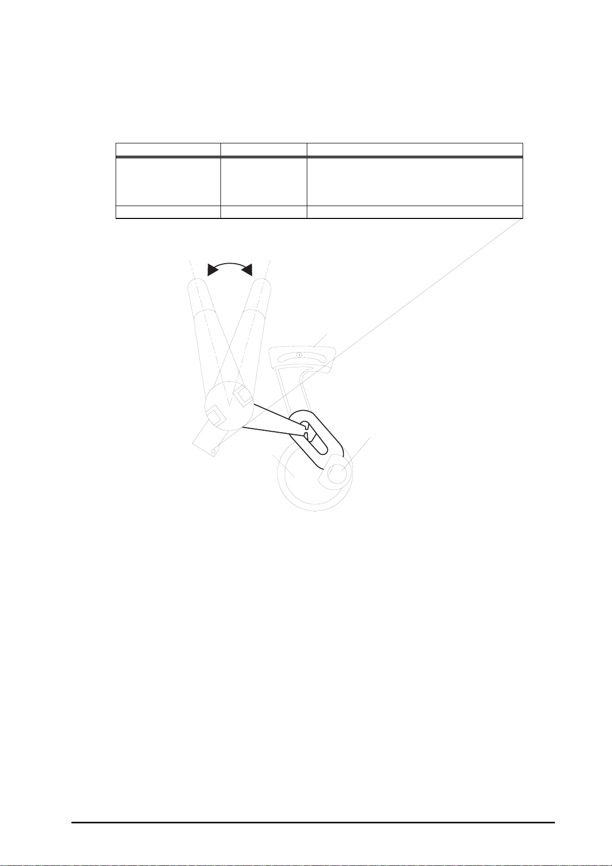
1.2.3 Adjust Lever Settings (PG adjust lever)
The adjust lever located on the right side (blue knob) under the printer cover needs to be set to the
proper position according to the paper you print (Refer to the table below). Also, if there is any dirt
caused by friction on the wavy or wrinkled paper, this can be prevented by changing the lever position to
rear position (marked with “+”) in spite of paper types.
Table 1-5. Adjust Lever Settings
Paper Lever position PG adjustment value
Normal paper,
Coated paper
Transparency film
Label
Envelopes Rear 0.9 mm (2.0mm between head and platen)
Front (Mark "0")
Front 0 mm (1.1mm between head and platen)
+
Rear (Mark "
")
Level adjustment lever
CR Guide Shaft
Bush
Figure 1-2. Adjust Lever Settings
1-
Rev. A
Page 14
Chapter 1 Product Description
7
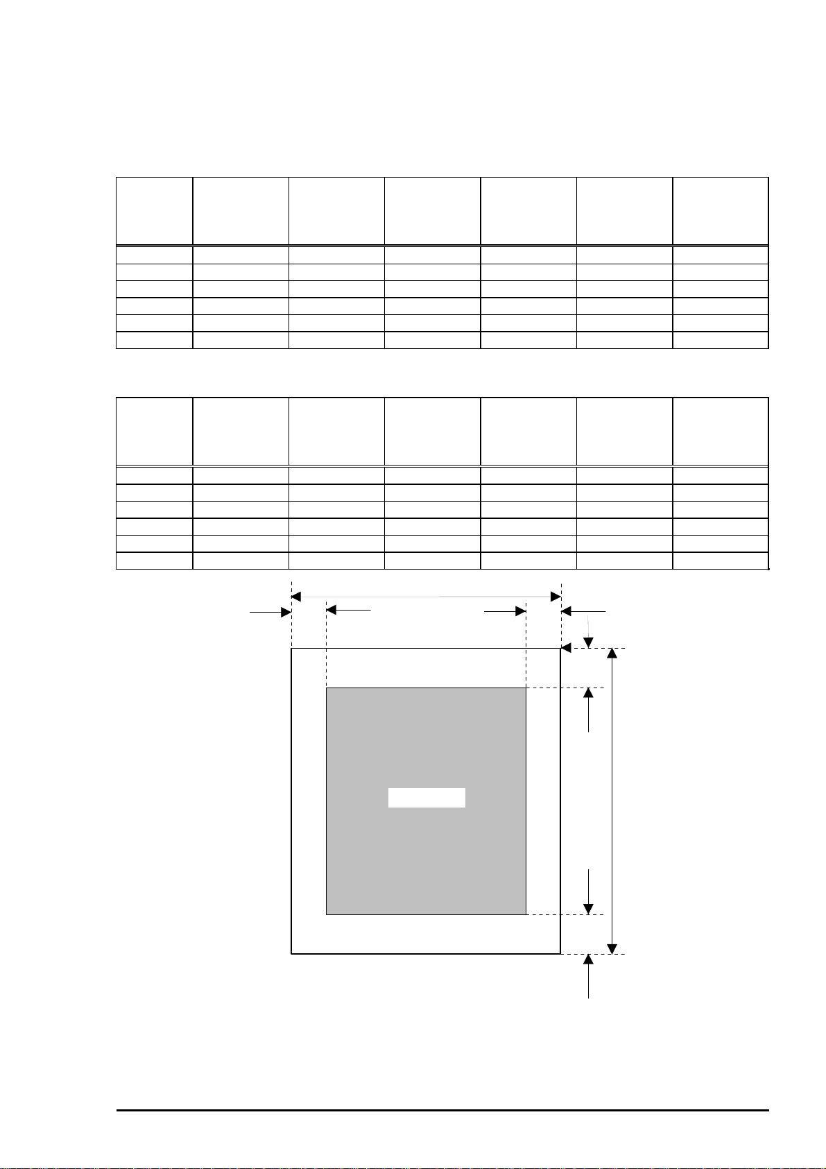
1.2.4 Printable Area
1.2.4.1 Cut Sheet
Following tables show printable areas at Character mode and Raster Graphics mode.
Table 1-6. Character Table
Paper size PW
(Paper width)
(typ.)
PL
(Paper
Length)
(typ.)
LM
(Left margin)
(min.)
RM
(Right
margin)
(min.)
TM
(Top margin)
(min.)
BM
(Bottom
margin)
(min.)
A4 210mm(8.3”) 297mm(11.7”) 3mm(0.12”) 3mm(0.12”) 3mm(0.12”) 14mm(0.54”)
Letter 216mm(8.5”) 279mm(11.0”) 3mm(0.12”) 9mm(0.35”) 3mm(0.12”) 14mm(0.54”)
B5 182mm(7.2”) 257mm(10.1”) 3mm(0.12”) 3mm(0.12”) 3mm(0.12”) 14mm(0.54”)
Legal 216mm(8.5”) 356mm(14.0”) 3mm(0.12”) 9mm(0.35”) 3mm(0.12”) 14mm(0.54”)
Statement 139.7mm(5.5”) 215.9mm(8.5”) 3mm(0.12”) 3mm(0.12”) 3mm(0.12”) 14mm(0.54”)
Executive 190.5mm(7.5”) 254mm(10”) 3mm(0.12”) 3mm(0.12”) 3mm(0.12”) 14mm(0.54”)
Table 1-7. Raster Graphics Mode
Paper size PW
(Paper width)
(typ.)
PL
(Paper
Length)
(typ.)
LM
Left margin)
(min.)
RM
(Right
margin)
(min.)
TM
(Top margin)
(min.)
BM
(Bottom
margin)
(min.)
A4 210mm(8.3”) 297mm(11.7”) 3mm(0.12”) 3mm(0.12”) 3mm(0.12”) 14mm(0.54”)
Letter 216mm(8.5”) 279mm(11.0”) 3mm(0.12”) 3mm(0.12”) 3mm(0.12”) 14mm(0.54”)
B5 182mm(7.2”) 257mm(10.1”) 3mm(0.12”) 3mm(0.12”) 3mm(0.12”) 14mm(0.54”)
Legal 216mm(8.5”) 356mm(14.0”) 3mm(0.12”) 3mm(0.12”) 3mm(0.12”) 14mm(0.54”)
Statement 139.7mm(5.5”) 215.9mm(8.5”) 3mm(0.12”) 3mm(0.12”) 3mm(0.12”) 14mm(0.54”)
Executive 190.5mm(7.5”) 254mm(10”) 3mm(0.12”) 3mm(0.12”) 3mm(0.12”) 14mm(0.54”)
PW
LM RM
Printable Area
Figure 1-3. Printing Area for Cut Sheet
TM
PL
BM
Rev. A
1-
Page 15
EPSON Stylus Color 600
8
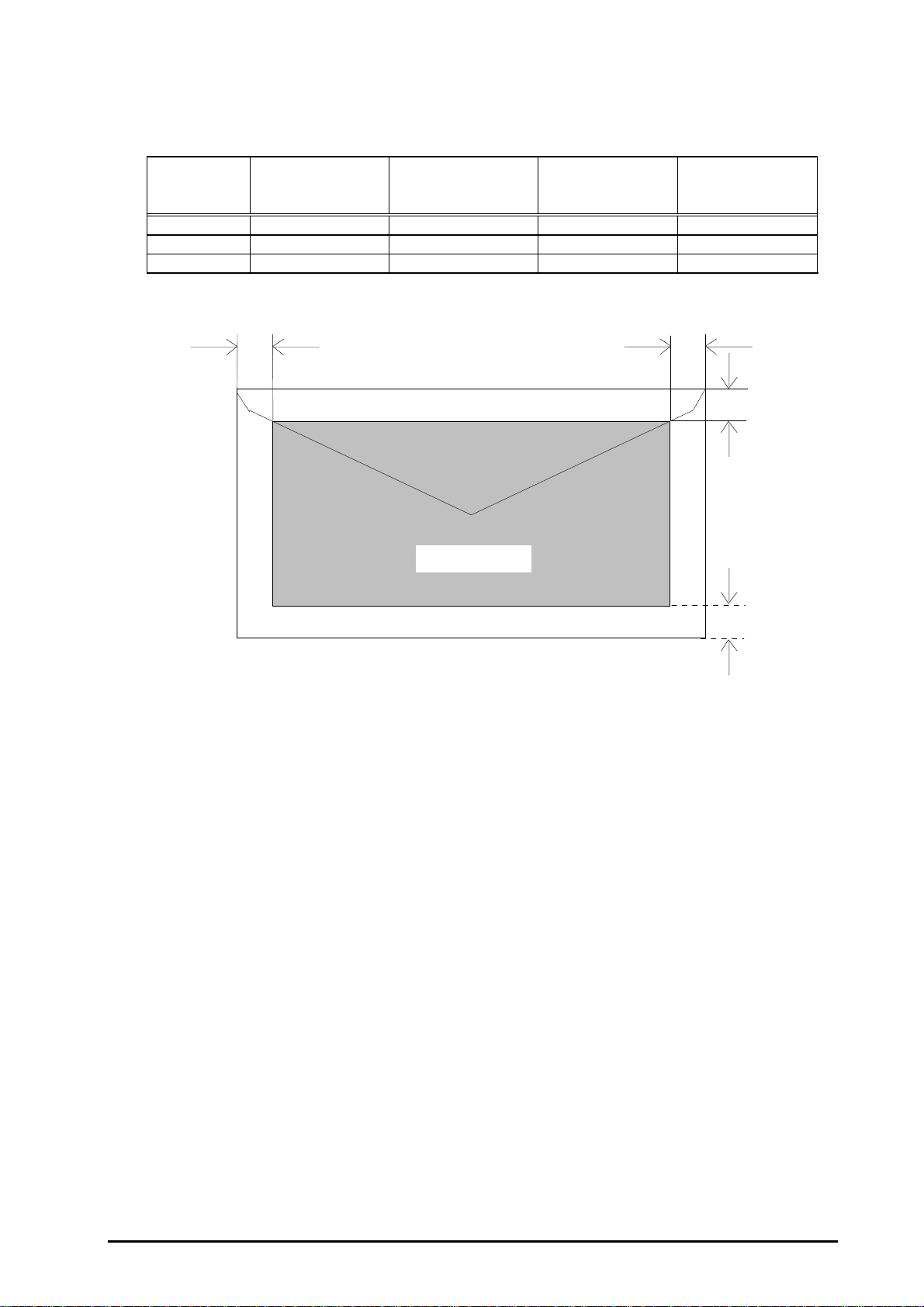
1.2.4.2 Envelope
The table and figure below show the printable area for envelopes.
Table 1-8. Envelope
Paper Size LM
(Left Margin)
(min.)
#10 3mm (0.12”) 28mm (1.10”) 3mm (0.12”) 14mm (0.55”)
DL 3mm (0.12”) 7mm (0.28”) 3mm (0.12”) 14mm (0.55”)
C6 3mm (0.12”) 3mm (0.12”) 3mm (0.12”) 14mm (0.55”)
LM
RM
(Right Margin)
(min.)
Printable area
TM
(Top Margin)
(min.)
(Bottom Margin)
RM
BM
(min.)
TM
Figure 1-4. Printing Area for Envelope
BM
1-
Rev. A
Page 16
Chapter 1 Product Description
9
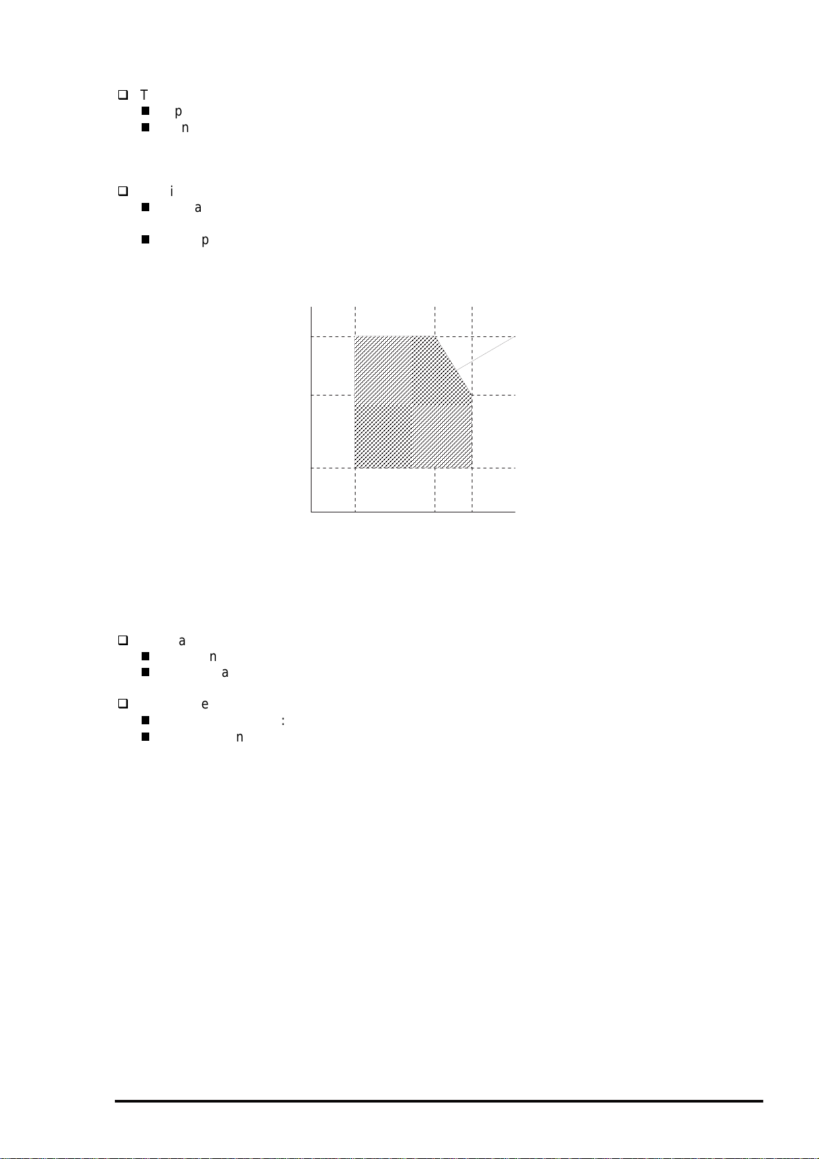
1.2.5 Environmental Condition
Temperature
Operating :10 - 35•• (Refer to the figure below for condition)
Non-operating :-20 - 60•• (with shipment container)
Note) Storage should be within one month at 40°C and 120 hours at 60°C.
Humidity
Operating :20% - 80% RH
(without condensation. Refer to the figure below for condition)
Non-operating :5% - 85% RH
(without condensation and with shipment container)
Humidity
(% RH)
80%
55%
Guaranteed range
20%
10°C
(50°F)
27°C
(80°F)
35°C
(95°F)
°C
(°F)
Figure 1-5. Temperature/Humidity of Range
Resistance to shock
Operating :1G, within 1 ms (X,Y,Z directions)
Non-operating :2G, within 2 ms (X,Y,Z directions/with shipment container)
Resistance to vibration
Operating :0.15G, 10•`55Hz (X,Y,Z directions)
Non-operating :0.50G, 10•`55Hz (X,Y,Z directions/with shipment container)
Note) 1. During non-operating, make sure that the head is capped.
2. During the transport, make sure that the head is capped and ink cartridge is installed to the
printer.
3. If the head is not capped at the power-off state, turn the power on with the ink cartridge
installed and turn off the power after confirming that the head is correctly capped.
4. Ink will be frozen under -4°C environment, however it will be useable after placing it more than
3 hours at 25°C.
Rev. A
1-
Page 17
EPSON Stylus Color 600
0
1.2.6 Ink Cartridge Specifications
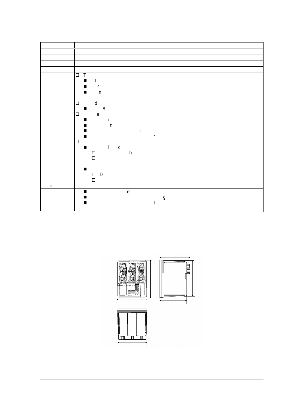
1.2.6.1 Black Ink Cartridge
Table 1-9. Black Ink Cartridge Specifications
Item Specifications
Type Black Ink Cartridge (Code: S020093)
Color Black
Print capacity 540 pages / A4 (ISO/IE10561 Letter Pattern at 360 dpi)
Validity 2 years (sealed in package) / 6months(out of package)
Environmental
conditions
Dimension 19.8mm(W) x 52.7(D) x 38.5mm(H)
Weight
Temperature
Storage :-20 - 40°C (within a month at 40°C)
Packing storage :-30 - 40°C (within a month at 40°C)
Transit :-30 - 60°C (within 120 hours at 60°C and within a
month at 40••)
Humidity
5% - 85% (without condensation)
Resistance to vibration
Sealed in package :5 - 55Hz
Acceleration :Less than 29.4m/s (3G)
Direction :X, Y, Z direction
Time :1 hour
Drop
Sealed in package:
Dropping height :Less than 0.80m
Direction :Drop the package facing the bottom, sides and one
edge down.
Out of package:
Dropping height :Less than 1.50m
Frequency :Once
Total ink cartridge :54g
Total ink :16.4•}0.5g (Amount in the ink cartridge)
Consumable ink :More than 12.1g(Useable ink quantity until ink ends)
Note) 1. Ink cartridge can not re-fill, only ink cartridge is prepared for article of consumable.
2. Do not use the ink cartridge which is passed away the ink life.
3. Ink will be frozen under -4••environment, however it will be usual after placing it more than 3
hours at room temperature.
19.8
52.7
38.5
18.3
51.2
Figure 1-6. Ink Cartridge (Black)
1-1
Rev. A
Page 18
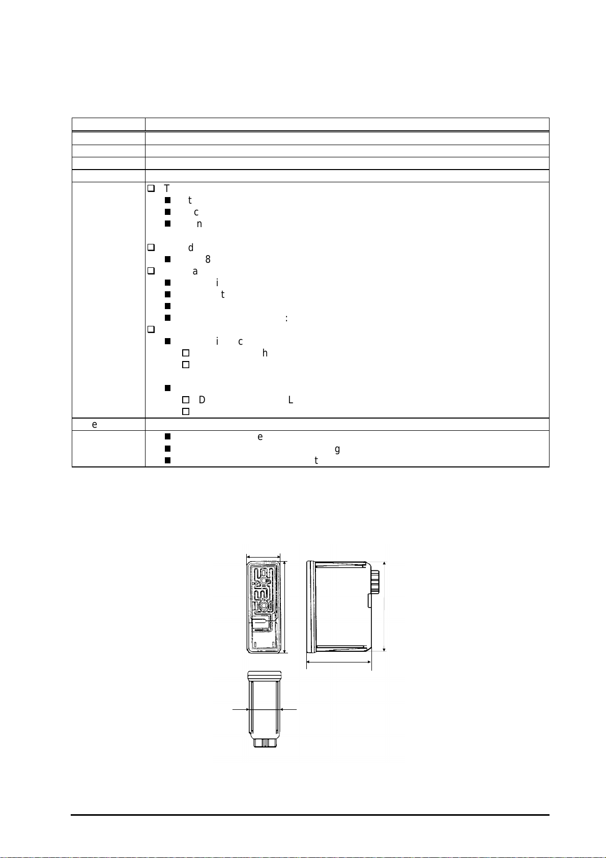
1.2.6.2 Color Ink Cartridge
Table 1-10. Color Ink Cartridge Specification
Item Specifications
Type Color Ink Cartridge(Code: S020089)
Color Magenta/Cyan/Yellow
Print capacity 300 pages / A4 (360 dpi, 5% duty each color)
Validity 2 years (sealed in package) / 6months(out of package)
Environmental
conditions
Dimension 42.9mm(W) x 52.7(D) x 38.5mm(H)
Weight
Temperature
Storage :-20•• - 40•• (within a month at 40••)
Packing storage :-30•• - 40•• (within a month at 40••)
Transit :-30•• - 60•• (within 120 hours at 60••and within a
month at 40••)
Humidity
5% - 85% (without condensation)
Resistance to vibration
Sealed in package :5 - 55Hz
Acceleration :Less than 29.4m/s (3G)
Direction :X, Y, Z direction
Time :1 hour
Drop
Sealed in package :
Dropping height :Less than 0.80m
Direction :Drop the package facing the bottom, sides and one
edge down.
Out of package:
Dropping height :Less than 1.50m
Frequency :Once
Total ink cartridge :68g
Total ink :13.3•}0.5g (Amount in the ink cartridge)
Consumable ink :More than 10.1g/each color (Useable ink quantity until
ink ends)
Chapter 1 Product Description
Note)
1. Ink cartridge can not re-fill, only ink cartridge is prepared for article of consumable.
2. Do not use the ink cartridge which is passed away the ink life.
3. Ink will be frozen under -4••environment, however it will be usual after placing it more than 3
hours at room temperature.
43.2
51.2
42.9
41.4
52.7
38.5
Figure 1-7. Ink Cartridge (Color)
Rev. A
1-11
Page 19
EPSON Stylus Color 600
2
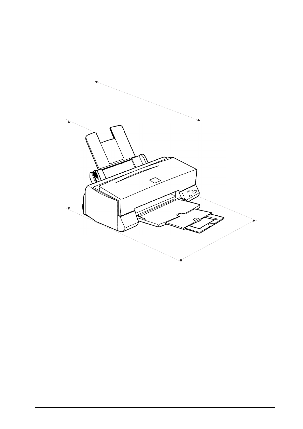
1.2.7 Physical Specification
[Dimension]
[Weight]
309mm
:429mm(W) x 234mm(D) x 162mm(H)
:429mm(W) x 695mm(D) x 309mm(H) with extended stacker and paper support.
:5.2Kg
695mm (Max)
Figure 1-8. Dimension
429mm
1-1
Rev. A
Page 20
3
1.2.8 Electric Specification
[120V] Version
[Rated voltage] :AC120V
[Input voltage range] :AC103.5 - 132V
[Rated frequency range] :50 - 60Hz
[Input frequency range] :49.5•`60.5Hz
[Rated current] :0.4A(Max. 0.5A)
[Power consumption] :Approx.15W(ISO/IEC 10561 Letter pattern)
[Insulation Resistance] :10M ohms min.(between AC line and chassis, DC500V)
[Dielectric strength] :AC1000 V rms. 1 minute or AC1200Vrms. 1 second
(Energy Star compliant)
(between AC line and chassis)
Chapter 1 Product Description
[220•`240V] Version
[Rated voltage] :AC220V - 240V
[Input voltage range] :AC198 - 264V
[Rated frequency range] :50 - 60Hz
[Input frequency range] :49.5 - 60.5Hz
[Rated current] :0.2 A(Max. 0.3A)
[Power consumption] :Approx.15W(ISO/IEC 10561 Letter pattern)
[Insulation Resistance] :10M ohms min.(between AC line and chassis, DC500V)
[Dielectric strength] :AC1500 V rms. 1 minute (between AC line and chassis)
1.2.9 Reliability
Total print volume :10,000 pages(A4, letter)
Print head life :2000 million dots/nozzle
1.2.10 Safety Approvals
[120V version]
Safety standard :UL1950 with D3
EMC :FCC part 15 subpart B class B
(Energy Star compliant)
:CSA22.2 No.950 with D3
:CSA C108.8 class B
[220•`240V]
Safety standard :EN 60950(VDE and NEMKO)
EMC :EN55022(CISPR Pub.22) class B
1.2.11 Acoustic Noise
Noise Level :Approx.45 dB(A) (According to ISO 7779)
1.2.12 CE Marking
[220-240V version]
Low voltage Directive 73/23/EEC :EN60950
EMC Directive 89/336/EEC :EN55022 Class B
:AS/NZS 3548 class B
:EN61000-3-2
:EN61000-3-3
:EN50082-1
:IEC801-2
:IEC801-3
:IEC801-4
Rev. A
1-1
Page 21
EPSON Stylus Color 600
4
1.2.13 Printer Language and Emulation
Printer Language :ESC/P2
:EPSON Remote
ESC/P control codes
General Operation:
Initialize Printer : ESC @
Unidirectional Printing : ESC U
CSF Mode Control : ESC EM
Paper feeding:
Form Feed : FF
Line Feed : LF
Line Spacing : ESC 0, ESC 2, ESC 3, ESC +
Carriage Return : CR
Page format:
Page Length :ESC (C, ESC C, ESC C0
Left / Right Margin :ESC Q, ESC1
Top / Bottom Margin :ESC (c, ESC N, ESC O
Printer position motion:
Horizontal Print Position :ESC $, ESC\
Vertical Print Position :ESC(V, ESC (v
Tab Horizontally :ESC D, HT
Tab Vertically :ESC B, VT
Advance paper :ESC J
Font Selection:
Typeface :ESC k, ESC x
Pitch and Point :ESC X
Pitch :ESC P, ESC M, ESC g, ESC p
Italic Font :ESC 4, ESC 5
Bold Font :ESC E, ESC F
Master Select :ESC!
Font enhancement:
Double-Width :ESC W, DC4, SO
Condensed :DC2, SI
Double-height :ESC w
Double-Strike :ESC G, ESC H
Super / Subscript :ESC T, ESC S
Underline :ESC-
Line / Score :ESC(-
Character Style :ESC q
Spacing:
Intercharacter Space :ESC Space
HMI :ESC c
Define Unit :ESC (U
Character handling:
Character Table :ESC t, ESC (t
International Character :ESC R
User-Defined Characters :ESC %, ESC &, ESC:
Upper Control Codes :ESC 6, ESC7
Print Data as Characters :ESC(^
1-1
Rev. A
Page 22
5
Bit image:
Bit Image :ESC*
Graphics:
Graphics Mode :ESC (G
Raster Graphics :ESC.
Microweave control :ESC (i
Dot size control :ESC (e
Horizontal Position :ESC (\
Printing Speed :ESC(s
Printing mode:
Printing mode :ESC (K
Color:
Printing Color :ESC r, ESC (r
EEPROM control
EEPROM control :ESC
Chapter 1 Product Description
Rev. A
1-1
Page 23
EPSON Stylus Color 600
6
1.3 Interface
This printer provides both parallel and serial interface as standard.
1.3.1 Parallel Interface (Forward Channel)
[Transmission mode]
[Synchronization]
[Handshaking]
[Signal level]
[Adaptable connector]
BUSY signal is set high before setting either/ERROR low or PE high and held high until all these signals
return to their inactive state.
BUSY signal is at high level in the following cases.
During data entry (see Data transmission timing)
When input data buffer is full
During -INIT signal is at low level or during hardware initialization
During printer error (See /ERROR signal)
When the parallel interface is not selected.
ERROR signal is at low level when the printer is in one of the following states.
Printer hardware error (fatal error)
Paper-out error
Paper-jam error
Ink-out error
:8 bit parallel, IEEE-1284 compatibility mode
:By /STROBE pulse
:BY BUSY and /ACKNLG signal
:TTL compatible level
:57-30360 (amphenol) or equivalent
PE signal is at high level during paper-out error.
Table 1-11 shows the signal and connector pin assignments for parallel interface(forward channel*1). In
case of these signals, twist pair line is used and returning side is connected to signal GND (*1). Forward
channel is the mode when the ordinary data such as print data is sent from the PC to the printer.
Table 1-11. Signal and Connector Pin Assignment for Parallel Interface
Pin No. Signal Name Return GND
pin
1 /STROBE 19 In The strobe pulse. Read-in of data is performed at
2-9 DATA0-7 20-27 In The DATA0 through DATA7 signals represent
10 /ACKNLG 28 Out This signal is a negative pulse indicating that the
11 BUSY 29 Out A high signal indicates that the printer cannot
12 PE 28 Out A high signal indicates paper-out error.
13 SLCT 28 Out Always at high level when the printer is powered
14 /AFXT 30 In Not used.
31 /INIT 30 In The falling edge of a negative pulse or a low
32 /ERROR 29 Out A low signal indicates printer error condition.
36 /SLIN 30 In Not used.
18 Logic H - Out Pulled up to +5V via 3.9K ohm resistor.
35 +5V - Out Pulled up to +5V via 3.3K ohm resistor.
17 Chassis GND - - Chassis GND.
16,33,19-30 GND - - Signal GND.
15,34 NC - - Not connected.
I/O Functional Description
the falling edge of this pulse.
data bits 0 to 7, respectively. Each signal is at
high level when data is logical 1 and low level
when data is logical 0.
printer can again accept data.
receive data.
on.
signal on this line causes the printer to initialize.
Minimum 50 us pulse is necessary.
Note) “I/O” refers to the direction of signal flow from the printer’s point of view.
1-1
Rev. A
Page 24
7
1.3.2 Parallel Interface (Reverse Channel)
[Transmission mode]
[Synchronization]
[Handshaking]
[Data transmission timing]
[Signal level]
[Adaptable connector]
[Extensibility request]
Note) The printer sends following device ID string when it is requested.
:IEEE-1284 nibble mode
:Refer to the IEEE-1284 specification
:Refer to the IEEE-1284 specification
:Refer to the IEEE-1284 specification
:IEEE-1284 level 1 device
:TTL compatible level
:57-30360 (amphenol) or equivalent
:The printer responds affirmatively when the extensibility request values
are 00H or 04H, that mean;
00H :Request Nibble Mode Reverse Channel Transfer.
04H :Request device ID; Return Data using Nibble Mode Rev Channel
Transfer.
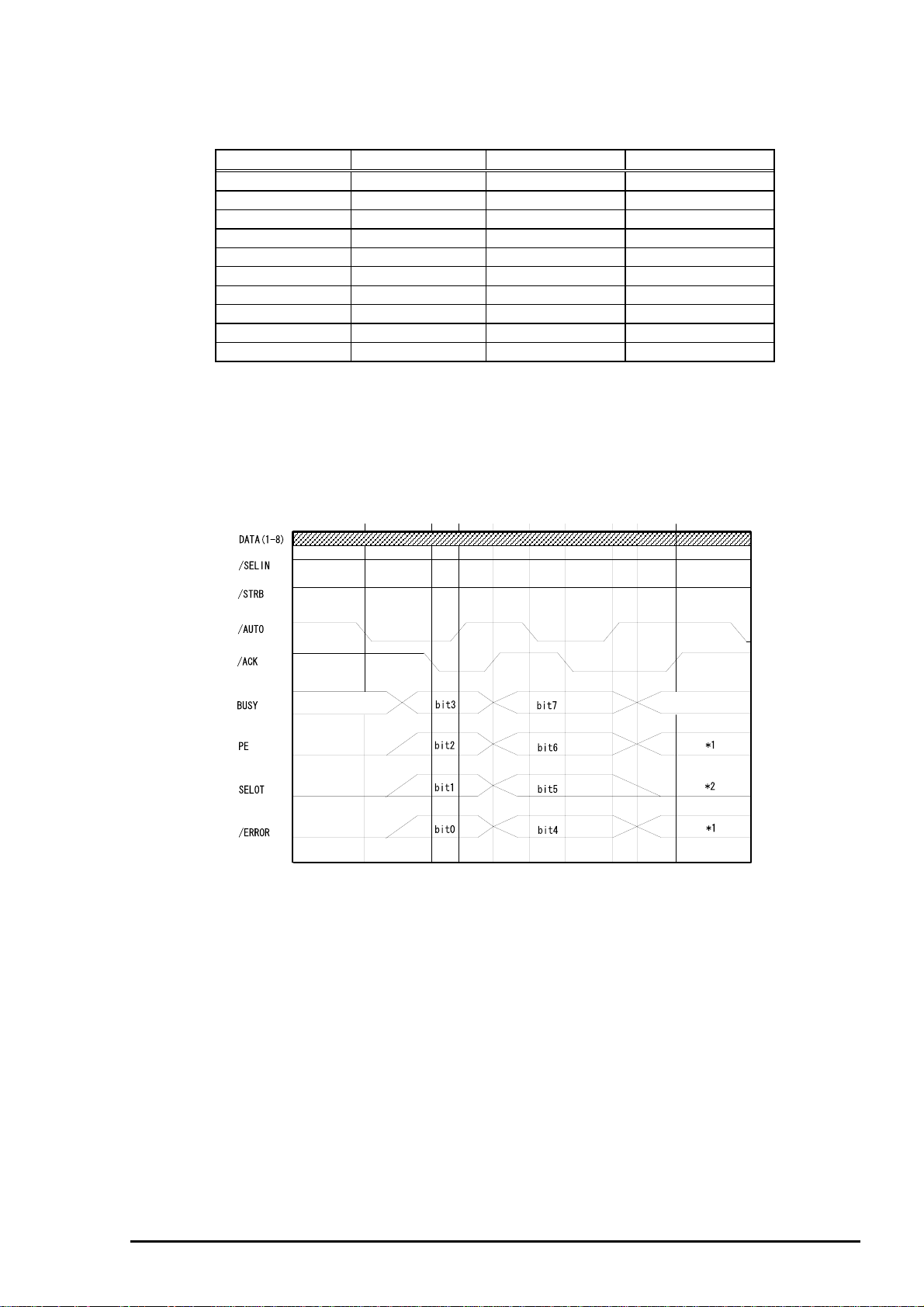
Table 1-12. Device ID Description
Chapter 1 Product Description
•q
The table below shows pin assignment for reverse channel(*3). In these case of signals, twist pair line is
used and returning side is connected to Signal GND. (*3):Reverse channel is the mode that any data is
transferred from the printer to the PC.
Pin
No.
1 HostClk 19 In Host clock signal.
2-9 Data0-7 20-27 In The DATA0 through DATA7 signals represent data bits 0
10 PrtClk 28 Out Printer clock signal.
11 PtrBusy, Data Bit-3,7 29 Out Printer busy signal and reverse channel transfer data bit
12 AckDataReq, DataBit-2,6 28 Out Acknowledge data request signal and reverse channel
13 Xflag, DataBit-1,5 28 Out X-flag signal and reverse channel transfer data bit 1 or 5.
14 HostBusy 30 In Host busy signal.
31 /INIT 30 In Not used.
32 /DataAvail, DataBit-0,4 29 Out Data available signal and reverse channel transfer data
36 1284-Active 30 In 1284 active signal.
18 Logic-H - Out Pulled up to +5V via 3.9K ohm resister.
35 +5V - Out Pulled up to +5V via 3.3K ohm resister.
17 Chassis GND - - Chassis GND.
16,33
19-30
15, 34 NC - - Not connected.
[00H] denotes a hexadecimal value of zero. MDL value depends on the EEPROM setting.
MDL value depends on the EEPROM setting. Model name can be changed by
changing a certain address in the EEPROM.
Table 1-13. Pin Assignment for Reverse Channel
Signal Name Return
•r •q
00H
MFG EPSON Production Maker
CMD ESCPL2,BDC Command system
MDL Stylus[SP]Color[SP] 600 Model name
CLS PRINTER Class
GND pin
GND - - Signal GND.
•r
3CH
I/O Functional description
to7, respectively.
Each signal is at high level when data is logical 1 and
low level when data is logical 0. These signals are used
to transfer the 1284 extensibility request values to the
printer.
3 or 7.
transfer data bit 2 or 6.
bit 0 or 4.
Contents
Note) “I/O” refers to the direction of signal flow from the printer’s point of view.
Rev. A
1-1
Page 25
EPSON Stylus Color 600
8
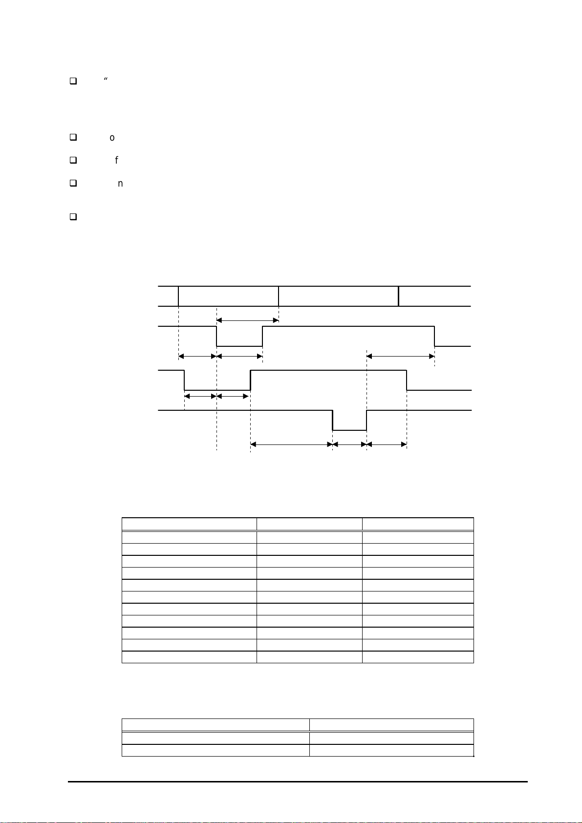
Following lists “Notes” when using Parallel Interface.
“
Return GND pin” in the table means twist pair return and is used for all control signals except for
Logic H,+5V, Chassis, GND and NC. In this twist pair return, returning side is connected to
GND (16,33, 19-30 pin) for twist pair return. Also, these cables are shielded wires and it is
effective to connect to each chassis GND in the PC and printer for electrostatic noise.
Conditions for Interface are based on TTL level. Rise and fall time should be within 0.2ms.
Refer to the figure 1-9 for transmission timing of each signals.
Do not perform data transmission ignoring /ACK or BUSY signal. (Perform the data transmission
after confirming that /ACK and BUSY signals are Low.)
It is possible to perform the printing test including interface circuit without using equipment from
outside when 8-bit data signal(20-27 pin) is set to appropriate word code and connect them
forcefully to /ACK and /STRB.
[Data Transmission Timing for Forward Channel]
Data
/STROBE
BUSY
/ACKNLG
Byte Data n Byte Data n+1
Thold
Tsetup
Tstrb
Tready Tbusy
Tnext
Treply
Tack Tnbusy
Figure 1-9. Parallel Interface Timing Chart(Forward Channel)
Table 1-14. Timing Parameters and Value
Parameter Minimum Maximum
tsetup 500ns ---
thold 500ns ---
tstb 500ns ---
tready 0 ---
tbusy --- 500ns
tt-out* --- 120ns
tt-in** --- 200ns
treply 0 ---
tack 500ns 10us
tnbusy 0 ---
tnext 0 ---
Note) *: Rise and fall time of every output signals.
**: Rise and fall time of every input signals.
Table 1-15. Typical Time of Tack
Parallel I/F mode Typical time of tack
High speed 2us
Normal speed 4us
1-1
Rev. A
Page 26
Chapter 1 Product Description
9
[Signal level: TTL compatible (IEEE-1284 level 1 device)]
Table 1-16. Signal Level
Parameter Minimum Maximum Condition
VOH* --- 5.5V
VOL* -0.5V ---
IOH* --- 0.32mA VOH = 2.4V
IOL* --- 12mA VOL = 0.4V
CO --- 50pF
VIH --- 2.0V
VIL 0.8V ---
IIH --- 0.32mA VIH = 2.0V
IIL --- 12mA VIL = 0.8V
CI --- 50pF
Note) *: A low logic level on the Logic H signal is 2.0V or less when the printer is
powered off and this signal is equal or exceeding 3.0V when the printer is
powered on. The receiver shall provide an impedance equivalent to
7.5K ohm to ground.
[Data Transmission Timing for Reverse Channel]
The figure below shows timing chart of Parallel Interface Reverse channel.
Virtual Busy Status
Virtual Busy Status
Figure 1-10. Parallel Interface Timing Chart(Reverse Channel)
1.3.2.1 Prevention Hosts from Data Transfer time-out
Generally, hosts abandon data transfer to peripherals when a peripheral is in the busy state for dozens of
seconds continuously. To prevent hosts this kind of time-out, the printer receives data very slowly,
several bytes per minute, even if the printer is in busy state. This showdown is started when the rest of
the input buffer becomes several hundreds of bytes. Finally, the printer is in the busy state continuously
when the input buffer is full.
Rev. A
1-1
Page 27
EPSON Stylus Color 600
0
1.3.3 Serial Interface
[Standard] :Based on RS-423
[Synchronization] :Synchronous
[Bit Rate] :Approx. 900Kbps
[Handshaking] :X-ON/X-OFF, DTR Protocol
[Word Format] :Data Bit = 8 bits
:Parity Bit = None
:Start Bit = 1 bit
:Stop Bit = 1 bit
[Connector] :8-pin mini-circular connector
[Recommended Cable] :Apple System Peripheral-8 Cable
(Part #: M0197)
Table 1-17. Pin Assignment
Pin No. Signal Name I/O Description
1 SCLK O Synchronous clock signal
2 CTS I Clear To Send
3 TXD- O Transmit Data (-)
4 SG I (Signal Ground)
5 RXD- I Receive Data (-)
6 TXD+ O Balanced Transmit Data (+)
7 DTR O Data Terminal Ready
8 RXD+ I Balanced Receive Data (+)
Table 1-18. X-ON/X-OFF and DTR Status
State Buffer Space X-ON/X-OFF DTR
Busy Less than 3072 bytes Send X-OFF code OFF
Ready More than 5120 bytes Send X-ON code ON
1-2
Rev. A
Page 28
Chapter 1 Product Description
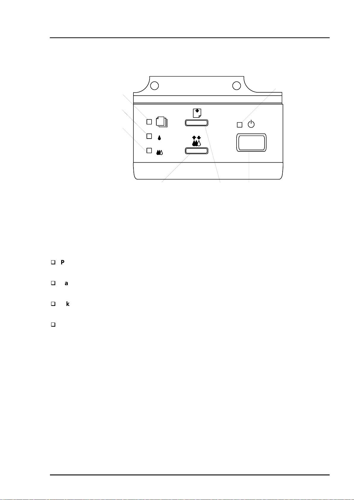
1.4 Control Panel
Since EPSON Stylus Color 600 does not require many buttons since printer driver can start various
settings and motions. Therefore, there are only 2 non-lock type push switches, 1 lock type push switch
and 4 LEDs.
Following figure shows control panel of EPSON Stylus Color 600.
Paper out LED
Ink out(Black)LED
Ink out(CMY)LED
1.4.1 Indicators
Cleaning Switch
(Ink maintenance)
Figure 1-11. Control Panel
Load/Eject switch
Power
Power switch
LED
Power
Lights when the operate switch is “ON”, and AC power is supplied.
Paper out
Lights during the paper-out condition, and blinks during the paper-jam condition.
Ink Out (Black)
Lights during no Black ink condition, and blinks during the Black ink low condition.
Ink Out (Color)
Lights during no Color ink condition, and blinks during the Color ink low condition.
Rev. A
1-21
Page 29
EPSON Stylus Color 600
2
1.4.2 Panel Functions
•q
Panel Functions
Switch Function
Load/Eject
(Pushing within 0.5 seconds*)
Load/Eject
(Pushing for 2 seconds*)
Cleaning
(Pushing for 2 seconds*)
Cleaning
(Pushing within 2 seconds*)
Note) *: 3 seconds is required at the User’s manual.
**: This function is not available in printing status.
***: The time to complete the sequence may vary depending on the printer’s status.
•r
Table 1-19. Panel Function
Loads or Eject the paper.
When the carriage is on the Ink Cartridge change position, return the
carriage from Ink Cartridge change position.
Starts the Ink Cartridge change sequence.**
Moves the carriage to cartridge change position.
Starts the Head Cleaning sequence. ***
In the condition of “Ink Low” or “Ink Out” or “No Ink Cartridge” starts
the Ink Cartridge change sequence.**
When carriage is on the Ink Cartridge change position, return carriage
from Ink Cartridge change position.
•q
Panel Functions with Power ON
Table 1-20. Panel Function with Power ON
Switch Function
Load/Eject
Cleaning
Load/Eject
+
Cleaning
•r
Starts status printings.**
Enter the Default Setting mode
Enters the particular settings mode. (Factory use only.)
To enter the particular settings mode, it is necessary to push
followings switch while Paper Out LED is blinking.(It blinks about 5
seconds)
Note) **: status printings prints firmware version, ink counter, selected code page and nozzle check
patterns.
•q
Particular setting mode
Switch Function
Load/Eject
•r
Table 1-21. Particular Setting Mode
Initialize EEPROM *** and reset Timer IC.
Note) ***: Refer to EEPROM map.
1-2
Rev. A
Page 30
Chapter 1 Product Description
3
By performing a particular setting mode, Maintenance error can be cleared and certain addresses of
EEPROM can also be reset.
[Step 1] Turn the printer on while holding down Load/Eject and Cleaning switches at the same time.
[Step 2] Push the Load/Eject switch while the Paper Out LED is blinking (5 seconds).
Following shows the lists that will be cleared by this performance.
Maintenance Error Clear
(By operating this performance, the Paper Out LED starts blinking.)
Clear the value of Ink Counter
Clear Time IC
Initialization of I/F selection (returns to AUTO)
WARNING
EPSON Stylus Color 600 does not have “EEPROM All Clear” function like other printers. If the
printer does not function well and falls into fatal error condition, replace the main board to see if
the problem is rectified. (Refer to Chapter 4 “Adjustment” when you replace the main board since
some adjustments will be necessary.)
Be sure to replace a waste ink pad in the printer enclosure with a new one after you perform
Maintenance error clear operation.
1.4.3 Printer Condition and Panel Status
The table below shows printer condition and panel status. Since this table shows various error status and
also present printer status, you can judge appropriate repair ways from this table.
Table 1-22. Printer Condition and Panel Status
Printer status Indicators Priority
Power Ink Out
(Black)
Power on condition On --- --- --- 9
Ink sequence Blink --- --- --- 6
Ink Cartridge change mode Blink --- --- --- 5
Data processing Blink --- --- --- 8
Paper Out --- --- --- On 4
Paper jam condition --- Off Off Blink 3
No Ink cartridge or Ink end(black) --- On --- --- 7
Ink level low(black) --- Blink --- --- 7
No Ink cartridge or Ink end(color) --- --- On --- 7
Ink level low(color) --- --- Blink --- 7
Enter EEPROM and Timer IC reset --- On
(1 second
only)
Maintenance request Blink Blink Blink Blink 2
Fatal error Blink On On Blink 1
Ink Out
(Color)
On
(1 second
only)
Paper Out
On
(1 second
only)
--
Note) “—“ means no changes.
Rev. A
1-2
Page 31

EPSON Stylus Color 600
4
1.5 Error Status
When following status occur, the printer goes to the error status and stops taking data, setting the
/ERROR signal in the interface as “Low”, and Busy signal as “High”. At this time, the printer goes to non
printable status. Refer to section 1.4.2 for more details of LED Panel indicators during the various error
status.
1.5.1 Ink Out
When the printer runs out the most part of the ink of any one color, it warns ink-low and keeps printing.
When the printer runs out the whole ink of any one color, it stops printing and indicates ink-out error.
User is requested to install a new ink-cartridge in this state. An ink-cartridge once taken out should never
be used again. Re-installation of the cartridge not filled fully upsets the ink level detection and may
cause a serious problem in the print head as a result.
WARNING
Never use the ink cartridge once taken out from the printer.
Following explains the reason of the above warning.
After the cartridge is once taken out, airs come in from the ink supply hole located at the top of
cartridge and becomes bubbles, and they are absorbed into the head during printing performance.
Therefore, the head will be unable to discharge the ink properly. Also, inevitable entering of bubbles
when installing a new ink cartridge can be absorbed to ink itself since the ink itself in the cartridge is
deaerated during the production process. However, this absorbing ability can last only about one hour
after the cartridge is installed.
Even after the bubble absorbing ability described above stops, there is no worry about entering
bubbles as long as the ink cartridge is being installed to the printer. However, if the ink cartridge
which does not have absorbing ability any more is once removed from the printer, new coming
bubbles into the cartridge will never disappear naturally. These bubbles may cause not only printing
malfunction but also thickening ink. This thickened ink goes into the head and clogs ink path in the
head or nozzle and may cause serious head damage.
As standard specification for EPSON Stylus Color 600, ink consumption counter is reset when the ink
cartridge is removed. If an ink cartridge is removed and re-installed unnecessarily the value on the
ink consumption monitor which the user can check will be wrong and printer may keep printing
even though the ink cartridge is installed empty. This may cause head damage.
1.5.2 Paper Out
When printer fails to load a sheet after power on operation including timer-cleaning is done and
Load/Eject button on the FF command or operation panel is pressed, it goes paper out error.
1.5.3 Paper Jam
When printer fails to eject a sheet even after feeding motion is completed or Load/Eject button on the FF
command or operation panel is pressed, it goes paper jam error.
1-2
Rev. A
Page 32

5
1.5.4 No Ink-Cartridge Error
Following reasons can be the causes when printer goes this error mode.
Chapter 1 Product Description
according to the ink cartridge exchange operation.)
When the printer is turned on for the first time.
(This is a normal error state and it returns to the normal state after installing an ink cartridge
Ink cartridge exchange operation is done correctly. After the position of carriage is moved by
exchange operation, if the cleaning switch is pushed without installing ink cartridge or if the
carriage returns to the home-position automatically without doing any operation, it is considered
as
handling mistake. However, it returns to normal state by performing ink exchange operation again
and installing cartridge correctly.
If “No ink-cartridge error” appears even after the ink cartridge is installed, the printer must be
something wrong and around the sensor area in the carriage need to be repaired.
If sometimes printer can print normally but also sometimes “No ink-cartridge error” appears, the
printer must be something wrong. (Same reason as above)
1.5.5 Maintenance Request
When the total quantity of ink wasted through the cleanings and flushing reaches to the limit, printer
indicates this error and stops. The absorber in the printer enclosure is needed to be replaced with new
one by a service person. The ink quantity that is absorbed by the absorber (waste ink pad) is monitored
by the software counter as “total ink counter”. This counter is added by point system and absorber’s
maximum ability is set at the following reference value.
29500 X 0.012 ml = Approximately 301ml
However, considering dispersion of ink absorbing quantity and the number of using nozzles, ink total
value is calculated by the following formula.
1-point = 0.0102 ml (the value which is multiplied evaporating rate and 1-dot ink weight 0.02
ml)
29500 = Maximum point number (Maintenance error threshold)
301 X 1.1/63% = 526ml (but up to 532ml can be retained)
WARNING
When you perform self- test after completing repairs, it is possible to check the present value of total
ink counter and ink discharge conditions from all nozzles by performing status printing in the built-in
function. Therefore, make sure that the printer has enough value of total ink counter (if the number is
close to 29500 or not). If there is not enough value, the service man is required to judge if it is
necessary to clear EEPROM after replacing the absorber (waste ink pad) or not. Refer to section
1.3.1 if you need to perform EEPROM Clear.
1.5.6 Fatal Errors
When printer detects fatal errors such as carriage control error or CG access error, it goes to this error
mode. Refer to followings for each error.
Carriage control Error: Parallel adjustment malfunction, Home-position malfunction, Timing belt
tension malfunction, shortage of lubricant on the carriage guide shaft, etc.
CG Access Error: Short circuit, etc.
Rev. A
1-2
Page 33

EPSON Stylus Color 600
6
1.6 Printer Initialization
EPSON Stylus Color 600 has three kinds of initialization methods. Following explains each initialization.
Power-on initialization
This printer is initialized when turning the printer power on, or printer recognized the
cold-reset command (remote RS command). When printer is initialized, following action is
performed.
Initializes printer mechanism.
Clears input data buffer.
Clears print buffer.
Sets default values.
Operator initialization
This printer is initialized when turning the printer power on again within 10 seconds from last
power off, or printer recognize the /INIT signal (negative pulse) of parallel interface. When
the printer is initialized, following action is performed.
Cap the printer head.
Eject a paper.
Clears input data buffer.
Clears print buffer.
Sets default values.
Software initialization
The ESC@ command also initialize the printer. When printer is initialized, following action is
performed.
Clears print buffer.
Sets default values.
1.6.1 Initialization Settings
EPSON Stylus Color 600 initializes following settings when the initialization is performed. Also, if the
user changes the settings in the Panel setting, Default setting or Remote command setting, values or
settings which are possible to be stored are initialized as initialization settings.
Page position :Page heading location as present paper location
Line spacing :1/6 inch
Right margin position :80 lines
Left margin position :first line
Character pitch :10CPI
Printing mode :Text mode (Not Raster graphics mode)
1-2
Rev. A
Page 34

Chapter 1 Product Description
7
1.7 Main Components
EPSON Stylus Color 600 has following major units. Also, it is one of the major characteristics that the
bottom of the Printer mechanism plays the role as lower case at the same time.
Upper case
Printer Mechanism
C200 MAIN Board (Main control circuit board)
C206 PSB/PSE Board (Power supply circuit board)
C206 PNL Board (Control panel circuit board)
1.7.1 Printer Mechanism
Unlike EPSON’s previous ink jet printer mechanisms, one of the major characteristics of EPSON Stylus
Color 600 is that the printer has no Engage/Disengage mechanism in order to change over pump
mechanism and paper feeding mechanism. Instead, however, this change-over control is done by the
distinction between turning direction of PF motor and position of present carriage unit. Also, another
major characteristic is that print head is changed to be one unit combined with black and CMY. Nozzle
configuration for black is 64 nozzles (the nozzle pitch of each column is 90dpi and between two
consecutive nozzles in number (e.g. #1 and #2) is 180dpi). On the other hand, CMY nozzle has 32
nozzles (90dpi) for each color. Following figure shows exterior of mechanism.
CR Motor
Carriage
Rev. A
Control Panel
Hopper
(Exit paper tray)
PF Motor
*ASF is not shown in the above figure.
Figure 1-12. Exterior view of the Printer Mechanism
1-2
Page 35

EPSON Stylus Color 600
8
1.7.2 C200 MAIN Board
The C200 MAIN board controls whole mechanism operations and a data processing operation. Most of
the functions of the circuit are integrated into single ASIC; E05B43YA (IC2) and this makes the board
design very simple and reliable.
IC7
Printhead Driver
IC15
PF Motor Driver
IC14
CR Motor Driver
IC2
ASIC
(E05B43YA)
IC1
CPU
(TMP95C0618F)
IC5
DRAM(4MBit)
IC6
Mask ROM (CG)
Parallel I/F(CN1)
Serial I/F (CN2)
IC3
PROM(4MBit)
Lithium Battery
Figure 1-13. Exterior view of C200 Main Board
1-2
Rev. A
Page 36

Chapter 1 Product Description
9
1.7.3 C206 PSB/PSE Board
The C206 PSB/PSE board is a switching regulator type power supply unit and constantly supplies stable
logic and power voltages to the printer mechanism and the main control board. Also, since this C206
PSB/PSE board has the power switch in the secondly side of the circuit, it is possible to keep supplying
electricity to the C200 MAIN control board for 30 seconds even after the power switch is turned off. Using
this time difference, even when mis-operation is done by the user such as turning off the power during
the middle of printing work, it prevents unexpected trouble with the printhead from occurring, by
transferring the printhead to the cap position before complete shut down. The C206 PSB Board is for
AC100 - 120V input voltage and the C206 PSE Board is for AC220 - 240V input voltage.
FUSE (F1)
AC input (CN1)
Q1
FET (Switching)
Power line to
C200 MAIN/Mechanism
(CN2)
PC1
Photo-coupler
Figure 1-14. Exterior view of C206 PSB Power Supply Board
1.7.4 C206 PNL Board
The C206 PNL board is located in the panel case where is in the right bottom of the front of printer and
consists of 3 switches, 4 LEDs.
Figure 1-15. Exterior view of C206 PNL Board
Rev. A
1-2
Page 37

Chapter 2
Operating Principles
2.1 OVERVIEW............................................................................................................2-1
2.1.1 Printer Mechanism............................................................................................................ 2-1
2.1.1.1 Printing Mec hanism.............................................................................................. 2-2
2.1.1.1.1 Printing Process......................................................................................... 2-3
2.1.1.1.2 Printing Method......................................................................................... 2-4
2.1.1.2 Carriage Mechanism............................................................................................. 2-7
2.1.1.2.1 Platen Gap Adjust Mechanism and P ar allel adjustment M ec hanism..........2-10
2.1.1.3 Paper Feed M ec hanism and Pum p M ec hanism...................................................2-11
2.1.1.4 Ink System ..........................................................................................................2-14
2.1.1.4.1 P ump, Carriage Lock, Head Cleaner M ec hanism......................................2-15
2.1.1.4.2 Cap M ec hanism........................................................................................
2.2 Electrical Circuit Operating Principles.............................................................2-18
2.2.1 C206 PSB/PSE Pow er Board ...........................................................................................2-19
2.2.2 C200 Main Board..............................................................................................................2-21
2.2.2.1 Reset Circuits......................................................................................................2-23
2.2.2.2 Sensor Circuits....................................................................................................2-24
2.2.2.3 EEPROM Cont rol Circuit s....................................................................................2-25
2.2.2.4 Timer Circuit........................................................................................................2-26
2.2.2.5 DRA M Control .....................................................................................................2-26
2.2.2.6 Pri nt Head Control Circuit....................................................................................2-27
2.2.2.7 PF(Pump) Motor Drive Circuit .............................................................................2-30
2.2.2.8 CR Motor Drive Circuit ........................................................................................2-31
2-17
Page 38

Chapter2 Op erat ing Principles
2.1 OVERVIEW
This section describes Printer Mechanism , electric circuit board (C206 PSB, C200 Main, C206PNL
board) of Stylus Color 600.
2.1.1 Printer Mechanism
Unlike previous EPSON Ink Jet printers, printer m echanism of St ylus Color 600 does not have exclusive
mechanism to change over paper f eeding and Pumping operation. In stead, this cont r ol is done by the
turning di r ec tion of paper feed/pump motor and posi tion of c ar r iage at that time. Also, unlike previous print
heads, print head of this pri nter is became one unit com bined with black and CM Y head. Black head has
64 nozzles, 180 dpi( vert ical di r ec tion) and CMY head has 32 nozzles, 90 dpi (verti c al direct ion). Al so, si nc e
these print head i s driven by frequency 14. 4K Hz , this printer can print double resoluti on( 1440 dpi/100-dpi)
than Styl us Col or. Following f igure2-1 shows outline of printer mechanism .
Since the head driv e frequency of Stylus Color was 7.2KHz, it c ould be only 720-dpi printing when it
driven by 100 cps carriage speed. It perf or ms two-pass carriage operati on when Sty lus Color 600
performs the 1440 dpi pri nting towards the horiz ontal line.
Carriage Unit
(Prinr Head Unit)
Platen Drive Mechanism
Paper Pickup Mechanism
Pump Drive Mechanism
Timing Belt
Paper Pick Up
Trigger Lever
Pumping Position
Paper Feed Motor
Carriage Motor
Figure 2-1. Stylus Color 600 Printer Mechan ism Block Diag ram
As major printer m ec hanisms in the figure 2-1, there are four maj or mechanism s as they are listed below.
1) Printing mechanism 2) Carri age unit 3) Paper pick up mechanism 4) Pump drive m ec hanism
Rev. A
2-1
Page 39

EPSON Stylus Color 600
2
2.1.1.1 Printing Mechanism
Basic principles of the print head which plays major r ole of printing mechanism is the same as previous
models; on demand type MACH head method, but there is some difference in the resolution. (Refer to
figure1-1) Also, unlike Stylus Color II, Stylus 820 and Stylus Color 200 autom atic correc tion type, in order to
fix the dispersion of mufti layer piezo electri c element whic h is used for drivi ng eac h noz z les, it is necessary
to input t he V H val ue wri tten on the side of print head by usi ng exclusive program when you replace print
head, control boar d, or the printer mechanism.(However, there are no resistor array for deci de the VH
voltage on the m ain control boar d.) Following explains print head.
PZT
Cavity Set
Nozzle Pl ate
Filter
PZT is an abbreviation of P iezo Electric Element. P r int signal from C200 boar d is sent through
the driver board on the pr int head unit and to the PZT. Then, the PZT pushes the top cavity
which has ink stored, and make the ink discharge from each nozzl e located on the nozz le
plate.
Ink which is absorbed f r om ink car tridge go through the fi lter and will be stored temporarily in
this tank, whic h is called “c avi ty” until PZT is driven.
The board with nozzle holes on the printer head surface is called Nozzle Plate.
When the ink cart r idge is instal led, if any dirt or dust around the cart r idge needles are
absorbed into the head i nsi de, there is a great possibility of causing nozzle clog and
disturbance of ink flow and fi nally causing alignm ent fai lure and dot-missing. In order to
prevent this, filter is set at cart r idge needle below and ink is once fi ltered here.
PZT
Nozzle Plate
Printhead driver board
Ink Cartridge Sensor
Actuator
Cartridge needle
(Ink Cartridge)
Filter
Ink Supply Tube
Cavity set
Figure 2-2. Print Head Sectional Drawing
2-
Rev. A
Page 40

Chapter2 Op erat ing Principles
3
2.1.1.1.1 Printing Process
Following figures i ndicate the sectional drawing of normal state and eject ing state of pr int head.
(1) Normal Stat e:
When the print signal is not output , PTZ al so does not move in the waiti ng state(normal state).
PZT
Cavity
Ink Course
Nozzle
Figure 2-3. Print Head Normal State
(2) Ejecting State:
When the print signal is output from the C200 main boar d, IC(IR2C72C and IR2C73C:Nozzle
Selector) located on the print head unit latches the data once by 1- by te unit. A ppr opr iate PZT latched
by nozzle selector is pushed in to the c avi ty by applying common voltage f r om the C200 m ain
board. By this operation, ink that i s stored in the cavity pops out from noz z les.
Nozzle Plate
Rev. A
Figure 2-4. Print Head Ejecting State
2-
Page 41

EPSON Stylus Color 600
4
2.1.1.1.2 Printing Method
This section explains printing method of ac tual printing such as printing text at var ious resolution
select/printing mode and graphics printing. In or der to prev ent white or color banding which are peculiar
problem of ink- jet, new Micr o- Weave functions are added to the previ ous Micro-W eave function. The
number of nozzles and printing mode ac c or ding to the selected resolution ar e used separately by a user.
The table below shows relati on between selected resoluti on and pr inting mode.
1) Full Overlap Micro-Weave
2) Part Line Overl ap M icro-Weave
3) Micro-Weave: (same as previous control )
Table 2-1. Resolution and Printing mode
Vertical
direction
[dpi]
Printing
mode
Paper feed
pitch
[inch]
Forward
Overlap-
Nozzle
Non
Overlap-
Nozzle
Backward
Overlap-
Nozzle
Not used
Nozzle
360 FOL M/W 15/360
M/W 31/360 ---
720 FOL M/W 15/720
POL M/W 29/720
Note1:
M/W m eans Micro-W eave.
Note2:
Note3:
Note4:
Following explai ns operat ion outlines of new Micro-Weave functions listed above.
[1. Full Overlap Micro-Weave]
In order to print one li ne at horizontal direct ion, thi s printing method is designed to complete a pr inting
pattern by two-pass carriage oper ation with two di fferent types of dot. When t his two diff er ent types of dot
pass one same line twice, it does not print the same dot t wic e.
FOL means Full Overl ap M icro-Weave.
POL means Part line Overl ap M icro- Weave
Forward Overlap-Nozzle and backward Overlap -Nozz le are described i n the [1.Full Overlap
Mirco-Weave] and [2.Par t line O verlap Micro-Weave] below.
The nozzles whose confi gur ation com pletely match to the black and CMY noz z le are used.
(Usually Micro-W eave ty pe)
Therefor e, all nozz les in case of CMY noz z le and #1•`#63 nozzles in t he B 2 line in c ase of
black head are i ts objects. (B1 line is not used at Micro-Weave. Refer t o figure1-1 for detail of
nozzle configuration.)
Out of these 4 color nozzl e objects, the number of all nozzles which are going to be used are
dividedequally into 2 groups.
Paper feeding will be done as many as each number of nozzles which are div ided into t wo
groups and the same number of dots.(for example, if t her e ar e two 10-nozzle groups during
360-dpi printing at l ongitudinal direction, paper feeding of 10/360-inch becomes available. )
At this time, two groups perform M icro-Weave individually and particular lines are passed by
two diff er ent nozzles.
#16•`#30
#16•`#30
#30•`#32 #4•`#29 #1•`#3
.
---
#1•`#31
---
#1•`#15 #31•`#32
--- #32
#1•`#15 #31•`#32
---
Note1)
2-
These nozzles which are divi ded into two groups must be set and di vi ded in order to
be a pair of odd and even number.
Rev. A
Page 42

5
Note2)
Chapter2 Op erat ing Principles
Two groups which are divided acc or ding to each elements will be divided either even dot or
odd dot when particul ar lines(level directi on line) are formed and eventually, these lines will be
completed at selected resol ution. Following is a conceptual f igure when full ov er lap mi c r o-
weave orm s a part icular line.
Nozzle No.#9
Condition: 360-dpi printing
Nozzle: Total 10 nozzle/each color
Nozzle No.#4
Particular line(Completed line)
Figure 2-5. Full Overlap Micro - Weave
Note 3) The way firm ware decides which nozzle becomes even dot or odd dot is determ ined
as it is described below.
If t he line which i s about to be printed is even l ine:
First dot pr ints odd dot lines and 2nd dot prints even dot lines.
If t he line which i s about to be printed is odd line:
1st dot prints even dot l ines and 2nd dot prints odd dot lines. Eventual ly, horizontal resolution
will be the same resolution as selected one.
[2.Part Line Overlap Micro-Weave]
This print ing method is to perfor m Micr o- Weave printing, overlappi ng a par t of nozzles which are
used for printing. As a result , a part of r aster whic h is overlapped consists of differ ent browse with
different nozzl es. The fi gur e below shows 1-line Over lap at 5-dot sending as an example wi th
explanat ion on the next page.
360-dpi
Pass1
#1
#2
#3
#4
#5
#6
2
Note1: The paper feed pitch is 5/360-dpi in this figure.
Note2: Mark of and mean overlap nozzle.
3
4
5
6
Raster 1
Raster 10
7
8
9
10
11
Figure 2-6. Part line Overlap Micro - Weave
Rev. A
2-
Page 43

EPSON Stylus Color 600
6
1) Overlap Nozzle : Head driv e frequency is driven half of the ordinal one like 2)
below.
2) Nozzle other than Overlap nozzle : Head dr iv e frequency is twice as much as overlap nozzle.
Usually, the fir mware changes over automatically these full over lap Micro- Weave, Part line Overl ap
Micro-Weave, and ordinal Micro-weave accordi ng to the selection of resolution. Also, when these three
printi ng modes are perfor med by the St y lus Color 600, the pr inter performs top and bot tom m ar gin
process in order to contr ol the overprint ing v olume as little as possible.
The difference between Ful l-Overlap Micro-W eave and Part line O verlap Micro-Weave are
following;
Full-Overlap Mi cro-Weave:
Printing is perfor med, judging if nozzles are even or odd dot by 2 differ ent dots with all
different rasters.
Part line Overlap M icro-Weave:
After par ticular noz z les(only#1, and #6 in the figure2-7) are deter mined as overlap nozzles,
even or odd dot will be determined like Full-overlap Micro-Weave does.
(Forward Overlap Nozzle is determined as ev en and bac k ward nozzle is odd.)
Also, nozzl es other than particular nozzles can print at even and odd dot j ust by one
nozzle.
2-
Rev. A
Page 44

Chapter2 Op erat ing Principles
7
2.1.1.2 Carriage Mechanism
Carriage m ec hanism is to driv e the carriage wit h pr int head mounted from left to ri ght or v ice versa.
The carriage dr iv e motor i n this printer is a 4-phase, 200-pole, stepping motor and is driven by
1-2phase, 2-2phase and W1- 2phase drive method. T his stepping mot or allows the carriage to
move freely to the particular posi tions which is necessary for various operation, such as paper feeding,
ink absorbing, flashing, ink ex c hange and c leaning operations. The tabl es bel ow shows carriage motor
specifications and m otor control s at eac h mode.
Table 2-2. Carriage Motor Speci f ication
Item Descriptio n
Motor type 4-phase/200-pole Stepping motor
Drive v oltage Range
Internal c oil resistance
Driv ing speed(frequency) range[csp(pps)]
Control method Bi-Pol a Dr iv e
Table 2-3. Motor Control at Each Mode
Mode Driving speed
[CSP]
High speed skip 340 4080 W1-2, 2-2,1-2phase
Printing(Normal) 200 2400 W 1- 2phase drive
Printing(SLQ) 100 1200 W1- 2phase drive
Capping 80 960 W1-2phase drive
Wiping 40 480 W1-2phase drive
Cap(valv e r elease) 20 240 W1-2phase drive
Withdrawal of cap 5 60 W1-2phase dri ve
42VDC •} 5%
7.8 ohms•}10%(per phase under
25••environment)
5(60)•`340(4080)
Drive
frequency
[PPS]
Drive method
drive*
*Note 1):
• Acceleration 1 m ode •¨ • Acceleration 2 mode •¨ • Decelerat ion 1 mode •¨ • Deceleration 2 mode
The reason why plural drive methods exist is that following some sequences described below
exist in the each mode and stable carriage oper ation and printing are performed individually
by different dri ve methods. This drive method is especially necessary for high speed skip.
A
/A
C200 MAIN Board
Rotor
Connecter CN6(CN7)
B
/B
Figure 2-7.CR(PF/Pump) Motor Internal Block Diagram
Rev. A
2-
Page 45

EPSON Stylus Color 600
8
The table below shows W1- 2 phase drive sequence at eac h steps when the rotor of carriage motor
makes one rotation. In the S tylus Color 600, in addition to a func tion that pr inting is performed with W1-2
drive phase, high speed skip m ode whic h is a function to skip over the blank from the end of the print ing
data to the next data starting point wit h high seed can be also perfor med by 2-2 and 1-2 phase drive.
W1- 2 phase requires 4 tim es as muc h steps as 2-2 phase drive, calculating 2-2 phase as standard.
By using this method, it becomes possible to suppl y c onstant stable torque t o the motor. As a result, it
also became di ffi c ult to be i nfluenced by vi br ation f r om the pri nter mechanism during printing.
Table 2-4. Moto r Drive Sequence( W1-2 phase drive)
Sequence
Number
Phase a 10a l1a Current
0010+2/3010+2/3
1001+1/3000+1
2X110000+1
3101-1/3000+1
4110-2/3010+2/3
5100-1X01+1/3
6100-11110
7100-1101-1/3
8110-2/3110-2/3
9101-1/3100-1
10X110100-1
11001+1/3100-1
12010+2/3110-2/3
13000+1101-1/3
14000+1X110
15000+1001+2/3
Phase A Ph ase B
Phase b 10b l1b Current
Duty
Duty
This W 1-2 phase dri ve (or 2W1-2 phase drive) i s call ed Mi cr o-step and i s attached wit h so call ed 2/3•EVref
or 1/3•EVref f actor, com pared wit h dri v e c urrent v al ue (Vref 100%) which i s supplied at 2-2phase dri v e. Thi s
Micro-Step allows the rotor to have delicate r otation. In the 2-2 phase drive method, it is usually
required to t ak e 4- step sequence in order to rotate the rotor once. However, in case of W1-2 phase,
it is required to take 16-step sequence(in the tabl e 2- 4, sequence 0•`15) which is 4 times more than
2-2 phase method to do t hat. Also, in case of 2W1-2 phase drive which can be seen in the Stylus Col or
etc., i t t akes 2-step to r otat e the rot or once. The t abl e below shows relati on of rotat i on di rec ti on of rotor and
carriage proceeding direct ion.
Table 2-5. Relationship Between Rotor Direction and Carriage Operation
Carriage proceeding
directio n
HP•¨80 column direction
80 column•¨HP direction
Rotation direction of
Rotor
Looking f r om rotor out put
side, clockwise direction
Looking f r om rotor out put
side, counterclockwise
direction
Drive method Proceeding order of
sequence
2-2, 1-2, W1-2 phase
2-2, 1-2, W1-2 phase
Sequence No.0•¨15
Sequence No.15•¨0
2-
Rev. A
Page 46

Chapter2 Op erat ing Principles
9
The figure below shows carriage mechani sm. The pri nt head as a core of the pr inting mechanism is stored
in the carriage unit. This print head k eeps the tilt of print head in f lexi ble and adjustable str uc ture by
moving the adjustment lever up and down by the tilt adjustment mechanism . (Refer to chapter 4 for more
details) Also, parall elism adjustment lever is mounted on the left and r ight side of carriage guide shaft and i t
adjusts parallelism degree between platen and shaft when this shaft is installed to t he pr inter m ec hanism.
After this adjustm ent is completed and operate PG adjustment lev er, it becomes possible to c hange the
space between platen surface and pr int head surfac e into 2 phases; either 1.1mm to 1.8mm. It is possible
to v ar y the space between platen surfac e and pr int head by rotating the axis of car r iage guide shaft which
itself is decentralized, wit h the operation of PG l ever. This i s the mechanism that user can adjust the
appropriate PG value by himself acc or ding to the paper t hickness or any other environmental conditions
such as paper curl.
Carriage loc k mechanism is to prevent the carriage from being l eft at unc ap posi tion f or a long time because
of vibrat ion during the pr inter transport or mishandling by the users. If the carri age is left at uncap
position and uncap stat e of the pr int head f or l ong t im e, an i nk on the pr int head surf ace gradual l y becom es
viscosity. As a result, the nozzle will be unable to discharge an ink. To make m atters worse, the
holes(crater) of nozzl e may be complet ely clogged by the viscosity i nk and it may not be able to return to
the normal condition just by cl eaning operation. In order to prevent this, printer goes to carriage lock state
at the f ollowing condi tions.
After Power OFF operation:
If t he power i s tur ned off on the way of printing or any other perform anc e, carriage lock will be
performed in the end after completing init ializ e oper ation.
After power ON o peration:
After power i s tur ned on and automatic P-On Cl eaning is perf or med, then car r iage lock will be
performed. P-On Cleaning is an automatic head c leaning that is performed when the power is
turned on. The t imer I C always calculates printer’s power OFF time by the power of lithium
battery mounted on the C200 m ain board. P-on cleaning function aut omatic ally selects the
cleaning level according to the time which the printer is not in used.
After Eject the paper:
After Load/Eject button is pressed and the paper is ejec ted, if the data i s not input, the pr inter
performs carriage l oc k and goes to standby state. However, if the paper i s l oaded to the print er
inside by Load/Eject butt on, the print er does not per form the carriage lock operati on.
Paper Feed Motor
Eject Roller
Paper guide(Front)
Carriage home position Sensor
PF Roller
Timing Belt
Carriage Unit
Figure 2-8. Carriage Mechan ism(Top Viewing)
Front Side
Carriage
Guide Shaft
Carriage Motor
Rear Side
Parallelism
Adjust Lever
Fixing Bush
Rev. A
2-
Page 47

EPSON Stylus Color 600
0
2.1.1.2.1 Platen Gap Adjust Mechanism and Parallel adjustment Mechanism
This mechanism can be set by the users and can prevent vari ous problems relat ed to low image densi ty
or print wit h any dirt by changing the positi ons of PG lever acc or ding to the paper t y pes.
Table 2-6. Platen Gap Adjust Lever Setting
Paper Lever position PG adjustment value
Normal paper,
Coated paper
Envelops Rear 0.9mm
It is a m ajor premise that parallel adjustment is done corr ec tly for the space between head and platen
(PG adjustment value above) which can be changed by platen gap adjustment.
Parallel adjustm ent should be done when the serviceman mounts the carri age guide shaft on t he pr inter
mechanism during the produc tion process or repair servic e. In the adjustment, t he space bet ween
parallel adjustment lever and gauge should be 1.04 mm.
Front 0 mm
(1.1mm between head and platen)
(2.0mm between head and platen)
2-1
Rev. A
Page 48

Chapter2 Op erat ing Principles
2.1.1.3 Paper Feed Mechanism and Pump Mechanism
Mechanisms that send the paper in the hopper to inside the printer and perfor m constant paper
feed in or der to perform print ing on the sent paper are called paper feed mechani sm as generic name.
In the Stylus Color 600, 4-phase, 200-pole hybrid t y pe pulse motor is used in the PF m otor as a moti ve
power of the paper mechanism and driv ing is done at 2-2 and 1-2 phase dri ve method. This motor i s
not only used as a power source for paper feed mechanism but al so used as power source of pum p
mechanism which is necessary for pr int head cleaning. By using t his pulse motor, it bec omes possible
to use high speed driver or intermi ttent dri ve for the various paper feeds and pump operations such as
paper feed, sl ight paper feed, high and l ow speed absorption of pump operations. Fol lowing tables(Table
2-7 and 2-8) show PF motor specifi c ations and control method at each mode.
Table 2-7. PF Mo t or Specifi cat ion
Item Descriptio n
Motor type 4-phase/200-pole Stepping motor
Drive v oltage
Coil Resistance
Drive frequenc y [csp(pps)] 400-4320Hz
Control method Bi-Pol a Dr iv e
Table 2-8. Motor Control Method at Each Mode
Mode Drive Meth od Drive Frequency
Paper feed A 2-2 phase 4320 231
Slight paper feed 1-2 phase 400 2500
Slight paper feed 1-2 phase 2400 417
High speed attract ion of pump 2-2 phase 4100 243
Low speed attraction of pump 1-2 phase 1800 555
Low speed paper feed 1-2 phase 1200 833
Paper feed B 2-2 phase 3400 294
Paper feed C 1-2 phase 4000 250
Ordinal absorpt ion of pump 1-2 phase 4100 243
42VDC•}5%
7.8 ohms•}10%(per 1 phase under
25•• environment)
Pulse Space
[Hz]
(ƒÊs)
Following tables show 1-2phase drive method at PF motor drive and eac h dr iv e sequence at 2- 2phase
drive method.
Table 2-9. 1-2 Phase Dri ve M et hod
Step No. Clockwise Counter clockwise
Phase A Phase B Phase A P hase B
1 +2/3 +2/3 +2/3 +2/ 3
0+1+10
2 -2/3 +2/3 +2/3 -2/3
-1 0 0 -1
3 -2/3 -2/3 -2/3 - 2/3
0-1-10
4 +2/3 -2/3 -2/3 +2/3
+1 0 0 +1
Table 2-10. Drive Sequence at 2-2 Phase Drive
Step No. Clockwise(CW) Counter clockwise(CCW)
AB A B
1 +2/3 +2/3 +2/3 +2/3
2 -2/3 +2/3 +2/3 -2/3
3 -2/3 -2/3 -2/3 -2/3
4 +2/3 -2/3 -2/3 +2/3
Rev. A
2-11
Page 49

EPSON Stylus Color 600
2
Papers on the ASF (aut o- sheet- feeder) supplied by the user are carried to the pri nter inside by paper
pick up sequence. Unl ike the previous m odels, ASF of Styl us Col or 600 has mufti feed prevention
mechanism. Following expl ains this func tion and f igure below shows its mechanism.
[1. Mult i feed prevent ion mechanism]
When the Load/Eject button is pressed, reversed rotation of PF motor is performed.
The return l ever resets papers which are already in the out of stand by position in t he stand by posi tion
and make it possible to perform stable paper feeding by picking up the paper again.
Pintch Roller
D-Cut Roller
CAM
Hopper
Hopper spring
2)
1)
2)
Pad spring
Return Lever
[Standby state]
Figure 2-9. Multi Paper Feed Prevention Mechanism
Following explai ns process of multi feed prevention step by step. Refer to the figure above and confirm
its operati on.
[Returning state]
[Step 1]
[Step 2]
[Step 3]
[Step 4]
When the load/Eject switch is pressed or printing order is input from the PC, PF motor rotat es
countercloc k wise and makes the CAM rotat e towards direction of 1 in the figure above.
When the CAM c overs the not c h by the return lever, that position is considered as home
position, being moni tored by ASF sensor.
When the CAM r otates toward 1 in the figure above, the r eturn lever is pushed by the notc h
of CAM and fall s towards 2. At this time, the ret ur n lev er moves to direction 3 by this
moti on, and push down the pad which is waiting i n the below part. At this time, f r iction of
pinch roller and pad will be canceled.
The papers which are out of stand by position by the prev ious paper feed motion are
returned to the paper stand by posi tion by flip over strengt h of return lev er. After this,
PF mot or r otates clockwise and the printer goes to pic k up sequence.
2-1
Rev. A
Page 50

Chapter2 Op erat ing Principles
3
In the paper pic k up mechanism of Stylus Color 600, same mechanism as St lylus Color IIs/820
are applied. This mechanism changes adjoined lines of gear by c olliding trigger lever wit h c ar r iage
unit and convey the motive power on the platen to the ASF si de( paper r oller). The fi gur e below
shows mechanism with ex planation.
[2. Paper pick up mechan ism]
When the Load/Eject switch is pressed or printing order is input , the carri age unit moves unti l
the left edge and collides with paper pic k up trigger l ever. When the carriage collides with this trigger
level, a pl anetary gear located on the same ax is is also pushed at the same time and conveys
the motiv e power on the platen to the adjoined gear l ine side for A S F drive.
Paper Pick Up
ASF Roller Drive Gear
Planetary Gear
Trigger Lever
Eject Roller Drive Gear
Eject Roller
Transmission Gear
PF Motor Pinion Gear
ASF Roller Transmission Gear
Platen Roller Drive Gear
Platen Roller Transmission Gear
Figure 2-10. Paper Pick Up Mechanism
[3. Paper feed mechanism]
After paper s i n the ASF receive c ontrols fr om pick up and multi feed prevention mechanism, they ar e
sent to the printer inside. The papers picked up by paper roller i n the ASF goes to between plat en
and roller support . Also, the eject roller pushes out the paper com pletely until t he end and the roller support
drops the paper in the eject tray. The eject r oller i s driven with an eject paper notched roll er as pai r where is
located on the paper eject rol ler. Paper eject not c hed r oller solves the deflection of paper t hat is in the
between platen eject notched roller and paper eject roller and always keep a certain space
between print head and paper surface. The figure bel ow shows paper feed m ec hanism.
Paper
Eject Notched Roller
Support Roller
PF Roller
Eject Roller
Figure 2-11.Paper Feed Mechanism
Rev. A
2-1
Page 51

EPSON Stylus Color 600
4
2.1.1.4 Ink System
Ink system mechanism consi sts of 1)cap mec hanism, 2)pump mechanism, 3)carr iage lock
mechanism, 4)waste ink absorber and 5)i nk sequence. Out of these mechanism , from 1) to 4)
are physical mechanism and par ts which are mounted on t he pr inter m ec hanism and 5) ink
sequence is performed automatically by f irmware. Also, unlik e pr evi ous models, since
Stylus Color 600 has no engage/disengage mechanism to change over pump mechanism and
paper feed mechanism, it is one of the major characteristics that pump and platen ar e always
at work whenever the P F motor is driven. The figure bel ow shows head positions when the ink
system and various ink sequence are perform ed.
Platen Drive Gear
Eject Roller Drive Gear
Eject Roller
Trasmission Gear
Head Cleaner
Carriage Lock
PF(Pump) Motor Pinion
Figure 2-12. Ink System Mechanism
Printable Area
2975 dot
Pump Roller
Cap Unit
CRHP
ABCDEFGH
A: Dummy pumping position
B: Home position
C: Flashing position(right side)
D: I/C replacing position
E: Wipping complete/Rubing start position
F: ASF Standby position
G: Flashing position
H: ASF pick up position
Figure 2-13. Major Ink Sequence Position on the Carriage Mechanism
2-1
Rev. A
Page 52

Chapter2 Op erat ing Principles
5
2.1.1.4.1 Pump, Carriage Lock, Head Cleaner Mechanism
In the Stylus Color 600, ther e is no switch or mechanism to change over the pump/paper feed mechani sm.
Therefor e, whenever the paper feed/pump motor r otate, pum p dr iv e r oller i n the pump unit inside rotates.
However, ink absorpti on/non ink absorpti on ar e separat ed by the roller r otational directi on. Also, even if the
pump driver rotates toward ink absorpti on and the carriage position is in the fal se absorption position, only
driving in the pump m ec hanism is performed and actual ink attraction is not done. The figure below shows
process of conveying motive power to the pump drive roller.
Gear A
Axis of Paper Eject Roller
Gear B
Gear C
Actually, these parts
are one unit.
Compression
Spring
Pump Drive Roller
Figure 2-14. Pump Mechanism Power Transmission Process
The process of conveying the motive power to the paper eject r oller by rotating the pinion of PF motor
is descried in figure 2-14. This motive power is conv ey ed to the Gear C thr ough Gear B.
In the f igure above, although the lever in order to drive Gear C, c ar r iage lock, head c leaner mechanism
is shown separately, it is constructed as one uni t. Si nce the engagem ent of these two parts depends on the
tension of the compression spring, if the lever is burdened, only Gear C and pum p r oller rot ate and no
more m otive power is conv ey ed to the lever part.
Rev. A
2-1
Page 53

EPSON Stylus Color 600
6
The table below shows PF/Pump motor r otational directi on and pump system operat ion.
T
able 2-11. Relationship Between Pump Motor Rotation and Pump Operation
PF/Pump motor rotational direction Pump unit operation
Clockwise(CW)
forward rotat ion
Counterclock wise(CCW)
backward rotation
The figure below shows the pump operation at c lockwise and counterclockwise rotation.
1)Release from the Pump pressure welding
2)Head cleaner reset
3)Carriage l oc k r eset
1)Rotation towards pump pressure welding
2)Head cleaner set
3)Carriage l oc k set
CW Rotation
Tube pressured
Figure 2-15. Pump Roller Rotation and it’s Operation
In the ink absorpt iv e oper ation such as cleaning, fl ushi ng initial ink c har ge except for print ing operation,
ink in t he ink cartridge drains to the waste ink absorber( pad) through the cap by the pump unit dr iv e.
In case of printing and flashing drive, ink is popped out by the PZT i n the print head, but in case of
absorptive operation such as cl eaning and initial ink charge, i nk absorpt ion is perf or med
only by the pump drive without P ZT drive after the head surface is adhered to the c ap.
The next page explai ns cap mechanism and r elation bet ween pri nter operation and c ap.
CCW Rotation
Tube released
2-1
Rev. A
Page 54

Chapter2 Op erat ing Principles
7
2.1.1.4.2 Cap Mechanism
In the cap m ec hanism, i n or der to prev ent ink from bei ng thickened on the head surface, i t is control led
that the head surface stays adherent to the r ubber fram e of the cap surface when the power is off.
The absorber is spread in the cap and c an hold a certai n amount of ink which i s absorbed from the
head without draini ng it to the waste ink pad. Also, i n the bott om of absorber, there are two v al v es in order
to control adhesi on of head and cap surf ac e, and one exit to drain ink to the waste ink pad.
A
Flag for Carriage
Ink Eject Valve
Negative pressure
release valve
Valve
Close state
B
Release state
Flag for frame
Head surface and
cap are adhered
each other.
Actual and false
absorptions.
During cleaning, initial ink
charge, and right flushing.etc.
Ink absorption in
the cap.
During left flushing and paper
feeding,etc.
Figure 2-16.Cap Mechanism Operation Principle
If t he c ar r iage is out of HP(in this case, in the printable area or paper feed position), the valves on the
cap mechani sm stays in the position A in the figure above and are always closed. In this condition,
the carriage c ollides with flag, ac tual ink absorpt ion and slight ink absorption are per form ed.
Also, by m ovi ng the carriage t o further r ight side and colliding the f lag for opening the valves with
the frame, negative pr essure is released in the state that head surface and cap are adher ed. This
makes it possible for ink on the nozzl e plate surfac e to be ready for leav ing from the cap i n the stable
conditi on.
Rev. A
2-1
Page 55

EPSON Stylus Color 600
8
2.2 Electrical Ci rcuit Operating Princi ples
Stylus Color 600 c ontains the f ollowing four electr ic circ uit boards.
C206 PSB/PSE board
C200 Main board
Head Driver board
C206 PNL board
C206 PSB/PSE, C200 board are explained in this section. The head drive board is i nstalled in the head
uniton the car r iage. The figure bel ow shows major connection of the 3 boards and their roles.
AC100V
RCC Switching Regulator
(C206 PSB/PSE Board)
CR Motor
PF MOTOR
(Pump Motor)
+5 V DC
+42 V DC
Main Control Board
(C200 Main Board)
PE Sensor
BCO/CCO Sensor
INK END Sensor
(Firm Wear)
+5 V DC
+42 V DC
ASF Lever
Position Sensor
2-1
Thermistor
Print Head
Head Drive Board
Figure 2-17. Electric Circuit of Stylus Color 600
Rev. A
Page 56

Chapter2 Op erat ing Principles
9
2.2.1 C206 PSB/PSE Power Board
C206 PSB/PSE board is a power supply board with a RCC switching regul at or, which generates +42VDC for
driv e part and + 5VDC f or logi c part to dr iv e the pri nter. One of the m ajor char acteri stic of thi s board is that
the same secondary switch i s used as Styl us Col or series printer. By using this switch, the following
difference can be seen as superficial phenom ena c ompared with products applied with primary swit c h
method, such as Sty lus Color IIs, II and Stylus 800/1000 series printer. The table 2-12 below shows
application of volt ages generated by C206 PSB/ PSE board.
1) Even if the switch is turned off during the middle of pr inter operation, since the dr iv ing
power is turned off after t he c ar r iage goes back to the carr iage lock position,
the possibility of clogging ink nozzle will be decreased.
2) If the switch is turned off when the papers in t he pr inter are still being carried except for
the papers in the hopper, the same operation mentioned above is perf or med and the
driving power is turned of f af ter the paper is completely ejected.
Table 2-12. Application of DC Voltage
Voltages Application
+42VDC
+5VDC
CR Motor
PF/Pump Motor
Head driving power supply
Power supply for logic contr ol
System cont r ol signal
Sensor circui t power supply voltage
LED panel drive power supply
Nozzle select or c ontrol signal power supply vol tage
Figure 2-18 shows block diagram of C206 PSB/PSE board. The process from the input of AC100V to the
output of DC42V and 5V is explained below.
1) Regardless of the state of power switch(On or OFF), the voltage is always applied i n the prim ar y
side of the power supply boar d from the mom ent or at the state that AC-plug is plugged in.
At this time, F1 plays a role of preventing AC100V from c oming i nto the F1.
L1 and R1-R2 also prevent high harmonic wave noise generated in the RC circuit filter whic h c onsi st
of C1•`C4 and R1•`R2 from goi ng out, and eli minate the noise from outside here.
2) The AC i s full- wave rectifi ed by diode bridge DB1, and c onvert ed to
electrolytic c apac itor C11.
3) The pressured up direct c ur r ent makes Q1 On through the starting resistor R31 and starts the primary
side of the c ircuit .
4) When the prim ary si de is On state, the energy(current) led by the electromagnetic induction through
the trans (T1) does not flow to the secondary si de si nc e the diode(D51) on the secondary si de
is installed in the opposit e directi on.
5) When the energy which is charged in the tr ans i s reaching the saturated stat e, the voltage which
makes the Q1 O n bec omes weak gradually. At the point that this vol tage drops at the
certain voltage, C13 absorbs the current in the opposite di r ec tion and Q1 i s qui c k ly shut off by
the resulti ng sharp drop.
6) When the primary side i s tur ned off, the energy charged in the T1 is opened according to the
diode(D51) dir ec tion which is i nstalled on the secondary si de. Basically, 42 V DC is output
by these circuit operati ons and the number of T1 spiral coil .
x AC in vol tage by smoothi ng
2
7) +5VDC i s generat ed by pr essured down this +42 V DC as power supply. IC51 pressures down the
+42 V DC and generates preci se + 5V DC by c hopping off the output, forming the standard santooth
wavef or m by the outer RC integration circuit.
Rev. A
2-1
Page 57

EPSON Stylus Color 600
0
DB1 C11
Full Wave
Rectifier circuit
L1,R1-R2 C1-C4
Filter Circuit
F1
Prevention of
current flow
Smoothing
circuit
Q1
Main switching
circuit
Q2,Q3,
Feedback
circuit
Q31,PC1
T1
T
R
A
N
S
D51
C51
Smoothing
circuit
+42V constant
voltage control
circuit
C84,Q84
Power OFF
Delay circuit
ZD81-86,
ZD51
ZD52,87
+42V overvoltage
protection circuit
+5V generation
(IC51)
circuit
ZD53
+5V overvoltage
protection circuit
+42VDC
+5VDC
PC1
Photo coupler
PSO Signal
AC100V
Figure 2-18. C206 PSB/PSE Board Block Diagram
The C206 PSB/PSE board has various control circui ts to stop output if malfunction on the power supply
board, on the m ain board or on the duty of printer mechanism happen. Following explains each control and
protecti on c ircuit s.
1) +42V Line Constant Voltage Control Circuit:
The output l evel of the + 42V line is monitored by a detection circuit c onsi sting of seven Zener di odes.
This circ uit prevents voltage from dropping for c onstant output voltage.
2)+5V Line Over voltage Protection Circuit:
This protect ion circuit is in the same li ne as + 42V overvoltage protection circuit is located. The output
voltage level of the +5V line is monitored by a Zener diode. T his circui t shuts down the circuit oper ation
forcefull y when the voltage level ex c eeds + 9V.
3) +42VDC Line Over voltage Circuit
This ciruit is in the same li ne as + 5V line over voltage protection circuit is located. The output level is
monit or ed by two Zener diodes. If the voltage level exceeds +48V DC, this cir c uit stops circuit
operation forcef ully.
4) +5V Line Constant Voltage/Constant Current Control Ci rcuit:
The output curr ent is moni tored by a +5VDC generation switching c ontrol IC(IC51), which also
monit or s the output voltage. This information is input to the inter nal comparator and stabilizes+5V
line. A lso, operation of the secondary side switc h is explained below.
1) W hen the power is turned on, Q1 repeats ON/OFF automatically along with the inc r ease and
decrease of energy on t he trans coil at the prim ar y si de. W hile the power is bei ng on, PSC
signal is input to the power supply board from t he C200 main board.
2) This signal turns Q84 on and it becomes possible to discharge ener gy between 8-9 of T1.
At this time, even i f the power is turned off, the electrolytic c apac itor keeps Q84 on for a while.
By this elec trolytic capacitor, output is hold at least 30 seconds even after the power is tur ned off.
This time helps the printer to complete t he P - Off oper ation.
2-2
Rev. A
Page 58

Chapter2 Op erat ing Principles
2.2.2 C200 Main Board
Various DC voltage generated on the C206 PSB/PSE board is added vari ous signal s in order to drive the
printer functi on on the C200 main boar d, and the drive of CR/PF(Pump) motor and printing head is
performed. Thi s cont r ol board consists of system part and dri ve part . In the system par t, there are
formation and cont r ols of various signal s i n or der to drive the CR/PF(pump) motor, sequence control
by input from t he sensor ci r c uit, and al so output of signal to select appropr iate nozzl e for the printing
head. On the other hand, the drive part has constant c ur r ent drive by the driver IC for t he CR/PF(pum p)
motor driv e and trapezoidal wavefor m circ uit f or head dr iv e.
C200 MAIN Board
PROM4M
(IC3:EPROM)
M5M411664
(IC4:D-RAM)
4-32M
(IC6:CG)
System
DRAM Control
Head Temperature
From A
From B
From B
TPM 95C061
(IC1:CPU)
SN75LBC775
(IC16 Transceiver)
H8D2813D
(IC7)
LB1845
(IC14)
LB1845
(IC15)
Timer (IC10)
E05B43
(IC2: Gate Array)
EEPROM (IC11)
Print Head
Carriage Motor
PF(Pump) Motor
CR/PF Motor Drive
Panel I/F
Head Common Drive
Power
to B
to A
Centornics I/F
Serial I/F
Sensor Circuit
Figure 2-19. C200 Main Control Board Bl ock Diagram
[CPU]
The C200 mai n boar d is controlled by a 16-bit CP U( TMP95C061AF) running at 25MHz. Gate array
manages most of control s and monitors. Likewise Stylus Color, the D-RA M is applied for RAM
which is used as work area for recei vi ng data and developing the dat a and CP U manages its control
such as CE, RAS/CAS controls.
[Gate Array]
E05B43 control s following functions.
Motor control : Eac h motor performs data transmission(W1-2 phase) that motives
Micro-Step.
Head voltage control: In the ink jet printers, dr iv e vol tage wave form(t r apez oidal wav e form )
in order to driv e P ZT is f or med in the various shapes according to the
types of the pr inters.
Therefor e, it i s necessary to form appr opr iate drive form for each head.
Head voltage control forms necessary wavefor m for eac h c ontrol
signals and outputs them.
EEPROM control: The correction value to elimi nate the error of each printers at the
production proc ess is installed in the fi xed address of IC.
When the power is turned off, the contents set by users is written
instantly, and is red to the RA M when the power i s tur ned on.
Sensor Data: The sensor detects i nform ation at the various conditions, whic h is
necessary for the printer operation. The gate ar r ay r ec ognizes signals
and changes over t o the next control.
Rev. A
2-21
Page 59

EPSON Stylus Color 600
2
Timer Data: The ti mer IC that uses lithium battery as power source monitors how
long the power is off. When the power is turned on, it is changed to
appropriate cleaning level ac c or ding to the time that the power is off .
[Common Dri ver IC]
The trapezoi dal wave form circuit for head dri ve i s became to HIC from t he pr evi ous di screate structure.
Because of this, it i s not nec essary to adjust the adjustable VR on the board duri ng pr oduc tion process.
Various electric charge/ discharge control si gnals are all proc essed in t he HIC.
[CR/PF Mo t or Drive Circui t ]
Constant current driv e is performed by the HIC. Out of this, only CR M otor is controlled f or M icro-Step
control and HIC becomes possible to flow the appropriat e current value at each steps. (PF Mot or has only
1-2, 2-2phase drive method). Also, bipolar drive is performed on the 4 cables i ndiv idually. Following
pages explain eac h major control ci r c uit.
Serial Data: The gate array recei ves serial data through the tr ansceiver IC.
Parallel I/F control: With the use of IEEE1284 Nibble mode, it becam e possible not only t o
receive the data from the host but also to ret ur n various information
which the print er possesses to the host.
2-2
Rev. A
Page 60

Chapter2 Op erat ing Principles
3
2.2.2.1 Reset Circuits
The reset circ uit prevents the CPU from running away, which is caused by the unstabl e vol tage in the
logic line during the power ON/OFF. Also, this circuit monitors level of power voltage at the overloading
or malfunction on the circ uit and manages the pr inter to operate normal ly, keeping the damage to the
printer minimum during the abnorm al situations. On the C200 m ain board, 2 ICs are mounted ; IC for
monit or ing the voltage level (logi c line) and IC for m onitoring the voltage level ( power l ine) and both
are monitored by the gate arr ay and CP U.
The figure below shows reset circuit block diagram with ex planation on t he next page.
+5V
+5V
+42V
R10
R6
PST592D
(IC8)
TMP95C061
(IC1)
15
P84
10
/NMI
M51955B
(IC9)
2
IN
4
GND
Vout
NRES
Vcc
GND
P85
/RESET
1
2
3
4
16
30
NC8
VCC
OUT
NC5
C47
8
7
6
5
+5V
176
R1
R138
E05B43
(IC2)
/RESET
Figure 2-20. Reset Circuit Block Diagram
[PST592(IC8)]
The actual operat ion of t he c ircuit is to keep outputt ing Low signal until +5V l ine goes up to +4.2V
when the power is on, and to cancel t he r eset si gnal with output of High signal when the voltage goes up
more than 4. 2V.
[M51955(IC9)]
This IC also performs as monitor on the power line same as the reset IC for logic described above.
High/Low is judged at the 33.2V.
[Relation between IC8 and IC9]
Reset signal which is l ow and output by IC9 is input t o the CPU and gate array and system reset operation
is performed. Also, thi s signal is detected on t he IC9(IC f or r eset monitor, power li ne) and outputs the
same Low signal towards CPU/NMI t er minal by being input t o NC5.
Rev. A
2-2
Page 61

EPSON Stylus Color 600
4
2.2.2.2 Sensor Circuits
The following sensor circuits are mounted in the Stylus Color 600 and selects appropriate operations
based on the returned information.
ASF Sensor: An ASF sensor detects the position of return lever when the power is
(Photo) turned on, and causes the paper to be picked up by the pick up roller
from the normal initial condition. ( Refer to section 2.1.1.3 for detail.)
PE Sensor: A PE sensor determines if there is paper in the print er. Based on the
(Photo) signal form t his sensor, a partic ular paper edge treat ment such as
Micro-weav e printing is performed.
HP Sensor: A HP sensor detects the car r iage home posit ion.
(Photo) It i s used f or managing printing posit ion and cleani ng, etc.
Thermistor Sensor: A thermi stor sensor keeps stable printing quality, changing PZT dr iv e
voltage(VH) slightly acc or ding to changes of envi r onmental
temperature.
Cartridge Sensors: Cartridge sensors are built into the Bk, CMY cartridge on the carriage
unit respectively to determine i f the cartridge is i nstalled or not when it
is exchanged or t he power i s tur ned on. In case of Stylus Color 600,
the counter i s reset at every time the cartri dge is removed.
The fi gure below shows sensor circuit. Out of the data such as EPW with IEEE 1284 Nibbl e mode
to be returned to the host, the data t o indicate ink consumption is calculated and managed by the
counter of the fi r mware. Therefore, it is omi tted here.
TMP95C061
+5V
(IC1)
18
Vref
CCO
CN8
BCO
+5V
+5V
3
AGND
AN0
17
20
3
THM
CN8
E05B43
(IC2)
SW8
SW7
SW6
SW5
SW4
CCO(199)
BCO(201)
PE(203)
HP(205)
ASF(207)
gure 2-21. Sensor Circui t Block Diagram
+5V
2
1
PEV
GND
PE
HPV
GND
HP
ASFV
GND
ASF
3
2
1
3
2
1
3
2
1
CN4
CN5
CN11
FFi
2-2
Rev. A
Page 62

Chapter2 Op erat ing Principles
5
2.2.2.3 EEPROM Control Circuits
The EEPROM of Stylus Color 600 has following content s. Gate array E05B43(IC2) control s operations of
reading data when the power is on and writing data when the power is off .
Ink consumption(Bk, CMY)
CL counter(Various cleaning operat ions that are previously done ar e memorized)
Destination information
Information of various adjustment values(Bi- D, VH v oltage, etc .)
CPSI pass word
Other various setting values by the user
EEPROM is connected to the Gate array by 4 lines and performs following funct ions.
The figure below shows EEPROM control circuit.
CS : Chip selection signal
CK : Data synchronism c lock pulse
DI : Data writing l ine(serial data) at power off .
DO: Dat a r eading line( serial data) at power on.
+5V
93C46(IC11)
8
VCC
6
ORG
5
GND
CS
CK
DI
DO
1
130
129
2
3
128
4
127
E05B43(IC2)
ECS
ECK
EDO
EDI
Figure 2-22. EEPROM Circuit Block Diagram
Rev. A
2-2
Page 63

EPSON Stylus Color 600
6
2.2.2.4 Timer Circuit
The lithium battery is mounted on the C200 m ain board and calculates how long the printer is not in used.
The timer IC(IC10) star ts counting with oscillation motivated by the CR3 using this batt er y as a power
source. The f igure below shows connection of the Timer circuit.
+5V
D1
D4
BAT1
CR3
8
VDD
2
XOUT
3
XIN
4
VSS
S-3510ANFJ
(IC10)
CS
/SCK
SIO
+5V
1
6
7
Figure 2-23. Timer Circuit Blo ck Diagram
The followings expl ain about operation of this circui t.
When the printer is on, power is supplied to t he Timer IC by appl y ing +5V qui c k ly through
the D4.
This power is also used for the power to oscillate the outer CR3. The oscillation wave form is
input to XIN t er minal .
Since the oscillation wave form of CR1 is analog wavef or m, it is processed into the
pulse form in the Timer IC.
When the printer is turned on, the Timer IC outputs power off time as serial data t o the gate
array.
Once the printer is turned off, 3VDC of BAT1(lithium battery) is supplied as power source for
the Timer IC through D1.
Since +5V at the power on is higher than +3V of t he lithium batt er y, the power is not being
consumed fr om the lithium battery.
125
122
123
126
TCE
TIO
TCLK
TDATA
E05B43(IC2)
2.2.2.5 DRAM Control
In the Dynam ic RAM contr ol, output and form ation of CA S and RA S c ontrol signal s become necessary
in addition to the output of CS signal. The CPU T M P 95C061A F not only controls that but also perform
the output of CS signal of P-ROM. Refresh timing is performed in the CAS B efore RAS.
2-2
Rev. A
Page 64

Chapter2 Op erat ing Principles
7
2.2.2.6 Print Head Control Circuit
The print head c ontrol ci r c uit of S tylus Color 600 has following char ac teristic s.
Common wavefor m circ uit becam e one HIC.
Micro-vibr ation mode is added.(when the CR motor is accelerating)
High speed drive 14.4KHz (trapezoidal wave for m
Enhanced Nozzle configuration (resolut ion in the vertical di r ec tion)90dpi
(However, black nozz le is 2 li nes structure)
Also, Stylus Color 600 has Micro- dot control as dot shooting control . There are tot al three dot shooting
controls on this printer.
• Norm al Dot mode( S ingle Firing)
• Norm al Dot mode( Dual Firing)
• Mic r o Dot mode
• Mic r o- Vi br ation(Not printed)
The control c ircuit is considered as two divided parts; 1) trapezoidal wave for m generati on c ircuit
(common drive circ uit) to driv e P ZT in the head, and 2) Nozzle-sel ec tor drive cir c uit to deter mine
which nozzle should be used. T he Noz z le-Selector is attached to the head unit just lik e the prev ious
models. T he c ommon driv e c ircuit is became as HIC and m ounted on the C200 main board.
[Common drive circuit]
+5V
+42V
F1
H8D2813D
(IC7)
E05B43
(IC2)
CHG
KC1
ND1
ND2
MD1
MD2
DATA
DATA
/STB
CLK
VM
VCC
CHG
KC1
ND1
ND2
MD1
MD2
DATA
DATA
/STB
CLK
CTC
DTB
GND1
GND2
23
22
21
CN8
20
19
18
Figure 2-24. Print Head Control Circu it Block Diagram
The shape of trapez oidal wav e form will be different according to the printing operation, slight vibrations at
the non-print ing nozzle and wait ing condition. However, IC7( H8D2813) gener ates all wav e form s as drive
wave f or ms by resistance(el ec tric) welding control of com mon voltage drive c ontrol signal that is output
from the IC2(E05B43) in the f igure above.
Table 2-13. Specifications of H8D2813 Operation
Item Contents
Power Voltage
42•}5%
Starts supplyi ng after 5V r ises and be stabilized./ Stops
supplying before +5V drops.
Final drive element
Reset Operation
2SC3746(for c har ging), 2SA1469(for discharging)
Off on the both charging and discharging sides.
Supplies dri ve power source.
This common voltage tr apez oidal wav e form c an be observed anytime after the +5V rises ev en if t her e is
printi ng data or not. (Q 7:3-pin, or Q9:3-pin and G ND on the C200 main boar d)
Rev. A
2-2
Page 65

EPSON Stylus Color 600
8
[Nozzle Selector Drive Circuit]
In order to motiv at e the print head to carry out printing, it is necessary to transmit the print data t o t he
appropriate nozz les, which becomes di r ec t signals to dri ve PZ T. This data transmission is performed
by the serial transport met hod, however the data output for each black and CM Y head is transmitted by the
parallel method. The fi gur e below shows data transmission circuit.
VH
COM
NCHG
Gate Array
E05B43(IC2)
U102
IR2C73C
SI
SCLK
LAT
XCHG
COM
VHV
VD1/2
For Cyan & Yellow
data latch
CLK
SI1
SI2
SI3
LAT
THM
For Black & Magenta
data latch
Figure 2-25. Nozzle Selector Circuit Block Diagram
SI
SI1
SCLK
LAT
XCHG
COM
VHV
VD1/2
CLK(Clock) pulse consi dered as source of serial communication is commonly used for both black and
CMY. T he serial data tr ansmits data as 64-Cloc k unit, synchronizing with t his pulse. Af ter the data
transmission of 64-Clock is completed, LAT(Latch) signal i s act iv ated and is hold temporarily in the
IR2C72C(U101) At this tim e, since the number of nozzle f or Color head is f ewer(21-nozzles) and diff erent
from the ones for black head, 0 is tr ansmitted forcefully for the dat a for 43 nozzle (64-21=43).
2-2
Rev. A
Page 66

Chapter2 Op erat ing Principles
9
After the data transmission by the nozzl e sel ec tor(IR2C72C, I R2C73C) is completed and a certain time
passes, trapezoidal wave form generated by the c ommon driv e c ircuit onc e sends electric curr ent to the
PZT for the proper nozzles which are determ ined in the nozz le selector circuit . This motivates PZT and
ejects the i nk in the cavity. The f igure below shows normal dot dat a transmission timi ng in order to from
1-dot.
Common Waveform
Com
64-dot
SCLK
LAT
NCHG
CHG
ND1
ND2
KC1
Figure 2-26. Common Drive Circuit Block Diagram
Rev. A
2-2
Page 67

EPSON Stylus Color 600
0
2.2.2.7 PF(Pump) Motor Drive Circuit
IC15(UDN2917) is used for dr iv ing PF(Pump) mot or. In t he IC, Bi-pola drive PWM current control type is
performed, mak ing it possibl e to prov ide stable current to each phase of motor. Also, it makes possible to
change over the referenc e vol tage as drive current settings by maki ng 3 c ombinations(100%,66% and
33%), using 4 current setting ports(i nput). (Refer to 2.1.1.3 for motor and details about sequence) However,
fir mware does not drive Micr o- step in the Stylus Color 600. The figure below shows the block diagram of
Unlike using Uni-Pola driv e, there is no cabl e for GND in the mot or si nc e B i-Pola driv e is performed in the
PF mot or.(Refer to secti on 2.1.1.2 since car r iage motor interior c onnec tion diagram has the same
connection as the PF motor’s phase connection. T his helps to understand the reason why the dir ec tion of
current is cont r olled freely i n eac h phase by t he c ombinations of high/low control si gnals.
E05B43(IC2)
PFV0-PFV3
PFA0
PFA1
PFB0
PFB1
PFAPH
PFBPH
57
58
55
56
59
50
46-49
Current Selection
Resistor
UDN2917(IC15)
2
I10
1
I11
23
I20
24
I21
43
PH1
26
PH2
44
Vref1
25
Vref2
4
SENS1
5
E1
SENS2
E2
1
PFA
2
PF/A
3
PFB
4
PF/B
Figure 2-27. PF(Pump) Motor Circuit Block Diagram
The current cont rol i s perf orm ed by output port( 46•`49 pin) of E05B43( IC2), i ts outer resistanc e circui t and
driver IC15(UDN2917). First, firmware possesses 16 ways of current values as current table out of
combinat ions made by 5 resistance which are c onnected to the out put ports(46•`49 pin) in t he gate array.
On the other hand, signals which are output by combi nation of these resistance’s on/off are input in t he 25
and 44 pins. HIC is driven at the same standard volt age for each A and B phase.
Actual on/ off cont r ol to send electr icity through the motor is perf or med by the process that S E N1 and
SEN2 term inals (2 and 13 pin) detect the i nput signal from the gate array which is monitored by the
interi or c omparator, conf irm t he c ur r ent that actually flew the phase as current value agai n and
perform the f eed bac k to the on/off. The figure below shows relati on between input signal t o the
driver IC and m otor control .
+42V
R4
+5V
Ra
Rb
It varies load resistance
by the control signal and
changes the ratio of partial
pressure.
If feeds back the current
RS
that actually flew in the
coil to the comparator.
Note:
In case of PF motor,
same reference voltage
is input to UDN2917 for
both phase A and B, but
differet reference voltage
is set individually for
phase A and B, in case of
CR motor.
E05B43(IC2)
Gate Array
R1
R2 R3
UDN2917(IC14,IC15)
Figure 2-28. PF(Pump) Motor Driver Internal Block Diagram
2-3
Rev. A
Page 68

Chapter2 Op erat ing Principles
2.2.2.8 CR Motor Drive Circuit
In the CR motor, the same UPD2917(IC14) as the PF motor has used. In the IC, Bi - pola drive PWM
current contr ol type is performed, maki ng it possible to pr ovi de stable current t o eac h phase of motor.
Also, it makes possible to change over the r eference volt age as drive c ur r ent settings by m ak ing 3
combinations(100%, 66% and 33%), usi ng 4 c ur r ent setting port s(input). (Refer to 2.1.1.3 for motor and
details about sequence) In the carri age motor, firmware supports the m icro-step dri vi ng in the Stylus Color
600. The f igure below shows carriage mot or dr iv e c ircuit .
E05B43(IC2)
CRA0
CRA1
CRB0
CRB1
CRAPH
CRBPH
MTBV0-V4
MTAV0-V4
75
76
72
73
77
74
Current Selection
Resistor
UDN2917(IC14)
2
I10
1
I11
23
I20
24
I21
43
PH1
26
PH2
44
Vref1
25
Vref2
4
SENS1
5
E1
SENS2
E2
A
1
PFA
3
/A
B
21
/B
2
PF/A
3
PFB
4
PF/B
Figure 2-29. Carriage Motor Circuit Block Diagram
Unlike using Uni-Pola driv e, there is no cabl e for GND in the mot or si nc e B i-Pola driv e is performed in the
CR motor.(Ref er to section 2.1. 1.2 since carri age motor i nterior connection diagram has the same
connection as the PF motor’s phase connection. T his helps to understand the reason why the dir ec tion of
current is cont r olled freely i n eac h phase by t he c ombinations of high/low control si gnals.
The current control is performed by output port(60•`67 / 70•`71 pin) of E 05B 43( IC2), it s outer r esi stanc e
circui t and driver IC14(UDN2917). First, 10 r esi stanc e whic h ar e c onnec ted to the output por t of the gate
array divide each c ur r ent values of phase A and B in the CR motor.
The firmware possesses 16 different ways of c ur r ent values individually as current table out of
combinations made by 5 resi stanc e whic h ar e c onnec ted to the output por ts(46•`49 pin) in the gat e ar r ay.
On the other hand, si gnals which are output by combination of t hese resistanc e’s on/off are input
independently in the 25 and 44 pins. HI C is driven at the di fferent standar d vol tage for each phase A and B.
Actual on/ off cont r ol to send electr icity through the motor is perf or med by the process that S E N1 and
SEN2 term inals (2 and 13 pin) detect the i nput signal from the gate array which is monitored by the
interi or c omparator, conf irm t he c ur r ent that actually flew the phase as current value agai n and
perform the f eed bac k to the on/off. (Refer to before page since it is same as the one of PF motor)
Rev. A
2-31
Page 69

Chapter 3
Disassembly and Assembly
3.1. OVERVIEW ...........................................................................................................3-1
3.1.1. Precau t ions for Disassembling the Printer..................................................................... 3-1
3.1.2. Specification for Screws.................................................................................................. 3-2
3.1.3. Tools ................................................................................................................................. 3-2
3.1.4. Work Completion Check.................................................................................................. 3-3
3.2. DISASSEMBLY AND ASSEMBLY........................................................................3-4
3.2.1. Housing Removal............................................................................................................. 3-5
3.2.2. Circuit Boards Removal................................................................................................... 3-6
3.2.3. Control Pan el Removal .................................................................................................... 3-8
3.2.4. Waste Ink Pad Assembly Removal.................................................................................. 3-9
3.2.5. Disassembling the Printer Mechanism..........................................................................3-10
3.2.5.1. P r inthead Removal.............................................................................................3-10
3.2.5.2. Pump Assembly and Cap Assembly Removal ....................................................3-12
3.2.5.3. CR Motor Assembly Removal .............................................................................3-14
3.2.5.4. PF Motor Assembly Removal.............................................................................3-16
3.2.5.5. ASF Assembly Removal.....................................................................................3-18
3.2.5.6. Carriage Assembly Remov al ..............................................................................3-22
3.2.5.7. PF Roller Assembly Removal.............................................................................3-24
3.2.5.8. PE Sensor Assembly Removal...........................................................................3-26
3.2.5.9. HP Sensor Assembly Removal...........................................................................3-27
3.2.5.5.1. ASF Disassembly ....................................................................................3-20
3.2.5.5.2. Pick-Up Roller Assembly Removal ...........................................................3-21
Page 70

Chapter 3 Disassembly and Assembly
3.1 OVERVIEW
This section describes procedures for disassembli ng the main components of EPSON St ylus Color 600.
Unless otherwise specified, disassembly units or components can be reassembled by reversing the
disassembly procedure. Theref or e, no assembly procedures are included in this section. P r ec autions for any
disassembly or assembl y pr oc edur e ar e described under the heading “ WO RK P OINT”. A ny adjustments
required after disassembling the unit s are described under the heading “RE QUIRED ADJUST M E NT”.
3.1.1 Precautions for Disassembling the Printer
See the precautions below when disassembling or assembli ng EPSON Stylus Color 600.
WARNING
Disconnect the power cable before disas s em bling or as s em bling the printer.
Wear protective goggles t o protect your eyes f rom ink. If ink gets in your eye, flush the eye with
fresh wat er and s ee a doc tor immediately.
If ink comes into contact with your skin, wash it off with soap and water. If irritation occurs,
contact a physic ian.
A lithium batter y is ins talled on the main board of this printer. Be sure to obser v e the following
instructions when servicing t he battery:
Keep the battery away from any m etal or other batt er ies s o that electrodes of the opposite
polarity do not come in c ontact wit h eac h other.
Do not heat the battery or put it near fire.
Do not solder on any part of the batter y. (Doing so may result in leakage of electroly te from the
battery, burning or explosion. The leak age m ay affect other dev ic es c los e to the battery.)
Do not charge the battery. (An explosive may be generated inside the battery, and cause burning
or explosion.)
Do not dismantle the battery. (The gas inside the battery may hurt y our throat. Leakage, bur ning
or explosion may also be resulted.)
Do not install the bat tery in the w r ong dir ec tion. (This may c aus e bur ning or ex plos ion.)
CAUTION
Danger of explosion if t he battery is incor r ec tly replaced. Replace only with the same or equiv alent type
recommended by the manufacture. Dis pos e the used batteries ac c or ding to government’s law and
regulations.
Risque d’explosion si la pile est remplacée incorrectment. Ne remplacer que par une pile du m ême type
ou d’un type équivalent recom mandé par le fabric ant. Eliminer les piles déchargées selon les lois et les
règles de sécurité en vigueur.
CAUTION
Never remove the ink c ar tridge from t he c ar r iage unles s m anual s pec ify to do so.
When transporting the printer after installing the ink cartridge, be sure to pack the printer for
transportat ion without rem ov ing the ink cartridge.
Use only recommended tools for disassembling, as s em bling or adjus ting the printer.
Apply lubricants and adhesiv es as s pec ified. (See Chapter 6 for details.)
Make the specified adjus tments w hen y ou dis as s em ble the printer. (See Chapter 4 for det ails .)
Rev. A
3-1
Page 71

EPSON Stylus Color 600 Service Manual
2
3.1.2 Specification for Screws
Table 3- 1 lists the abbrev iation of screws and its use. Refer to the screw num ber in t he foll owing table t o
identify the t y pe of screw shown in the disassembly procedur es.
Table 3-1. Screw Identifi cat ion Table
No. Shape Name Standard
1 CBS
(Cross/Bind/S-tight screw)
2 M3x10
M3x6
3 CBP
(Cross/Bind/P-tight screw)
4 M3x10
5 M3x8
6 CP
(Cross/Pan-head screw)
7 CBS with Washer
(Cross/Bind/S-tight screw with
washer)
M3x6
M3x4
M3x6
3.1.3 Tools
Table 3- 2 lists the tools requi red for disassembli ng and assembling the pri nter. Use only specified t ools to
avoid damaging the printer.
Table 3-2. Required Tools
Name Availability EPSON
Parts Code
Philips Screw Driv er (No. 1) Commercially available B743800200
Philips Screw Driv er (No.2) ditto B743800400
Tweezers ditto B741000100
Hexagonal Box Driver (5. 5mm) ditto B741700100
3-
Rev. A
Page 72

Chapter 3 Disassembly and Assembly
3
3.1.4 Work Completion Check
If any servic e is made to the pr inter, use the check list shown below, to conf irm t hat all works are completed
properly and the pr inter is ready to return to t he user.
Category Item Check Point Status
Self-Print Test Is the printing successful?
Online P r int Test Is the pr inting successful?
Printhead Are any nozzles broken?
(Missing dot)
Carriage
Mechanism
Main Unit Is ther e any abnormal noi se in it s
Paper Feeding
Mechanism
Adjustment Spec ified
Adjustment
Lubrication Speci fied Point Does all the lubrication made at
System ROM Version Version (Latest) :
Packing Ink Cartridge Have brand-new ink cartridges
Protective M aterials Have all relevant pr otective
Other Attachment,
Accessories
Does it moves smoothly?
moti on?
Is there any dirt or scratch with
the CR guide shaft?
Is the CR Motor at the correct
temperat ur e? ( Not too hot)
Is paper advanc e smoothly?
*No paper jamming
*No paper skew
*No mult iple feeding
*No abnormal noise
Is the PF Motor at the correct
temperat ur e? ( Not too hot)
Is the paper path cl ear of all
obstructions?
Does all the adj ustment m ade
correctly?
specified points?
Is the amount of lubrication
correct?
installed correctly?
materials been attached t o the
printer?
Have all relevant items been
included in the package?
Checked/Not necessary
Checked/Not necessary
Checked/Not necessary
Checked/Not necessary
Checked/Not necessary
Checked/Not necessary
Checked/Not necessary
Checked/Not necessary
Checked/Not necessary
Checked/Not necessary
Checked/Not necessary
Checked/Not necessary
Checked/Not necessary
Checked/Not necessary
Checked/Not necessary
Checked/Not necessary
Checked/Not necessary
Rev. A
3-
Page 73

EPSON Stylus Color 600 Service Manual
4
3.2 DISASSEMBLY AND ASSEMBLY
This section describes the step-by-step disassembly pr oc edur es shown in the di agr am below.
Housing
Removal
Section 3.2.1
Circuit Boards
Removal
Section 3.2.2
Control Panel
Removal
Section 3.2.3
Waste Ink Pad Assembly
Removal
Section 3.2.4
Printer Mechanism
Disassembly
Seciton 3.2.5
Printhead
Removal
Section 3.2.5.1
Pump/Cap Assembly
Removal
Section 3.2.5.2
CR Motor Assembly
Removal
Section 3.2.5.3
PF Motor Assembly
Removal
Section 3.2.5.4
ASF Assembly
Removal
Section 3.2.5.5
ASF
Disassembly
Section 3.2.5.5.1
3-
Carriage Assembly
Removal
Section 3.2.5.6
PF Roller Assembly
Removal
Section 3.2.5.7
PE Sensor Assembly
Removal
Section 3.2.5.8
HP Sensor Assembly
Removal
Section 3.2.5.9
Figure 3-1. Disassembly Flow
Pick-Up Roller Assembly
Removal
Section 3.2.5.5.2
Rev. A
Page 74

Chapter 3 Disassembly and Assembly
5
3.2.1 Housing Removal
Since the EPSON Stylus Color 600 has no lower housing as previous EPSON printers, t he printer
mechanism can be taken out by only removi ng the upper housing.
1. O pen the printer c over and set t he P G adjust lever on the r ight-hand side to ( +) position.
2. Remov e 4 screws (No.2) and remove the upper housing.
WORK POINT
Pull the front end of the upper housing w hile lifting up the upper housing t o r em ov e it.
CAUTION
Be careful not to pinch t he cables with the posts of the upper housing when reinstalling it. (Especially
with the cables from the motors and doing s o causes fatal damage to the m echanism and the electric
circuitry.)
Upper Housing
Figure 3-2. Housing Removal
Rev. A
3-
Page 75

EPSON Stylus Color 600 Service Manual
6
3.2.2 Circuit Boards Removal
The electr ic circ uit boards of the printer ( M ain control c ircuit boar d: C200 MAIN / Power supply c ircuit boar d:
C206 PSB/PSE) are both installed on single m etal chassis and attached to the printer mechanism.
Therefor e, fi r st detach the metal chassis from the pri nter mechanism to remove the electric circ uit boards.
1. Remov e the upper housing (Ref er to section 3.2. 1)
2. Remov e 5 screws (No.1 / three at the back of the printer mec hanism and one each at bot h si des
of the printer m ec hanism)
3. Slightly pull out “SHIELD PLATE, M/B” ( metal c hassis) from t he pr inter m ec hanism and take out
the cable hol der s i nsert ed to the edge of “ S HIELD PLATE, M/B”.
4. F ully separate “S HIELD PLATE, M/B” from the pr inter m ec hanism and rem ove al l cables
connected to the c onnec tors on the mai n boar d; C200 MAIN.
5. I f you need further to remove each electr ic circ uit board from “SHIELD PLATE, M/B”, remove the
screws fixing each board and remove i t.
C200 MAIN BOARD: 10 screws (No.1 = 7 screws, No.6 = 3 screws)
C206 PSB/PSE BOARD: 4 screws (No.1)
Also disconnect t he c able from the connect or ; CN10 (locking type) on the C200 MA IN, when you
remove the C206 PSB/PSE BOARD.
WORK POINT
Unlock the connector CN6/7 on the C200 MA IN by pulling its lock before disconnect the c ables, and be
sure to lock it when reconnecting the cables.
[Cable Holders]
SHIELD PLATE, M/B
Figure 3-3. SHIELD PLATE M/B Removal
3-
Rev. A
Page 76

7
Power Supply Board
(C206 PSB/PSE)
Chapter 3 Disassembly and Assembly
MAIN Board
(C200 MAIN)
SHIELD PLATE, M/B
Figure 3-4. Circuit Boards Removal
REQUIRED ADJUSTMENT
Be sure to perfor m the following adjustments when the C200 MAIN board is replaced:
1) VH Voltage value writing (Refer to Chapt er 4 / Section 4.2. 2.3.)
2) Print head A ngle A djus tment (Refer to Chapter 4 / Section 4.2.2.4.)
3) Bi-D Alignm ent Adjustment ( Refer to Chapter 4 / S ec tion 4.2.2.5.)
Rev. A
3-
Page 77

EPSON Stylus Color 600 Service Manual
8
3.2.3 Control Panel Removal
1. Remove the upper housing (Refer to Section 3.2.1)
2. Remove 2 screws (No.1) and remove the control panel assembly from the printer mechanism and
disconnect the flat c able from the connect or of the panel assembly.
WORK POINT
By removing the control panel assembly, the stacker as s em bly is als o detached from the pr inter
mechanism as it held by the control panel assem bly.
SHIELD PLATE, PANEL
C206 PNL Board
HOUSING, PANEL, LEFT
PANEL, ASSEMBLY
STACKER, ASSEMBLY
Figure 3-5. Control Panel Removal
3-
Rev. A
Page 78

Chapter 3 Disassembly and Assembly
9
3.2.4 Waste Ink Pad Assembly Removal
1. Removing the upper housing (Refer to secti on 3.2.1)
2. Removing the control panel assembly (Refer to section 3.2.3)
3. Rem ove 1 screw (No.4) at the right-hand si de of the printer mec hanism, that fi xing “Waste Ink Pad
Assembly”.
4. Rem ove “SPACER, TRAY” fixing “W aste Ink Pad Assembly” at the left-hand side of the printer
mechanism and remove “Waste I nk P ad A ssembly” by pulling it downward.
CAUTION
When you replace “Waste Ink Pad Assembly” to new one, be sure to perform the ink counter reset
operation. (Refer to Chapter 1 / Sec tion 1.4.2 for details)
WORK POINT
When re-installing “Waste Ink Pad Assembly”, be sure that “Stopper, Stacker” that att ached to the exit
roller shaft is correctly pushed in to back of the projections of “Waste Ink Pad Assembly”.
SPACER, TRAY
Section (A)
Waste Ink Pad Assembly
[Projections]
Paper Exit Roller Shaft
Front side
STOPPER, STACKER
Push it to the back of
projection
Figure 3-6. Waste Ink Pad Assembly Removal
Rev. A
3-
Page 79

EPSON Stylus Color 600 Service Manual
0
3.2.5 Disassembling the Printer Mechanism
This section describes the procedures for r emoving the main com ponents consisting the printer mec hanism.
3.2.5.1 Printhead Removal
1. Removing the upper housing. (Refer to section 3.2.1)
2. Rotat e “ Gear, 67.2” (largest gear at the lef t-hand side of the printer mechanism ) toward the front to
disengage the carri age lock mec hanism, and move the carriage assembly to the middle of the
printer.
3. Rem ove both black and color ink cartridges.
4. Rem ove both c ar r iage cover assemblies from t he c ar r iage.
5. Rem ove “Twist Spri ng, 49” at left-hand side of the carriage and remove 1 screw (No.3) fix ing
“FASTNER, HEAD”. Then, remove “FASTNER, HEAD” f r om the carriage.
6. Unhook the flat c ables from the carri age assembly and tae out t he pr inthead unit from the
carriage.
7. Disconnect the cables from the c onnec tor of t he pr inthead unit .
WORK POINT
Notice that the grounding plate is installed in correct position. (there are two fixing pins in the
carriage)
Be sure that f ix ing pin of the carriage is c or r ec tly located into t he c ut out of the printhead unit.
CAUTION
Once the ink cartridge is removed, it is not re-usable and always install brand-new ink cartridge
before returning t he pr inter to the user.
When returning t he pr inter to the user, be sure that the ink cartr idge is ins talled and the carriage
is at the capping posit ion. (Turn the printer off while the carriage is at the capping position and
pack it)
This part should
be touching the
CR axis receiver.
Make sure that this
protrusion is in the
U ditch of the priht head
side.
Make sure that protrusion
of carriage is in the hole
of the earth board.
Carriage Assembly
Print Head
Figure 3-7.Printhead Installation
3-1
Rev. A
Page 80

Printhead Unit
TWIST SPRING, 49
Chapter 3 Disassembly and Assembly
Flat Cable
FASTNER, HEAD
Figure 3-8. Printhead Unit Removal
REQUIRED ADJUSTMENT
When you remove or r eplac e the printhead unit, be s ur e to perform the following adjustments:
1) Ink Initial Charge O per ation (Refer to Chapt er 4 / Section 4.2. 2.2.)
2) VH Voltage Writing Operation (Refer to Chapter 4 / Sec tion 4.2.2.3. )
3) Head Angle adjust m ent (Refer to Chapt er 4 / Section 4.2. 2.4.)
Rev. A
3-11
Page 81

EPSON Stylus Color 600 Service Manual
2
3.2.5.2 Pump Assembly and Cap Assembly Removal
1. Removing the upper housing. (Refer to Section 3.2.1)
2. Removing the control panel assembly. (Refer to section 3.2. 3)
3. Removing “Waste Ink P ad A ssembly”. (Refer to section 3.2.4)
4. Loosen 2 screws (No.1) fixing the exit frame assembly and di sengage the fram e from the side
frames. Then, put t he pr inter m ec hanism on it s back as you see the bot tom of the mechanism.
5. At the right-hand of the mechanism, unhook the cap assembly by releasing one hook and take out
the cap assembly by lifting up the r ight end of it. (Not e that the cap assembl y is still connected to
the pump assembl y by the ink tube. )
6. Rem ove 2 screws (No.5) fixing the pump assembly to the frame.
7. Unhook the pump assembly by releasing one hook and slide the pump assembly to the right
direction to remove i t .
CAUTION
Be careful not t o dam age r ubber par t of the cap ass em bly. (Damaging the rubber par t causes
incomplete capping and the nozzle condition become unstable.)
Be careful with the follow ings when you handle “CLEANER, HE A D”:
•EDo not handle it wit h bar e hands and av oid attaching any oil or dust.
•EMake sure that the rubber side of “CLE A NE R, HEAD” is facing to t he r ight.
WORK POINT
Be careful not t o popping the components f r om the pump assembly w hen y ou r em ov e it from the
mechanism, as t her e is a s pr ing ins ide the pump assembly.
Be sure that t he ink tube from the c ap as s em bly is r outed to the correc t position and not pinched
by the cap assembly ad the frame.
Verify that “CLEANER, HE A D” mov es s m oothly by rotating “ GEAR, 67.2” aft er y ou r e- as s em ble
the pump assembly. (Hold the cap assembly to the right w hile y ou r otating the gear for c hec k )
Ink Tube Routing
OK
(Ink tube goes behind of
the cap assembly)
Viewed from front
NG
(The ink tube is on the part of
the cap assembly)
Figure 3-9. Ink Tube Routing
3-1
Rev. A
Page 82

3
Loosen screw and
lift up the exit frame
PUMP ASSEMBLY
Chapter 3 Disassembly and Assembly
Unhock the cap assembly
CAP ASSEMBLY
CLEANER, HEAD
Remove 2 screws and unhook the hooks
to remove the pump assembly
Figure 3-10.Cap Assemb ly Removal
Pump Components
Assembly Order
Figure 3-11.Pump Assembly Removal
Rev. A
3-1
Page 83

EPSON Stylus Color 600 Service Manual
4
3.2.5.3 CR Motor Assembly Removal
1. Removing the upper housing. (Refer to section 3.2.1)
2. Rotat e “ Gear, 67.2” (largest gear at the lef t-hand side of the printer mechanism ) toward the front to
disengage the carri age lock mec hanism, and move the carriage assembly to the middle of the
printer.
3. Push “HOLDER, PULLEY, DRIVEN” inward to loosen the timing belt and detach the timi ng belt
from the drive pulley of CR M otor assembly.
4. Rem ove 2 screws (No.1) and remov e “MO TOR, ASSEMBLY, CR” from the mechanism.
WORK POINT
Be sure that t he pr ojec tions of the motor bracket is ins er ted to the holes of the frame properly.
REQUIRED ADJUSTMENT
When you replace “MOTOR, ASSEMBLY, CR”, be sure to perform the following adjustment:
1) Bi-D Alignm ent Adjustment ( Refer to Chapter 4 / S ec tion 4.2.2.5.)
COMPRESSION SPRING, 19.6 PULLEY, ASSEMLBLY, DRIVEN
Outside side frame
TIMING BELT
Inside side frame
HOLDER, PULLEY, DRIVEN
Figure 3-12. Driven Pulley Removal
3-1
Rev. A
Page 84

Chapter 3 Disassembly and Assembly
5
The projections of motor assembly must
locate inside the holes
Figure 3-13. CR Motor Removal
Rev. A
3-1
Page 85

EPSON Stylus Color 600 Service Manual
6
3.2.5.4 PF Motor Assembly Removal
1. Removing the upper housing. (Refer to section 3.2.1)
2. Removing “Waste Ink P ad A ssembly”. (Refer to section 3.2.4)
3. By referri ng the fi gur e below, remove t he specifi ed gear s from t he mechanism :
“GEAR, 67.2”
“COMBINATION GEAR, 8, 14.4”
“COMBINATION GEAR, 8.8, 21.6”
“GEAR, 36”
4. Rem ove 2 hex agonal lock nut and rem ove “MOTOR, ASSEMBLY, PF”.
WORK POINT
When removing the P F Motor, first, slightly pulling out the PF Motor from t he frame and slide the
motor shaft to a larger cut out of the frame and rem ov e it.
Be careful with the routing direc tion of the cable fr om the PF motor.
COMPRESSION SPRING, 0.9
GEAR, 67.2
MOTOR, ASSEMBLY, PF
Hexagonal Nut
COMBINATION GEAR, 8, 14.4
COMBINATION GEAR, 8.8, 21.6
GEAR, 36
Lock Ring
Figure 3-14. PF Motor Removal
3-1
Rev. A
Page 86

7
MOTOR, ASSEMBLY, PF
(behind the frame)
Cable Direction
Chapter 3 Disassembly and Assembly
Put the motor shaft once in a larger holde
then slide it to a smaller hole
Figure 3-15. PF Motor and Frame
Rev. A
3-1
Page 87

EPSON Stylus Color 600 Service Manual
8
3.2.5.5 ASF Assembly Removal
1. Removing the upper housing. (Refer to section 3.2.1)
2. Rem ove the locking pin from center of “GEAR, 34” and r emove “GEAR, 34” from the shaft.
3. Unhook the c ables from the cable hook of the ASF and the print er mechanism .
4. Rem ove 2 screws (Refer to the figures) fixing the ASF and remove the ASF from the mechanism
by detaching t he pr ojection of ASF ( at lef t) from the hole of the mechanism.
WORK POINT
Make sure that the ASF is f ir m ly attached to the m ec hanis m .
Use proper type of screw at specified position (viewed from the back of the mechanism):
Right: “SHAFT, FIXING, CR”
Left: Screw - No.7 (CBS with washer)
CAUTION
When re-installing t he ASF, be sure t hat no cables (except the f lat cable to the printhead) ar e pinched
between the AS F and the frame.
Especially, if the cables from CR/PF Motor is pinched, there is a danger of short-circuit with the frame
and possibly causes hazardous problem like over- heating, burning of com ponents.
3-1
Rev. A
Page 88

9
[CBS with washer]
Chapter 3 Disassembly and Assembly
SHAFT, FIXING, CR
GEAR, 34
The projections of ASF must be
in these holes
Rev. A
Figure 3-16. ASF Assembly Removal
3-1
Page 89

EPSON Stylus Color 600 Service Manual
0
3.2.5.5.1 ASF Disassembly
1. Removing the ASF. (Refer to section 3.2.5.5)
2. Rem ove “TWIST SPRING, 41.2” by unhooking one end from the ASF frame and rem ove “LEVER,
BRAKE”.
3. Rem ove “BUS H, FIXING, S HA FT” f r om the ri ght end of “SHA FT, ROLLER, LD” and remove
“LEVER, HOPPER, RELEASE”.
4. Move the left paper pack-up assembly to the middle of the ASF and remove “BUSH” from the
shaft.
5. Push out “SHA FT, ROLLER, LD” to t he left and r emove “BUSH, FIXING, SHAF T, LEFT” f r om the
left-end of t he shaft by unhook i t.
6. Unhook the top of “HOPPER, ASSEMBLY” from the both sides of “FRAME, ASF”.
7. Push out “SHAFT, ROLLER, LD” to the right while pulling up “PICKUP, ROLLER ASSEMBLY,
RIGHT” slightly. Then, detach the left end of “SHAF T, ROLLER, LD” from “F RAME, ASF”.
8. Holds “HOPPER, ASSEMBLY” and remove t he right cam part of “HOPPER, ASSEMBLY” through
the hole at the right side of “FRAME, ASF”.
To t his point, the ASF assembly is disassembled and both l eft and right “PICKUP, ROLLER ASSEMBLY”
and “HOPPER, ASSEMBLY” are separated.
WORK POINT
When removing “HOPPER, ASSEMBLY”, be careful that the grease that applied to the cam part
of it, is not attaching to ot her par t of the ASF. If so, wipe it off c om pletely.
Make sure that bus hes at the both ends of the shaft are f ir m ly attached.
HOPPER, ASSEMBLY
LEVER, BRAKE
TWIST SPRING, 41.2
CAM part
FRAME, ASF
BUSH, FIXING, SHAFT, LEFT
LEVER, HOPPER, RELEASE
BUSH
SHAFT, ROLLER, LD
BUSH, FIXING, SHAFT
Figure 3-17. ASF Disassembly
3-2
Rev. A
Page 90

Chapter 3 Disassembly and Assembly
3.2.5.5.2 Pick-Up Roller Assembly Removal
1. Disassemble the ASF and separate “PI CKUP, ROLLER ASSEMBLY” and “HOPPER,
ASSEMBLY”. (Refer to section 3.2.5.5.1)
2. Remov e “COMPRESSION SPRING, 1.66” from the back of “HOPPER, ASSEMBLY”.
3. Pull out the right cam part of “HO PPER, ASSEMBLY” though the hole of right frame of “PICKUP,
ROLLER ASSEMBLY, RIG HT”.
<To this point, “HOPPER, ASSEMBLY” and “PICKUP, ROLLER ASSEMBLY” is separated>
4. Unhook “RO LLER ASSEMBLY, LD” f r om the assembly frame and remove “CO VER, ROLLER, LD”
by unhooking it from t he assembly frame. Then, remove “ROLLER ASSEMBLY, LD”.
WORK POINT
When you re-assemble, be sure that “RO LLER ASSEMBLY, LD” is hooked to assembly frame
firmly.
Before re-assem ble the unit, make s ur e that “COMPRE S SIO N S P RING , 1.66” is set on the
assembly frame and hook ed to the hooks as shown in the figure. This helps you easier assem bly.
After assem ble the unit, do not forget to unhook t he s pr ings by r otating the spring f r om the holes
located at the back of the ASF as s em bly.
COVER, ROLLER, LD (L/R)
+
HOLDER, SHEET, PF
ROLLER, ASSEMBLY, LD (L/R)
COMPRESSION SPRING, 1.66
ASSEMBLY FRAME
Rev. A
Set the spring and hook it
to the assembly frame as
illustrated, before re-assembly
Figure 3-18. Pick-Up Roller Removal
3-21
Page 91

EPSON Stylus Color 600 Service Manual
2
3.2.5.6 Carriage Assembly Removal
1. Removing the upper housing. (Refer to section 3.2.1)
2. Push “HOLDER, PULLEY, DRIVEN” i nward to loosen the timing belt and detach the timi ng belt
from the drive pulley of CR M otor assembly.
3. Take out “COMPRESSION SP RING, 19.6” from “ HOLDER, PULLEY, DRIVEN”.
4. Rem ove “PULLEY, ASSEMBLY, DRIVEN” and the timing belt together from “HOLDER, PULLEY,
DRIVEN” and remove “ HOLDER, PULLEY, DRIVEN” from the mechani sm.
5. Unhook “LEVER, PG” and remov e it.
6. Unhook “LEVER, PG, SUB” and remove “LEVER, PG, SUB” and a spring washer from the end of
“SHAFT, CR, GUIDE”.
7. Rem ove 1 screw (No.7) and rotating “BUS H, PARALLEL ADJUST, RI GHT” to m atch it wit h the cut
out of t he fram e. Then, take out “BUSH, PARALLEL, ADJUST, RIGHT”.
8. Remove “CARRIAG E, ASSEMBLY” together with “SHAFT, CR, GUIDE”.
WORK POINT
It is good idea to marking t he c ur r ent position of “B US H, PARALLEL ADJUST, RIG HT” before
removal. This enables y ou to omit the paper gap adjus tment after the assembly.
Be careful with the direction of spring washer at the assembly. (A convex side must facing the
bush)
REQUIRED ADJUSTMENT
When you remove or r eplac e the carriage assembly, be sure to perfor m the following adjust m ents:
1) Paper G ap A djus tment (Refer to Chapter 4 / Section 4.2.1.)
2) Head Angle Adjustment (Refer to Chapter 4 / Section 4.2.2.4.)
3) Bi-D Alignm ent Adjustment ( Refer to Chapter 4 / S ec tion 4.2.2.5.)
BUSH, PARALLEL ADJUST, RIGHT
BUSH, PARALLEL ADJUST, RIGHT
Side frame of
printer mechanism
Figure 3-19. BUSH PARALLEL ADJUS T Removal
3-2
Cut out of side frame
Rev. A
Page 92

3
BUSH, PARALLEL ADJUST, LEFT
Chapter 3 Disassembly and Assembly
Carriage Assembly
SHAFT, CR, GUIDE
Spring Washer
(Convex side must be facing the bush)
Figure 3-20. Carriage Assembly Removal
BUSH, PARALLEL ADJUST, RIGHT
LEVER, PG, SUB
Rev. A
3-2
Page 93

EPSON Stylus Color 600 Service Manual
4
3.2.5.7 PF Roller Assembly Removal
1. Removing the upper housing. (Refer to section 3.2.1)
2. Removing the carriage assembly (Refer to section 3.2.5.6)
3. Rem ove 2 screws (No.1) at t he top of mechanism and remove “GUIDE PLATE, CABLE” .
4. From the back of the mechanism, unhook the springs from the frame and remove “PAPER
GUIDE, ASSEMBLY, UPPER” (total 6 pieces).
5. Unhook “PAPER GUIDE, FRONT;B” and remove it.
6. Unhook the both shaft holders of “ROLLER, ASSEMBLY, PAPER EXIT ” and remov e it.
7. Unhook the left shaf t holder of “RO LLER, ASSEMBLY, PF” and rotate it as to match with the cut
out of t he fram e.
8. Slide “ROLLER, ASSEMBLY, PF” to the left and pulling it out.
WORK POINT
When reinstalling “PAPER GUIDE, ASSEMBLY, UPPER” at right-most position (viewed f r om the
front), be c ar eful with t he detection lever of the PE sensor.
Be careful not to damage the hook of “PAPER GUIDE, FRONT;B” during disassembly and
assembly.
Be careful not to damage the black coated part of “ROLLER, ASSEMBLY, PF” during
disassembly and assembly.
Be careful not t o dam age the gears.
PAPER GUIDE, LEFT
GUIDE PLATE, CABLE
PAPER GUIDE, ASSEMBLY, UPPER
SHAFT, PAPER GUIDE, UPPER
TWIST SPRING, 117.6
(6 pieces)
Figure 3-21. PAPER GUIDE ASSEMBLY Removal
3-2
Rev. A
Page 94

5
PAPER GUIDE, LEFT
GUIDE PLATE, CABLE
Chapter 3 Disassembly and Assembly
PAPER GUIDE, ASSEMBLY, UPPER
SHAFT, PAPER GUIDE, UPPER
TWIST SPRING, 117.6
(6 pieces)
Figure 3-22. ROLLER, ASSEMBLY, PAPER EXIT Removal
ROLLER, ASSEMBLY, PAPER EXIT
PAPER GUIDE, FRONT;B
Figure 3-23. ROLLER, ASSEMBLY, PF Removal
Rev. A
3-2
Page 95

EPSON Stylus Color 600 Service Manual
6
3.2.5.8 PE Sensor Assembly Removal
1. Removing the upper housing. (Refer to section 3.2.1)
2. From the fr ont si de of the mechanism, unhook two hooks fixing “SENSOR, ASSEMBLY, PE” to the
3. mechanism. Then, sli de it to upward to remov e it. After remov al, disassemble the assembly if
necessary.
WORK POINT
When re-install the assembly, be sure that the sensor lever is correctly insert ed into a hole of “PAPER
GUIDE, ASSEMBLY”, UPPER”.
Release these hooks to
remove the PE Sensor Assembly
From the back side of
the mechanism
3-2
HOLDER, PE
To frame
BOARD ASSY., PE
Figure 3-24. PE Sensor Assembly Removal
LEVER, PE
Rev. A
Page 96

Chapter 3 Disassembly and Assembly
7
3.2.5.9 HP Sensor Assembly Removal
1. Removing the upper housing. (Refer to section 3.2.1)
2. Detach the cable from the sensor and remove it by unhook i t from the f r ame.
SENSOR, HP
Rev. A
CR MOTOR
Figure 3-25. HP Sensor Removal
3-2
Page 97

Chapter 4
Adjustment
4.1. OVERVIEW ...........................................................................................................4-1
4.1.1. Required Adjustments.....................................................................................................4-1
4.1.2. Tools Required for Adjustment....................................................................................... 4-1
4.2. Adjustments.........................................................................................................4-2
4.2.1. Paper Gap Adjustment.....................................................................................................4-2
4.2.2. Adjustment using Adjustment Program......................................................................... 4-4
4.2.2.1. Overview of Adjustment Program........................................................................ 4-4
4.2.2.2. Ink Charge Operation .......................................................................................... 4-5
4.2.2.3. VH Setting........................................................................................................... 4-7
4.2.2.4. Head A ngular Adjustment.................................................................................... 4-9
4.2.2.5. Bi-D Alignment Adjustment.................................................................................4-11
Page 98

Chapter 4 Adjustment
4.1 OVERVIEW
This section describes the procedure f or adjustments required when the printer is disassembled and
assembled for r epair.
4.1.1 Required Adjustments
Table 4- 1 lists all the adjustments required with this printer. If any serv ice li sted in this table is carried out, all
adjustment s corr espondi ng to that service should be perform ed to ensure proper operation of the printer.
Table 4-1. Required Adjustments
Performance Order 1 2 3 4 5
Service Performed P aper-Gap
Adjustment
Replacing
the printer mechanism
Replacing
the C209 MAIN board
Replacing
the printhead unit
Replacing
the CR Motor
Replacing or disassembling
the carriage assembly
Replacing or disassembling
the PF Roller assembly
Ink
Charge
NA
NA
NA
NA NA NA NA
NA NA
NA NA NA NA
VH
Setting
Head
Angular
Adjustment
NA
Bi-D
Adjustment
NA
Note) “”: Required adjust m ent
“NA”: Not applicable
4.1.2 Tools Required for Adjustment
Table 4- 2lists all the tools requir ed to make the specifi ed adjustments.
Table 4-2. Required Tools
No. Name Adjustment Notes
1 Thickness Gauge Paper-Gap Adjustment
2 Adjustment Pr ogr am
Ink Charge
VH Setting
Head Angular
Bi-D Al ignment
CAUTION
Do not use rusty or deformed thicknes s gauge for adjustment.
Wipe off any dir t or dust from the thickness gauge bef or e us e.
Thickness: 1.04mm
EPSON Code: B776702201
Program Name: J90C00E
Rev. A
4-1
Page 99

EPSON Stylus Color 600 Service Manual
2
4.2 Adjustments
This section describes the detail pr oc edur e of each adjustment.
4.2.1 Paper Gap Adjustment
The paper gap is a distance between nozzle surface of the printhead unit and a paper surface and is
adjusted to specif ied gap at t he assembly. Therefore, i f the c arriage assembly i s remov ed f rom t he printer
mechanism for any r eason, this adjustm ent should be made to fix the gap.
CAUTION
Do not scratch the surface of “PAPER GUIDE, FRONT;B” and “ROLLER, ASSEMBLY, PF”.
Be careful not to damage or make dirty the nozzle surface of the pr inthead unit.
[Paper gap - Right-hand side Adjustment]
1. Attach both “BUSH, PARALLEL ADJUST” ( L/R) to the side frame and align the position mar k on
top edge of it to a notch on the edge of the si de fram e.
2. Set “LEVER, PG” to front side (Position “0”).
3. Move the carr iage assembly to the middle, and put the thickness gauge at the posit ion specif ied in
he figur e.
4. Move the carr iage assembly over the t hickness gauge.
WORK POINT
The thickness gauge must be placed on a flat surf ace of the ribs of “PAPER GUIDE, FRONT;B”.
During adjustment, always pull the t im ing belt to move the car r iage as s em bly.
5. Shi ft the posi tion of “ B US H, PARALLEL ADJUST, RIGHT” to backward (Gap: Narrower) unti l when
the thick ness gauge starts sli ding together wit h the carriage assembly when you move it t o r ight
and left for about 20mm.
6. At the point of abov e step, shift the position of “BUSH, PARALLEL ADJUST, RIGHT” for one notch
to forward (G ap: W ider).
7. Then, c onfirm that t he thickness gauge do not slide when you move the carriage assembly, with
either “LEVER, PG” is at position “0” or “+”.
[Paper gap - Left-hand side Adjustment]
8. Repeat t he above step 2 to 7 with “BUSH, PARALLEL ADJUST, LEFT”.
[Gap Con f irmation]
9. Repeat t he step 3 to 4 again.
10. Confirm that the thickness gauge do not slide when you move the car r iage assembly to r ight and
left for above 20m m.
11. Shi ft the posi tion of “ B US H, PARALLEL ADJUST, RIGHT” f or one notch to backward (Gap:
Narrower) and confirm that the thic k ness gauge is sli ding by moving the carriage assembly. If not,
return to step 1 and repeat adjustment again.
12. If the gap is corr ec t, shif t “BUSH, PARALLEL ADJUST, RIGHT” for one notch to forward (Gap:
Wi der).
[Fixing “BUSH, PARALL E L ADJUST”]
13. Fix both bushes with 2 screws (1 each : No.1).
When the paper gap adjustment complete, confirm that the overlap of printhead nose and “CLEANER,
HEAD”.
1. Move the carr iage assembly next to “CLEANE R, HEAD”.
2. Confirm that the overlap of printhead nose and top edge of “CLEANER, HEAD” is more than
0.5mm.
4-
Rev. A
Page 100

Chapter 4 Adjustment
3
Left
Rib: Avoid 2ribs from left
"ROLLER, ASSEMBLY, PF"
Figure 4-1. Paper Gap Adjustment - Thickness Gauge Setting
"PAPER GUIDE, FRONT;B"
Carriage
Assembly
"PAPER GUIDE, FRONT;B"
Position Mark
Right
(HP side)
[Thickness Gauge] Rib: Avoid 1 rib at right end
*Put the gauge on a flat face
*Align the center of gauge and
the ribs
"LEVER, PG"
Figure 4-2. Paper Gap Adjustment - Adjustment Procedure
Forward
(Gap: Wider)
Backward
(Gap: Narrower)
Side Frame
"BUSH, PARALLEL ADJUST, RIGHT"
Overlap = 0.5mm or more
Printhead
(Nose face)
"CLEANER, HEAD"
Figure 4-3. “CLEANER, HEAD” Overlap
Rev. A
4-
 Loading...