

Page 1

Chapter 2
Operating Principles
2.1 OVERVIEW...............................................................................................................1
2.1.1 Printer Mechanism .................................................................................................................... 1
2.1.1.1 Printing Mechanism...................................................................................................... 2
2.1.1.1.1 Printing Process................................................................................................3
2.1.1.1.2 Printing Method.................................................................................................4
2.1.1.2 Carriage Mechanism .................................................................................................... 7
2.1.1.2.1 Paper Gap Adjust Mechanism ........................................................................ 10
2.1.1.3 Paper Feed Mechanism and Pump Mechanism.........................................................11
2.1.1.4 Ink System.................................................................................................................. 14
2.1.1.4.1 Pump Mechanism ........................................................................................... 15
2.1.1.4.2 Cap Mechanism.............................................................................................. 17
2.2 Electrical Circuit Operating Principles................................................................18
2.2.1 C206 PSB/PSE Power Supply Board ..................................................................................... 19
2.2.2 C206 MAIN Board..................................................................................................................... 21
2.2.2.1 Reset Circuits............................................................................................................. 23
2.2.2.2 Sensor Circuits........................................................................................................... 24
2.2.2.3 EEPROM Control Circuits .......................................................................................... 25
2.2.2.4 Timer Circuit............................................................................................................... 26
2.2.2.5 DRAM Control ............................................................................................................ 26
2.2.2.6 Print Head Control Circuit........................................................................................... 27
2.2.2.7 PF (Pump) Motor Drive Circuit ................................................................................... 30
2.2.2.8 CR Motor Drive Circuit ............................................................................................... 31
Page 2
Chapter2 Operating Principles
2.1 OVERVIEW
This section describes Printer Mechanism, electric circuit board (C206 PSB/PSE, C206 Main, C206PNL
board) of Stylus Color 400.
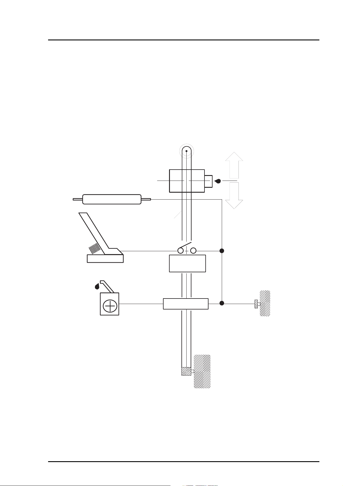
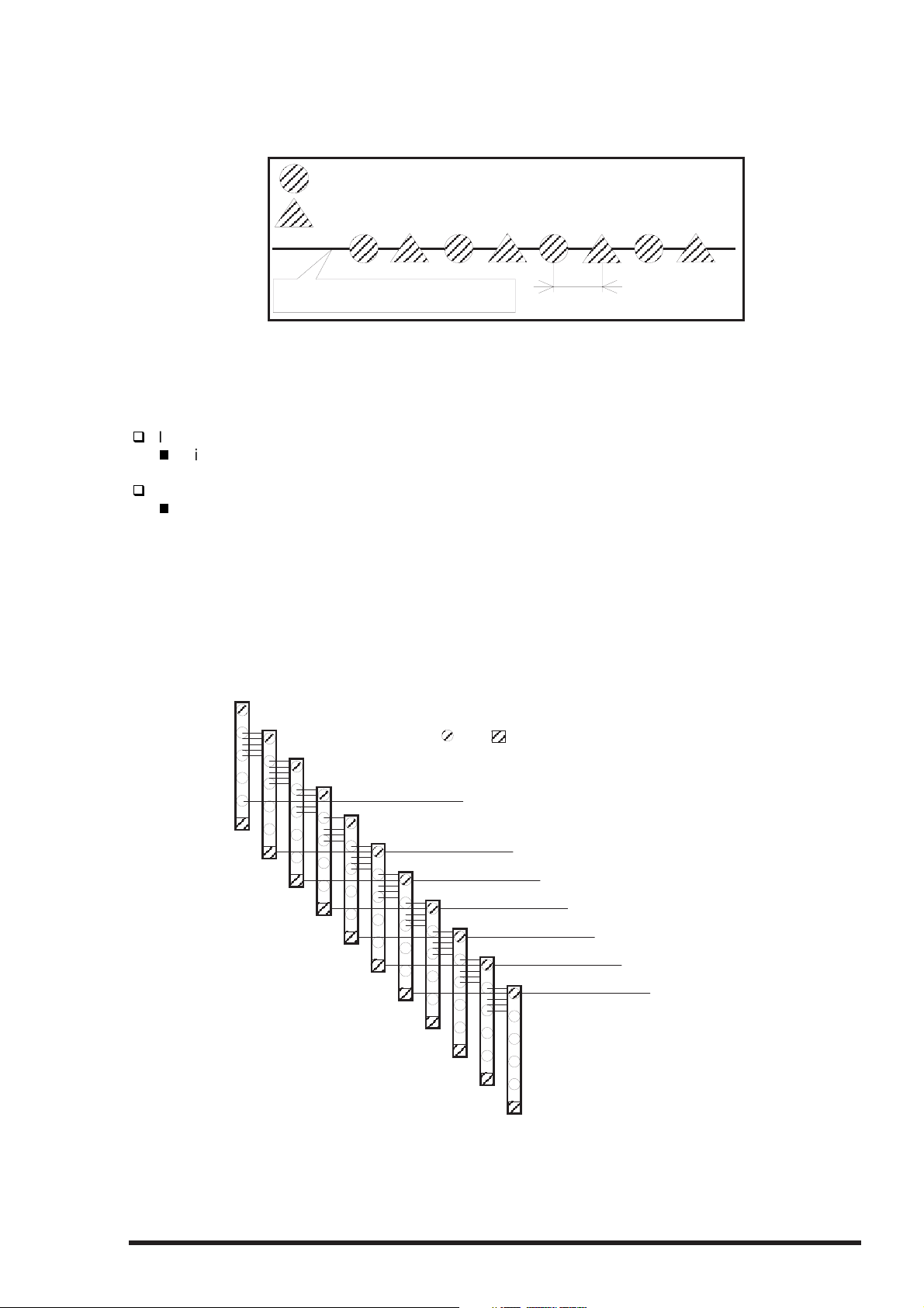
2.1.1 Printer Mechanism
Unlike previous EPSON Ink Jet printers, printer mechanism of Stylus Color 400 does not have exclusive
mechanism to change over paper feeding and Pumping operation. In stead, this control is done by the
turning direction of paper feed/pump motor and position of carriage at that time. Also, unlike previous print
heads, print head of this printer became one unit combined with black and CMY head. Black head has
64 nozzles, 180 dpi(vertical direction) and CMY head has 21 nozzles, 90 dpi (vertical direction). Also,
since these print head is driven by frequency 14.4Khz, this printer can print double resolution(1440
dpi/100-dpi) than Stylus Color. Following figure2-1 shows outline of printer mechanism.
Carriage Unit
(Prinr Head Unit)
Platen Drive Mechanism
Paper Pickup Mechanism
Pump Drive Mechanism
Timing Belt
Paper Pick Up
Trigger Lever
Pumping Position
Paper Feed Motor
Rev.A
Carriage Motor
Figure 2-1. Stylus Color 400 Printer Mechanism Block Diagram
2-1
Page 3
EPSON Stylus Color 400 Service Manual
2
As major printer mechanisms in the figure 2-1, there are four major mechanisms as they are listed below.
1) Printing mechanism 2) Carriage unit 3) Paper pick up mechanism4) Pump drive mechanism
2.1.1.1 Printing Mechanism
Basic principles of the print head which plays major role of printing mechanism is the same as previous
models; on demand type MACH head method, but there is some difference in the resolution. (Refer to
figure1-1) Also, unlike Stylus Color IIs, 820, 200 automatic correction type, in order to fix the dispersion of
mufti layer piezo electric element which is used for driving each nozzles, it is necessary to input the VH
value written on the side of print head by using exclusive program when you replace print head, control
board, or the printer mechanism.(However, there are no resistor array to decide the VH voltage on the
main control board.) Following explains print head.
PZT
PZT is an abbreviation of Piezo Electric Element. Print signal from C206 board is sent through the
driver board on the print head unit and to the PZT . Then, the PZT pushes the top cavity which has
ink stored, and make the ink discharge from each nozzle located on the nozzle plate.
Cavity Set
Ink which is absorbed from ink cartridge go through the filter and will be stored temporarily in this
tank, which is called “cavity” until PZT is driven.
Nozzle Plate
The board with nozzle holes on the printer head surface is called Nozzle Plate.
Filter
When the ink cartridge is installed, if any dirt or dust around the cartridge needles are
absorbed into the head inside, there is a great possibility of causing nozzle clog and
disturbance of ink flow and finally causing alignment failure and dot-missing. In order to
prevent this, filter is set at cartridge needle below and ink is once filtered here.
Printhead driver board
Ink Cartridge Sensor
Actuator
Cartridge needle
(Ink Cartridge)
PZT
Ink Supply Tube
Cavity set
Nozzle Plate
Figure 2-2. Print Head Sectional Drawing
2-
Filter
Rev.A
Page 4
Chapter2 Operating Principles
3
2.1.1.1.1 Printing Process
Following figures indicate the sectional drawing of normal state and ejecting state of the print head.
(1) Normal State:
When the print signal is not output, PTZ also does not move in the waiting state(normal state).
PZT
Cavity
Ink Course
Nozzle
Figure 2-3. Print Head Normal State
(2) Ejecting State:
When the print signal is output from the C206 main board, IC(IR2C72C:Nozzle Selector) located
on the Print head unit latches the data once by 1-byte unit. Appropriate PZT latched by nozzle
selector is pushed into the cavity by applying common voltage from the C206 main board.
By this operation, ink that is stored in the cavity pops out from nozzles.
Nozzle Plate
Figure 2-4. Print Head Ejecting State
Rev.A
2-
Page 5
EPSON Stylus Color 400 Service Manual
4
2.1.1.1.2 Printing Method
This section explains printing method of actual printing such as printing text at various resolution
select/printing mode and graphics printing. In order to prevent white or color banding which are peculiar
problem of ink-jet, new Micro-Weave functions are added to the previous Micro-Weave function.
The number of nozzles and printing mode according to the selected resolution are used separately by a
user. The table below shows relation between selected resolution and printing mode.
1) Full Overlap Micro-Weave
2) Part Line Overlap Micro-Weave
3) Micro-Weave: (same as previous control)
Table 2-1. Resolution and Printing mode
Vertical
direction
[dpi]
Printing
mode
Paper feed
pitch
[inch]
Forward
Overlap-
Nozzle
Non
Overlap-
Nozzle
Backward
Overlap-
Nozzle
Not used
Nozzle
360 FOL M/W 15/360
M/W 31/360 ---
720 FOL M/W 15/720
POL M/W 29/720
Note1:
M/W means Micro-Weave.
Note2:
Note3: POL means Part line Overlap Micro- Weave.
Note4:
Following explains operation outlines of new Micro-Weave functions listed above.
[1. Full Overlap Micro-Weave]
In order to print one line at horizontal direction, this printing method is designed to complete a printing
pattern by two-pass carriage operation with two different types of dot. When this two different types of dot
pass one same line twice, it does not print the same dot twice.
FOL means Full Overlap Micro-Weave.
Forward Overlap-Nozzle and backward Overlap -Nozzle are described in the [1.Full Overlap
Mirco-Weave] and [2.Part line Overlap Micro-Weave] below.
The nozzles whose configuration completely match to the black and CMY nozzle are used.
(Usually Micro-Weave type)
Therefore, all nozzles in case of CMY nozzle and #1∼#63 nozzles in the B2 line in case of
black head are its objects. (B1 line is not used at Micro-Weave. Refer to figure1-1 for detail of
nozzle configuration.)
Out of these 4 color nozzle objects, the number of all nozzles which are going to be used are
divided equally into 2 groups.
Paper feeding will be done as many as each number of nozzles which are divided into two
groups and the same number of dots.(for example, if there are two 10-nozzle groups during
360-dpi printing at longitudinal direction, paper feeding of 10/360-inch becomes available.)
At this time, two groups perform Micro-Weave individually and particular lines are passed by
two different nozzles.
#16∼#30
#16∼#30
#30∼#32 #4∼#29 #1∼#3
---
#1∼#31
---
#1∼#15 #31∼#32
--- #32
#1∼#15 #31∼#32
---
Note1)
2-
These nozzles which are divided into two groups must be set and divided in order to
be a pair of odd and even number.
Rev.A
Page 6
Chapter2 Operating Principles
5
Note2)
Two groups which are divided according to each elements will be divided either even dot or
odd dot when particular lines(level direction line) are formed and eventually, these lines will be
completed at selected resolution. Following is a conceptual figure when full overlap microweave orms a particular line.
Nozzle No.#9
Condition: 360-dpi printing
Nozzle: Total 10 nozzle/each color
Nozzle No.#4
Particular line(Completed line)
Figure 2-5. Full Overlap Micro-Weave
Note 3)
If the line which is about to be printed is even line:
If the line which is about to be printed is odd line:
[2.Part Line Overlap Micro-Weave]
This printing method is to perform Micro-Weave printing, overlapping a part of nozzles which are
used for printing. As a result, a part of raster which is overlapped consists of different browse with
different nozzles. The figure below shows 1-line Overlap at 5-dot sending as an example with
explanation on the next page.
The way firmware decides which nozzle becomes even dot or odd dot is determined
as it is described below.
First dot prints odd dot lines and 2nd dot prints even dot lines.
1st dot prints even dot lines and 2nd dot prints odd dot lines. Eventually, horizontal resolution
will be the same resolution as selected one.
360-dpi
Pass1
#1
#2
#3
#4
#5
#6
2
Note1: The paper feed pitch is 5/360-dpi in this figure.
Note2: Mark of and mean overlap nozzle.
3
4
5
6
Raster 1
Raster 10
7
8
9
10
11
Figure 2-6. Part line Overlap Micro-Weave
Rev.A
2-
Page 7

EPSON Stylus Color 400 Service Manual
6
The difference between Full-Overlap Micro-Weave and Part line Overlap Micro-Weave are following;
Full-Overlap Micro-Weave:
Printing is performed, judging if nozzles are even or odd dot by 2 different dots with all
different rasters.
Part line Overlap Micro-Weave:
After particular nozzles(only#1, and #6 in the figure2-7) are determined as overlap nozzles,
even or odd dot will be determined like Full-overlap Micro-Weave does.
(Forward Overlap Nozzle is determined as even and backward nozzle is odd.)
Also, nozzles other than particular nozzles can print at even and odd dot just by one
nozzle.
1) Overlap Nozzle : Head drive frequency is driven half of the ordinal one like 2)
below.
2) Nozzle other than Overlap nozzle : Head drive frequency is twice as much as overlap nozzle.
Usually, the firmware changes over automatically these full overlap Micro-Weave, Part line Overlap
Micro-Weave, and ordinal Micro-weave according to the selection of resolution. Also, when these three
printing modes are performed by the Stylus Color 400, the printer performs top and bottom margin
process in order to control the overprinting volume as little as possible.
2-
Rev.A
Page 8

Chapter2 Operating Principles
7
2.1.1.2 Carriage Mechanism
Carriage mechanism is to drive the carriage with print head mounted from left to right or vice versa.
The carriage drive motor in this printer is a 4-phase, 200-pole, stepping motor and is driven by
1-2phase, 2-2phase and W1-2phase drive method. This stepping motor allows the carriage to
move freely to the particular positions which is necessary for various operation, such as paper feeding,
ink absorbing, flashing, ink exchange and cleaning operations. The tables below shows carriage motor
specifications and motor controls at each mode.
Table 2-2. Carriage Motor Specification
Item Description
Motor type 4-phase/200-pole Stepping motor
Drive voltage Range
Internal coi l resistance
Driving speed(frequency) range[csp(pps)]
Control method Bi-Pola Drive
Table 2-3. Motor Control at Each Mode
Mode Driving speed
[CSP]
High speed skip 340 4080 W1-2, 2-2,1-2phase drive*
Printing(Normal) 200 2400 W1-2phase drive
Printing(SLQ) 100 1200 W1-2phase drive
Capping 80 960 W1-2phase drive
Wiping 40 480 W1-2phase drive
Cap(valve release) 20 240 W1-2phase drive
Withdrawal of cap 5 60 W1-2phase drive
42VDC ± 5%
7.8 Ohms ± 10%(per phase under 25 °C
environment)
5(60)∼340(4080)
Drive frequency
[PPS]
Drive method
*Note 1):
Acceleration 1 mode → Acceleration 2 mode → Deceleration 1 mode → Deceleration 2 mode
The reason why plural drive methods exist is that following some sequences described below
exist in the each mode and stable carriage operation and printing are performed individually
by different drive methods. This drive method is especially necessary for high speed skip.
A
/A
C206 MAIN Board
Rotor
Connecter CN6
B
/B
Figure 2-7. CR(PF) Motor Internal Block Diagram
Rev.A
2-
Page 9
EPSON Stylus Color 400 Service Manual
8
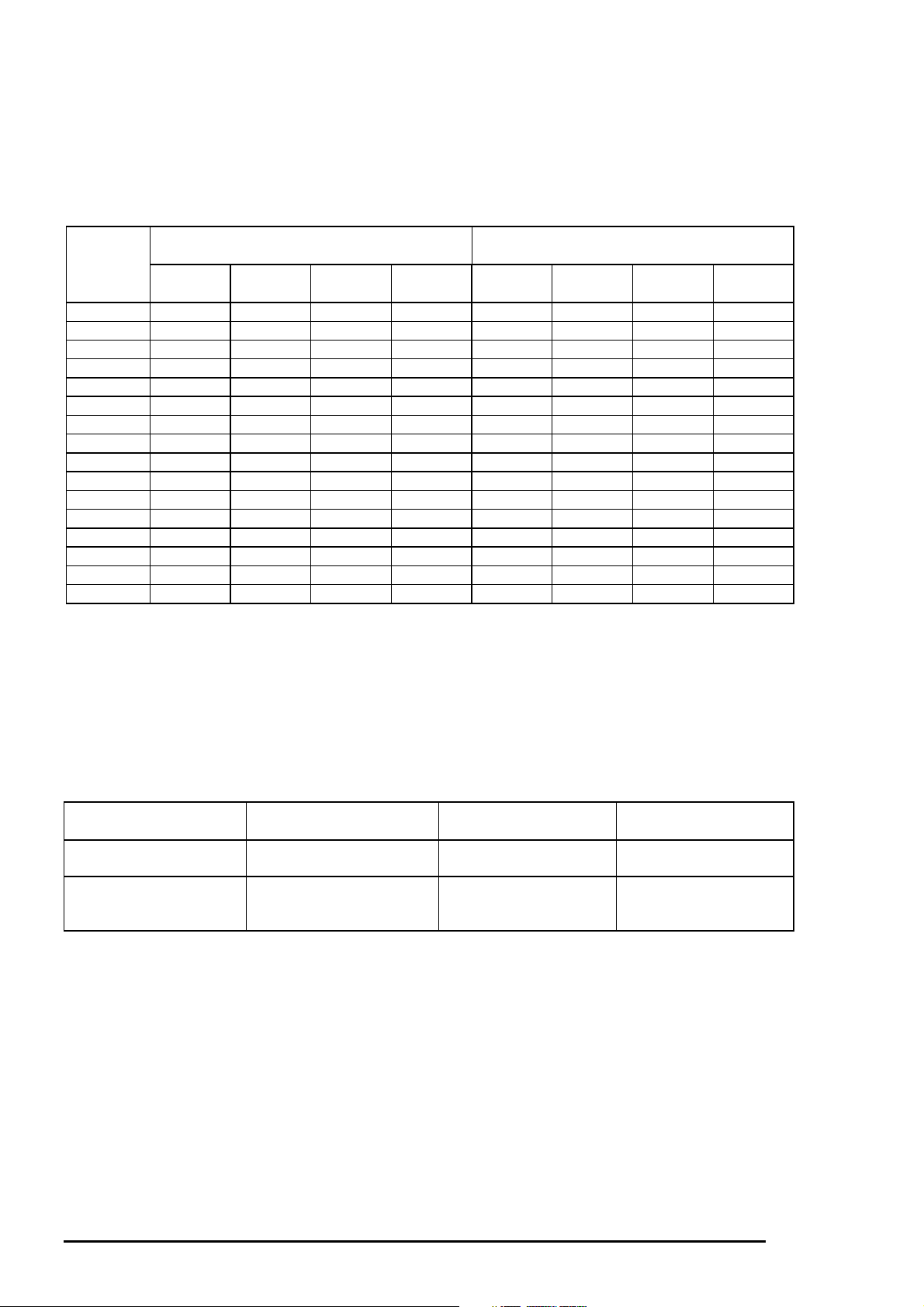
The table below shows W1-2 phase drive sequence at each steps when the rotor of carriage motor
makes one rotation. In the Stylus Color 400, in addition to a function that printing is performed with W1-2
drive phase, high speed skip mode which is a function to skip over the blank from the end of the printing
data to the next data starting point with high seed can be also performed by 2-2 and 1-2 phase drive.
W1-2 phase requires 4 times as much steps as 2-2 phase drive, calculating 2-2 phase as standard.
By using this method, it becomes possible to supply constant stable torque to the motor. As a result, it
also became difficult to be influenced by vibration from the printer mechanism during printing.
Table 2-4. Motor Drive Sequence(W1-2 phase drive)
Sequence
Number
Phase a 10a l1a Current
0010+2/3010+2/3
1001+1/3000+1
2X110000+1
3101-1/3000+1
4110-2/3010+2/3
5100-1X01+1/3
6100-11110
7100-1101-1/3
8110-2/3110-2/3
9101-1/3100-1
10X110100-1
11001+1/3100-1
12010+2/3110-2/3
13000+1101-1/3
14000+1X110
15000+1001+2/3
Phase A Phase B
Phase b 10b l1b Current
Duty
Duty
This W1-2 phase drive (or 2W1-2 phase drive) is called Micro-step and is attached with so called
2/3 • Vref or 1/3 • Vref factor, compared with drive current value (Vref100%) which is supplied at 2-2phase
drive. This Micro-Step allows the rotor to have delicate rotation. In the 2-2 phase drive method, it is usually
required to take 4-step sequence in order to rotate the rotor once. However, in case of W1-2 phase, it is
required to take 16-step sequence(in the table 2-4, sequence 0∼15) which is 4 times more than 2-2 phase
method to do that. Also, in case of 2W1-2 phase drive which can be seen in the Stylus Color etc., it takes
2-step to rotate the rotor once. The table below shows relation of rotation direction of rotor and carriage
proceeding direction.
Table 2-5. Relationship Between Rotor Direction and Carriage Operation
Carriage proceeding
direction
HP→80 column direction
80 column→HP direction
Rotation direction of
Rotor
Looking from rotor output
side, clockwise direction
Looking from rotor output
side, counterclockwise
direction
Drive method Proceeding order of
sequence
2-2, 1-2, W1-2 phase
2-2, 1-2, W1-2 phase
Sequence No.0→15
Sequence No.15→0
2-
Rev.A
Page 10
Chapter2 Operating Principles
9
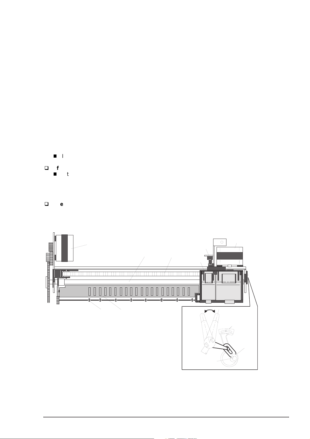
The figure below shows the carriage mechanism. The print head as a core of the printing mechanism is
stored in the carriage unit. This print head keeps the tilt of print head in flexible and adjustable structure by
moving the adjustment lever up and down by the tilt adjustment mechanism. (Refer to chapter 4 for more
details) Also, parallelism adjustment lever is mounted on the left and right side of carriage guide shaft and
it adjusts parallelism degree between platen and shaft when this shaft is installed to the printer
mechanism.
After this adjustment is completed and operate PG adjustment lever, it becomes possible to change the
space between the platen surface and the print head surface into 2 phases; either 1.1mm to 1.8mm. It is
possible to vary the space between platen surface and print head by rotating the axis of carriage guide
shaft which itself is decentralized, with the operation of PG lever. This is the mechanism that user can
adjust the appropriate PG value by himself according to the paper thickness or any other environmental
conditions such as paper curl.
Carriage lock mechanism is to prevent the carriage from being left at uncap position for a long time
because of vibration during the printer transport or mishandling by the users. If the carriage is left at uncap
position and uncap state of the print head for long time, an ink on the print head surface gradually
becomes viscosity. As a result, the nozzle will be unable to discharge an ink. To make matters worse, the
holes(crater) of nozzle may be completely clogged by the viscosity ink and it may not be able to return to
the normal condition just by cleaning operation. In order to prevent this, printer goes to carriage lock state
at the following conditions.
After Power OFF operation:
If the power is turned off on the way of printing or any other performance, carriage lock will be
performed in the end after completing initialize operation.
After power ON operation:
After power is turned on and automatic P-On Cleaning is performed, then carriage lock will be
performed. P-On Cleaning is an automatic head cleaning that is performed when the power is
turned on. The timer IC always calculates printer’s power OFF time by the power of lithium battery
mounted on the C206 main board. P-on cleaning function automatically selects the cleaning level
according to the time which the printer is not in used.
After Eject the paper:
After Load/Eject button is pressed and the paper is ejected, if the data is not input, the printer
performs carriage lock and goes to standby state. However, if the paper is loaded to the printer
inside by Load/Eject button, the printer does not perform carriage lock operation.
Paper Feed Motor
Eject Roller
Paper guide(Front)
Carriage home position Sensor
PF Roller
Timing Belt
Carriage Unit
Front Side
Figure 2-8. Carriage Mechanism Top (Viewing)
Carriage Motor
Rear Side
Parallelism
Adjust Lever
Fixing Bush
Carriage
Guide Shaft
Rev.A
2-
Page 11

EPSON Stylus Color 400 Service Manual
0
2.1.1.2.1 Paper Gap Adjust Mechanism
This mechanism can be set by the users and can prevent various problems related to low image density
or print with any dirt by changing the positions of PG lever according to the paper types.
Table 2-6. Platen Gap Adjust Lever Setting
Paper Lever position PG adjustment value
Normal paper,
Coated paper
Envelopes Rear 0.9mm
It is a major premise that parallel adjustment is done correctly for the space between head and platen
(PG adjustment value above) which can be changed by platen gap adjustment.
Parallel adjustment should be done when the serviceman mounts the carriage guide shaft on the printer
mechanism during the production process or repair service. In the adjustment, the space between
parallel adjustment lever and gage should be 1.04 mm.
Front 0 mm
(1.1mm between head and platen)
(2.0mm between head and platen)
2-1
Rev.A
Page 12

Chapter2 Operating Principles
2.1.1.3 Paper Feed Mechanism and Pump Mechanism
Mechanisms that send the paper in the hopper to inside the printer and perform constant paper
feed in order to perform printing on the sent paper are called paper feed mechanism as generic name.
In the Stylus Color 400, 4-phase, 200-pole hybrid type pulse motor is used in the PF motor as a motive
power of the paper mechanism and driving is done at 2-2 and 1-2 phase drive method. This motor is
not only used as a power source for paper feed mechanism but also used as power source of pump
mechanism which is necessary for print head cleaning. By using this pulse motor, it becomes possible
to use high speed driver or intermittent drive for the various paper feeds and pump operations such as
paper feed, slight paper feed, high and low speed absorption of pump operations. Following tables(Table
2-7 and 2-8) show PF motor specifications and control method at each mode.
Table 2-7. PF Motor Specification
Item Description
Motor type 4-phase/200-pole Stepping motor
Drive voltage
Coil Resistance
Drive frequency [csp(pps)] 400-4320Hz
Control method Bi-Pola Drive
Table 2-8. Motor Control Method at Each Mode
Mode Drive Method Drive Frequency
Paper feed A 2-2 phase 4320 231
Slight paper feed 1-2 phase 400 2500
Slight paper feed 1-2 phase 2400 417
High speed attraction of pump 2-2 phase 4100 243
Low speed attraction of pump 1-2 phase 1800 555
Low speed paper feed 1-2 phase 1200 833
Paper feed B 2-2 phase 3400 294
Paper feed C 1-2 phase 4000 250
Ordinal absorption of pump 1-2 phase 4100 243
42VDC ± 5%
7.8 Ohms ± 10%(per 1 phase under
25°C environment)
Pulse Space
[Hz]
(µs)
Following tables show 1-2phase drive method at PF motor drive and each drive sequence at 2-2phase
drive method.
Table 2-9. 1-2 Phase Drive Method
Step No. Clockwise Counter clockwise
Phase A Phase B Phase A Phase B
1 +2/3 +2/3 +2/3 +2/3
0+1+10
2 -2/3 +2/3 +2/3 -2/3
-1 0 0 -1
3 -2/3 -2/3 -2/3 -2/3
0-1-10
4 +2/3 -2/3 -2/3 +2/3
+1 0 0 +1
Table 2-10. Drive Sequence at 2-2 Phase Drive
Step No. Clockwise(CW) Counter clockwise(CCW)
AB A B
1 +2/3 +2/3 +2/3 +2/3
2 -2/3 +2/3 +2/3 -2/3
3 -2/3 -2/3 -2/3 -2/3
4 +2/3 -2/3 -2/3 +2/3
Rev.A
2-11
Page 13

EPSON Stylus Color 400 Service Manual
2
Papers on the ASF (auto-sheet-feeder) supplied by the user are carried to the printer inside by paper
pick up sequence. Unlike the previous models, ASF of Stylus Color 400 has mufti feed prevention
mechanism. Following explains this function and figure below shows its mechanism.
[1. Multi feed prevention mechanism]
When the Load/Eject button is pressed, reversed rotation of PF motor is performed.
The return lever resets papers which are already in the out of stand by position in the stand by position
and make it possible to perform stable paper feeding by picking up the paper again.
Pintch Roller
D-Cut Roller
CAM
Hopper
Hopper spring
2)
1)
2)
Pad spring
Return Lever
[Standby state]
Figure 2-9. Multi Paper Feed Prevention Mechanism
Following explains process of multi feed prevention step by step. Refer to the figure above and confirm
its operation.
[Step 1]
[Step 2]
[Step 3]
[Step 4]
When the load/Eject switch is pressed or printing order is input from the PC, PF motor rotates
counterclockwise and makes the CAM rotate towards direction of 1 in the figure above.
When the CAM covers the notch by the return lever, that position is considered as home
position, being monitored by ASF sensor.
When the CAM rotates toward 1 in the figure above, the return lever is pushed by the notch
of CAM and falls towards 2. At this time, the return lever moves to direction 3 by this
motion, and push down the pad which is waiting in the below part. At this time, friction of
pinch roller and pad will be canceled.
The papers which are out of stand by position by the previous paper feed motion are
returned to the paper stand by position by flip over strength of return lever. After this,
PF motor rotates clockwise and the printer goes to pick up sequence.
[Returning state]
2-1
Rev.A
Page 14

Chapter2 Operating Principles
3
In the paper pick up mechanism of Stylus Color 400, same mechanism as Stylus Color IIs/820
are applied. This mechanism changes adjoined lines of gear by colliding trigger lever with carriage unit
and convey the motive power on the platen to the ASF side(paper roller). The figure below
shows mechanism with explanation.
[2. Paper pick up mechanism]
When the Load/Eject switch is pressed or printing order is input, the carriage unit moves until
the left edge and collides with paper pick up trigger lever. When the carriage collides with this trigger
level, a planetary gear located on the same axis is also pushed at the same time and conveys
the motive power on the platen to the adjoined gear line side for ASF drive.
Paper Pick Up
ASF Roller Drive Gear
Planetary Gear
Trigger Lever
Eject Roller Drive Gear
Eject Roller
Transmission Gear
PF Motor Pinion Gear
ASF Roller Transmission Gear
Platen Roller Drive Gear
Platen Roller Transmission Gear
Figure 2-10. Paper Pick Up Mechanism
[3. Paper feed mechanism]
After papers in the ASF receive controls from pick up and multi feed prevention mechanism, they are
sent to the printer inside. The papers picked up by paper roller in the ASF goes to between platen
and roller support. Also, the eject roller pushes out the paper completely until the end and the roller
support drops the paper in the eject tray. The eject roller is driven with an eject paper notched roller as
pair where is located on the paper eject roller. Paper eject notched roller solves the deflection of paper
that is in the between platen eject notched roller and paper eject roller and always keep a certain space
between print head and paper surface. The figure below shows the paper feed mechanism.
Paper
Eject Notched Roller
Support Roller
Eject Roller
PF Roller
Figure 2-11. Paper Feed Mechanism
Rev.A
2-1
Page 15

EPSON Stylus Color 400 Service Manual
4
2.1.1.4 Ink System
Ink system mechanism consists of 1)cap mechanism, 2)pump mechanism, 3)carriage lock
mechanism, 4)waste ink absorber and 5)ink sequence. Out of these mechanism, from 1) to 4)
are physical mechanism and parts which are mounted on the printer mechanism and 5) ink
sequence is performed automatically by firmware. Also, unlike previous models, since
Stylus Color 400 has no engage/disengage mechanism to change over pump mechanism and
paper feed mechanism, it is one of the major characteristics that pump and platen are always
at work whenever the PF motor is driven. The figure below shows head positions when the ink
system and various ink sequence are performed.
Platen Drive Gear
Eject Roller Drive Gear
Eject Roller
Trasmission Gear
Head Cleaner
Carriage Lock
PF(Pump) Motor Pinion
Pump Roller
Figure 2-12.Ink System Mechanism
2975 dot
Cap Unit
CRHP
ABCDEFGH
Figure2-13. Major Ink Sequence Position on the Carriage Mechanism
2-1
Rev.A
Page 16

Chapter2 Operating Principles
5
2.1.1.4.1 Pump Mechanism
In the Stylus Color 400, there is no switch or mechanism to change over the pump/paper feed
mechanism. Therefore, whenever the paper feed/pump motor rotate, pump drive roller in the pump unit
inside rotates. However, ink absorption/non ink absorption are separated by the roller rotational direction.
Also, even if the pump driver rotates toward ink absorption and the carriage position is in the false
absorption position, only driving in the pump mechanism is performed and actual ink attraction is not
done. The figure below shows process of conveying motive power to the pump drive roller.
Gear A
Axis of Paper Eject Roller
Gear B
Gear C
Actually, these parts
are one unit.
Compression
Spring
Pump Drive Roller
Figure 2-14. Pump Mechanism Power Transmission Process
The process of conveying the motive power to the paper eject roller by rotating the pinion of PF motor
is descried in figure 2-12. This motive power is conveyed to the Gear C through the Gear B.
In the figure above, although the lever in order to drive Gear C, carriage lock, head cleaner mechanism
is shown separately, it is c onstructed as one unit. Since the engagement of thes e two parts depends on
the tension of the compression spring, if the lever is burdened, only Gear C and pump roller rotate and no
more motive power is conveyed to the lever part.
Rev.A
2-1
Page 17

EPSON Stylus Color 400 Service Manual
6
The table below shows PF/Pump motor rotational direction and pump system operation.
Table 2-11. Relationship Between Pump Motor Rotation and Pump Operation
PF/Pump motor rotational direction Pump unit operation
Clockwise(CW)
forward rotation
Counterclockwise(CCW)
backward rotation
The figure below shows the pump operation at clockwise and counterclockwise rotation.
1)Release from the Pump pressure welding
2)Head cleaner reset
3)Carriage lock reset
1)Rotation towards pump pressure welding
2)Head cleaner set
3)Carriage lock set
CW Rotation
Tube pressured
Figure 2-15. Pump Roller Rotation and it’s Operation
In the ink absorptive operation such as cleaning, flushing and initial ink charge except for printing
operation, ink in the ink cartridge drains to the waste ink absorber(pad) through the cap by the pump unit
drive. In case of printing and flashing drive, ink is popped out by the PZT in the print head, but in case of
absorptive operation such as cleaning and initial ink charge, ink absorption is performed
only by the pump drive without PZT drive after the head surface is adhered to the cap.
The next page explains cap mechanism and relation between printer operation and cap.
CCW Rotation
Tube released
2-1
Rev.A
Page 18

Chapter2 Operating Principles
7
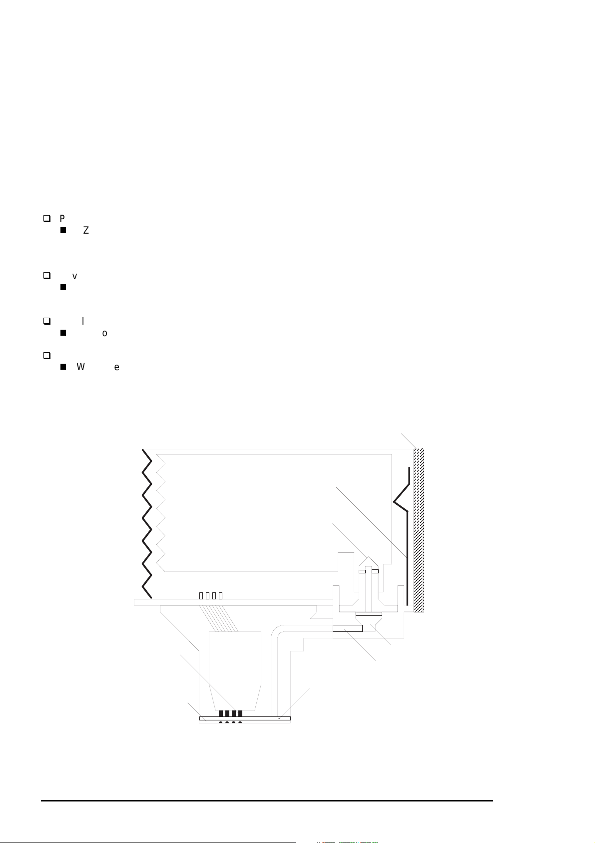
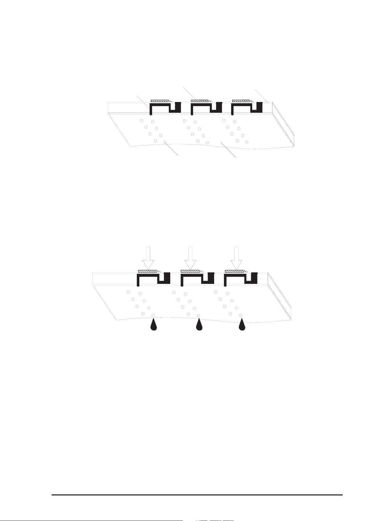
2.1.1.4.2 Cap Mechanism
In the cap mechanism, in order to prevent ink from being thickened on the head surface, it is controlled
that the head surface stays adherent to the rubber frame of the cap surface when the power is off.
The absorber is spread in the cap and can hold a certain amount of ink which is absorbed from the
head without draining it to the waste ink pad. Also, in the bottom of absorber, there are two valves in order
to control adhesion of head and cap surface, and one exit to drain ink to the waste ink pad.
A
Flag for Carriage
Ink Eject Valve
Negative pressure
release valve
Valve
Close state
B
Release state
Flag for frame
Head surface and
cap are adhered
each other.
Actual and false
absorptions.
During cleaning, initial ink
charge, and right flushing.etc.
Ink absorption in
the cap.
During left flushing and paper
feeding,etc.
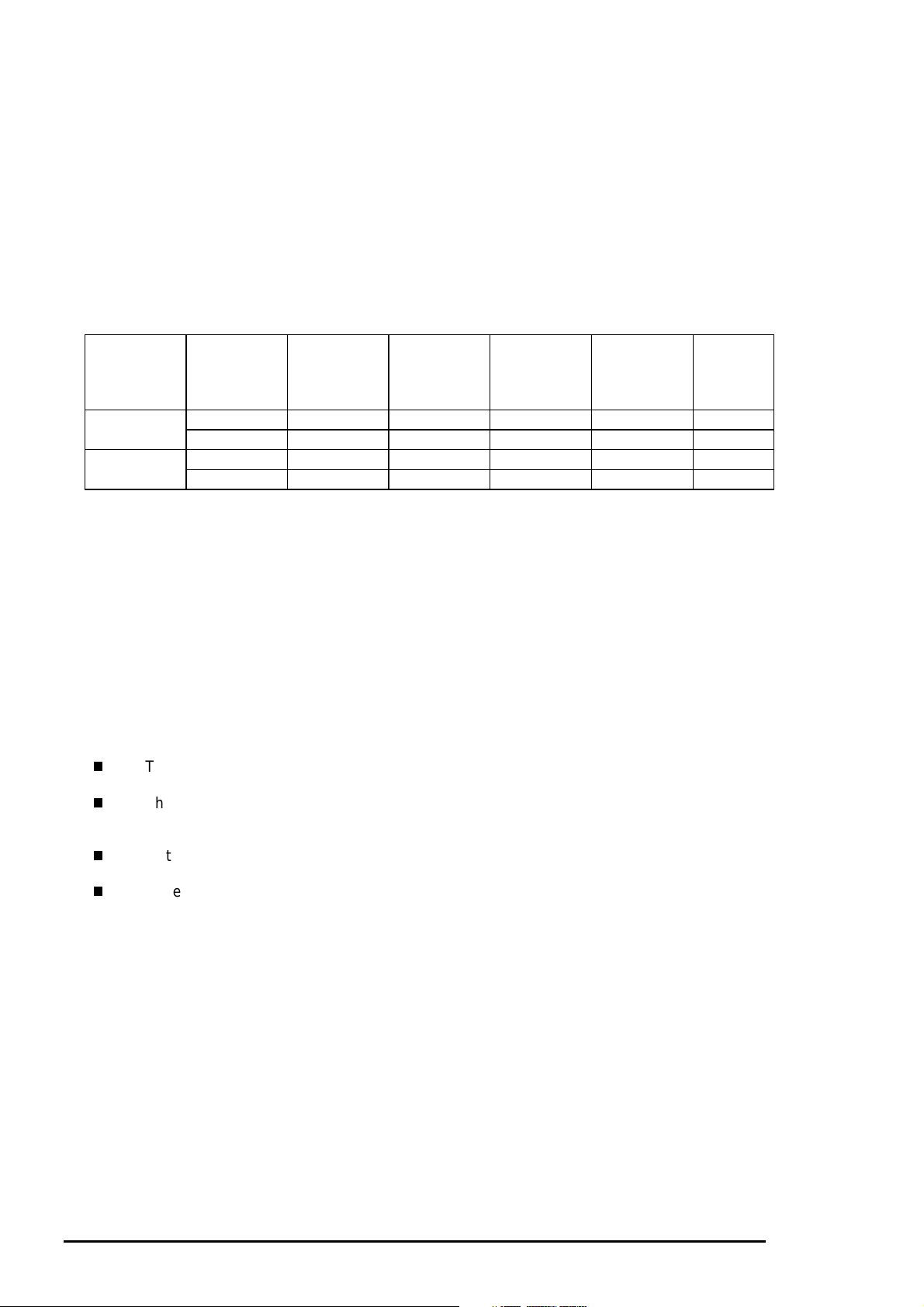
Figure 2-16. Cap Mechanism Operation Principle
If the carriage is out of HP(in this case, in the printable area or paper feed position), the valves on the
cap mechanism stays in the position A in the figure above and are always closed. In this condition,
the carriage collides with flag, actual ink absorption and slight ink absorption are performed.
Also, by moving the carriage to further right side and colliding the flag for opening the valves with
the frame, negative pressure is released in the state that head surface and cap are adhered. This
makes it possible for ink on the nozzle plate surface to be ready for leaving from the cap in the stable
condition.
Rev.A
2-1
Page 19

EPSON Stylus Color 400 Service Manual
8
2.2 Electrical Circuit Operating Principles
Stylus Color 400 contains the following four electric circuit boards.
C206 PSB/PSE board
C206 Main board
Head Driver board
C206 PNL board
C206 PSB/PSE, C206 board are explained in this section. The head drive board is installed in the head
unit on the carriage. The figure below shows major connection of the 3 boards and their roles.
AC100V
RCC Switching Regulator
(C206 PSB/PSE Board)
CR Motor
PF MOTOR
(Pump Motor)
+5 V DC
+42 V DC
C206 Main Control Board
(C206 Main Board)
+5 V DC
+42 V DC
PE Sensor
BCO/CCO Sensor
INK END Sensor
(Firm Wear)
ASF Lever
Position Sensor
2-1
Thermistor
Print Head
Head Drive Board
Figure 2-17. Electric Circuit of Stylus Color 400
Rev.A
Page 20

Chapter2 Operating Principles
9
2.2.1 C206 PSB/PSE Power Supply Board
C206 PSB/PSE board is a power supply board with a RCC switching regulator, which generates +42VDC
for drive part and +5VDC for logic part to drive the printer. One of the major characteristic of this board is
that the same secondary switch is used as Stylus Color series printer. By using this switch, the following
difference can be seen as superficial phenomena compared with products applied with primary switch
method, such as Stylus Color IIs, II and Stylus 800/1000 series printer. The table 2-12 below shows
application of voltages generated by C206 PSB/PSE board.
1) Even if the switch is turned off during the middle of printer operation, since the driving
power is turned off after the carriage goes back to the carriage lock position,
the possibility of clogging ink nozzle will be decreased.
2) If the switch is turned off when the papers in the printer are still being carried except for
the papers in the hopper, the same operation mentioned above is performed and the
driving power is turned off after the paper is completely ejected.
Table 2-12. Application of DC Voltage
Voltages Application
+42VDC
+5VDC
CR Motor
PF/Pump Motor
Head driving power supply
Power supply for logic control
System control signal
Sensor circuit power supply voltage
LED panel drive power supply
Nozzle selector control signal power supply voltage
Figure 2-18 shows block diagram of C206 PSB/PSE board. The process from the input of AC100V to the
output of 42 V DC and 5 V is explained below.
1) Regardless of the state of power switch(On or OFF), the voltage is always applied in the primary
side of the power supply board from the moment or at the state that AC-plug is plugged in.
At this time, F1 plays a role of preventing AC100V from coming into the F1.
L1 and R1-R2 also prevent high harmonic wave noise generated in the RC circuit filter which consist
of C1∼C4 and R1∼R2 from going out, and eliminate the noise from outside here.
2
2) The AC is full-wave rectified by diode bridge DB1, and converted to
electrolytic capacitor C11.
3) The pressured up direct current makes Q1 On through the starting resistor R31 and starts the primary
side of the circuit.
4) When the primary side is On state, the energy(current) led by the electromagnetic induction through
the trans (T1) does not flow to the secondary side since the diode(D51) on the secondary side
is installed in the opposite direction.
5) When the energy which is charged in the trans is reaching the saturated state, the voltage which
makes the Q1 On becomes weak gradually. At the point that this voltage drops at the
certain voltage, C13 absorbs the current in the opposite direction and Q1 is quickly shut off by
the resulting sharp drop.
6) When the primary side is turned off, the energy charged in the T1 is opened according to the
diode(D51) direction which is installed on the secondary side. Basically, 42 V DC is output
by these circuit operations and the number of T1 spiral coil .
x AC in voltage by smoothing
7) +5VDC is generated by pressured down this +42VDC as power supply. IC51 pressures down the
+42VDC and generates precise +5VDC by chopping off the output, forming the standard santooth
wave form by the outer RC integration circuit.
Rev.A
2-1
Page 21

EPSON Stylus Color 400 Service Manual
0
DB1 C11
Full Wave
Rectifier circuit
L1,R1-R2 C1-C4
Filter Circuit
F1
Prevention of
current flow
Q1
Q2,Q3,
Smoothing
circuit
Main switching
circuit
Q31,PC1
Feedback
circuit
T1
D51
T
R
A
N
S
PC1
Photo coupler
C51
Smoothing
circuit
C84,Q84
Power OFF
Delay circuit
ZD81-86,
ZD51
+42V constant
voltage control
circuit
+42V overvoltage
protection circuit
ZD52,87
+5V generation
(IC51)
circuit
ZD53
+5V overvoltage
protection circuit
+42VDC
+5VDC
PSO Signal
AC100V
Figure 2-18. C206 PSB/PSE Board Block Diagram
The C206 PSB/PSE board has various control circuits to stop output if malfunction on the power supply
board, on the main board or on the duty of printer mechanism happen. Following explains each control
and protection circuits.
1) +42V Line Constant Voltage Control Circuit:
The output level of the +42V line is monitored by a detection circuit consisting of seven Zener diodes.
This circuit prevents voltage from dropping for constant output voltage.
2) +5V Line Over voltage Protection Circuit:
This protection circuit is in the same line as +42V over voltage protection circuit is located. The output
voltage level of the +5V line is monitored by a Zener diode. This circuit shuts down the circuit
operation forcefully when the voltage level exceeds +9V.
3) +42VDC Line Over voltage Circuit:
This circuit is in the same line as +5V line over voltage protection circuit is located. The output level is
monitored by two Zener diodes. If the voltage level exceeds +48VDC, this circuit stops circuit
operation forcefully.
4) +5V Line Constant Voltage/Constant Current Control Circuit:
The output current is monitored by a +5VDC generation switching control IC(IC51), which also
monitors the output voltage. This information is input to the internal comparator and stabilizes +5V
line. Also, operation of the secondary side switch is explained below.
1) When the power is turned on, Q1 repeats ON/OFF automatically along with the increase and
decrease of energy on the trans coil at the primary side. While the power is being on, PSC
signal is input to the power supply board from the C206 main board.
2) This signal turns Q84 on and it becomes possible to discharge energy between 8-9 of T1.
At this time, even if the power is turned off, the electrolytic capacitor keeps Q84 on for a while.
By this electrolytic capacitor, output is hold at least 30 seconds even after the power is turned off.
This time helps the printer to complete the P-Off operation.
2-2
Rev.A
Page 22

Chapter2 Operating Principles
2.2.2 C206 MAIN Board
Various DC voltage generated on the C206 PSB/PSE board is added various signals in order to drive the
printer function on the C206 main board, and the drive of CR/PF(Pump) motor and printing head is
performed. This control board consists of system part and drive part. In the system part, there are
formation and controls of various signals in order to drive the CR/PF(pump) motor, sequence control
by input from the sensor circuit, and also output of signal to select appropriate nozzle for the printing
head. On the other hand, the drive part has constant current drive by the driver IC for the CR/PF(pump)
motor drive and trapezoidal wave form circuit for head drive.
C206 Main Board
PROM4M
(IC3:EPROM)
M5M411664
(IC4:D-RAM)
System
DRAM Control
Head Temperature
From A
From B
From B
TPM 95C061
(IC1:CPU)
SN75LBC775
(IC16 Transceiver)
H8D2813D
(IC6)
LB1845
(IC14)
LB1845
(IC15)
Timer (IC5)
E05B44
(IC2: Gate Array)
EEPROM (IC11)
Print Head
Carriage Motor
PF(Pump) Motor
CR/PF Motor Drive
Panel I/F
Head Common Drive
Power
to B
to A
Centornics I/F
Serial I/F
Sensor Circuit
Figure 2-19. C206 Main Control Board Block Diagram
[CPU]
The C206 main board is controlled by a 16-bit CPU(TMP95C061AF) running at 25Mhz. Gate array
manages most of controls and monitors. Likewise the Stylus Color, the D-RAM is applied for RAM
which is used as work area for receiving data and developing the data and CPU manages its control
such as CE, RAS/CAS controls.
[Gate Array]
E05B44 controls following functions.
Motor control : Each motor performs data transmission(W1-2 phase) that motives
Micro-Step.
Head voltage control: In the ink jet printers, drive voltage wave form(trapezoidal wave form)
in order to drive PZT is formed in the various shapes according to the
types of the printers.
Therefore, it is necessary to form appropriate drive form for each head.
Head voltage control forms necessary wave form for each control
signals and outputs them.
EEPROM control: The correction value to eliminate the error of each printers at the
production process is installed in the fixed address of IC.
When the power is turned off, the contents set by users is
written instantly, and is red to the RAM when the power is turned on.
Sensor Data: The sensor detects information at the various conditions, which is
necessary for the printer operation. The gate array recognizes
signals and changes over to the next control.
Rev.A
2-21
Page 23

EPSON Stylus Color 400 Service Manual
2
Timer Data: The timer IC that uses lithium battery as power source monitors how long
the power is off. When the power is turned on, it is changed to appropriate
cleaning level according to the time that the power is off.
Serial Data: The gate array receives serial data through the transceiver IC.
Parallel I/F control: With the use of IEEE1284 Nibble mode, it became possible not only to
receive the data from the host but also to return various information which
the printer possesses to the host.
[Common Driver IC]
The trapezoidal wave form circuit for head drive is became to HIC from the previous discreate structure.
Because of this, it is not necessary to adjust the adjustable VR on the board during production process.
Various electric charge/discharge control signals are all processed in the HIC.
[CR/PF Motor Drive Circuit]
Constant current drive is performed by the HIC. Out of this, only CR Motor is controlled for Micro-Step
control and HIC becomes poss ible to flow the appropriate current value at each steps. ( PF Motor has
only 1-2, 2-2phase drive method). Also, bipolar drive is performed on the 4 cables individually. Following
pages explain each major control circuit.
2-2
Rev.A
Page 24

Chapter2 Operating Principles
3
2.2.2.1 Reset Circuits
The reset circuit prevents the CPU from running away, which is caused by the unstable voltage in the
logic line during the power ON/OFF operation. Also, this circuit monitors level of power voltage at the over
loading or malfunction on the circuit and manages the printer to operate normally, keeping the damage to
the printer minimum during the abnormal situations. On the C206 main board, 2 ICs are mounted ; IC for
monitoring the voltage level (logic line) and IC for monitoring the voltage level (power line) and both
are monitored by the gate array and CPU.
The figure below shows reset circuit block diagram with explanation on the next page.
+5V
+5V
+42V
R10
R6
PST592D
(IC8)
TMP95C061
(IC1)
15
P84
10
/NMI
M51955B
(IC9)
2
IN
4
GND
Vout
NRES
Vcc
GND
P85
/RESET
1
2
3
4
16
30
NC8
VCC
OUT
NC5
C47
8
7
6
5
+5V
174
R1
R138
E05B44
(IC2)
/RESET
Figure 2-20. Reset Circuit Block Diagram
[PST592(IC8)]
The actual operation of the circuit is to keep outputting Low signal until +5V line goes up to +4.2V
when the power is on, and to cancel the reset signal with output of High signal when the voltage goes up
more than 4.2V.
[M51955(IC9)]
This IC also performs as monitor on the power line same as the reset IC for logic described above.
High/Low is judged at the 33.2V.
[Relation between IC8 and IC9]
Reset signal which is low and output by IC9 is input to the CPU and gate array and system reset operation
is performed. Also, this signal is detected on the IC9(IC for reset monitor, power line) and outputs the
same Low signal towards CPU/NMI terminal by being input to NC5.
Rev.A
2-2
Page 25

EPSON Stylus Color 400 Service Manual
4
2.2.2.2 Sensor Circuits
The following sensor circuits are mounted in the Stylus Color 400 and selects appropriate operations
based on the returned information.
ASF Sensor: An ASF sensor detects the position of return lever when the power is
(Photo) turned on, and causes the paper to be picked up by the pick up roller
from the normal initial condition. (Refer to section 2.1.1.3 for detail.)
PE Sensor: A PE sensor determines if there is paper in the printer. Based on the
(Photo) signal form this sensor, a particular paper edge treatment such as
Micro-weave printing is performed.
HP Sensor: A HP sensor detects the carriage home position.
(Photo) It is used for managing printing position and cleaning, etc.
Thermistor Sensor: A thermistor sensor keeps stable printing quality, changing PZT drive
voltage(VH) slightly according to changes of environmental
temperature.
Cartridge Sensors: Cartridge sensors are built into the Bk, CMY cartridge on the carriage
unit respectively to determine if the cartridge is installed or not when it
is exchanged or the power is turned on. In case of Stylus Color 400,
the counter is reset at every time the cartridge is removed.
The figure below shows sensor circuit. Out of the data such as EPW with IEEE 1284 Nibble mode
to be returned to the host, the data to indicate ink consumption is calculated and managed by the
counter of the firmware. Therefore, it is omitted here.
TMP95C061
(IC1)
+5V
E05B44
(IC2)
Vref
AGND
AN0
SW8
SW7
SW6
SW5
SW4
18
17
20
CCO(198)
BCO(200)
PE(202)
HP(204)
ASF(206)
3
THM
CN8
+5V
CCO
BCO
+5V
2
1
CN8
+5V
3
PEV
2
1
3
2
1
3
2
1
CN4
CN5
CN11
GND
3
PE
HPV
2
GND
HP
1
ASFV
GND
ASF
Figure 2-21. Sensor Circuit Block Diagram
2-2
Rev.A
Page 26

Chapter2 Operating Principles
5
2.2.2.3 EEPROM Control Circuits
The EEPROM of Stylus Color 400 has following contents. Gate array E05B44(IC2) controls operations of
reading data when the power is on and writing data when the power is off.
Ink consumption(Bk, CMY)
CL counter(Various cleaning operations that are previously done are memorized)
Destination information
Information of various adjustment values(Bi-D, VH voltage, etc.)
CPSI pass word
Other various setting values by the user
EEPROM is connected to the Gate array by 4 lines and performs following functions.
The figure below shows EEPROM control circuit.
CS : Chip selection signal
CK : Data synchronism clock pulse
DI : Data writing line(serial data) at power off.
DO : Data reading line(serial data) at power on.
+5V
93C46(IC11)
8
VCC
CS
CK
1
127
2
128
ECS
ECK
E05B44(IC2)
3
6
ORG
5
GND
Figure 2-22. EEPROM Circuit Block Diagram
DI
DO
126
EDO
4
125
EDI
Rev.A
2-2
Page 27

EPSON Stylus Color 400 Service Manual
6
2.2.2.4 Timer Circuit
The lithium battery is mounted on the C206 main board and calculates how long the printer is not used.
The timer IC(IC5) starts counting with oscillation motivated by the CR1 using this battery as a power
source. The figure below shows connection of the Timer circuit.
+5V
D7
D1
BAT1
CR1
8
VDD
2
XOUT
3
XIN
4
VSS
S-3510ANFJ
(IC5)
CS
/SCK
SIO
+5V
Figure 2-23. Timer Circuit Block Diagram
The followings explain about operation of this circuit.
When the printer is on, power is supplied to the Timer IC by applying +5V quickly through
the D1.
This power is also used for the power to oscillate the outer CR1. The oscillation wave form is
input to XIN terminal.
Since the oscillation wave form of CR1 is analog wave form, it is processed into the
pulse form in the Timer IC.
When the printer is turned on, the Timer IC outputs power off time as serial data to the gate
array.
Once the printer is turned off, 3VDC of BAT1(lithium battery) is supplied as power source for
he Timer IC through D7.
Since +5V at the power on is higher than +3V of the lithium battery, the power is not being
consumed from the lithium battery.
1
6
7
123
122
121
124
TCE
TIO
TCLK
TDATA
E05B44(IC2)
2.2.2.5 DRAM Control
In the Dynamic RAM control, output and formation of CAS and RAS control signals become necessary
in addition to the output of CS signal. The CPU TMP95C061AF not only controls that but also perform
the output of CS signal of P-ROM. Refresh timing is performed in the CAS Before RAS.
2-2
Rev.A
Page 28

Chapter2 Operating Principles
7
2.2.2.6 Print Head Control Circuit
The print head control circuit of Stylus Color 400 has following characteristics.
Common wave form circuit became one HIC.
Slight vibration mode is added.(when the CR motor is accelerating)
High speed drive 14.4Khz (trapezoidal wave form
Big Nozzle configuration (resolution in the vertical direction)90dpi
(However, black nozzle is 2 lines structure)
Also, Stylus Color 400 does not have Micro-dot control as dot shooting control, but there are two types;
Normal-dot and Normal dot-2dot. Normal-dot-2dot was called Dual Firing in the Stylus Color IIs/820.
These setting/change are controlled automatically by setting of the printer driver that is determined
by the user. The followings are required conditions to perform the normal-dot 2-dot.
At the OHP sheet setting (360X360 dpi)
At the ordinary paper and resolution 360X360 dpi setting
The control circuit is considered as 2 divided parts; 1) trapezoidal wave form generation circuit
(common drive circuit) to drive PZT in the head, and 2) Nozzle-selector drive circuit to determine
which nozzle should be used. The Nozzle-Selector is attached to the head unit just like the previous
models. The common drive circuit is sumed as one HIC and mounted on the C206 main board.
E05B44
(IC2)
CHG
KC1
ND1
ND2
MD1
MD2
DATA
DATA
/STB
CLK
Figure 2-24. Print Head Control Circuit Block Diagram
[Common drive circuit]
+5V
+42V
F1
VM
VCC
CHG
KC1
ND1
ND2
MD1
MD2
DATA
DATA
/STB
CLK
H8D2813D
(IC6)
CTC
DTB
GND1
GND2
19
20
21
CN8
16
17
18
The shape of trapezoidal wave form will be different according to the printing operation, slight vibrations at
the non-printing nozzle and waiting condition. However, IC6(H8D2813) generates all wave forms as drive
wave forms by resistance(electric) welding control of common voltage drive control signal that is output
from the IC2(E05B44) in the figure above.
Table 2-13. Specifications of H8D2813 Operation
Item Contents
Drive Power Voltage
42 ± 5 %
Starts supplying after 5V rises and be stabilized./ Stops
supplying before +5V drops.
Final drive element
Operation at the Reset
2SC3746(for charging), 2SA1469(for discharging)
Off on the both charging and discharging sides.
Supplies drive power source.
This common voltage trapezoidal wave form can be observed anytime after the +5V rises even if there is
printing data or not. (Q7:3-pin,Q9:3-pin and GND on the C206 main board)
Rev.A
2-2
Page 29

EPSON Stylus Color 400 Service Manual
8
[Nozzle Selector Drive Circuit]
In order to motivate the print head to carry out printing, it is necessary to transmit the printing data to the
appropriate nozzles, which becomes direct signals to drive PZT. This data transmission is performed
by the serial method, however the data output for each black and CMY head is transmitted by the parallel
method. The figure below shows data transmission circuit.
CN8
VH
COM
Gate Array
E05B43(IC2)
NCHG
CLK
SI1
SI2
LAT
THM
U101
IR2C72C
SI0(for black)
SI1(for colr)
SCLK
LAT
XCHG
COM
Color Data
Latch
VHV
VD1/2
Black Data
Latch
Black Nozzle
Color Nozzle
Figure 2-25. Nozzle Selector Circuit Block Diagram
CLK(Clock) pulse considered as source of serial communication is commonly used for both black and
CMY. The serial data transmits data as 64-Clock unit, synchronizing with this pulse. After the data
transmission of 64-Clock is completed, LAT(Latch) signal is activated and is hold temporarily in the
IR2C72C. At this time, since the number of nozzle for Color head is fewer(21-nozzle) and different from
the ones for black head, 0 is transmitted forcefully for the data for 43 nozzle (64-21=43).
2-2
Rev.A
Page 30

Chapter2 Operating Principles
9
After the data transmission by the nozzle selector(IR2C72C) is completed and a certain time passes,
trapezoidal wave form generated by the common drive circuit once sends electric current to the PZT
for the proper nozzles which are determined in the nozzle selector circuit. This motivates PZT and
ejects the ink in the cavity. The figure below shows normal dot data transmission timing in order to form
1 dot.
Figure 2-26. Timing Chart at the Generation of Normal Dot
Rev.A
2-2
Page 31

EPSON Stylus Color 400 Service Manual
0
2.2.2.7 PF (Pump) Motor Drive Circuit
IC15(LB1845) is used for driving PF(Pump) motor. In the IC, Bi-pola drive PWM current control type
is performed, making it possible to provide stable current to each phase of motor.
Also, it makes possible to change over the reference voltage as drive current settings by making
3 combinations(100%, 66% and 33%), using 4 current setting ports(input). (Refer to 2.1.1.3 for motor
and details about sequence) However, firmware does not drive Micro-step in the Stylus Color 400.
The figure below shows connection diagram of PF(Pump) motor drive circuit.
+42V
Figure 2-27. Connection Diagram of PF(Pump) Motor Drive Circuit
Unlike using Uni-Pola drive, there is no c able for GND in the m otor s ince Bi-Pola drive is perf orm ed in the
PF motor.(Refer to figure2-10 since carriage motor interior connection diagram has the same connection
as the PF motor’s phase connection. This helps to understand the reason why the direction of
current is controlled freely in each phase by the combinations of high/low control signals.
The current control is performed by output port(46∼49 pin) of E05B44(IC2), its outer resistance
circuit and driver IC(LB1845). First, firmware possesses 16 ways of current values as current table
out of combinations made by 5 resistance which are connected to the output ports(46∼49 pin) in the
gate array. On the other hand, signals which are output by combination of these resistance’s on/off
are input in the 26 and 17 pins. HIC is driven at the same standard voltage for each A and B phase.
Actual on/off control to send electricity through the motor is performed by the process that SEN1 and
SEN2 terminals (2 and 13 pin) detect the input signal from the gate array which is monitored by the
interior comparator, confirm the current that actually flew the phase as current value again and
perform the feed back to the on/off. The figure below shows relation between input signal to the
driver IC and motor control.
+42V
R4
Ra
Rb
+5V
If feeds back the current
RS
that actually flew in the
coil to the comparator.
Note:
In case of PM motor,
same reference voltage
is input to UDN2917 for
both phase A and B, but
differet reference voltage
is set individually for
phase A and B, in case of
CR motor.
E05B44(IC2)
Gate Array
R1
R2 R3
It varies load resistance
by the control signal and
changes the ratio of partial
pressure.
UDN2917(IC14,IC15)
Figure 2-28.Motor Drive
2-3
Rev.A
Page 32

Chapter2 Operating Principles
2.2.2.8 CR Motor Drive Circuit
In the CR motor, the same LB1845(IC15) as the PF motor has is used. In the IC, Bi-pola drive PWM
current control type is performed, making it possible to provide stable current to each phase of motor.
Also, it makes possible to change over the reference voltage as drive current settings by making
3 combinations(100%, 66% and 33%), using 4 current setting ports(input). (Refer to 2.1.1.3 for motor
and details about sequence) However, firmware performs Micro-step driving in the Stylus Color 400.
The figure below shows carriage motor drive circuit.
+42V
E05B44(IC2)
MTBV0-MTBV4
MTAV0-MTAV4
CRA0
CRA1
CRB0
CRB1
CRAPH
CRBPH
75
76
72
73
77
74
Current decision
resistor
LB1845(IC15)
22
IO1
23
I11
21
IO2
20
I12
25
PH1
18
PH2
Vref1
Vref2
SENS1
E1
SENS2
E2
OUT1A
OUT1B
OUT2A
OUT2B
7
6
9
8
CRA
CR/A
CRB
CR/B
Figure 2-29. Connection Diagram CR Motor Drive Circuit
Unlike using Uni-Pola drive, there is no cable for GND in the motor since Bi-Pola drive is performed in the
CR motor.(Refer to figure2-10 since carriage motor interior connection diagram has the same connection
as the PF motor’s phase connection. This helps to understand the reason why the direction of
current is controlled freely in each phase by the combinations of high/low control signals.
The current control is performed by output port(46∼49 pin) of E05B44(IC2), its outer resistance
circuit and driver IC(LB1845). First, 10 resistance which are connected to the output port(60∼61pin,
63∼70pin) of the gate array divide each current values of phase A and B in the CR motor.
The firmware possesses 16 different ways of current values individually as current table out of
combinations made by 5 resistance which are connected to the output ports(46∼49 pin) in the gate array.
On the other hand, signals which are output by combination of these resistance’s on/off are input
independently in the 26 and 17 pins. HIC is driven at the different standard voltage for each phase A and
B.
Actual on/off control to send electricity through the motor is performed by the process that SEN1 and
SEN2 terminals (2 and 13 pin) detect the input signal from the gate array which is monitored by the
interior comparator, confirm the current that actually flew the phase as current value again and
perform the feed back to the on/off. (Refer to figure 3-31 since it is same as the one of PF motor)
Rev.A
2-31
 Loading...