

Page 1

Chapter 1
Product Descriptions
1.1 Features.................................................................................................................1-1
1.2 Specifications.......................................................................................................1-2
1.2.1 Printing Specification............................................................................................................. 1-2
1.2.2 Paper Specification ................................................................................................................ 1-4
1.2.2.1 Cut Sheet...................................................................................................................1-4
1.2.2.2 Transparency, Glossy Paper.....................................................................................1-4
1.2.2.3 Envelope....................................................................................................................1-4
1.2.2.4 Index Card................................................................................................................. 1-4
1.2.3 Adjust Lever Settings (PG adjust lever)............................................................................... 1-5
1.2.4 Printing Area...........................................................................................................................1-5
1.2.5 Environmental Condition....................................................................................................... 1-8
1.2.6 Ink Cartridge Specifications.................................................................................................. 1-9
1.2.7 Physical Specification.......................................................................................................... 1-11
1.2.8 Input Data Buffer .................................................................................................................. 1-11
1.2.9 Electric Specification ........................................................................................................... 1-12
1.2.10 Reliability............................................................................................................................. 1-12
1.2.11 Safety Approvals................................................................................................................. 1-12
1.2.12 Acoustic Noise.................................................................................................................... 1-13
1.2.13 CE Marking.......................................................................................................................... 1-13
1.2.14 Printer Language and Emulation...................................................................................... 1-13
1.3 Interface...............................................................................................................1-15
1.3.1 Parallel Interface (Forward Channel).................................................................................. 1-15
1.3.2 Parallel Interface (Reverse Channel) .................................................................................. 1-16
1.3.3 Prevention Hosts from Data Transfer time-out..................................................................1-18
1.4 Control Panel ......................................................................................................1-19
1.4.1 Indicators............................................................................................................................... 1-19
1.4.2 Panel Functions.................................................................................................................... 1-20
1.4.3 Printer Condition and Panel Status.................................................................................... 1-22
1.5 Error Status.........................................................................................................1-23
1.5.1 Ink Out ................................................................................................................................... 1-23
1.5.2 Paper Out............................................................................................................................... 1-23
1.5.3 Paper Jam.............................................................................................................................. 1-23
1.5.4 No Ink-Cartridge ...................................................................................................................1-24
1.5.5 Maintenance Request........................................................................................................... 1-24
1.5.6 Fatal Errors............................................................................................................................ 1-24
1.6 Printer Initialization ............................................................................................1-25
1.7 Initialization Settings..........................................................................................1-25
1.8 Main Components...............................................................................................1-26
1.8.1 Printer Mechanism ............................................................................................................... 1-26
1.8.2 C206 Main Control Board..................................................................................................... 1-26
1.8.3 C206 PSB/PSE Power Supply Board .................................................................................. 1-27
1.8.4 C206PNL(Panel) Board ........................................................................................................ 1-27
Page 2

EPSON Stylus Color 400 Service Manual
1.1 Features
Stylus Color 400 is designed for PC users at home and low price for that high performance.
Also, this printer has the same high color print quality(720X720dpi) as Stylus ProXL. The major printer
features are;
High color print quality
720(H) x 720(V) dpi printing
4 color printing (YMCBk)
Traditional and New Microwave
Black 64 nozzles, CMY 21 nozzles (Black=180dpi, CMY=90dpi)
During 360 dpi printing, 1 dot is fired by 2 shots and 1 dot is fired by 1 shot during 720 dpi
printing.
Built-in auto sheet feeder
Holds 100 cut-sheets (55g/m
Holds 10 envelopes
Holds 10 transparency films
Holds 65 special papers
High-speed print
200cps
By using head drive frequency 14.4KHz, printing speed is twice faster
than Stylus Color.
Compact size
Non-operating : 429mm(W) x 234mm(D) x 162mm(H)
Operating : 429mm(W) x 695mm(D) x 309mm(H)
Weight : 5.2Kg(without cartridge)
Acoustic noise
Approximately 45 dB
Bi-directional parallel I/F(IEEE-1284 level 1 device)
One unit combined black and CMY head
Windows exclusive
2
)
The following table shows consumable and option.
Table 1-1. Consumable
Item Code Remark
Black Ink Cartridge S020093 Color: Black
Color Ink Cartridge S020089 Color: Cyan/Magenta/Yellow
EPSON 360 dpi Ink Jet Paper S041025 Size: A4(200 sheets)
EPSON 360 dpi Ink Jet Paper S041059 Size: A4(100 sheets)
EPSON 360 dpi Ink Jet Paper S041060 Size: Letter(100 sheets)
Photo Quality Ink Jet Paper S041026 Size: A4(200 sheets)
Photo Quality Ink Jet Paper S041061 Size: A4(100 sheets)
Photo Quality Ink Jet Paper S041062 Size: Letter
Photo Quality Ink Jet Paper S041067 Size: Legal
Photo Quality Glossy Paper(New Release) S041126 Size: A4
Photo Quality Glossy Paper(New Release) S041124 Size: Letter
Photo Quality Glossy Film S041071 Size: A4
Photo Quality Glossy Film S041124 Size: Letter
Photo Quality Glossy Film S041107 Size: A6
Ink Jet Transparencies S041063 Size: A4
Ink Jet Transparencies S041064 Size: Letter
Photo Quality Ink Jet Card S041054 Size: A6
Photo Quality Ink Jet Card S041121 Size: 5 x 8 inches
Photo Quality Ink Jet Card S041122 Size: 10 x 8 inches
Photo Quality Self Adhesive Sheet S041106 Size: A4
Rev. A
1-1
Page 3
Chapter1 Product Description
2
1.2 Specifications
This section describes each specification for Stylus Color 400; 1) Printing specification, 2) Paper
specification, 3) Adjust lever settings, 4) Printing area, 5) Environmental condition, 6) Ink Cartridge
specification, 7) Physical specification, 8) Electric specification, 9) Reliability.
1.2.1 Printing Specification
Print method
On demand ink jet (MACH type. One unit combined with black and CMY head)
Nozzle configuration
Black 64 nozzles (32x2 staggered), Color 21 nozzles x 3 (Cyan, Magenta, Yellow)
(Black = Staggering 2 lines, 180 dpi, CMY= one line for each color, 90 dpi)
Note)
During 360 dpi printing mode, one line is completed by 2-pass for black and by 4-pass for CMY.
Print direction
Bi-direction with logic seeking
Print speed and Printable columns, character pitch and print quality
360 dpi printing mode= 200 cps (Head drive frequency 14.4KHz)
720 dpi printing mode= 200 cps (Head drive frequency 14.4KHz)
About 80 columns
10 pitch
High quality (No draft mode)
Printable area, available dot CR speed at Raster graphics mode
Refer to table 1-2.
Table 1-2.Raster Graphics Mode
Horizontal resolution Printable area Available dot CR Speed
180 dpi 8.26 inch 1488 20 IPS
360 dpi 8.26 inch 2976 20 IPS
720 dpi 8.26 inch 5952 20 IPS
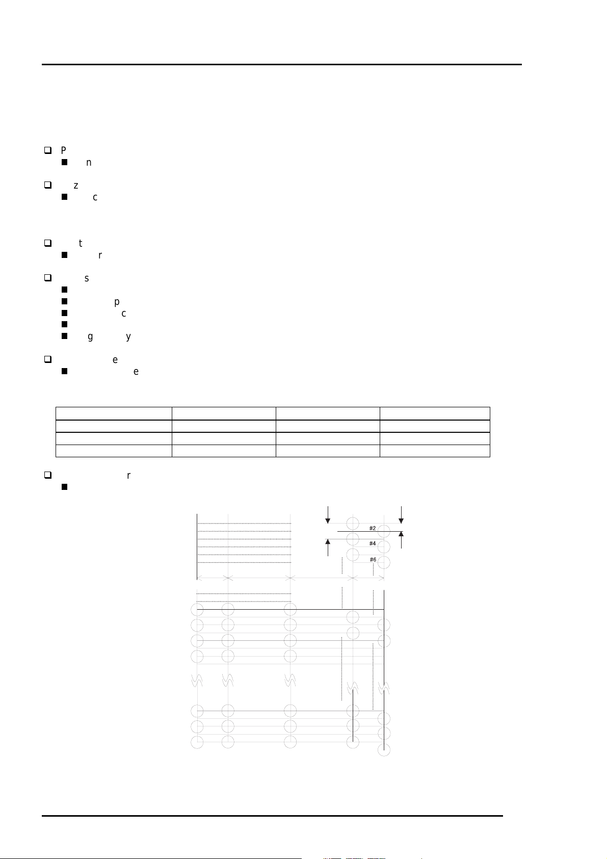
Nozzle configuration
Refer to figure 1-1.
#1
180DPI
2.2578 mm
Y1
Y2
Y3
Y4
10.16 mm
M 1
M 2
M 3
M 4
7.9022 mm
C1
C2
C3
C4
90DPI
#3
#5
#23
#25
2.2578 mm
#24
#26
#59
#61
#63
(B2)
#60
#62
#64
(B1)
(Y)
Y19
Y20
Y21
(M)
M 19
M 20
M 21
C19
C20
C21
(C)
Figure1-1. Stylus Color 400 Nozzle
Configuration
1-
Rev. A
Page 4

3
Feeding method
Friction feed with ASF
Paper feed resolution
0.035mm(1/720 inch)
Line spacing
1/6 inch or programmable at 1/360 inch
Paper path
Cut-sheet ASF(Top entry)
Feeding speed
66.6ms (1/6 inch)
153.7ms (9.03mm line spacing)
76.2ms (continues 3.0 inch/sec)
Ink supply
Exclusive ink cartridge(Black and CMY)
Paper holding capacity of Hopper
Size : Index card ∼Legal
Thickness : Less than 8mm
Paper capacity : 100 Cut sheets
: 10 Envelopes
: 65 Coated papers (360 dpi)
: 65 Coated papers (720 dpi)
: 30 Glossy papers
: 10 Transparent sheets
: 30 Index cards
EPSON Stylus Color 400 Service Manual
Note)
Those numbers above should be considered as reference. The actual paper accumulation should
be considered first.
Character tables : 2 international character sets(Not Opened)
PC437(US, Standard Europe)
PC850(Multilingual)
Typeface
Bit map LQ font : EPSON Courier 10CPI
Control code
ESC/P Raster
EPSON Remote command
Rev. A
1-
Page 5

Chapter1 Product Description
4
1.2.2 Paper Specification
This section describes the printable area and types of paper that can be used in this printer.
1.2.2.1 Cut Sheet
[Size]
[Thickness]
[Weight]
[Quality]
: A4 [Width 210mm(8.3”) x Length 297mm(11.7”)]
: Letter [Width 216mm(8.5”) x Length 279mm(11.0”)]
: B5 [Width 182mm(7.2”) x Length 257mm(10.1”)]
: Legal [Width 216mm(8.5”) x Length 356mm(14.0”)]
: Statement [Width 139.7mm(5.5”) x Length 215.9mm(8.5”)]
: Exclusive [Width 190.5mm(7.5”) x Length 254mm(10”)]
: 0.08mm(0.003”) - 0.11mm(0.004”)
2
: 64g/m
: Exclusive paper, Bond paper, PPC
(17Ib.) - 90g/m2(24Ib.)
1.2.2.2 Transparency, Glossy Paper
[Size]
[Thickness]
Note)
Transparency printing is only available at normal temperature.
: A4[Width 210mm(8.3”) x Length 297mm(11.7”)]
: Letter[Width 216mm(8.5”) x Length 279mm(11.0”)]
: 0.075mm(0.003”) - 0.085mm(0.0033”)
1.2.2.3 Envelope
[Size]
[Thickness]
[Weight]
[Quality]
Note 1)
Note 2)
Envelope printing is only available at normal temperature.
Keep the longer side of the envelope horizontally at setting.
: No.10 Width 241mm(9 1/2”) x Length 104.8mm(4 1/8”)
: DL Width 220mm(8.7”) x Length 110mm(4.3”)
: C6 Width 162mm(6.4”) x Length 114mm(4.5”)
: 0.16mm(0.006”) - 0.52mm(0.02”)
: 45g/m
: Bond paper, Plain paper, Air mail
1.2.2.4 Index Card
[Size]
[Thickness]
Note 1)
Note 2)
Note 3)
No curled, wrinkled, scuffing or torn paper be used.
Set the lever to the proper position according to the paper type you print. (Refer to section
1.2.3 for details)
Printing should be performed at room temperature in spite of the paper types.
: A6 Index card: Width 105mm(4.1”) x Length 148mm(5.8”)
: A5 Index card: Width 148mm(5.8”) x Length 210mm(8.3”)
: 5x8” Index card: Width 127mm(5.0” x Length 203mm(8.0”)
: 10x8” Index card: Width 127mm(5.0”) x Length 203mm(8.0”)
: Less than 0.23mm(0.0091”)
2
(12Ib.) - 75g/m2 (20Ib.)
1-
Rev. A
Page 6
EPSON Stylus Color 400 Service Manual
5
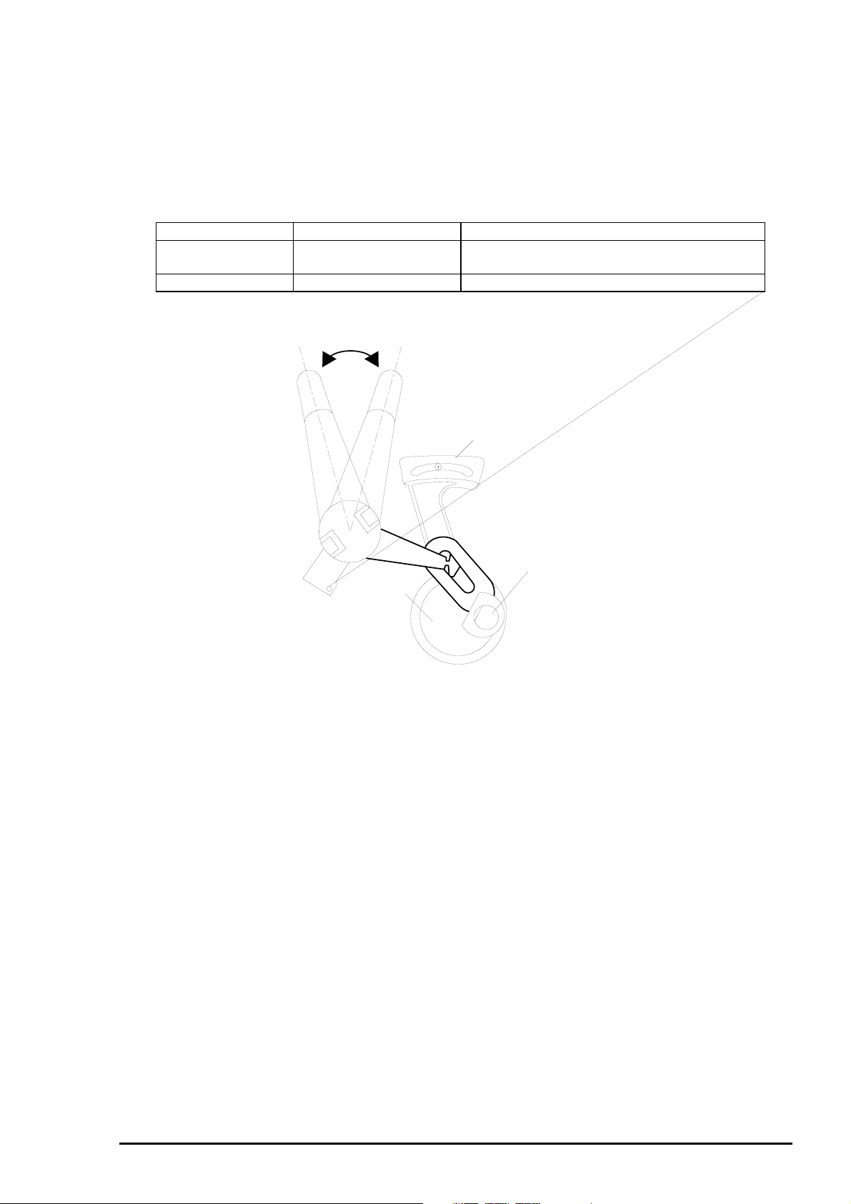
1.2.3 Adjust Lever Settings (PG adjust lever)
The adjust lever located on the right side(blue) under the printer cover needs to be set to the proper
position according to the paper you print. (Refer to the table below). Also, if there is any dirt caused by
friction on the wavy or wrinkled paper, this can be prevented by changing the lever position to rear
position (marked with “+”) in spite of paper types.
Table 1-3.Adjust Lever Settings
Paper Lever position PG adjustment value
Normal paper,
Coated paper
Envelopes Rear 0.9 mm (2.0mm between head and platen)
Front (Mark "0")
Front 0 mm (1.1mm between head and platen)
+
Rear (Mark "
")
Level adjustment lever
CR Guide Shaft
Bush
Figure 1-2. Adjust Lever Settings
Rev. A
1-
Page 7
Chapter1 Product Description
6
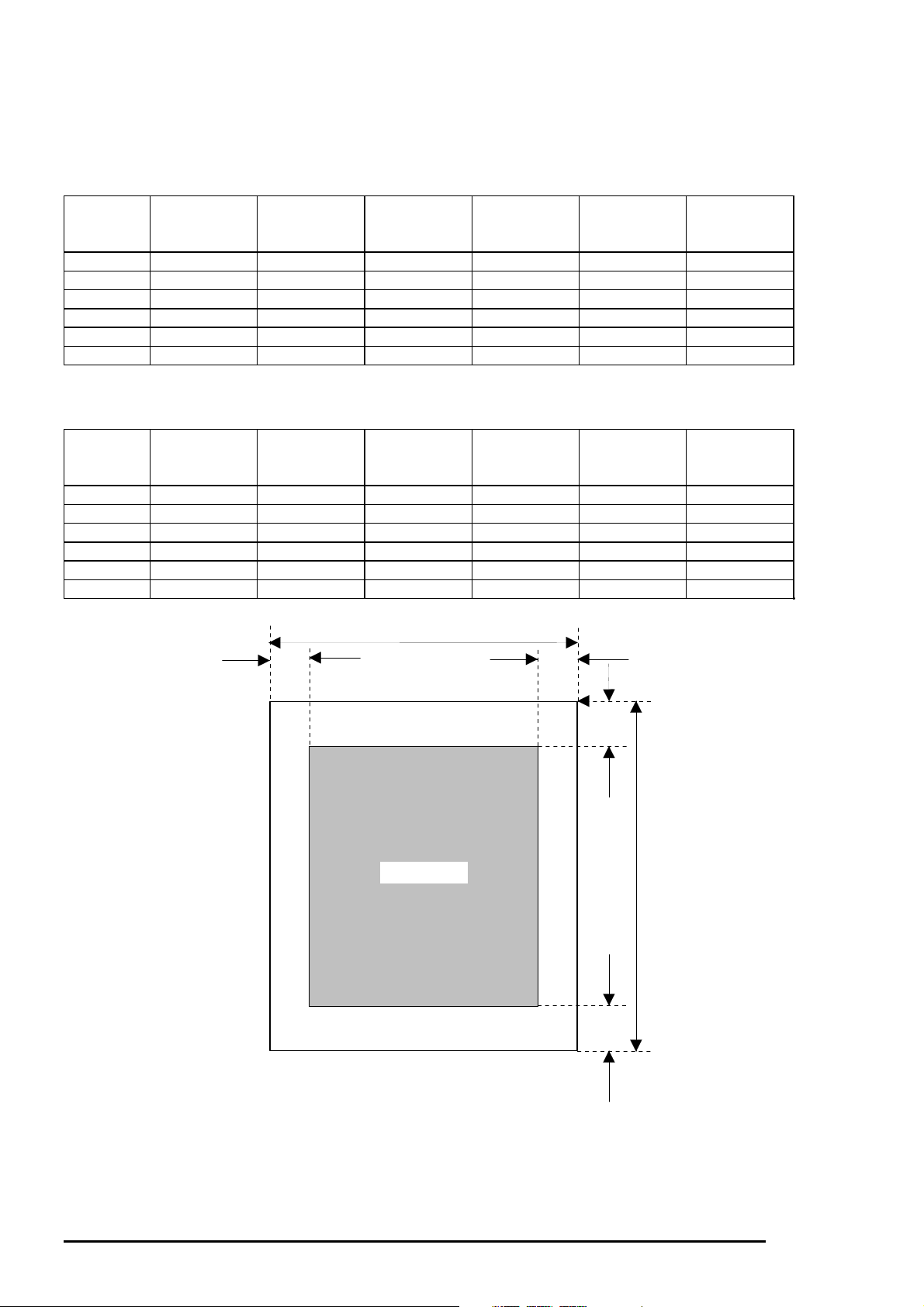
1.2.4 Printing Area
[Cut Sheet]
Following tables show printable areas at Character mode and Raster Graphics mode.
Table 1-4. Character Table
Paper size PW(Paper
width)
(typ)
PL(Paper
Length)
(typ.)
LM(Left
margin)
(min.)
RM(Right
margin)
(min.)
TM(Top
margin)
(min.)
BM(Bottom
margin)
(min.)
A4 210mm(8.3”) 297mm(11.7”) 3mm(0.12”) 3mm(0.12”) 3mm(0.12”) 14mm(0.54”)
Letter 216mm(8.5”) 279mm(11.0”) 3mm(0.12”) 9mm(0.35”) 3mm(0.12”) 14mm(0.54”)
B5 182mm(7.2”) 257mm(10.1”) 3mm(0.12”) 3mm(0.12”) 3mm(0.12”) 14mm(0.54”)
Legal 216mm(8.5”) 356mm(14.0”) 3mm(0.12”) 9mm(0.35”) 3mm(0.12”) 14mm(0.54”)
Statement 139.7mm(5.5”) 215.9mm(8.5”) 3mm(0.12”) 3mm(0.12”) 3mm(0.12”) 14mm(0.54”)
Executive 190.5mm(7.5”) 254mm(10”) 3mm(0.12”) 3mm(0.12”) 3mm(0.12”) 14mm(0.54”)
Table 1-5. Raster Graphics Mode
Paper size PW(Paper
width)
(typ)
PL(Paper
Length)
(typ.)
LM(Left
margin)
(min.)
RM(Right
margin)
(min.)
TM(Top
margin)
(min.)
BM(Bottom
margin)
(min.)
A4 210mm(8.3”) 297mm(11.7”) 3mm(0.12”) 3mm(0.12”) 3mm(0.12”) 14mm(0.54”)
Letter 216mm(8.5”) 279mm(11.0”) 3mm(0.12”) 3mm(0.12”) 3mm(0.12”) 14mm(0.54”)
B5 182mm(7.2”) 257mm(10.1”) 3mm(0.12”) 3mm(0.12”) 3mm(0.12”) 14mm(0.54”)
Legal 216mm(8.5”) 356mm(14.0”) 3mm(0.12”) 3mm(0.12”) 3mm(0.12”) 14mm(0.54”)
Statement 139.7mm(5.5”) 215.9mm(8.5”) 3mm(0.12”) 3mm(0.12”) 3mm(0.12”) 14mm(0.54”)
Executive 190.5mm(7.5”) 254mm(10”) 3mm(0.12”) 3mm(0.12”) 3mm(0.12”) 14mm(0.54”)
PW
LM RM
Printable Area
Figure 1-3. Printing Area for Cut Sheets
TM
PL
BM
1-
Rev. A
Page 8
EPSON Stylus Color 400 Service Manual
7
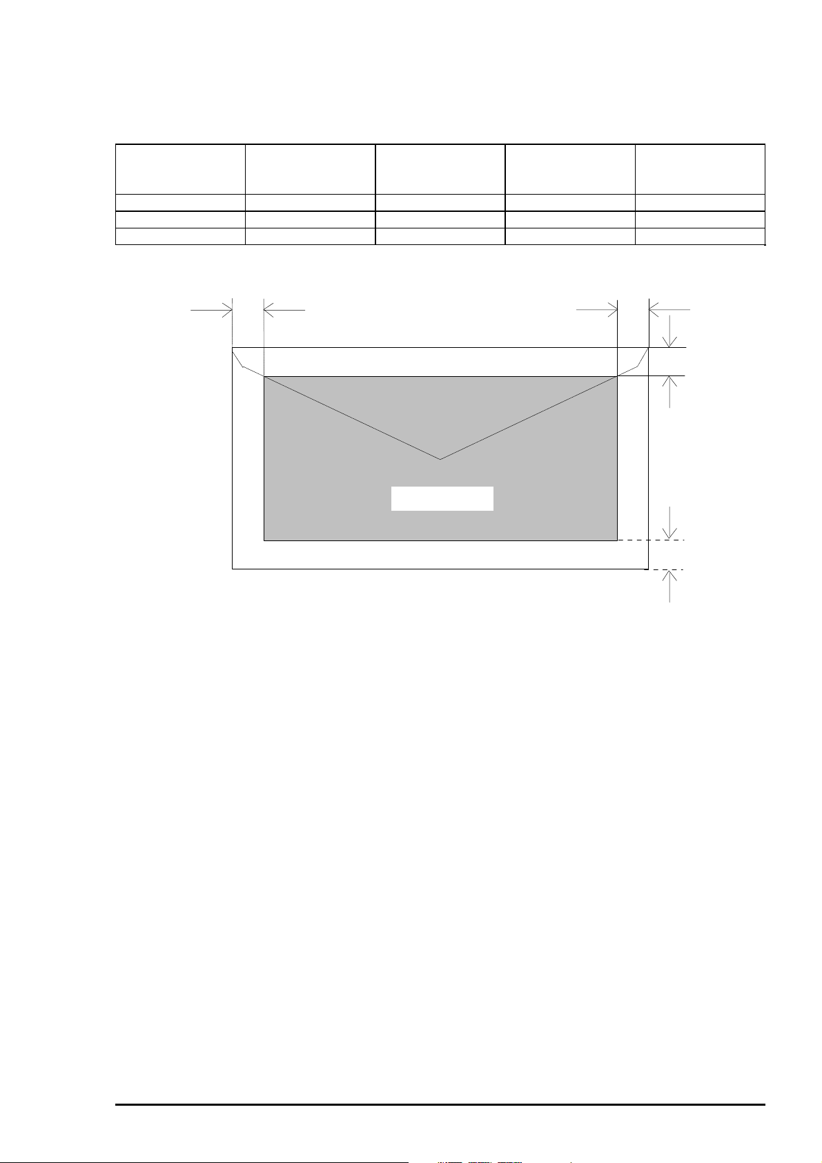
[Envelope]
The table and figure below show the printable area for envelopes.
Table 1-6. Printable Area for Envelope
Paper size LM(Left margin)
(min.)
#10 3mm(0.12”) 28mm(1.10”) 3mm(0.12”) 14mm(0.55”)
DL 3mm(0.12”) 7mm(0.28”) 3mm(0.12”) 14mm(0.55”)
C6 3mm(0.12”) 3mm(0.12”) 3mm(0.12”) 14mm(0.55”)
LM
RM(Right margin)
(min.)
TM(Top margin)
(min.)
BM(Bottom
margin)
(min.)
RM
TM
Printable area
Figure 1-4. Printing Area for Envelope
BM
Rev. A
1-
Page 9

Chapter1 Product Description
8
1.2.5 Environmental Condition
Temperature
Operating :10 to 35 °C (Refer to the figure below for condition)
Non-operating : -20 to 60 °C(with shipment container)
Note)
1 month at 40 °C and 120 hours at 60 °C
Humidity
Operating : 20% 80% RH (without condensation. Refer to the figure below for
condition)
Non-operating : 5% 85% RH (without condensation and with shipment container)
Humidity
(% RH)
80%
55%
20%
Guaranteed range
Resistance to shock
Operating : 1G, within 1 ms X,Y,Z directions
Non-operating : 2G, within 2 ms X,Y,Z directions (with shipment container)
Resistance to vibration
Operating : 0.15G, 1055Hz X,Y,Z directions
Non-operating : 0.50G, 1055Hz X,Y,Z directions (with shipment container)
Note 1)
Note 2)
During non-operating, make sure that the head is capped.
During the transport, make sure that the head is capped and ink cartridge is
installed to the printer.
Note 3)
If the head is not capped at the power-off state, turn the power on with installed ink
cartridge and turn off the power after confirming that Power on operation is completed and
the head is capped.
Note 4)
Ink will be frozen under -4°C environment, however it will be useable after placing it
more than 3 hours at 25°C.
10°C
(50°F)
27°C
(80°F)
35°C
(95°F)
°C
(°F)
Figure 1-5. Temperature/Humidity of Range
1-
Rev. A
Page 10

EPSON Stylus Color 400 Service Manual
9
1.2.6 Ink Cartridge Specifications
[Black Ink Cartridge]
Table 1-7.Black Cartridge Specification
Item Specifications
Type Exclusive cartridge
Color Black
Print capacity 540 pages / A4 (ISO/IE10561 Letter Pattern at 360 dpi)
Validity 2 years (sealed in package) / 6months(out of package)
Environmental
conditions
Dimension 19.8mm(W) x 52.7(D) x 38.5mm(H)
Weight
Temperature
Storage : -20°C40°C(within a month at 40°C)
Packing storage : -30°C40°C (within a month at 40°C)
Transit : -30°C60°C (within 120 hours at 60°C and within a
month at 40°C)
Humidity
5%85%(without condensation)
Resistance to vibration
Sealed in package : 555Hz
Acceleration : 29.4m/s less than <3G>
Direction : X, Y, Z direction
Time : 1 hour
Drop
Sealed in package :
Dropping height : Less than 0.08m
Direction : Drop the printer facing the bottom, sides and one
edge down.
Out of package:
Dropping height : Less than 1.50m
Frequency : Once
Total ink cartridge : 54g
Total ink : 16.4 ± 0.5g (Quantity in the ink cartridge)
Consumable ink : More than 12.1g(Useable ink quantity until ink ends)
Note 1)
Note 2)
Note 3)
Ink cartridge can not re-fill, only ink cartridge is prepared for article of consumption.
Do not use the ink cartridge which is passed away the ink life.
Ink will be frozen under -4°C environment, however it will be usual after placing it more than
3 hours at room temperature.
Figure 1-6. Ink Cartridge (Black)
19.8
52.7
18.3
51.2
38.5
Rev. A
1-
Page 11

Chapter1 Product Description
0
[Color Ink Cartridge]
Table 1-8. Color Ink Cartridge Specification
Item Specifications
Type Exclusive cartridge
Color Magenta, Cyan, Yellow
Print capacity 320 pages / A4 (360 dpi, 5% duty each color)
Validity 2 years (sealed in package) / 6months(out of package)
Environmental
conditions
Temperature
Storage : -20°C40°C (within a month at 40°C)
Packing storage : -30°C40°C (within a month at 40°C)
Transit : -30°C60°C (within 120 hours at 60°C and within a month
at 40°C)
Humidity
5%85%(without condensation)
Resistance to vibration
Sealed in package : 555Hz
Acceleration : 29.4m/s less than <3G>
Direction : X, Y, Z direction
Time : 1 hour
Drop
Sealed in package :
Dropping height : Less than 0.08m
Direction : Drop the printer facing the bottom, sides and one
edge down.
Out of package:
Dropping height : Less than 1.50m
Frequency : Once
Dimension 42.9mm(W) x 52.7(D) x 38.5mm(H)
Weight
Total ink cartridge : 68g
Total ink : 13.3 0.5g (Quantity in the ink cartridge)
Consumable ink : More than 10.1g/each color(Useable ink quantity until
ink ends)
Note 1)
Note 2)
Note 3)
Ink cartridge can not re-fill, only ink cartridge is prepared for article of consumption.
Do not use the ink cartridge which is passed away the ink life.
Ink will be frozen under -4°C environm ent, however it will be usual after placing it more than
3 hours at room temperature.
43.2
51.2
42.9
41.4
52.7
38.5
Figure 1-7. Ink Cartridge (Color)
1-1
Rev. A
Page 12

1.2.7 Physical Specification
EPSON Stylus Color 400 Service Manual
[Dimension]
[Weight]
: 429mm(W) x 234mm(D) x 162mm(H)
: 429mm(W) x 695mm(D) x 309mm(H) with extended stacker and paper support.
: 5.2Kg
1.2.8 Input Data Buffer
10 K byte
Rev. A
1-11
Page 13

Chapter1 Product Description
2
1.2.9 Electric Specification
[120V version]
[Rated voltage] : AC120V
[Input voltage range] : AC103.5∼132V
[Rated frequency range] : 50∼60Hz
[Input frequency range] : 49.5∼60.5Hz
[Rated current] : 0.4A(Max. 0.5A)
[Power consumption] : Approx.15W(ISO/IEC 10561 Letter pattern)
: Energy Star compliant
[Insulation Resistance] : 10M ohms min.(between AC line and chassis, DC500V)
[Dielectric strength] : AC1000 V rms. 1 minute or AC1200 Vrms. 1 second (between AC
line and chassis)
[220∼240V version]
[Rated voltage] : AC220V∼240V
[Input voltage range] : AC198∼264V
[Rated frequency range] : 50∼60Hz
[Input frequency range] : 49.5∼60.5Hz
[Rated current] : 0.2 A(Max. 0.3A)
[Power consumption] : Approx.15W(ISO/IEC 10561 Letter pattern)
: Energy Star compliant
[Insulation Resistance] : 10M ohms min.(between AC line and chassis, DC500V)
[Dielectric strength] : AC1500 V rms. 1 minute (between AC line and chassis)
1.2.10 Reliability
[Total print volume] : 10,000 pages(A4, letter)
[Print head life] : 2000 million dots/nozzle
1.2.11 Safety Approvals
[120V version]
Safety standard : UL1950 with D3
EMI : FCC part 15 subpart B class B
[220∼240V]
Safety standard : EN 60950(VDE,NEMKO)
EMI : EN55022(CISPR Pub.22) class B
1-1
: CSA22.2 No.950 with D3
: CSA C108.8 class B
: AS/NZS 3548 class B
Rev. A
Page 14

3
1.2.12 Acoustic Noise
[Level] : Approx.45 dB(A) (According to ISO 7779)
1.2.13 CE Marking
[220-240V version]
Low voltage Directive 73/23/EEC :EN60950
EMC Directive 89/336/EEC :EN55022 Class B
EN61000-3-2
EN61000-3-3
EN50082-1
IEC801-2
IEC801-3
IEC801-4
1.2.14 Printer Language and Emulation
[Printer Language] : ESC/P Raster
: EPSON Remote
EPSON Stylus Color 400 Service Manual
[ESC/P control codes]
< Character mode >
General Operation
Initialize Printer : ESC@
Paper feeding
Form Feed : FF
Line Feed : LF
Carriage Return : CR
<Graphic mode>
General operation
Initialize Printer : ESC@
Unidirectional Printing : ESC U
CSF Mode Control : ESC EM
Paper feeding:
Form Feed : FF
Line Feed : LF
Line Spacing : ESC+
Carriage Return : CR
Page format
Page Length : ESC(C
Top/Bottom Margin : ESC(c
Print position motion
Horizontal Print Position : ESC$,ESC\
Vertical Print Position : ESC (V,ESC (v
Spacing
Define Unit : ESC(U
Graphics
Graphics Mode : ESC(G
Raster Graphics : ESC.
Micro weave control : ESC(i
Printing mode
Printing mode : ESC(K
Rev. A
1-1
Page 15

Chapter1 Product Description
4
Color
Printing color : ESC r, ESC(r
EEPROM control
EEPROM control : ESC
1-1
Rev. A
Page 16

5
1.3 Interface
This printer provides parallel interface as standard.
1.3.1 Parallel Interface (Forward Channel)
EPSON Stylus Color 400 Service Manual
[Transmission mode]
[Synchronization]
[Handshaking]
[Signal level]
[Adaptable connector]
BUSY signal is set high before setting either/ERROR low or PE high and held high until all these
signals return to their inactive state.
BUSY signal is at high level in the following cases.
During data entry (see Data transmission timing)
When input data buffer is full
During -INIT signal is at low level or during hardware initialization
During printer error (See /ERROR signal)
/ERROR signal is at low level when the printer is in one of the following states.
Printer hardware error (fatal error)
Paper-out error
Paper-jam error
Ink-out error
PE signal is at high level during paper-out error.
Table 1-9 shows the signal and connector pin assignments for parallel interface(forward channel*1).
In case of these signals, twist pair line is used and returning side is connected to signal GND.
(*1): Forward channel is the mode when the ordinary data such as an order to print is sent
from the PC to the printer.
: 8 bit parallel, IEEE-1284 compatibility mode
: By /STOPBE pulse
: BY BUSY and /ACKLG signal
: TTL compatible level
: 57-30360(amphenol) or equivalent
Table 1-9. Signal and Connector Pin Assignment for Parallel Interface
Pin No. Signal Name Return GND pin In/Out Functional Description
1 /STROBE 19 In The strobe pulse. Read-in of data is performed
at the falling edge of this pulse.
2-9 DATA0-7 20-27 In The DATA0 through DATA7 signals represent
data bits 0 to 7, respectively. Each signal is at
high level when data is logical 1 and low level
when data is logical 0.
10 /ACKNLG 28 Out This signal is a negative pulse indicating that
the printer can again accept data.
11 BUSY 29 Out A high signal indicates that the printer cannot
receive data.
12 PE 28 Out A high signal indicates paper-out error.
13 SLCT 28 Out Always at high level when the printer is
powered on.
14 /AFXT 30 In Not used.
31 /INIT 30 In The falling edge of a negative pulse or a low
signal on this line causes the printer to
initialize. Minimum 50 us pulse is necessary.
32 /ERROR 29 Out A low signal indicates printer error condition.
36 /SLIN 30 In Not used.
18 Logic H - Out Pulled up to +5V via 3.9K ohm resistor.
35 +5V - Out Pulled up to +5V via 3.3K ohm resistor.
17 Chassis GND - - Chassis GND.
16,33,19-30 GND - - Signal GND.
15,34 NC - - Not connected.
Note)
In/Out refers to the direction of signal flow from the printer’s point of view.
Rev. A
1-1
Page 17

Chapter1 Product Description
6
1.3.2 Parallel Interface (Reverse Channel)
[Transmission mode]
[Synchronization]
[Handshaking]
[Data trans. timing]
[Signal level]
[Adaptable connector]
[Extensibility request]
Note)
The printer sends following device ID string when it is requested.
: IEEE-1284 nibble mode
: Refer to the IEEE-1284 specification
: Refer to the IEEE-1284 specification
: Refer to the IEEE-1284 specification
: IEEE-1284 level 1 device
: TTL compatible level
: 57-30360(amphenol) or equivalent
: The printer responds affirmatively when the extensibility
request values are 00H or 04H, that mean,
00H :Request Nibble Mode Reverse Channel Transfer.
04H :Request device ID; Return Data using Nibble Mode Rev
Channel Transfer.
Table 1-10. Device ID Description
00H
<
> <
MFG EPSON Production Maker
CMD ESCPL2,BDC Command system
MDL Stylus[SP]Color[SP] 400 Model name
CLS PRINTER Class
Note)
[00H] denotes a hexadecimal value of zero. MDL value depends on the EEPROM setting.
Note)
MDL value depends on the EEPROM setting. Model name can be changed by changing a
certain address in the EEPROM.
The table below shows pin assignment for reverse channel(*3). In these case of signals, twist pair line
is used and returning side is connected to Signal GND.(*3): Reverse channel is the mode that any data is
transferred from the printer to the PC.
Table 1-11. Pin Assignment for Reverse Channel
Pin No. Signal Name Return
1 HostClk 19 In Host clock signal.
2-9 Data0-7 20-27 In The DATA0 through DATA7 signals
10 PrtClk 28 Out Printer clock signal.
11 PtrBusy, Data Bit-3,7 29 Out Printer busy signal and reverse
12 AckDataReq, DataBit-2,6 28 Out Acknowledge data request signal and
13 Xflag, DataBit-1,5 28 Out X-flag signal and reverse channel
14 HostBusy 30 In Host busy signal.
31 /INIT 30 In Not used.
32 /DataAvail, DataBit-0,4 29 Out Data available signal and reverse
36 1284-Active 30 In 1284 active signal.
18 Logic-H - Out Pulled up to +5V via 3.9K ohm resister.
35 +5V - Out Pulled up to +5V via 3.3K ohm resister.
17 Chassis GND - - Chassis GND.
16,33,19-30 GND - - Signal GND.
15,34 NC - - Not connected.
3CH
GND pin
>
In/Out Functional description
Contents
represent data bits 0 to7, respectively.
Each signal is at high level when data
is logical 1 and low level when data is
logical 0. These signals are used to
transfer the 1284 extensibility request
values to the printer.
channel transfer data bit 3 or 7.
reverse channel transfer data bit 2 or
6.
transfer data bit 1 or 5.
channel transfer data bit 0 or 4.
Note)
In/Out refers to the direction of signal flow from the printer’s point of view.
1-1
Rev. A
Page 18

7
Following lists “Notes” when using Parallel Interface.
EPSON Stylus Color 400 Service Manual
Note1) “
Return GND pin” in the table means twist pair return and is used for all control signals
except for Logic H,+5V, Chassis, GND and NC. In this twist pair return, returning side
is connected to GND (16,33, 19-30 pin) for twist pair return. Also, these cables are shielded
wires and it is effective to connect to each chassis GND in the PC and printer for electrostatic
noise.
Note2)
Conditions for Interface are based on TTL level. Rise and fall time should be within 0.2µs.
Note3)
Note4)
Refer to the figure 1-8 for transmission timing of each signals.
Do not perform data transmission ignoring /ACK or BUSY signal. (Perform the data transmission
after confirming that /ACK and BUSY signals are Low.)
Note5)
It is possible to perform the printing test including interface circuit without using equipment
from outside when 8-bit data signal(20-27 pin) is set to appropriate word code and connect
them forcefully to /ACK and /STRB.
[Data Transmission Timing for Forward Channel]
Data
/STROBE
BUSY
Byte Data n Byte Data n+1
Thold
Tsetup
Tstrb
Tnext
/ACKNLG
Tready Tbusy
Figure 1-8. Parallel Interface Timing Chart(Forward Channel)
Table 1-12. Maximum and Minimum Timing for Data Transmission
Parameter Minimum Maximum
tsetup 500ns ---
thold 500ns ---
tstb 500ns ---
tready 0 ---
tbusy --- 500ns
tt-out* --- 120ns
tt-in** --- 200ns
treply 0 ---
tack 500ns 10us
tnbusy 0 ---
tnext 0 -- * Rise and fall time of every output signals.
** Rise and fall time of every input signals.
Typical time of tack is shown below.
Treply
Tack Tnbusy
Table 1-13. Typical Time of Tack
Parallel I/F mode Typical time of tack
High speed 2us
Normal speed 4us
Rev. A
1-1
Page 19

Chapter1 Product Description
8
[Signal level: TTL compatible (IEEE-1284 level 1 device)]
Table 1-14. Signal Level
Parameter Minimum Maximum Condition
VOH* --- 5.5V
VOL* -0.5V ---
IOH* --- 0.32mA VOH = 2.4V
IOL --- 12mA VOL = 0.4V
CO --- 50pF
VIH --- 2.0V
VIL 0.8V ---
IIH --- 0.32mA VIH = 2.0V
IIL --- 12mA VIL = 0.8V
CI --- 50pF
*A low logic level on the Logic H signal is 2.0V or less when the printer is powered off and this
signal is equal or exceeding 3.0V when the printer is powered on. The receiver shall provide an
impedance equivalent to 7.5K ohm to ground.
[Data Transmission Timing for Reverse Channel]
The figure below shows timing chart of Parallel Interface Reverse channel.
Virtual Busy Status
Virtual Busy Status
Figure 1-9. Parallel Interface Timing Chart(Reverse Channel)
1.3.3 Prevention Hosts from Data Transfer time-out
Generally, hosts abandon data transfer to peripherals when a peripheral is in the busy state
for dozens of seconds continuously. To prevent hosts this kind of time-out, the printer receives
data very slowly, several bytes per minute, even if the printer is in busy state. This showdown
is started when the rest of the input buffer becomes several hundreds of bytes. Finally, the printer is
in the busy state continuously when the input buffer is full.
1-1
Rev. A
Page 20

EPSON Stylus Color 400 Service Manual
9
1.4 Control Panel
Since Stylus Color 400 does not require many buttons since printer driver can start various settings and
motions. Therefore, there are only 2 non-lock type push switches, 1 lock type push switch and 4 LEDs.
Following figure shows control panel of Stylus Color 400.
Power LED
Paper Out LED
Ink Out(Bk) LED
Ink Out(CMY) LED
Cleaning Switch
(Ink maintenance)
Load/Eject Switch
Power on Switch
Figure 1-10. Control Panel
1.4.1 Indicators
(1) Power
Lights when the operate switch is “ON”, and AC power is supplied.
(2) Paper out
Lights during the paper-out condition, and blinks during the paper-jam condition.
(3) Ink Out (Black)
Lights during no Black ink condition, and blinks during the Black ink low condition.
(4) Ink Out (Color)
Lights during no Color ink condition, and blinks during the Color ink low condition.
Rev. A
1-1
Page 21

Chapter1 Product Description
0
1.4.2 Panel Functions
Panel Functions
<
Switch Function
Load/Eject
(Pushing within 2 seconds*)
Load/Eject
(Pushing for 2 seconds*)
Cleaning
(Pushing for 2 seconds*)
Cleaning
(Pushing within 2 seconds*)
Note)
** This function is not available in printing status.
Panel Functions with Power ON
<
* 3 seconds is required at the User’s manual.
>
Table 1-15. Panel Function
Loads or Eject the paper.
When carriage is on the Ink Cartridge change position, return carriage
from Ink Cartridge change position.
Starts the Ink Cartridge change sequence.**
Moves the carriage to cartridge change position.
Stars the Cleaning of head.
In the condition of “Ink Low” or “Ink Out” or “No Ink Cartridge” starts
the Ink Cartridge change sequence.**
When carriage is on the Ink Cartridge change position, return carriage
from Ink Cartridge change position.
>
Table 1-16. Panel Function with Power On
Switch Function
Load/Eject
Cleaning
Load/Eject
+
Cleaning
Note) **
Maintenance Error Reset
<
Note)
status printings prints firmware version, ink counter, selected code page and nozzle check
patterns.
Switch Function
Cleaning
The next page explains the detail procedure of the EEPROM reset.
Stars status printings.**
Changes a Code Page.
Enters the particular settings mode. (Factory use only.)
To enter the particular settings mode, it is necessary to push the
cleaning switch while Paper Out LED is blinking.(It blinks about 3
seconds)
>
Table 1-17. Particular Setting Mode
Initialize EEPROM and reset timer IC.
1-2
Rev. A
Page 22

EPSON Stylus Color 400 Service Manual
[Maintenance Error Reset Procedure]
You can reset the maintenance error by pressing the cleaning switch after you enter the particular setting
mode(Refer to table 1-15.) There are no function which can be reset the all address in EEPROM on the
Stylus Color 400. Followings are detail procedure of maintenance error reset operation.
WARNING
Stylus Color 400 does not have “All Clear function” for EEPROM like other printers. Therefore,
it is not necessary to replace the new ink cartridge after you perform this reset operation.
Be sure to replace a waste ink pad in the printer enclosure with a new one after you perform this
maintenance error reset operation.
[Step 1] By pushing Load/Eject and Cleaning switches at the same time, turn on the switch.
(By operating this performance, the LED for paper out starts blinking.<3-seconds only>)
[Step 2] Push the cleaning switch while the LED for Paper Out is blinking (3 seconds).
Note) If the printer accepts this function correctly, it returns to the standby mode after the
Maintenance LEDs(both Black and CMY) blink for 1 second. Following shows the lists that will
be cleared by this performance.
1. Maintenance Error Reset
2. Time IC Reset
3. I/F selection (returns to AUTO)
*** The value of ink counter, Bi-D adjustment, VH voltage are not cleared. ***
Rev. A
1-21
Page 23

Chapter1 Product Description
2
1.4.3 Printer Condition and Panel Status
The table below shows printer condition and panel status. Since this table shows various error
status and also present printer status, you can judge appropriate repair ways from this table.
Table 1-18. Printer Condition and Panel Status
Indicators
Printer status Power Ink Out
(Black)
Power on condition On --- --- --- 9
Ink sequence Blink --- --- --- 6
Ink Cartridge change
mode
Data processing Blink --- --- --- 8
Paper Out --- --- --- On 4
Paper jam condition --- Off Off Blink 3
No Ink cartridge or Ink
end(black)
Ink level low(black) --- Blink --- --- 7
No Ink cartridge or Ink
end(color)
Ink level low(color) --- --- Blink --- 7
Enter EEPROM and
Timer IC reset
Maintenance request Blink Blink Blink Blink 2
Fatal error Blink On On Blink 1
Blink --- --- --- 5
--- On --- --- 7
--- --- On --- 7
--- On
(1 second only)On(1 second only)On(1 second only)
Ink Out
(Color)
Paper Out Priority
--
Note1*)
Note2*)
Note3*)
: Refer to section 1.3.3 for error status.
: It does not mean that all address would be cleared.
: -- means no changes.
1-2
Rev. A
Page 24

EPSON Stylus Color 400 Service Manual
3
1.5 Error Status
When following status occur, the printer goes to the error status and stops taking data, setting
the /ERROR signal in the interface as “Low”, and Busy signal as “High”. At this time, the printer
goes to non printable status. Refer to section 1.4.3 for more details of LED Panel indicators during
the various error status.
1.5.1 Ink Out
When the printer runs out the most part of the ink of any one color, it warns ink-low and keeps printing.
When the printer runs out the whole ink of any one color, it stops printing and indicates ink-out error.
User is requested to install a new ink-cartridge in this state. A ink-cartridge once taken out should
never be used again. Re-installation of the cartridge not filled fully upsets the ink level detection and
may cause a serious problem in the print head as a result.
WARNING
Never use the ink cartridge once taken out.
Following explains above warning sign.
[Step 1]
[Step 2]
[Step 3]
After the cartridge is once taken out, bubbles come in from the ink supply hole located at
the top of cartridge and are absorbed into the head during printing performance.
Therefore, the head will be unable to discharge the ink properly. Also, inevitable
entering of bubbles when installing a new ink cartridge can be absorbed to ink itself since
the ink itself in the cartridge is deaerated during the production process.
However, this absorbing ability can last only about one hour after the cartridge is installed.
Even after the bubble absorbing ability described above stops, there is no worry about
entering bubbles as long as the ink cartridge is being installed to the printer.
However, if the ink cartridge which does not have absorbing ability any more is once
removed from the printer, new coming bubbles into the cartridge will never disappear
naturally. These bubbles may cause not only printing malfunction but also thickening ink.
This thickened ink goes into the head and clogs ink path in the head or nozzle and may
cause serious head damage.
As standard specification for Stylus Color 400, ink consumption counter is reset when
the ink cartridge is removed. If an ink cartridge is removed and re-installed unnecessarily
the value on the ink consumption monitor which the user can check will be wrong and
printer may keep printing even though the ink cartridge is installed empty.
This may cause head damage.
1.5.2 Paper Out
When printer fails to load a sheet after power on operation including timer-cleaning is done
and Load/Eject button on the FF command or operation panel is pressed, it goes paper out error.
1.5.3 Paper Jam
When printer fails to eject a sheet even after feeding motion is completed or Load/Eject button on
the FF command or operation panel is pressed, it goes paper jam error.
Rev. A
1-2
Page 25

Chapter1 Product Description
4
1.5.4 No Ink-Cartridge
Following reasons can be the causes when printer goes this error mode.
1) When the printer is turned on for the first time.
(This is a normal error state and it returns to the normal state after installing an ink cartridge
according to the ink cartridge exchange operation.)
2) Ink cartridge exchange operation is done correctly.
After the position of carriage is moved by exchange operation, if the cleaning switch is pushed without
installing ink cartridge or if the carriage returns to the home-position automatically without doing any
operation, it is considered as handling mistake. However, it returns to normal state by performing
ink exchange operation again and installing cartridge correctly.
3) If “No ink-cartridge error” appears even after the ink cartridge is installed, the printer must be
something wrong and around the sensor area in the carriage need to be repaired.
4) If sometimes printer can print normally but also sometimes “No ink-cartridge error” appears, the
printer must be something wrong. (Same reason as 3) above)
1.5.5 Maintenance Request
When the total quantity of ink wasted through the cleanings and flushing reaches to the limit, printer
indicates this error and stops. The absorber in the printer enclosure is needed to be replaced with
new one by a service person.
The ink quantity that is absorbed by the absorber (waste ink pad) is monitored by the software counter as
“total ink counter”. This counter is added by point system and absorber’s maximum ability is set at
the following reference value.
✳29500 X 0.0102 ml = Approximately 301 ml
1-point = 0.0102 ml (the value which is multiplied evaporating rate and 1-dot ink weight
0.02 ml)
29500 = Maximum point number (Maintenance error threshold)
However, considering dispersion of ink absorbing quantity and the number of using nozzles, ink total
value is calculated by the following formula.
✳301 X 1.1 ÷ 63% = 526 ml (but up to 532ml can be retained)
WARNING
When you perform self- test after completing repairs, it is possible to c heck the present value of total
ink counter and ink discharge conditions from all nozzles by performing status printing in the built-in
function. Therefore, make sure that the printer has enough v alue of total ink counter (if the number is
close to 29500 or not). If there is not enough value, the service man is required to judge if it is
necessary to clear EEPROM after replacing the absorber (waste ink pad) or not. Refer to section 1.4.2
if you need to perform EEPROM Clear.
1.5.6 Fatal Errors
When printer detects fatal errors such as carriage control error or CG access error, it goes to this
error mode. Refer to followings for each error.
1) Carriage control Error : Parallel adjustment malfunction, Home-position malfunction, Timing
belt tension malfunction, shortage of lubricant on the carriage guide shaft, etc.
2) CG Access Error : Short circuit, etc.
1-2
Rev. A
Page 26

EPSON Stylus Color 400 Service Manual
5
1.6 Printer Initialization
Stylus Color 400 has three kinds of initialization methods. Following explains each initialization.
[1.Power-on initialization]
This printer is initialized when turning the printer power on, or printer recognized the cold-reset
command (remote RS command).
When printer is initialized, following action is performed.
(a) Initializes printer mechanism.
(b) Clears input data buffer.
(c) Clears print buffer.
(d) Sets default values.
[2.Operator initialization]
This printer is initialized when turning the printer power on again within 10 seconds from last
power off, or printer recognize the /INIT signal (negative pulse) of parallel interface.
When printer is initialized, following action is performed.
(a) Cap the printer head.
(b) Eject a paper.
(c) Clears input data buffer.
(d) Clears print buffer.
(e) Sets default values.
[3. Software initialization]
The ESC@ command also initialize the printer.
When printer is initialized, following action is performed.
(a) Clears print buffer.
(b) Sets default values.
1.7 Initialization Settings
Stylus Color 400 initializes following settings when the initialization is performed. Also, if the user changes
the settings in the Panel setting, Default setting or Remote command setting, values or settings which
are possible to be stored are initialized as initialization settings.
Page position : Page heading location as present paper location
Line spacing : 1/6 inch
Right margin position : 80 lines
Left margin position : first line
Character pitch : 10CPI
Printing mode : Text mode (Not Raster graphics mode)
Rev. A
1-2
Page 27

Chapter1 Product Description
6
1.8 Main Components
Stylus Color 400 has following major units. Also, it is one of the major characteristics that the bottom of
the Printer mechanism plays the role as Lower case at the same time. Each units from 2) to 4) are
simply explained as following.
1) Upper case
2) Printer Mechanism
3) C206 Main control board
4) C206 PSB/PSE(Power Supply Board)
5) C206 PNL(Panel Board)
1.8.1 Printer Mechanism
Unlike EPSON’s previous ink jet printer mechanisms, one of the major characteristics of Stylus Color
400 is that the printer has no Engage/Dis-Engage mechanism in order to change over pump mechanism
and paper feeding mechanism. In stead, however, this change-over control is done by the distinction
between turning direction of PF/Pump motor and position of present carriage unit. Also, another major
characteristic is that print head is changed to be one unit combined with black and CMY.
Nozzle configuration for black is 64 nozzles (each line has 90-dpi and between #1-#2 has 180dpi).
On the other hand, CMY nozzle has 21 nozzles(90dpi) for each color. Following figure shows
exterior of mechanism.
1.8.2 C206 Main Control Board
C206 main control board controls Stylus Color 400 and consists of following major electric elements.
1) CPU (TMP95C061F) 5) EEPROM (3strings Serial Type:1K-bit)
2) Gate Array (E05B44BA) 6) LB1845 (Motor Driver)
3) Program ROM (EEPROM or MASK ROM) 7) With Heat Sink transistor A1469, C3746
4) D-RAM (1CAS/2WE Type: 1M-bit) (MACH head type)
PF Motor Driver(IC15)
CN10
(Pwer Supply)
CN7(PF Motor)
Trapezoidal Wave form Driver(IC6)
Carriage Motor Driver(IC14)
CN6(CR Motor)
1K-bit EEPROM(IC11)
CN8(Head Control)
Common Driver Transistor
(Q7,Q9 with Heat Sink)
Figure 1-11. Exterior of C206 Main Control Board
CN1(Parallel I/F Connector)
ASIC E05B44(IC2)
Reset for Power
(IC9)
Reset for Logic
(IC8)
CPU TMP95C061
(IC1)
CN2(RS422 Serial I/F)
Transceiver for
Serial I/F(IC16)
Dinamic RAM(IC4)
Program ROM(EP-ROM or MASK ROM)
Battery for
timer IC
CN3(Panel I/F)
CN5(CRHP Sensor)
CN4(PE Sensor)
CN11(ASF phase Sensor)
1-2
Rev. A
Page 28

EPSON Stylus Color 400 Service Manual
7
1.8.3 C206 PSB/PSE Power Supply Board
In the electric boards for Stylus Color 400, switching regulator method is used and supplies
stable logic and power voltages constantly. Also, since this C206PSB board has secondly type
switch for its circuit system, it is possible to keep supplying electricity to the C206 main control board
for 30 seconds even after the power switch is turned off.
Using this time difference, even when mis-operation is done by the user such as turning off the power
during the middle of printing work, it prevents thickened ink from attaching around the nozzle plate
by transferring the head to cap position.
PC1
Trans (T1)Q1 (FET)
C51
CN2
IC51
Fuse (F1)
CN1
Filter (L1)
C11
Figure 1-12. Exterior of C206 PSB/PSE Board
1.8.4 C206PNL(Panel) Board
Panel board (C206 PNL board) is located in the panel case where is in the right bottom of the front
printer and consists of 3 switches, 4 LEDs and 1 connector.
Figure 1-13. Exterior of C206 PNL Board
Rev. A
1-2
 Loading...