

Page 1

Chapter 3
Disassembly and Assembly
3.1 OVERVIEW............................................................................................................3-1
3.1.1 Precautions for Disassembling the Printer.......................................................................... 3-1
3.1.2 Tools........................................................................................................................................3-2
3.1.3 Specification for Screws........................................................................................................ 3-2
3.1.4 Service Checks After Repair.................................................................................................. 3-3
3.2 Disassembly Procedures.....................................................................................3-4
3.2.1 Removing the Housing ..........................................................................................................3-5
3.2.2 Removing the Board Assembly.............................................................................................3-6
3.2.3 Removing the Operation Panel............................................................................................. 3-8
3.2.4 Disassembling the Printer Mechanism................................................................................. 3-9
3.2.4.1 Removing the Print Head Unit................................................................................... 3-9
3.2.4.2 Removing the Absorber Tray Assembly ;A...............................................................3-11
3.2.4.3 Removing the Pump Assembly and Cap Assembly................................................3-12
3.2.4.4 Removing the CR Motor Assembly .........................................................................3-14
3.2.4.5 Removing the PF Motor Assembly.......................................................................... 3-16
3.2.4.6 Removing the ASF Assembly.................................................................................. 3-18
3.2.4.7 Removing the Carriage Assembly........................................................................... 3-21
3.2.4.8 Removing the PF Roller Assembly.......................................................................... 3-23
3.2.4.9 Removing the PE Paper Detector Assembly...........................................................3-25
3.2.4.10 Removing the HP Detector.................................................................................... 3-26
3.2.4.6.1 Removing the Paper Feed Roller Assembly ................................................ 3-19
3.2.4.6.2 Removing the Right and Left LD Roller Assembly.......................................3-20
Page 2
Chapter3 Disassembly and Assembly
3.1 OVERVIEW
This section describes procedures for disassembling the main components of EPSON Stylus Color 400.
Unless otherwise specified, disassembly units or components ca be reassembled by reversing the
disassembly procedure. Therefore, no assembly procedures are included in this section. Precautions for
any disassembly or assembly procedure are described under the heading “WORK POINT”. Any
adjustments required after disassembling the units are described under the heading “REQUIRED
ADJUSTMENT”.
3.1.1 Precautions for Disassembling the Printer
See the precautions below when disassembling or assembling EPSON Stylus Color 400.
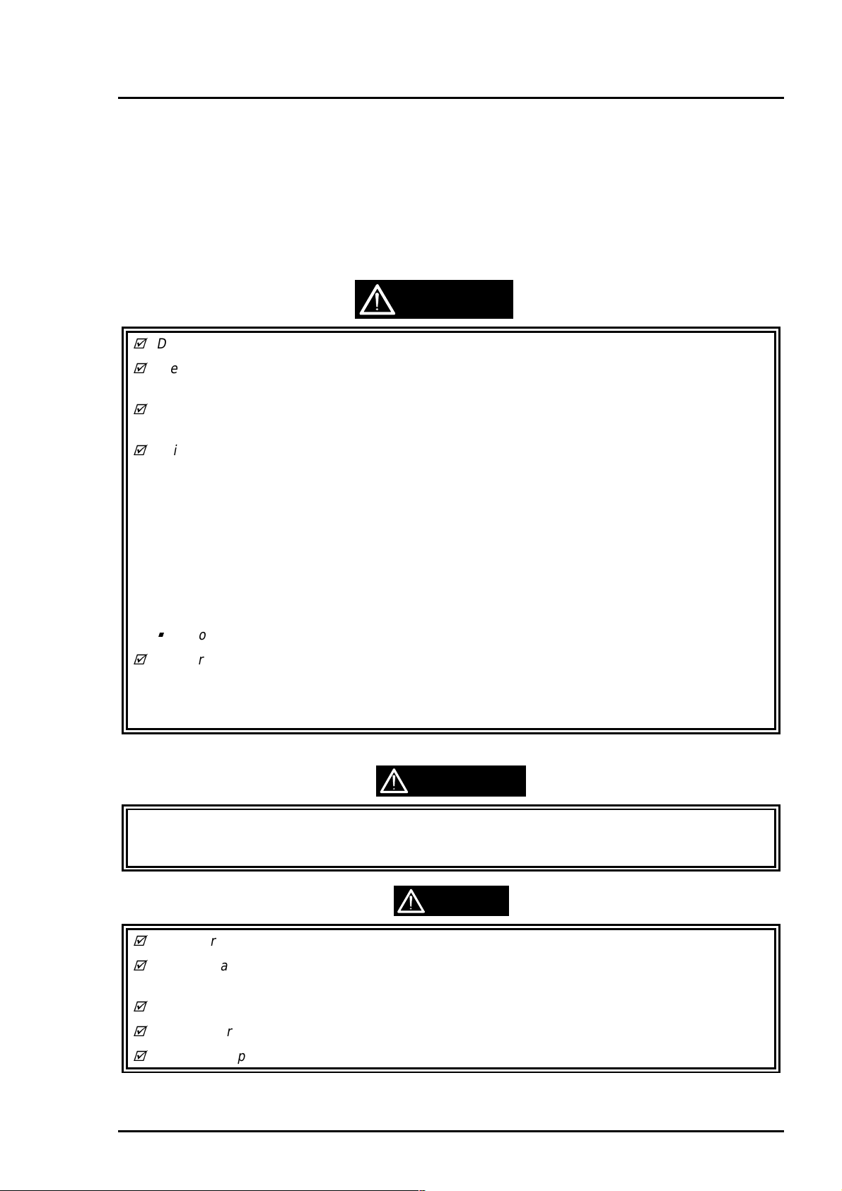
WARNING
Disconnect the power cable before disassembling or assembling the printer.
Wear protective goggles to protect your eyes from ink. If ink gets in your eye, flush the eye with
fresh water and see a doctor immediately.
If ink comes into contact with your skin, wash it off with soap and water. If irritation occurs,
contact a physician.
A lithium battery is installed on the main board of this printer. Be sure to observe the following
instructions when serving the battery:
• Keep the battery away from any metal or other batteries so that electrodes of the opposite
polarity do not come in contact with each other.
• Do not heat the battery or put it near fire.
• Do not solder on any part of the battery. (Doing so may result in leakage of electrolyte from the
battery, burning or explosion. The leakage may affect other devices close to the battery.)
• Do not charge the battery. (An explosion may be generated inside the battery, and cause burning
or explosion.)
• Do not dismantle the battery. (The gas inside the battery may hurt your throat. Leakage, burning
or explosion may also be resulted.)
Do not install the battery in the wrong direction. (This may cause burning or explosion.)
Danger of explosion if the battery is incorrectly replaced. Replace only with the same or equivalent
type recommended by the manufacture. Dispose the used batteries according to government’s
law and regulations.
Risque d’explosion si la pile est remplacée incorrectment. Ne remplacer que par une pile du même
type ou d’un type équivalent recommandé par le fabricant. Eliminer les piles déchargées selon les lois
et les règles de sécurité en vigueur.
CAUTION
Never remove the ink cartridge from the carriage unless manual specify to do so.
When transporting the printer after installing the ink cartridge, be sure to pack the printer for
transportation without removing the ink cartridge.
Use only recommended tools for disassembling, assembling or adjusting the printer.
Apply lubricants and adhesives as specified. (See Chapter 6 for details.)
Make the specified adjustments when you disassemble the printer. (See Chapter 4 for details.)
Rev. A
3-1
Page 3
EPSON Stylus Color 400 Service Manual
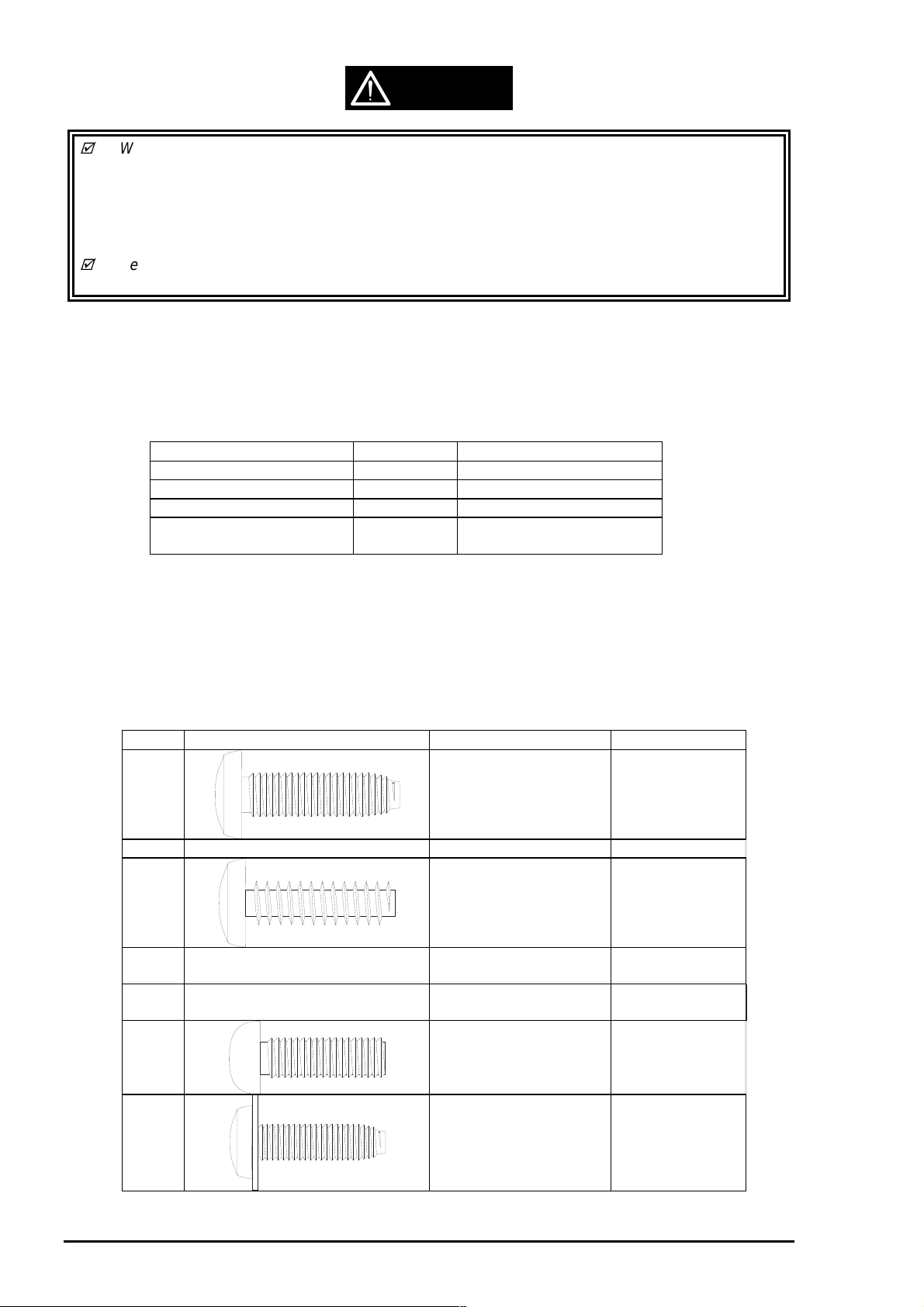
CAUTION
When assembling, if ink cartridge is removed and needs to be installed again, make sure to
install new ink cartridge because of following reasons;
Once the ink cartridge mounted on the printer is removed, air comes into and becomes bubbles
in the cartridge. These bubbles clog ink path and cause printing malfunction.
If an ink cartridge which are still in use is removed and is installed again, ink quantity will not be
detected correctly since the counter to check ink consumption is cleared.
Because of the reasons above, make sure to return the printer to the users with new ink
cartridge installed.
3.1.2 Tools
Table 3-1 lists the tools recommended for disassembling, assembling, or adjusting the printer.
Use only tools that meet these specifications.
Table 3-1. Recommended Tools
Tool Purchasable Code
Philips Screw Driver No.2
Philips Screw Driver No.1
Tweezers
Hexagon Box Driver
(Size:5.5mm)
Yes
Yes
Yes
Yes
B743800200
B743800400
B741000100
B741700100
3.1.3 Specification for Screws
Table 3-2 below shows specifications for screws. During assembly and disassembly, make sure the
locations for fixing screws and screw types, referring to the table below.
Also, described screw number in the text corresponds to the No. in the table.
Table 3-2. Screw Identification
No. Body Name Size
1 +Bind, S-tight M3X6
2 +Bind, S-tight M3X10
3 +Bind, P-tight
(CBP tight)
4 +Bind, P-tight
(CBP tight)
5 +Bind, P-tight
(CBP tight)
6 +Pan head
(CP)
M3X6
M3X10
M3X8
M3X4
3-2
7 +Bind, S-tight, Sems R2
(CBS Sems)
M3X6
Rev. A
Page 4
Chapter3 Disassembly and Assembly
3
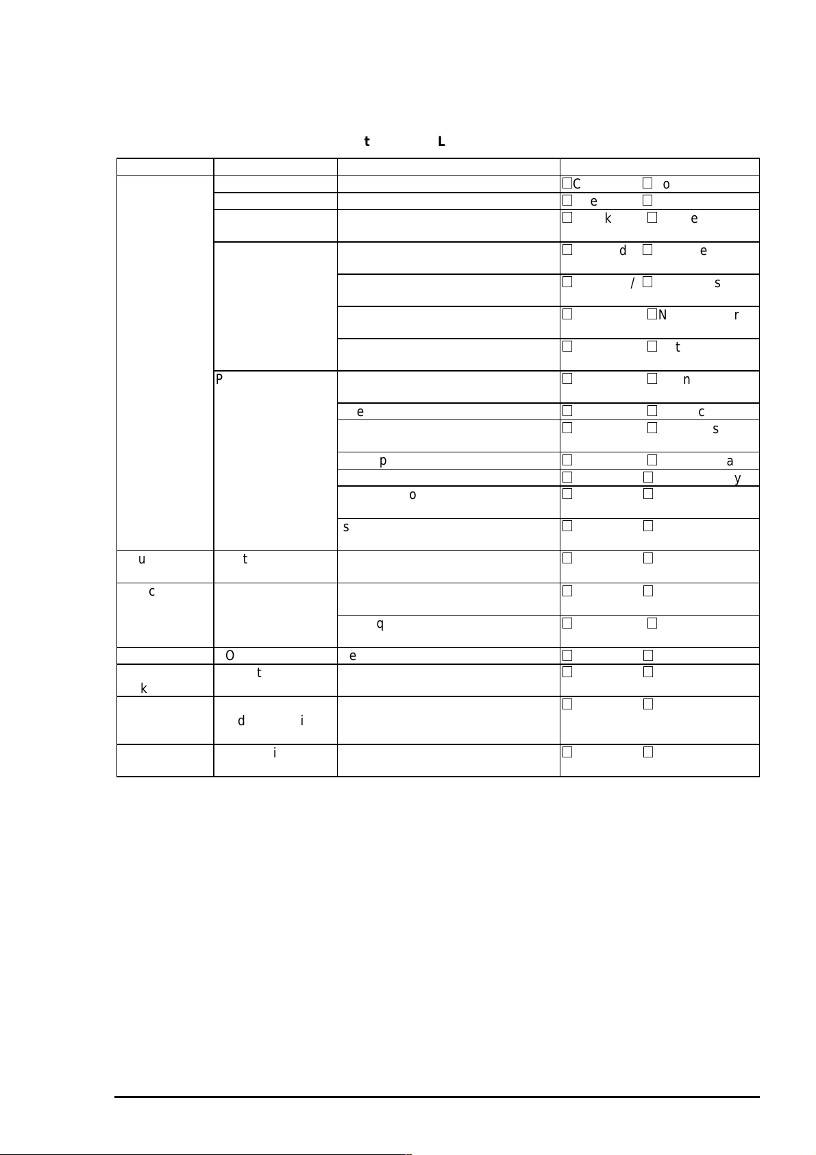
3.1.4 Service Checks After Repair
Before returning the printer after service, use the check list in Table 3-3, which provides a record to
make servicing and shipping more efficient.
Table 3-3. Inspection Check List for the Repaired Printer
Category Component Item to check Is Check required?
Self-test Is the operation normal?
On-line test Was the on-line test successful?
Print head Is ink ejected normally from the all
nozzles?
Carriage
mechanism
Printer units Is the CR motor at the correct
Paper feeding
mechanism
Adjustment Pointed adjustment
items
Lubricant Pointed lubricant
item
Function ROM version Newest version:
Shipment
package
Others Attached items Is all attached items from users
Ink cartridge Is the ink cartridge installed
Protection
conditions during
transport
Does the carriage move smoothly?
Any abnormal noise during
movement?
Any dirt or obstacles around the
axis of carriage guide?
temperature(not over heating)?
Is paper fed smoothly?
Does the paper get jammed?
Does the paper get skew during
paper feeding?
Are papers multi fed?
Does the PF motor get overheated?
Abnormal noise during paper
feeding?
Is the paper path clear of all
obstructions?
Are adjusted conditions all right?
Is lubrication applied to the pointed
locations?
Is the quantity of lubrication
adequate?
correctly?
Is all the pointed parts firmly fixed?
included?
Checked / Not necessary
Checked / Not necessary
Checked / Not necessary
Checked / Not necessary
Checked / Not necessary
Checked / Not necessary
Checked / Not necessary
Checked / Not necessary
Checked / Not necessary
Checked / Not necessary
Checked / Not necessary
Checked / Not necessary
Checked / Not necessary
Checked / Not necessary
Checked / Not necessary
Checked / Not necessary
Checked / Not necessary
Checked / Not necessary
Checked / Not necessary
Checked / Not necessary
Checked / Not necessary
Rev. A
3-
Page 5
EPSON Stylus Color 400 Service Manual
4
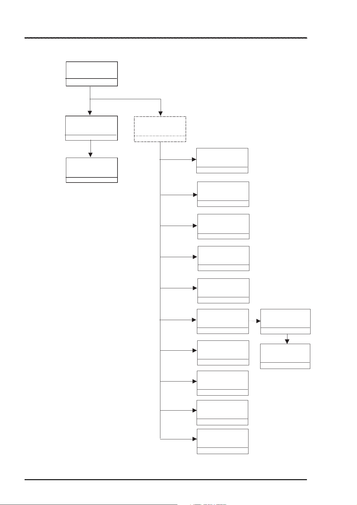
3.2 Disassembly Procedures
The figure below shows procedures for disassembly.
Remove
the Housing
Refer to
3.2.1
Remove
the Board Assembly
3.2.2
Remove the
operation panel
3.2.3
Remove the Printer
Mechanism
3.2.4
Remove
the Print Unit
3.2.4.1
Remove
the Absorber tray,
Assembly;A
3.2.4.2
Remove the Pump
Assembly,
Cap Assembly
3.2.4.3
Remove the CR
Motor Assembly
3.2.4.4.
Remove the PF
Motor Assembly
3.2.4.5
3-
Remove the ASF
Assembly
3.2.4.6
Remove the CR
Assembly
3.2.4.7
Remove the PF
Roller Assembly
3.2.4.8
Remove the PE
Paper Detector
Assembly
3.2.4.9
Remove the HP
Detector
3.2.4.10
Figure 3-1. Flow Chart of Disassembly
Remove the Paper
Feed Roller
Assembly
3.2.4.6.1
Remove the LD
Roller Assembly
(Right/Left)
3.2.4.6.2
Rev. A
Page 6
Chapter3 Disassembly and Assembly
5
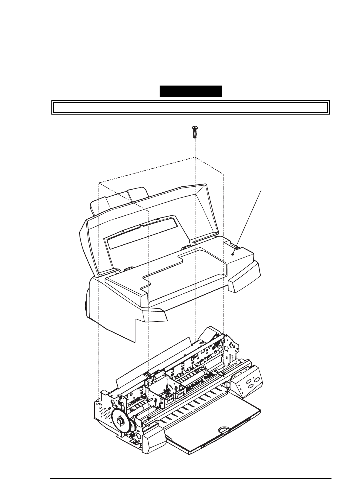
3.2.1 Removing the Housing
Since the printer mechanism itself structures the bottom part, the printer mechanism appears just by
removing the housing.
1. Open the printer cover and turn the PG adjustment lever towards (+) side.
2. Remove 4 screws(No.2) securing the housing, and remove the housing.
WORK POINT
Uplift and remove the housing, pulling it towards you.(Since it collides with carriage)
(No.2)
Housing
Figure 3-2. Removing the Housing
Rev. A
3-
Page 7
EPSON Stylus Color 400 Service Manual
6
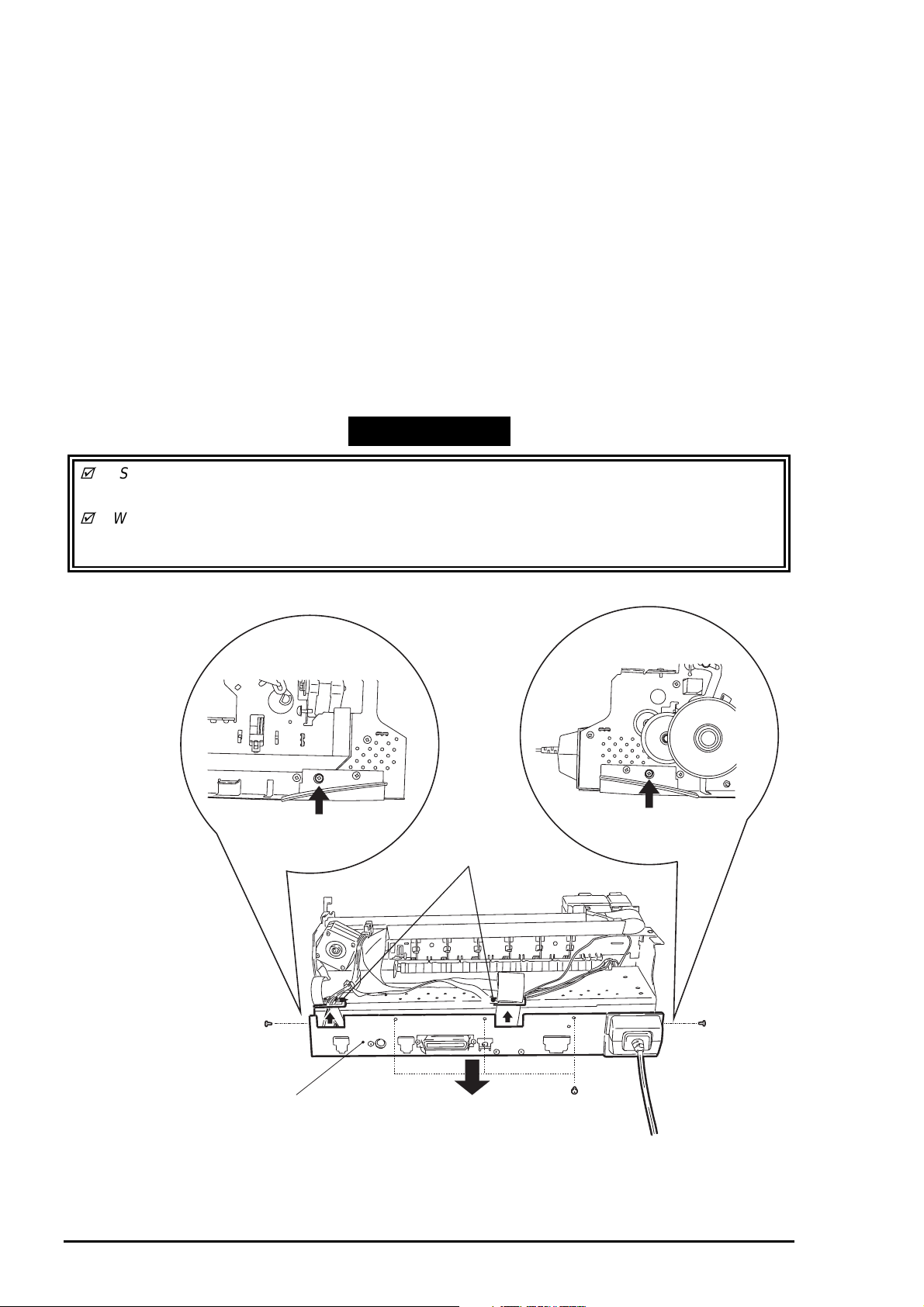
3.2.2 Removing the Board Assembly
Since the main board(C206 Main) and power supply circuit board(C206 PSB) are built in different
bracket from the printer mechanism, remove the whole bracket from the printer mechanism.
1. Remove the housing.(Refer to 3.2.2)
2. Remove the 5 screws(No.1) securing the “M/B Shield plate” on the printer mechanism.
3. Pull out the “M/B Shield Plate” a little bit and remove cables which are hung on the A and B holders
as you can see in the figure below.
Then, take all cables out of connectors on the C206 main board. (CN11 black, CN4 yellow, CN5 white,
CN3 black and CN8 FFC)
4. After removing all the cables from the C206 main board, detach the “Shield plate M/B” completely
from the printer mechanism.
5. When rem oving each board unit f rom the “M/B Shield plate”, r emove each sc rew securing each units
and shield plate. [C206 Main: 10screws (7 No.1 screws, 3 No.6 screws), C206 PSB/PSE:
4screws(No.1)] Refer to the next page for the figure.
Also, when removing the power supply board(C206 PSB), disconnect and also remove
the cable connecting to the Main board (CN6, 7 and 10 with lock device).
WORK POINT
Since connector CN 6,7 and 10 are the connector with lock dev ice, make sure to release the
lock before removing the cable. Also, make sure to lock when installing these cables.
When connecting cables to the connectors, each cable never cross each other in this printer.
So, if there are two connectors sitting next to each other, the cable from right should be connected
to the right connector and the cable from the left should be connected to the left one.
[Cable Holder A and B]
A
(No.1)
M/B Shield Plate
B
(No.1)
(No.1)
Figure 3-3. Removing the M/B Shield Plate
3-
Rev. A
Page 8
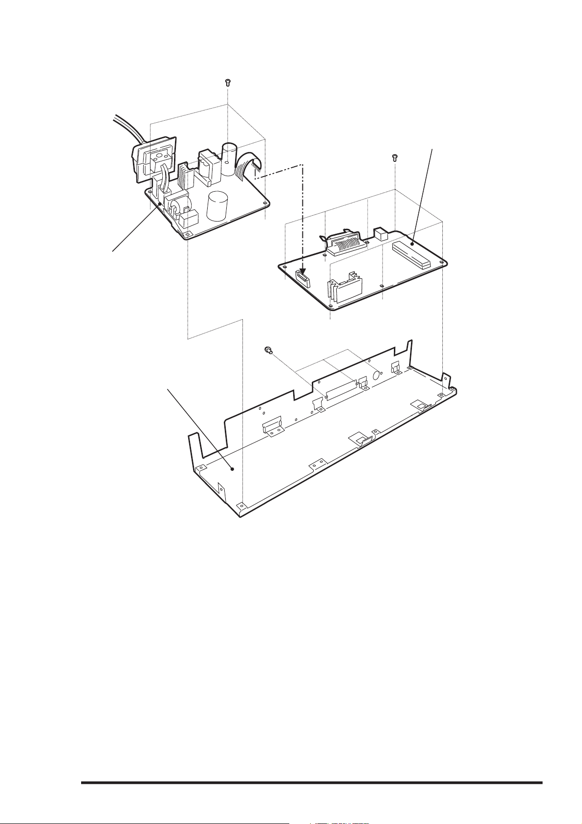
7
Power Supply Board
(C206 PSB)
(No.1)
Chapter3 Disassembly and Assembly
Main Board
(No.1)
(C206 Main)
M/B Shield plate
(No.6)
Figure 3-4. Removing the Boards
Rev. A
3-
Page 9
EPSON Stylus Color 400 Service Manual
8
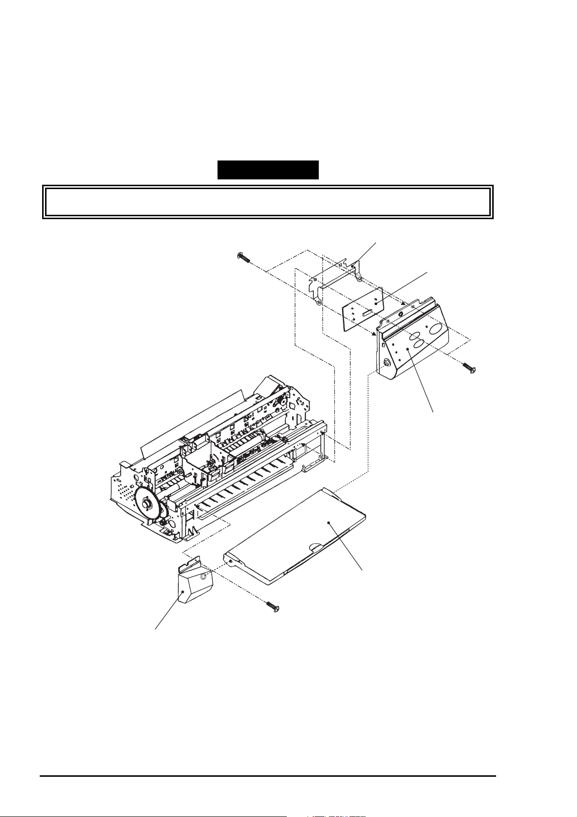
3.2.3 Removing the Operation Panel
1. Remove the housing. (Refer to 3.2.1)
2. Remove two screws (No.1) securing the operation panel and disconnect the operation panel from
the printer mechanism.
3. Remove one screw (No.1) and detach the left panel housing.
4. Remove two screws (No.3) securing the panel board assembly and take C206 PNL board out of
the panel assembly.
5. Disconnect the FFC from the connector on the C206 PNL board.
WORK POINT
Removing the operation panel also disconnects the stack er ass embly, since the operation panel holds
the stacker assembly.
Panel Shield Plate
(No.3)
Panel Board Assembly
(No.1)
Panel Assembly
Stacker Assembly
(No.1)
Left Panel Housing
Figure 3-5. Removing the Operation Panel
3-
Rev. A
Page 10

Chapter3 Disassembly and Assembly
9
3.2.4 Disassembling the Printer Mechanism
Since Stylus Color 400 does not have the lower housing, the printer mechanism part should be already
appeared by now. Therefore, this section explains procedures for disassembling the major parts or units
of printer mechanism.
3.2.4.1 Removing the Print Head Unit
1. Remove the housing. (Refer to 3.2.1)
2. Rotate the flat gear 67.2 towards yourself (front) and release the carriage lock mechanism.
Then move the carriage to the left edge.
3. Take both black and color ink cartridges out of the print head unit.
4. Remove the blue covers for black and color ink cartridge from the carriage assembly.
5. Remove the torsion spring 49 and one screw(No.3) and take the fastener head out.
6. Remove the FFC being placed on the carriage assembly, and take the print head unit
out of the carriage.
7. Disconnect the FFC from the connector on the drive board built in the print head unit.
WORK POINT
Make sure that earth board is installed to the carriage correctly. (There are 2 pins to determine
the location.)
When you built the print head into the carriage, make sure that a pin to determine the location on
the carriage side is put into the notch of the print head.
CAUTION
Since the ink cartridge once taken out can not be used again, be sure to install a new ink
cartridge when you return the printer to the user.
When you return the printer to the user, be sure to pack the printer for transportation with a new
ink cartridge installed and at the state that carriage is in the home position when the user turns
on the power.
REQUIRED ADJUSTMENT
When you replace the print head unit, perform the following adjustment. (Refer to Chapter 4 for
more details):
1) Initial ink charge (Refer to Chapter 4 /4.2.2.2)
2) Writing VH voltage ID (Refer to Chapter 4 /4.2.2.3)
3) Head Angle Adjustment (Chapter 4 /4.2.2.4)
Rev. A
3-
Page 11

EPSON Stylus Color 400 Service Manual
0
Print Head Unit
FFC
Fastener Head
Figure 3-6.Removing the Print Head
Make sure that this
protrusion is in the
U ditch of the priht head
side.
This part should
be touching the
CR axis receiver.
Make sure that protrusion
of carriage is in the hole
of the earth board.
Carriage Assembly
Print Head
Figure3-7.Installing the Print Head
3-1
Rev. A
Page 12

Chapter3 Disassembly and Assembly
3.2.4.2 Removing the Absorber Tray Assembly ;A
1. Remove the housing. (Refer to 3.2.1)
2. Remove the operation panel. (Refer to 3.2.3)
3. Remove one screw (No.4) securing “Absorber tray assembly” located on the right side of the printer
mechanism.
4. On the same right side of the printer mechanism, release the hook securing the absorber tray
assembly ;A on the frame and remove it, pulling it downward.
WORK POINT
When installing the absorber tray as s embly ;A, make s ur e to fix it with s pac er tr ay in the left s ide
of the printer mechanism.
(No.4)
Spacer Tray
Rev. A
Absorber Tray Assembly;A
Figure 3-8. Removing the Absorber Tray Assembly ;A
3-1 1
Page 13

EPSON Stylus Color 400 Service Manual
2
3.2.4.3 Removing the Pump Assembly and Cap Assembly
1. Remove the housing .(Refer to 3.2.1)
2. Remove the operation panel. (Refer to 3.2.3)
3. Remove the absorber tray assembly ;A. (Refer to 3.2.4.2)
4. Loose two screws located on the edges of the paper eject frame assembly and float the paper eject
assembly.
5. Rise the printer mechanism toward ASF side so that you can see the bottom of the printer
mechanism.
6. On the right side of frame, remove a hook holding the cap assembly and release two peaking
attached to the frame, uplifting the right side of cap assembly, then take it out towards the bottom
of the printer mechanism. However, the cap assembly is still connected to the pump assembly with
a ink tube at this point. (Refer to figures on the next page.)
7. Remove two screws(No.5) securing the pump assembly to the frame. (Refer to figures on the next
page.)
8. Release a hook securing the pump assembly to the frame and remove the pump assembly,
moving it toward right direction. (Refer to figures on the next page.)
CAUTION
Do not damage the rubber part (black square) of the cap installed in the cap assembly.(If it gets
damaged, it will not be able to attach closely with surface of the print head and may cause
malfunction of operation.)
When you deal with cleaner head built in the pump assembly for replacing, be careful about
following points.
• Do not touch the cleaner head with bare hands. Use gloves or tweezers.
• Do not let the cleaner head attach with oil or grease.
• When installing the cleaner head, the rubber side(darker black side) should be set toward on the
right side of the frame.
When installing the pump assembly, do not tighten the screw more than necessary torque.
WORK POINT
Since the spring is included in the combination of gears in the pump assembly, be careful not for
the parts being popped out during disassembly and assembly.
When assembling, be careful not to crush or leave any stress on the ink tube connecting
between pump assembly and cap assembly.
After installing the pump assembly, make sure that the cleaner parts can move front and back by
rotating the gear 67.2.
3-1
Rev. A
Page 14

3
Loosen screws on the right
and left sides and float the
Paper eject frame assembly.
Pump Assembly
Chapter3 Disassembly and Assembly
Release three hooks
from the interior of the
right frame assembly.
Cap Assembly
(No.5)
Figure 3-9. Removing the Cap and Pump Assemblies
Head Cleaner
Release a hook from the back
of the printer mechanism and
remove two protrusions from
the subframe.
Order of assembling
the pump parts.
Figure 3-10. Component of Pump Assembly
Rev. A
3-1
Page 15

EPSON Stylus Color 400 Service Manual
4
3.2.4.4 Removing the CR Motor Assembly
1. Remove the housing. (Refer to 3.2.1)
2. Rotate the gear 67.2 toward you and release the carriage lock mechanism. Move the carriage
to the center.
3. Loose the timing belt by pushing the driven pulley holder and remove the timing belt from the pulley
of the CR motor side.
4. Remove two screws(No.1) and take out the CR motor assembly.
WORK POINT
After installing the CR motor assembly, make sure that two peaking of motor bracket are in the holes
for determing position on the frame. (Refer to the figure on the next page)
Compression Spring 19.6
To the Exterior of Side Frame
Figure 3-1 1. Removing the Timing Belt
Driven Pulley Assembly
Timing Belt
To the Interior of Side Frame
Driven Pulley Holder
3-1
Rev. A
Page 16

Chapter3 Disassembly and Assembly
5
(No.1)
Make sure that protrusions of CR frame are in the holes
of the frame when installing the CR motor assembly.
Figure 3-12. Removing and Installing the CR Motor Assembly
Rev. A
3-1
Page 17

EPSON Stylus Color 400 Service Manual
6
3.2.4.5 Removing the PF Motor Assembly
1. Remove the housing.(Refer to 3.2.1)
2. Remove the absorber tray assembly ;A. (Refer to 3.2.4.2)
3. Remove the following gears located on the left side of the printer mechanism. Refer to the figure
below.
Gear 67.2 (Remove the ring with tweezers or (-) driver. After the ring is removed,
if you try to remove the gear 67.2 holding its edge, the gear may be broken. So, try
to remove it holding the whole gear, slightly pulling it toward you.)
Combination gear 8.8,21.6
Combination gear 8,14.4
Gear 36
4. Remove 3 hexagon nuts and take the PF motor assembly out.
WORK POINT
When disassembling the PF motor assembly, pull the motor assembly out of the frame a little bit
and remove it, sliding it into the bigger hole on the frame. (Refer to the figure next page)
Be careful for the direction of wires from the PF motor assembly.
Do not damage or leave any scars on the ditches of the gears during the disassembly and
assembly.
Compression Spring 0.9
Gear 67.2
C-Ring
Gear 34
Combination Gear8,14.4
PR Motor Assembly
Hexagon Nut
Gear 36
Combination Spring 8.8,21.6
Figure 3-13. Removing the PF Motor Assembly
3-1
Rev. A
Page 18

7
Direction of pulling
the motor lead cable.
Chapter3 Disassembly and Assembly
PF Motor(Back side of the
frame)
Set the pinion axis of PF motor
to the bigger hole once and slide
it to the smaller hole.
Figure 3-14. Installing the PF Motor Assembly
Rev. A
3-1
Page 19

EPSON Stylus Color 400 Service Manual
8
3.2.4.6 Removing the ASF Assembly
1. Remove the housing. (Refer to 3.2.1)
2. Release the fixed hook from the inside of printer mechanism and remove the gear 34 from the roller
axis of the ASF assembly.
3. Take out cables from the cable hook on the printer mechanism and from the hook of the ASF
assembly.
4. After removing 2 screws(one No.7 and one CR axis installation screw), remove the ASF assembly,
detaching peaking on the left side of ASF assembly from the frame holes.
WORK POINT
When installing the ASF assembly, make sure that the frame and ASF assembly are attached
each other without any space.
Screws for ASF assembly should be used at the following positions. (Looking from the back of
printer)
Right :CR axis installation screw
Left : Screw No.7 (•{Bind, S- tight, Sems R2; with plane washers)
CR Axis Installation Screw
Screw with Washer (No.7)
Gear 34
Make sure that protrusions
in the ASF Assembly are in
these holes on the frame
when installing the ASF
assembly.
Figure 3-15.Removing the ASF Assembly
3-1
Rev. A
Page 20

Chapter3 Disassembly and Assembly
9
3.2.4.6.1 Removing the Paper Feed Roller Assembly
1. Remove the ASF assembly. (Refer to 3.2.4.6)
2. Remove the brake lever, releasing one leg of the torsion spring 41.2 from the hook of the ASF frame.
3. Remove the fixing axis bush from the right side of LD the roller axis and hopper lever release.
4. Move the left side of paper feed assembly part to the center and remove the cam fixed bush (white
plastic) attached to the left side of LD roller axis.
5. Push the LD roller axis to the left and remove the left axis fixed bush after releasing its hook.
6. Remove right and left sides of hopper assembly from the peaking of the ASF frame.
7. Uplifting the right side of paper feed roller assembly a little bit, push the LD roller axis to the right
and remove it from the left side of the ASF frame.
8. Holding the hopper assembly by hand, remove the cam part of hopper assem bly from the right holes
of ASF frame.
The procedures by here should disassemble right and left roller assembly and hopper assembly.
WORK POINT
During disassembly and assembly of the hopper as sembly, do not let the grease on the cam
parts attach to the other parts. Wipe it if grease attached to the other parts.
Be careful for the direction of the hopper lever release, when installing it.
Make sure that right and left fixed bushes are installed steadily and do not slip off.
During assembly, attach the cam fixing bush after installing CD roller-axis to the ASF frame.
When installing right and left paper feed roller assemblies to the LD roller ax is, a black paper
feed roller assembly comes to right side and the EPSON standard color one comes to left on
the axis.
Hopper Assembly
Brake Lever
Torsion Spring 41.2
ASF Frame
Left Fixing Axis Bush
Release Hopper Lever
(EPSON standard
color)
(Black)
Paper Feed Roller Assembly
LD Roller Axis
Fixing Axis Bush
Figure 3-16. Disassembly of ASF Assembly
Rev. A
3-1
Page 21

EPSON Stylus Color 400 Service Manual
0
3.2.4.6.2 Removing the Right and Left LD Roller Assembly
1. Disassemble the ASF assembly and remove the paper feed roller assembly and hopper
assembly from the ASF body. (Refer to 3.2.4.6)
2. Take out right and left compression springs 1.66 from the back of hopper assembly.
3. Pull out the cam part of the hopper assembly from the frame hole located on the right side of paper
feed roller assembly.
4. Pull out the LD roller axis.
The paper feed roller assembly and hopper assembly should be disconnected by now.
5. Release the hook of LD roller assembly at the axis hole of the paper feed roller assembly.
Also, release the fixed hook of cover roller LD and remove the LD roller assembly.
WORK POINT
When installing the LD roller assembly, make sure that the hooks are hung on the paper feed
assembly.
During assembly, when setting the compression spring 1.66 to the spring installation position in
the paper feed assembly, hang the spring on the hook temporarily. Also, do not forget to release
the hooks of these springs from the holes located on the back of paper feed assembly by
rotating the spring. (Refer to the figure below.)
LD Roller Assembly
(Right and Left)
Paper Feed Assembly
(Right and Left)
LD Roller Cover
(Right and Left)
+
Paper Feed Holder Sheet
Compression Spring 1.66
During assembly, set the
compression spring 1.66 in
the position for spring installation
of the paper feed assembly and hang
the bent part of the spring on the hook.
Figure 3-17. Disassembly of Paper Feed Roller Assembly
3-2
Rev. A
Page 22

Chapter3 Disassembly and Assembly
3.2.4.7 Removing the Carriage Assembly
1. Remove the housing. (Refer to 3.2.1)
2. Loose the timing belt by pushing the driven pulley holder and remove the timing belt from the pulley
of the CR motor side.
3. Take the compression spring 19.6 out of the driven pulley holder.
4. Remove the driven pulley assembly from the driven pulley holder with the timing belt. Slide the
driven pulley holder and remove it from the frame.
5. Remove the torsion spring hanging on the frame and PG lever. Release the fixed hook of the PG lever
and remove the lever.
6. Release the fixed hook of the PG lever support and remove the PG lever support and washer from
the edge of CR guide axis. (Refer to the figure next page.)
7. Remove one screw(No.7) and rotate the right parallelism adjustment bush so that it fits to the notch
of the frame, and remove it .
8. Remove CR assembly with CR guide axis.
WORK POINT
When disassembling the parallelism adjustment right bush, mark present fixed location of the
bush on the frame so that you can omit re-adjustment of gap when assembling.
When installing the washer, pay attention to its direction.(Convex side should face to the right
parallelism adjustment bush side.) Refer to the figure below.
When installing the PG lever, refer to the figure below.
Insert this side to the
hole on the right frame.
To the PG Lever
Torsion Spring 63.7
Figure 3-18. Installing the PG Lever
Elliptic Holes
PG Lever
PG Support Lever
Rev. A
3-21
Page 23

EPSON Stylus Color 400 Service Manual
2
Left Parallelism
Adjustment Bush
Carriage Assembly
CR Guide Axis
Washer
[Convex side should face
to the bush side, during installation]
Figure 3-19. Removing the Carriage Assembly
Right Parallelism Adjustment Bush
PG Support Lever
3-2
Rev. A
Page 24

Chapter3 Disassembly and Assembly
3
3.2.4.8 Removing the PF Roller Assembly
1. Remove the housing.(Refer to 3.2.1)
2. Remove the carriage assembly.(Refer to 3.2.4.7)
3. Remove two screws(No.1) on the printer mechanism and disassemble the cable guide board.
4. Remove six upper paper guide assemblies, releasing their springs from the hooks of the frame.
5. Remove the front paper guide ;B, releasing the hooks. (Refer to next page)
6. Remove the paper eject roller assembly, releasing the fixed locks located on the right and left
edge of axis.
7. Release the fixed hook located on the left side of PF roller assembly axis and rotate it so that
protrusion of axis(white) and hole for receiving the frame axis can match.
8. Slide the PF roller assembly to the right direction and pull it out.
WORK POINT
During disassembly and assembly of upper paper guide assemblies, since one of the upper
paper guide assemblies to be installed on the right side overlaps with the PE detector lever, pay
attention not to damage the lever.
Be careful not to damage the hook, during the disassembly and assembly of the front paper
guide ;B.
Be careful not to scar the PF roller assembly during the disassembly and assembly, since its
surface is specially coated to improve paper feeding. (black part)
Be careful not to damage the combination of gears.
Left Paper Guide
(No.1)
Cable Guide Board
Upper Paper Guide
Assembly
(6 positions)
Upper Paper Guide Axis
Torsion Spring 117.6
Figure 3-20. Removing the Paper Guide Assembly
Rev. A
3-2
Page 25

EPSON Stylus Color 400 Service Manual
4
Eject Paper Roller
Assembly
Front Paper Guide;B
Figure 3-21. Removing the Paper Eject Roller Assembly
Match the protrusion of PF roller
assembly and hole of the frame for
holding the axis.
PF Roller Assembly
Figure 3-22. Removing the PF Roller Assembly
3-2
Rev. A
Page 26

Chapter3 Disassembly and Assembly
5
3.2.4.9 Removing the PE Paper Detector Assembly
1. Remove the housing.(Refer to 3.2.1)
2. Release two fixed hooks securing the PE detector assembly from the back of frame and remove the
PE detector assembly, sliding it upward. Remove PE board assembly and PE lever if necessary.
WORK POINT
During assembly, make sure that the tip(sensor part) of the detec tor lever is in the hole of paper guide
assembly.
After releasing two hooks, remove
the PE paper detector assembly,
sliding it upward.
(From back side of the frame)
PE Holder
This side should be
installed on the frame.
PE Board Assembly
Figure 3-23. Removing the PE Paper Detector Assembly
PE Lever
Torsion Spring 0.22
Rev. A
3-2
Page 27

EPSON Stylus Color 400 Service Manual
6
3.2.4.10 Removing the HP Detector
1. Remove the housing. (Refer to 3.2.1)
2. Remove the cable from the HP detector and take it out after releasing the fixed hook.
HP Detector
3-2
Figure 3-24. Removing the HP Detector
Rev. A
 Loading...