

Page 1

Chapter 4
Adjustment
4.1 Overview................................................................................................................4-1
4.1.1 Required Adjustments ........................................................................................................... 4-1
4.1.2 Required Adjustment Tools................................................................................................... 4-1
4.2 Adjustment............................................................................................................4-2
4.2.1 Parallel Adjustment................................................................................................................4-2
4.2.2 Adjustment by Adjustment Program .................................................................................... 4-4
4.2.2.1 Specification of Adjustment Program........................................................................ 4-4
4.2.2.2 Initial Ink Charge Operation....................................................................................... 4-5
4.2.2.3 VH Voltage Writing Operation ................................................................................... 4-6
4.2.2.4 Print Head Angle Adjustment .................................................................................... 4-7
4.2.2.5 Bi-D Adjustment ........................................................................................................ 4-9
Page 2
Chapter4 Adjustment
4.1 Overview
This section describes adjustments required when the printer is disassembled and assembled after repair.
4.1.1 Required Adjustments
Stylus Color 400 has following required adjustments.(Refer to table 4-1) Refer to figures for the actual
procedure and perform appropriate adjustment for each exchanged unit.
Table 4-1. Required Adjustment and Contents
No. Adjustment Item Conditions
1 Parallel Adjustment • When you exchange or remove the Carriage guide shaft.
• When you move the parallelism adjustment bush.
2 Initial ink charge • When you exchange or remove the print head.
3 VH voltage Writing Operation • When you exchange or remove the print head.
• When you exchange the C206 main board.
Note)
The values of address are not lost by EEPROM reset
operation.
4 Printing Head Angle Adjustment • When you exchange or remove the print head.
• When you move the head adjustment lever.
5 Bi-D adjustment • When you exchange or remove the print head.
• When you exchange the C206 main board.
Table 4-2. Operation and Adjustment Item
No. Content of Operation Adjustment Procedure
1 Exchange or Removal of Print head 1)Perform Vh voltage writing operation.
(Only when the print head is exchanged)
2)Perform initial ink charge.
3)Perform print head angle adjustment.
4)Perform Bi- d Adjustment.
2 Exchange of C206 Main Board 1)Perform Vh voltage writing operation.
2)Perform Bi-d adjustment.
3 Exchange or Removal of Carriage Unit 1)Perform parallel adjustment.
2)Perform print head angle adjustment.
3)Perform Bi-d adjustment.
4 Exchange of CR Motor 1)Perform Bi-d adjustment.
5 Exchange of Printer Mechanism 1)Perform Vh voltage writing operation.
2)Perform initial ink charge.
3)Perform Bi-d adjustment.
4.1.2 Required Adjustment Tools
The table4-3 below shows adjustment tools for Stylus Color 400.
Table 4-3. Adjustment Tools for Stylus Color 400
No. Name Adjustment item Content/Specification
1 Thickness Gage Parallel Adjustment Thickness=1.1mm(1.04mm)
2 Adjustment Program Each Mechanism Settings Exclusive Program(“J80C10E”)
Rev. A
CAUTION
Never use the bent (curved or tilted)or rusty thickness gage.
Erase any dirt, grease or obstacles on the thickness gage before you use it.
4-1
Page 3
EPSON Stylus Color 400 Service Manual
2
4.2 Adjustment
This section explains specific procedures for each adjustment required for Stylus Color 400.
4.2.1 Parallel Adjustment
When exchanging carriage assembly and or removing it along with disassembly of printer mechanism,
perform parallel adjustment when assembling and set the standard distance from the surface of the print
head to the paper surface.
CAUTION
Do not scar the special coated surface of the PF roller assembly(platen) and lib surface of the
front paper guide ;B.
Be careful not to leave any scars or dirt on the surface of the print head.
(Never use the rusty or dirty thickness gage. Also, do not push hard the thickness gage to the
head.)
[Right Parallelism Adjustment]
1. Install the “parallelism adjustment bush” for right and left frame and set them on the peaking of the
upper frame side so that they match with “the standard mark of parallelism adjustment bush”.
2. Set the PG lever front. (Gap is small.)
3. Move the carriage to the center and set the thickness gage on the fixed position of front paper
guide ;B as you can see in the figure 4-1 on the next page
4. Move the carriage to the position that the print head overlaps the thickness gage.
WORK POINT
Put the thickness gage on the flat side of the lib of the front paper guide ;B.
When you move the carriage, move it, pulling the timing belt with your hand.
5. Move the right parallelism adjustment to the rear direction until the thickness gage moves with the
carriage when you move the carriage 20mm back and forth in right and left direction.
(Gap will be narrowed.)
6. From the state of the thickness gage moves with carriage movement, move the gear for locating the
position of the right parallelism adjustment bush one serration toward you.(Gap will be widen.
7. In the state that PG lever is set front(gap is small) and rear side respectively, move the carriage
right and left and make sure that the thickness gage does not move at this time.
[Left Parallelism Adjustment]
8. Perform above procedures from 2 to 7 for left parallelism adjustment bush.
[Checking parallelism]
9. Perform procedures from1 to 4 again.
10. Make sure that the thickness gage does not move along with carriage movement when the carriage
is moved 20mm back and forth.
11. In the state that the right parallelism adjustment bush is moved one serration toward rear(Gap will be
narrowed),make sure that the thickness gage moves along with carriage movement.
If the thickness gage does not move, perform procedures from 1 again.
12. Move the right parallelism adjustment bush one serration toward you(Gap will be widen).
[Fixing Parallelism Adjustment Bush]
13. Fix the right and left parallelism adjustment bushes by screws.(No.1 screw each for right and left.)
When completing this adjustment, check the overlap amount of print head and head cleaner.
1. Rotate the gear 67.2 and move the head cleaner to the print rear side.
2. Move the carriage next to the head cleaner and make sure that overlap between the tip of the print
head and cleaner head is more than 0.5mm.
3. After that, rotate the gear 67.2 and return the head cleaner to the front position.
4-
Rev. A
Page 4
Chapter4 Adjustment
3
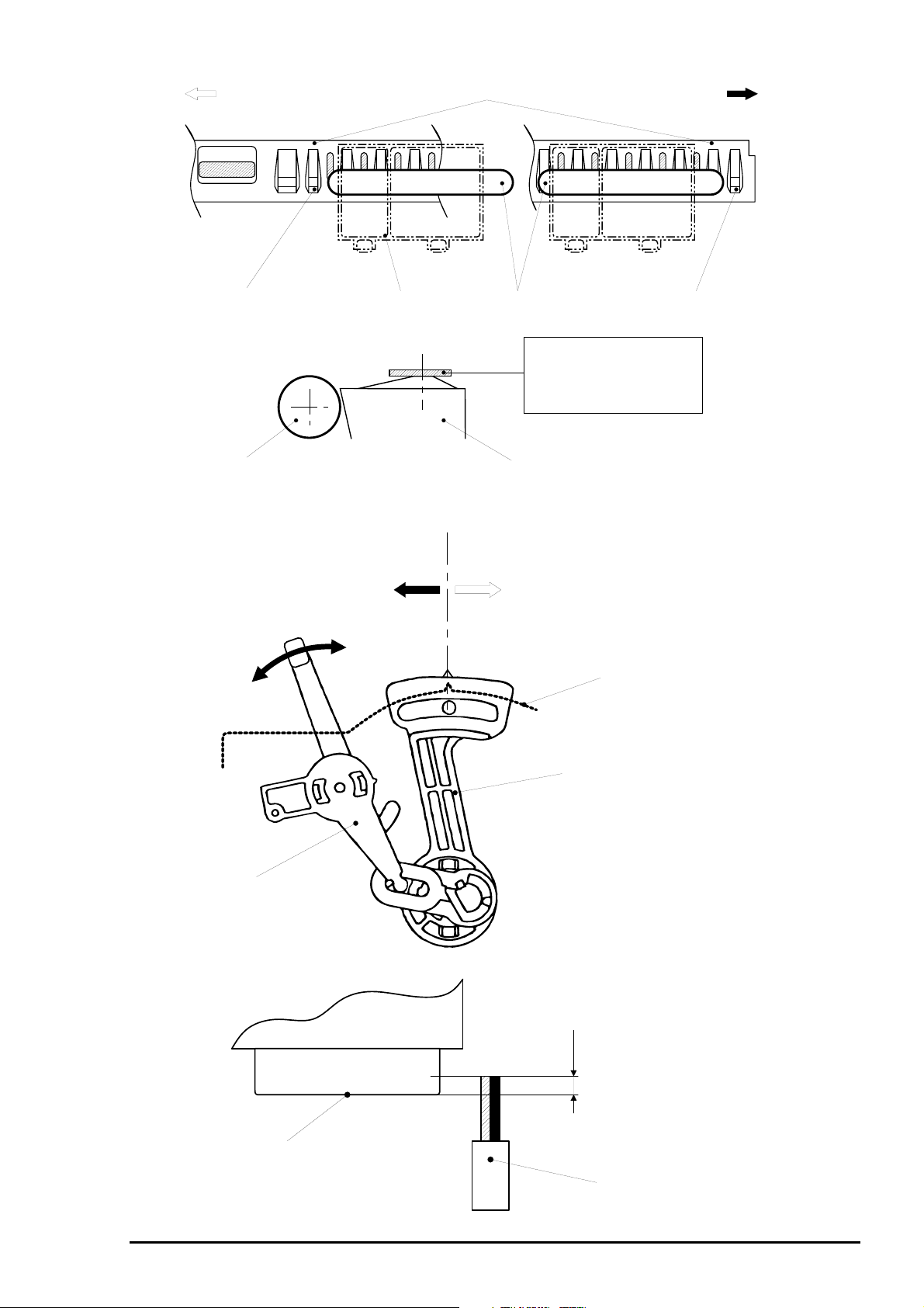
Left Side
Lib;Avoid 2 libs from left edge
PF Roller Assembly
Figure 4-1. Setting of the Gage at Parallel Adjustment
Front Paper Guide;B
Carriage
Thickness Gage
Front Paper Guide;B
Standard Position Mark
Lib; Avoid 2 libs from right edge
Put the thickness gage flat
on the flat side of lib.
Also, match the center of
the thickness gage and
flat side of the lib.
Right Side
(0)
PG Lever
Front
(Gap will be widened)
(+)
Figure 4-2. Parallel Adjustment
Rear
(Gap will be narrowed)
Frame
Parallelism Adjustment Bush
Overlap amount
= More than 0.5mm
Print Head Side
Cleaner Head
Figure 4-3. Overlap of Head Surface and Cleaner Brade
Rev. A
4-
Page 5

EPSON Stylus Color 400 Service Manual
4
4.2.2 Adjustment by Adjustment Program
In this printer, it is necessary to set correct information for each printer mechanism in order to maintain
homogeneous printing function and quality, erasing dispersion of each printer mechanism’s
characteristics.
Therefore, in case that the combination of printer mechanism and main board is changed or the print head
is exchanged by repair service, it is required to set and register correct information in the main board,
using the exclusive adjustment program.
4.2.2.1 Specification of Adjustment Program
Adjustment Program (Program name:”J80C10E”) is to set various correct values in order to prevent
development of malfunction and fluctuation of printing quality and printing function by dispersion of
components and assembly when the printer components are exchanged during the repair service.
Basic adjustment procedure by using this program are following.
Main Menu
(Item Selection)
Initial Ink Charge
Performance of Initial
ink charge process
Head VH voltage
ID writing.
Input of appointed
VH voltge ID
Head Angle
Adjustment
*Pattern printing
*Confirmation/
Mechanism
Adjustment
Figure 4-4. Flow of Adjustment Program
Bi-D Adjustment
*Pattern printing
*Confirmation/
Input of correct
values
4-
Rev. A
Page 6

Chapter4 Adjustment
5
4.2.2.2 Initial Ink Charge Operation
There is no ink charged in the ink path of the print head that is mounted on the print head and printer
mechanism as spare parts. Therefore, when the following units are exchanged, perform initial ink
charge and return the printers after making sure that ink is discharged correctly from the print head.
When exchanging the printer mechanism
When exchanging the print head
When exchanging the C206 main board (Refer to “Caution” below.)
CAUTION
Before or after performing this operation, perform appropriate adjustment or operation, referring
to the table 4-2.
Since this operation consumes quite amount of ink, do not perform more than necessary except
for ink absorption for the recovery from nozzl e clogging and exchange of C206 main board.
Note)
Refer to the end of this chapter for [Screen 1 to 6] when you perform procedures below.
1. Connect the printer and PC and turn on the printer. Install the newly just opened black and color ink
cartridge. (When C206 main board is exchanged, it is not necessary to perform initial ink charge
by the program since initial ink charge is performed automatically at this point.)
2. Insert the disk of adjustment program to the floppy disk drive of PC. Type Load”
press the return key.
3. After running the adjustment program, press the return key on the menu [Screen-1] indicated
on the PC screen. Then, press the return key again on the [Screen-2].
4. Select “1”(WORLD) on the [Screen-3].
5. Input “2” (Cartridge) on the ink supply method selection screen [Screen-4] and press the return key.
Note)
Do not press “1”(Jig) at this point, because it consumes ink more than necessary.
6. Initial menu screen [Screen-5] appears. At this point, select “1”(Production).
7. On the main screen [Screen-6], select “2”(Ink Charge). After this, initial ink charge is performed
automatically.
a:\J80C10E
and
CAUTION
Since [Screen-1] through [Screen-6] are attached in the end of this chapter, refer to them for
procedures above.
Rev. A
4-
Page 7

EPSON Stylus Color 400 Service Manual
6
4.2.2.3 VH Voltage Writing Operation
There are dispersion in the PZT which are used for print head. It is necessary to set available and
appropriate printing by registering mean values(VH voltage) of these PZT dispersion in the EEPROM.
Therefore, when the next operations are done, it is necessary to confirm VH voltage ID and to register
to EEPROM on the main board by the program.
When exchanging the print head
When exchanging the printer mechanism
When exchanging the C206 main board
CAUTION
Before or after performing this operation, refer to the table 4-2 and perform appropriate
adjustments or operations.
1. When exchanging parts above, make a note of VH voltage ID that is appointed in advance.
Indication position of the Print head : VH voltage ID is stamped on the side face
of the print head.
Indication position of the printer mechanism : VH voltage ID is written on the label of the
packing box of the printer.
2. Connect the printer and PC and turn on the printer. Install the newly just opened black and color link
cartridge. (If C206 main board is exchanged, initial ink charge is performed automatically.)
3. Insert the disk of adjustment program to the floppy disk drive of PC. Type Load”
press the return key.
4. After running the adjustment program, press the return key on the menu [Screen-1] indicated
on the PC screen. Then, press the return key again on the [Screen-2].
5. Select “1”(WORLD) on the Customer [Screen-3].
6. Input “2” (Cartridge) on the ink supply method selection screen, [Screen-4] and press the return key.
Note)
Do not press “1”(Jig) at this point, because it consumes ink more than necessary.
7. Initial menu screen [Screen-5] appears. At this point, select “1”(Production).
8. On the main screen [Screen-6], select “1”(VH setting). Input “0” in the M/C No. of the [Screen-7]
and press the return key.
9. Input VH(3-code) that you made a note of VH voltage ID to the [Screen-8]. If you input wrong, press
the space key and restart from procedure 7. After checking if correct selection is made, press the
return key and return the screen to the main menu [Screen-6]. At this time, printer mechanism
performs initialization.
10. When you perform only VH voltage input, turn the power off after completing initialization and
register input value to the EEPROM. If you want to continue adjustments such as angular adjustment
or Bi-d adjustment, using this program, perform the next adjustment on the main menu screen
[Screen-6] without turning power off here.
a:\J80C10E
and
CAUTION
Since [Screen-1] through [Screen-6] are attached in the end of this chapter, refer to them for
procedures above.
4-
Rev. A
Page 8

Chapter4 Adjustment
7
4.2.2.4 Print Head Angle Adjustment
The dispersion of print head and carriage that is the base of installing the print head are caused
during the production and gives bad influences on the angle of the print head. If the angle of the print
head is not correct, overlap of colors is not performed correctly. This results in causing color lines or white
lines. In order to prevent this, an exclusive lever to adjust the print head angle is installed in the side face
of the carriage unit. This makes it possible to adjust the head angle without removing the ink cartridge.
It is required to perform this adjustment at the following cases.
When exchanging the print head
When exchanging the carriage unit
When moving the angle adjustment lever
Since the position for installing the print head is determined by the adjustment lever built in the carriage
unit, this adjustment determines the position for installing the print head by the adjustment lever on
the carriage unit according to the result of printing of the check patter to check the angle degree by
the adjustment program.
CAUTION
Before or after performing this operation, refer to the table 4-2 and perform appropriate
adjustments or operations.
1. Connect the printer and PC and turn on the printer. Install the newly just opened black and color link
cartridge. (If C206 main board is exchanged, initial ink charge is performed automatically.)
2. Insert the disk of adjustment program to the floppy disk drive of PC. Type Load”
press the return key.
3. After running the adjustment program, press the return key on the [Screen-1] of the menu indicated
on the PC screen. Then, press the return key again on the [Screen-2].
4. Select “1”(WORLD) on the Customer [Screen-3].
5. Input “2” (Cartridge) on the ink supply method selection screen, [Screen-4] and press the return key.
Note)
Do not press “1”(Jig) at this point, because it consumes ink more than necessary.
6. Initial menu screen [Screen-5] appears. At this point, select “1”(Production).
7. On the main screen[Screen-6], select “3”(Angular Adjust Print). At this time, the printer prints pattern
automatically for checking the head angle. From the top, the printer prints in black•¨YMC•¨
black/magenta. After checking this print result, if the pattern is printed normally, following steps are
not necessary.
8. If more adjustment is necessary, select “K”(Angular Adjust Setting) on the main screen [Screen-6].
By performing this, since the carriage moves to the central position even if the upper case is
attached, the adjust lever can be reached easily.
9. Refer to the next page.
a:\J80C10E
and
CAUTION
Since [Screen-1] through [Screen-6] are attached in the end of this chapter, refer to them for
procedures above.
Rev. A
4-
Page 9

EPSON Stylus Color 400 Service Manual
8
9. Loosen a screw securing the print head on the carriage.
(It is not necessary to remove it completely: Refer to the figure below.)
Print Head
Screw
Figure 4-5. Position of the Print Head
CAUTION
Make sure to loosen the screw. If the screw is not loose, the print head angle can not be
changed even if the position of the adjust lever is moved.
10. Pay attention to the combination pattern of black/magenta and change the position of the adjust lever
so that a magenta line comes to between above and below black lines, adjusting the print
head angle by the adjust lever. The figure 4-6 below shows changes of actual printing pattern of
black/magenta combination with the operation of the adjust lever.
Black Line
Printing Result
Magenta Line
Direction of Adjustment:
Move the lever
to the right(rear).
Direction of Adjustment:
Move the lever
to the left(front).
Adjust Lever
(Right rear of the
carriage)
Figure 4-6. Adjustment of Combination Pattern of Black and Magenta
11. After changing the position of the adjust lever, press “Y” key and return the carriage to the
home position.
12. Check again the combination pattern of black/magenta after changing the position of the adjust lever.
13. Repeat the procedures from 7 to12 until the combination pattern of black/magenta comes to
proper position.
14. After completing adjustment, select “K” (Angular Adjust Setting) on the main screen [Screen-6] and
tighten the loosen screw steadily.
4-
Rev. A
Page 10

Chapter4 Adjustment
9
4.2.2.5 Bi-D Adjustment
This adjustment is to correct dispersion of printing positions caused by slippage of printing timing in right
and left direction during the bi-directional printing. Therefore, it is required to perform this adjustment
if the following operations are performed.
1)When exchanging the Print mechanism 2)When exchanging the C206 main board
3)When exchanging the CR motor 4)When exchanging the Carriage
5)When exchanging the Assembly 5)When exchanging the Print Head
The values which are set in this adjustm ent are registered in the EEPROM of the m ain board as cor rect
values of print timing in the right and left direction.
CAUTION
Before performing this operation, refer to the table 4-2 and perform appropriate adjustments or
operations.
1. Connect the printer and PC and turn on the printer. Install the newly opened black and color link
cartridge. (If C206 main board is exchanged, initial ink charge is performed automatically.)
2. Insert the disk of adjustment program to the floppy disk drive of PC. Type Load”
press the return key.
3. After running the adjustment program, press the return key on the [Screen-1] of the menu indicated
on the PC screen. Then, press the return key again on the [Screen-2].
4. Select “1”(WORLD) on the Customer [Screen-3].
5. Input “2” (Cartridge) on the ink supply method selection screen, [Screen-4] and press the return key.
Note)
Do not press “1”(Jig) at this point, because it consumes ink more than necessary.
6. Initial menu screen [Screen-5] appears. At this point, select “1”(Production).
7. On the main screen [Screen-6], select “4”(Bi-D Adjust). After this, three Bi-D patterns are printed
automatically back and forth, as centering the presently set center value.
8. Check the Bi-D pattern and find out that the value should be adjusted to (+) side or (-) side.
Note)
At this time, if the predicted value is quite different, comparing the present center value,
change the center value by the following procedures.
a:\J80C10E
and
[Step8-1] On the [Screen-7], input “Y” once and return to the main screen [Screen-6].
At this time, the presently fed paper is once ejected.
[Step8-2] On the main screen, the screen goes back to initial menu [Screen-5] by inputting
“E” key and pressing the return key.
[Step8-3] On the screen, input “6”(Bi-D Center) and press the return key.
[Step8-4] Since the screen asks you New Bi-D Center, input a now value and press the
return key. The screen goes back to the initial menu screen [Screen-5] and make
sure that the new value that you input is in the “6” of the Bi-D Center.
9. Determine a value as goal and input random value on the [Screen-7]. The Bi-D pattern will be printed
again by pressing the return key.
If proper lines are found among the three patterns, input that value again on the [Screen-7] and
press the return key. For confirmation, only the pattern by selected value will be printed.
If it is O.K., press ”Y” and eject the paper. If you want to try again, input random value on the
[Screen-7].
Note)
Each time one parameter is changed, line moves at each 1440-DPI.
10. Repeat the procedure 7 through 9 until Bi-D pattern becomes appropriate.
11. After completing adjustment, turn off the power and input the setting value in the EEPROM.
From the next time, setting value will be reflected.
CAUTION
Since [Screen-1] through [Screen-6] are attached in the end of this chapter, refer to them for
procedures above.
Rev. A
4-
Page 11

EPSON Stylus Color 400 Service Manual
0
[Screen 1]
[Screen-2]
[Screen-3]
[Screen-4]
[Screen-5]
[Screen-6]
4-1
Rev. A
 Loading...