

Epson Stylus C110, Stylus C120, Stylus D120 Service Manual. Parts Catalog
SERVICE MANUAL
Color Inkjet Printer
EPSON Stylus C110/C120/D120
SEIJ07-001

Notice:
All rights reserved. No part of this manual may be reproduced, stored in a retrieval system, or transmitted in any form or by any means, electronic, mechanical,
photocopying, recording, or otherwise, without the prior written permission of SEIKO EPSON CORPORATION.
The contents of this manual are subject to change without notice.
All effort have been made to ensure the accuracy of the contents of this manual. However, should any errors be detected, SEIKO EPSON would greatly appreciate being
informed of them.
The above not withstanding SEIKO EPSON CORPORATION can assume no responsibility for any errors in this manual or the consequences thereof.
EPSON is a registered trademark of SEIKO EPSON CORPORATION.
General Notice: Other product names used herein are for identification purpose only and may be trademarks or registered trademarks of their
respective owners. EPSON disclaims any and all rights in those marks.
Copyright © 2007 SEIKO EPSON CORPORATION.
Imaging Products CS, PL & Environmental Management

PRECAUTIONS
Precautionary notations throughout the text are categorized relative to 1) Personal injury and 2) damage to equipment.
DANGER Signals a precaution which, if ignored, could result in serious or fatal personal injury. Great caution should be exercised in performing procedures preceded by
DANGER Headings.
WARNING Signals a precaution which, if ignored, could result in damage to equipment.
The precautionary measures itemized below should always be observed when performing repair/maintenance procedures.
DANGER
1. ALWAYS DISCONNECT THE PRODUCT FROM THE POWER SOURCE AND PERIPHERAL DEVICES PERFORMING ANY MAINTENANCE OR REPAIR
PROCEDURES.
2. NO WORK SHOULD BE PERFORMED ON THE UNIT BY PERSONS UNFAMILIAR WITH BASIC SAFETY MEASURES AS DICTATED FOR ALL ELECTRONICS
TECHNICIANS IN THEIR LINE OF WORK.
3. WHEN PERFORMING TESTING AS DICTATED WITHIN THIS MANUAL, DO NOT CONNECT THE UNIT TO A POWER SOURCE UNTIL INSTRUCTED TO DO
SO. WHEN THE POWER SUPPLY CABLE MUST BE CONNECTED, USE EXTREME CAUTION IN WORKING ON POWER SUPPLY AND OTHER ELECTRONIC
COMPONENTS.
4. WHEN DISASSEMBLING OR ASSEMBLING A PRODUCT, MAKE SURE TO WEAR GLOVES TO AVOID INJURIER FROM METAL PARTS WITH SHARP EDGES.
WARNING
1. REPAIRS ON EPSON PRODUCT SHOULD BE PERFORMED ONLY BY AN EPSON CERTIFIED REPAIR TECHNICIAN.
2. MAKE CERTAIN THAT THE SOURCE VOLTAGES IS THE SAME AS THE RATED VOLTAGE, LISTED ON THE SERIAL NUMBER/RATING PLATE. IF THE
EPSON PRODUCT HAS A PRIMARY AC RATING DIFFERENT FROM AVAILABLE POWER SOURCE, DO NOT CONNECT IT TO THE POWER SOURCE.
3. ALWAYS VERIFY THAT THE EPSON PRODUCT HAS BEEN DISCONNECTED FROM THE POWER SOURCE BEFORE REMOVING OR REPLACING PRINTED
CIRCUIT BOARDS AND/OR INDIVIDUAL CHIPS.
4. IN ORDER TO PROTECT SENSITIVE MICROPROCESSORS AND CIRCUITRY, USE STATIC DISCHARGE EQUIPMENT, SUCH AS ANTI-STATIC WRIST
STRAPS, WHEN ACCESSING INTERNAL COMPONENTS.
5. REPLACE MALFUNCTIONING COMPONENTS ONLY WITH THOSE COMPONENTS BY THE MANUFACTURE; INTRODUCTION OF SECOND-SOURCE ICs OR
OTHER NON-APPROVED COMPONENTS MAY DAMAGE THE PRODUCT AND VOID ANY APPLICABLE EPSON WARRANTY.
6. WHEN USING COMPRESSED AIR PRODUCTS; SUCH AS AIR DUSTER, FOR CLEANING DURING REPAIR AND MAINTENANCE, THE USE OF SUCH
PRODUCTS CONTAINING FLAMMABLE GAS IS PROHIBITED.
About This Manual
A D J U S T M E N T
R E Q U I R E D
C A U T I O N
C H E C K
P O I N T
W A R N I N G
This manual describes basic functions, theory of electrical and mechanical operations, maintenance and repair procedures of the printer. The instructions and procedures included
herein are intended for the experienced repair technicians, and attention should be given to the precautions on the preceding page.
Manual Configuration
This manual consists of six chapters and Appendix.
CHAPTER 1.PRODUCT DESCRIPTIONS
Provides a general overview and specifications of the product.
CHAPTER 2.OPERATING PRINCIPLES
Describes the theory of electrical and mechanical operations of the
product.
CHAPTER 3.TROUBLESHOOTING
Describes the step-by-step procedures for the troubleshooting.
CHAPTER 4.DISASSEMBLY / ASSEMBLY
Describes the step-by-step procedures for disassembling and assembling
the product.
CHAPTER 5.ADJUSTMENT
Provides Epson-approved methods for adjustment.
CHAPTER 6.MAINTENANCE
Provides preventive maintenance procedures and the lists of Epsonapproved lubricants and adhesives required for servicing the product.
APPENDIX Provides the following additional information for reference:
• Exploded Diagram
• Parts List
• Circuit Diagrams
Symbols Used in this Manual
Various symbols are used throughout this manual either to provide additional
information on a specific topic or to warn of possible danger present during a
procedure or an action. Be aware of all symbols when they are used, and always read
NOTE, CAUTION, or WARNING messages.
Indicates an operating or maintenance procedure, practice or condition
that is necessary to keep the product’s quality.
Indicates an operating or maintenance procedure, practice, or condition
that, if not strictly observed, could result in damage to, or destruction of,
equipment.
May indicate an operating or maintenance procedure, practice or
condition that is necessary to accomplish a task efficiently. It may also
provide additional information that is related to a specific subject, or
comment on the results achieved through a previous action.
Indicates an operating or maintenance procedure, practice or condition
that, if not strictly observed, could result in injury or loss of life.
Indicates that a particular task must be carried out according to a certain
standard after disassembly and before re-assembly, otherwise the
quality of the components in question may be adversely affected.

Revision Status
Revision Date of Issue Description
A August 9, 2007 First Release
B September 21, 2007 Chapter 1
• 1.2.1 Basic Specifications (p. 10) : Note about a special nozzle of each color on the Printhead is added.
• 1.2.3 Supported Paper (p. 12) : Note about nominal weight is added.
Chapter 2
• 2.1.2 Motors & Sensors (p. 22) : Note about a special nozzle of each color on the Printhead is added.
• 2.2.1 Printhead (p. 23) : Note about a special nozzle of each color on the Printhead is added.
Chapter 4
• 4.1.2 Tools (p. 70) : The Upper Case Opener is added.
• 4.3.4 Upper Housing/Cover Open Sensor (p. 74) : CheckPoint of removing the Right Front Cover is added.

EPSON Stylus C110/C120/D120 Revision B
Contents
Chapter 1 PRODUCT DESCRIPTION
1.1 Features.................................................................................................................. 9
1.2 Printing Specifications......................................................................................... 10
1.2.1 Basic Specifications.................................................................................... 10
1.2.2 Print Mode .................................................................................................. 10
1.2.3 Supported Paper.......................................................................................... 12
1.2.4 Printing Area............................................................................................... 14
1.2.5 Ink Cartridge............................................................................................... 14
1.3 Interface............................................................................................................... 15
1.4 General Specifications......................................................................................... 15
1.4.1 Electrical Specifications ............................................................................. 15
1.4.2 Environmental Conditions .......................................................................... 16
1.4.3 Durability.................................................................................................... 16
1.4.4 Acoustic Noise............................................................................................ 16
1.4.5 Safety Approvals (Safety standards/EMI) .................................................. 16
1.5 Operation Buttons & Indicators (LEDs).............................................................. 17
1.5.1 Operation Buttons....................................................................................... 17
1.5.2 Indicators (LEDs) ....................................................................................... 17
1.5.3 Operation Buttons & LEDs Functions........................................................ 17
1.5.4 Errors & Remedies ..................................................................................... 19
Chapter 2 OPERATING PRINCIPLE
2.1 Overview ............................................................................................................. 21
2.1.1 Printer Mechanism...................................................................................... 21
2.1.2 Motors & Sensors ....................................................................................... 22
2.2 Printer Mechanism Operating Principles ............................................................ 23
2.2.1 Printhead..................................................................................................... 23
2.2.2 Carriage Mechanism................................................................................... 25
2.2.3 Paper Loading/Paper Feed Mechanism ...................................................... 26
2.2.4 Ink System Mechanism .............................................................................. 31
2.2.5 Ink Sequence............................................................................................... 34
2.3 Electrical Circuit Operating Principles................................................................ 35
2.3.1 Power Supply Board................................................................................... 35
2.3.2 C687 Main Board ....................................................................................... 36
Chapter 3 TROUBLESHOOTING
3.1 Overview ............................................................................................................. 43
3.1.1 Specified Tools ........................................................................................... 43
3.1.2 Preliminary Checks..................................................................................... 43
3.2 Troubleshooting................................................................................................... 44
3.2.1 Motor and Sensor Troubleshooting ............................................................ 44
3.2.2 Error Indications and Fault Occurrence Causes ......................................... 45
3.2.3 Superficial Phenomenon-Based Troubleshooting ...................................... 63
6

EPSON Stylus C110/C120/D120 Revision B
Chapter 4 DISASSEMBLY/ASSEMBLY
4.1 Overview ............................................................................................................. 70
4.1.1 Precautions.................................................................................................. 70
4.1.2 Tools ........................................................................................................... 70
4.1.3 Work Completion Check ............................................................................ 71
4.2 Disassembly Procedures...................................................................................... 72
4.3 Removing Housing.............................................................................................. 73
4.3.1 Paper Support Assy..................................................................................... 73
4.3.2 Stacker Assy. .............................................................................................. 73
4.3.3 Cover Printer............................................................................................... 74
4.3.4 Upper Housing/Cover Open Sensor ........................................................... 74
4.4 Removing Board.................................................................................................. 76
4.4.1 Main Board Unit/Left Frame ...................................................................... 76
4.4.2 Panel Unit ................................................................................................... 79
4.4.3 Power Supply Unit...................................................................................... 81
4.5 Disassembling Printer Mechanism ...................................................................... 82
4.5.1 Removing Printer Mechanism (Lower Housing) ....................................... 82
4.5.2 Printhead ..................................................................................................... 83
4.5.3 CR Scale ..................................................................................................... 85
4.5.4 Hopper ........................................................................................................ 86
4.5.5 Front Frame/Right Frame ........................................................................... 87
4.5.6 Star Wheel Holder Assy. ............................................................................ 88
4.5.7 EJ Roller ..................................................................................................... 89
4.5.8 PF Encoder Sensor...................................................................................... 90
4.5.9 PF Scale ...................................................................................................... 91
4.5.10 PF Motor................................................................................................... 91
4.5.11 CR Motor .................................................................................................. 93
4.5.12 Main Frame Assy...................................................................................... 95
4.5.13 CR Unit..................................................................................................... 97
4.5.14 Upper Paper Guide ................................................................................... 99
4.5.15 ASF Unit................................................................................................... 99
4.5.16 Ink System Unit ...................................................................................... 101
4.5.17 Front Paper Guide................................................................................... 104
4.5.18 PF Roller................................................................................................. 105
4.5.19 Waste Ink Pads ....................................................................................... 106
Chapter 5 ADJUSTMENT
5.1 Adjustment Items and Overview....................................................................... 108
5.1.1 Servicing Adjustment Item List................................................................ 108
5.1.2 Required Adjustments .............................................................................. 110
5.2 Using the Adjustment Program ......................................................................... 112
5.2.1 TOP Margin Adjustment .......................................................................... 112
5.2.2 First Dot Position Adjustment .................................................................. 112
5.2.3 Head Angular Adjustment........................................................................ 113
5.2.4 Bi-D Adjustment....................................................................................... 113
5.2.5 PF Adjustment .......................................................................................... 114
5.2.6 PF Band Adjustment................................................................................. 115
Chapter 6 MAINTENANCE
6.1 Overview ........................................................................................................... 117
6.1.1 Cleaning.................................................................................................... 117
6.1.2 Service Maintenance................................................................................. 117
6.1.3 Lubrication................................................................................................ 118
Chapter 7 APPENDIX
7.1 Exploded Diagram / Parts List .......................................................................... 123
7.2 Electrical Circuits .............................................................................................. 123
7

PRODUCT DESCRIPTION
CHAPTER
1
EPSON Stylus C110/C120/D120 Revision B
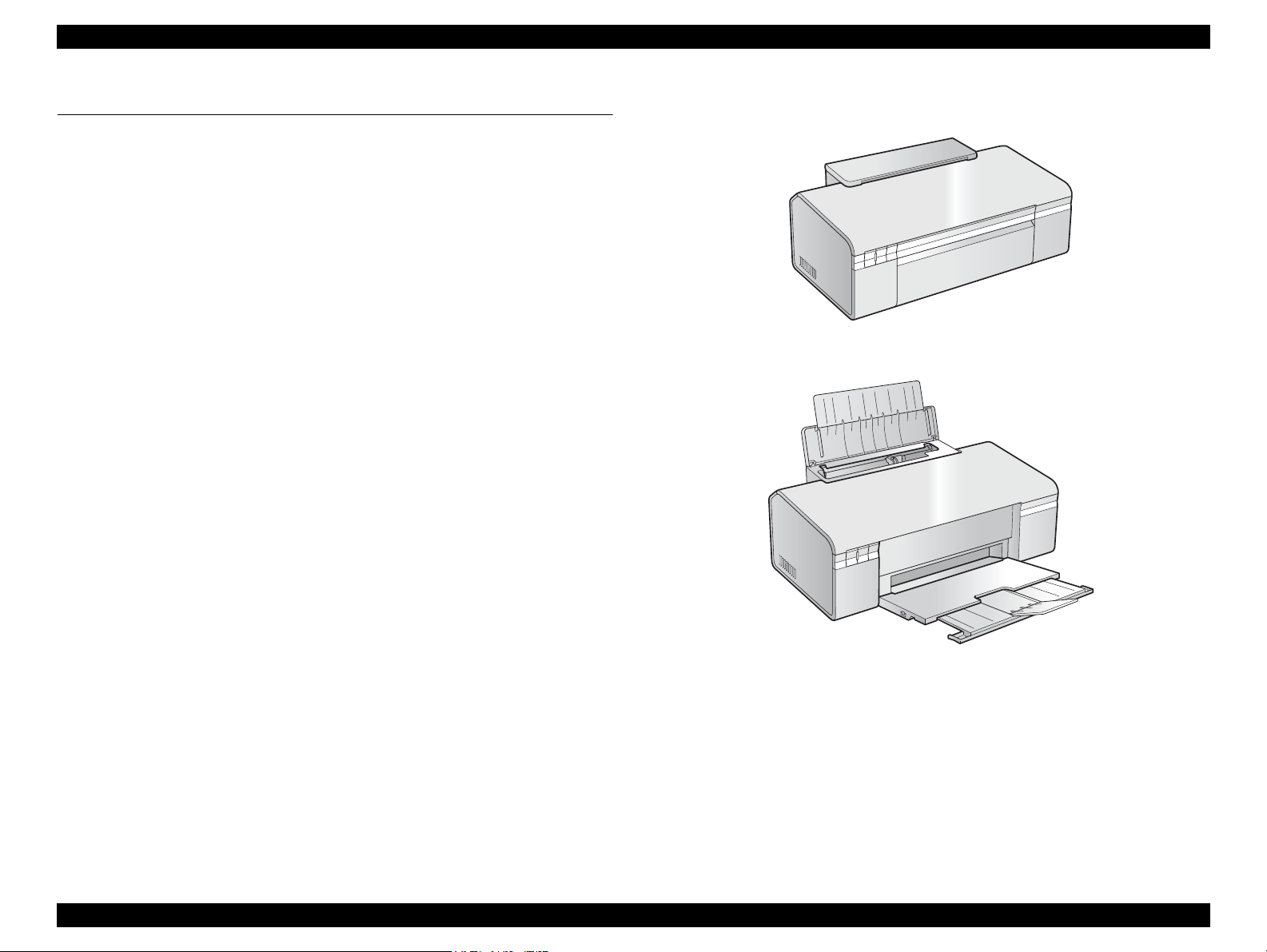
Paper Support & Stacker are Closed
Paper Support & Stacker are Opened
1.1 Features
EPSON Stylus C110/C120/D120 are single-function color ink-jet printers.
The main features are;
High speed & High quality
Maximum print resolution: SMGA 5760 (H) x 1440 (V) dpi
Newly developed F3-3 Mach Turbo II Printhead achieves higher black&white
print speed than ever.
Installs two black ink cartridges as standard.
Newly developed pigment ink is employed.
Borderless printing on specified EPSON brand paper is available.
Control panel
Simple design with three buttons and three indicators (LED).
Dimensions
Dimensions: 435 mm (W) x 240 mm (D) x 161 mm (H)
(Paper support and stacker are closed. Rubber feet are excluded)
Weight: 3.9 kg (without ink cartridges)
Figure 1-1. External View
PRODUCT DESCRIPTION Features 9
EPSON Stylus C110/C120/D120 Revision B
1.2 Printing Specifications
1.2.1 Basic Specifications
Table 1-1. Printer Specifications
Item Specifications
Print method On-demand ink jet
Nozzle configuration Black:180 nozzles x 2
Color: 60 nozzles x 3 (Cyan, Magenta, Yellow)*
Print direction Bi-directional minimum distance printing (logic seeking)
Print resolution Horizontal x Vertical (dpi)
• 360 x 180 • 720 x 720
• 360 x 360 • 1440 x 720
• 360 x 720 • SMGA 5760 x 1440 (1440 x 1440)
Control code • ESC/P Raster command
• EPSON Remote command
Input buffer size T.B.D. Kbytes
Paper feed method Friction feed, using one ASF (Auto Sheet Feeder)
Paper path Top feed, front out
Paper feed rates T.B.D. mm/sec (at 25.4 mm feed)
PF interval Programmable in 0.01764 mm (1/1440 inch) steps
Note * : The No.1 nozzle of each color is used only for executing flushing, and is not used for
printing.Refer to “ 2.2.1 Printhead ” (p.23)
1.2.2 Print Mode
Media
• Plain paper
• Premium Bright
White Paper (EAI)
• Premium Ink Jet
Plain papers (others)
• Ultra Premium
Glossy Photo Paper
(EAI)
• Ultra Glossy Photo
Paper (others)
• Premium Photo Paper
Glossy (EAI)
• Premium Glossy
Photo Paper (others)
• Photo Paper Glossy
(EAI)
• Glossy Photo Paper
(others)
Table 1-2. Print Mode (Color)
Print
Mode
Draft 1 360x180
Draft 2 360x180
Normal 2 360x360
Normal 3 360x360
Fine 360x720
Photo 2 720x720
Best Photo 1440x720
Photo RPM 1440x1440
Fine 360x720
Photo 1 720x720
Best Photo 1440x720
Photo RPM 1440x1440
Fine 360x720
Photo 1 720x720
Best Photo 1440x720
Resolution
(H x V) dpi
Dot Size
(cps)
(400cps)
(400cps)
VSD1
(320cps)
VSD1
(320cps)
VSD2
(245cps)
VSD3
(245cps)
VSD3
(245cps)
VSD3
(245cps)
VSD2
(245cps)
VSD2
(245cps)
VSD3
(245cps)
VSD3
(245cps)
VSD2
(245cps)
VSD2
(245cps)
VSD3
(245cps)
Eco
Eco
Bi-d
Micro
Weave
ON OFF N/A
ON OFF N/A
ON OFF N/A
ON ON N/A
ON ON N/A
ON ON N/A
ON ON OK
ON ON OK
ON ON OK
ON ON OK
ON ON OK
ON ON OK
ON ON OK
ON ON OK
ON ON OK
Border-
less
PRODUCT DESCRIPTION Printing Specifications 10
EPSON Stylus C110/C120/D120 Revision B
Table 1-2. Print Mode (Color)
Media
• Premium Photo Paper
Semi-Gloss (EAI)
• Premium Semigloss
Photo Paper (others)
• Premium
Presentation Paper
Matte (EAI)
• Matte Paper Heavyweight (others)
• Photo Quality Inkjet
Paper* (others)
• Envelope
Note * : Not supported in EAI.
Print
Mode
Photo 1 720x720
Best Photo 1440x720
Photo 1 720x720
Best Photo 1440x720
Photo 1 720x720
Best Photo 1440x720
Normal 2 360x360
Resolution
(H x V) dpi
Fine 360x720
Fine 360x720
Dot Size
(cps)
VSD2
(245cps)
VSD2
(245cps)
VSD3
(245cps)
VSD2
(245cps)
VSD3
(245cps)
VSD2
(245cps)
VSD3
(245cps)
VSD1
(320cps)
VSD2
(245cps)
Bi-d
OFF OFF N/A
OFF ON N/A
Micro
Weave
ON ON OK
ON ON OK
ON ON OK
ON ON OK
ON ON OK
ON ON N/A
ON ON N/A
Border-
less
Media
• Plain paper
• Premium Bright
White Paper (EAI)
• Premium Inkjet
Plain Paper (others)
• Premium
Presentation Paper
Matte (EAI)
• Matte Paper Heavyweight (others)
• Photo Quality Inkjet
Paper* (others)
• Envelope
Table 1-3. Print Mode (Monochrome)
Print
Mode
Draft 3 360x360
Draft 4 360x360
Normal 1 360x360
Normal 3 360x360
Fine 360x720
Photo 2 720x720
Photo 1 720x720
Best Photo 1440x720
Photo 1 720x720
Best Photo 1440x720
Normal 1 360x360
Fine 360x720
Resolution
(H x V) dpi
Dot Size
(cps)
Eco
(400cps)
Eco
(400cps)
VSD1
(320cps)
VSD1
(320cps)
VSD2
(245cps)
VSD3
(245cps)
VSD2
(245cps)
VSD3
(245cps)
VSD2
(245cps)
VSD3
(245cps)
VSD1
(320cps)
VSD2
(245cps)
Bi-d
OFF OFF N/A
OFF ON N/A
Micro
Weave
ON OFF N/A
ON OFF N/A
ON OFF N/A
ON ON N/A
ON ON OK
ON ON N/A
ON ON OK
ON ON OK
ON ON N/A
ON ON N/A
Border-
less
Note * : Not supported in EAI
PRODUCT DESCRIPTION Printing Specifications 11
EPSON Stylus C110/C120/D120 Revision B
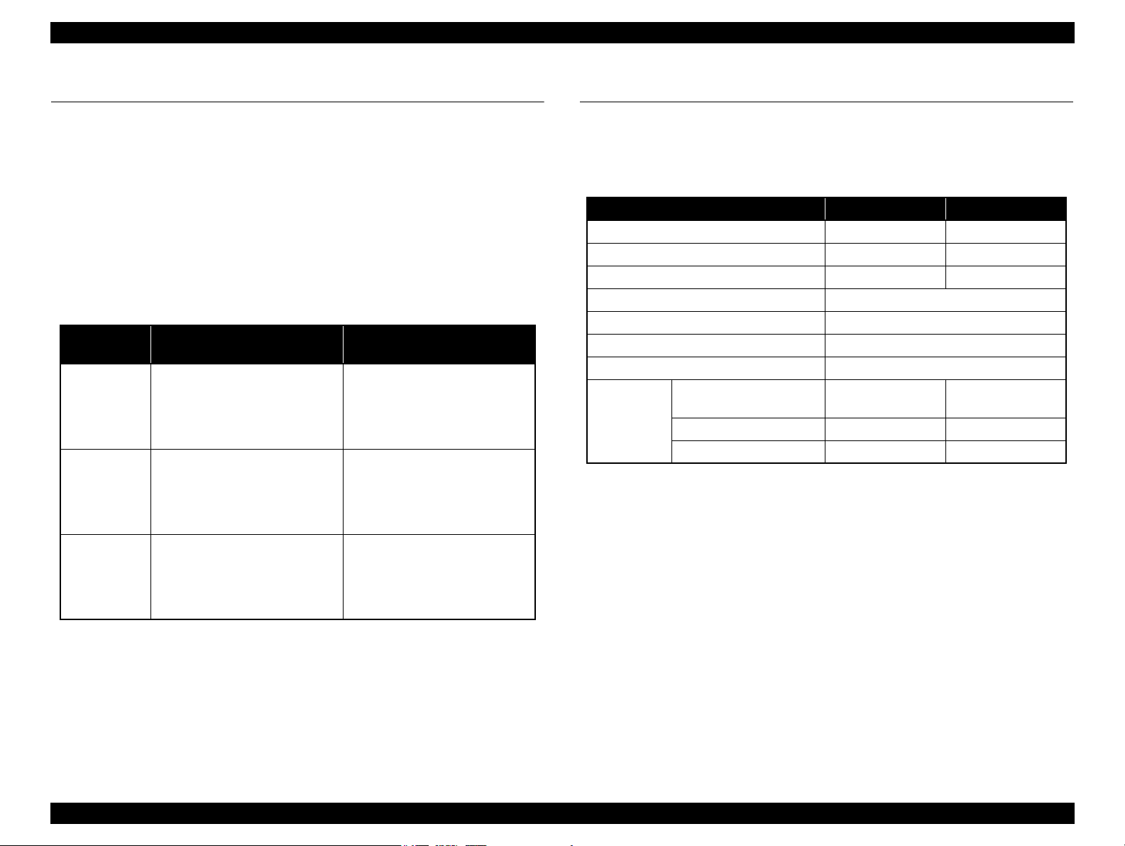
1.2.3 Supported Paper
The table below lists the paper type and sizes supported by the printer. The Supported paper type and sizes vary depending on destinations (between EAI, EUR, and Asia).
Table 1-4. Supported Paper
Paper Name Paper Size
Thickness
(mm)
Legal 215.9 x 355.6 mm (8.5”x14”)
Letter 215.9 x 279.4 mm (8.5”x11”) Y - Y - Y -
A4 210 x 297 mm (8.3”x11.7”) Y - Y - Y -
B5 182 x 257 mm (7.2”x10.1”) - - Y - Y -
Plain paper
A5 148 x 210 mm (5.8”x8.3”) - - Y - Y -
0.08-0.11
Half Letter 139.7 x 215.9 mm (5.5"x8.5”) Y - - - - -
A6 105 x 148 mm (4.2”x5.8”) Y - Y - Y -
User Defined
89 x 127- 329 x 1117.6 mm
(3.56”x 5.08” - 13.16”x44.7”)
Premium Inkjet Plain Paper A4 210 x 297 mm (8.3”x11.7”) 0.11
Letter 215.9 x 279.4 mm (8.5”x11”) 0.11
Premium Bright White Paper (EAI)
Bright White Inkjet Paper (Euro, Asia)
A4 210 x 297 mm (8.3”x11.7”) 0.13
Letter 215.9 x 279.4 mm (8.5”x11”)
Weight
64-90 g/m
(17-24 lb.)
80 g/m
(21 lb.)
90 g/m
(24 lb.)
92.5 g/m
(25 lb.)
EAI EUR Asia
*1
*2
P
B
*1
P
Y - Y - Y -
2
Y - Y - Y -
2
- - Y - Y -
2
Y - - - - -
2
- - Y - Y -
Y Y - - - -
*2
*1
B
P
*2
B
A4 210 x 297 mm (8.3”x11.7”) - Y Y Y Y Y
Ultra Premium Glossy Photo Paper (EAI)*
Ultra Glossy Photo Paper (Euro, Asia)*
8” x 10” 203.2 x 254 mm Y Y - - - -
0.30
290 g/m
(77 lb.)
2
5” x 7” 127 x 178 mm Y Y Y Y - -
4” x 6” 101.6 x 152.4 mm Y Y Y Y Y Y
PRODUCT DESCRIPTION Printing Specifications 12
EPSON Stylus C110/C120/D120 Revision B
C A U T I O N
Table 1-4. Supported Paper
Paper Name Paper Size
Thickness
(mm)
Letter 215.9 x 279.4 mm (8.5”x11”)
A4 210 x 297 mm (8.3”x11.7”) Y Y Y Y Y Y
Premium Photo Paper Glossy (EAI)
Premium Glossy Photo Paper (Euro, Asia)
8” x 10” 203.2 x 254 mm Y Y - - - -
0.27
5” x 7” 127 x 178 mm Y Y Y Y Y Y
4" x 6
"
101.6 x 152.4 mm Y Y Y Y Y Y
16:9 wide 101.6 x 180.6 mm Y Y Y Y Y Y
Letter 215.9 x 279.4 mm (8.5”x11”)
Photo Paper Glossy (EAI)
Glossy Photo Paper (Euro, Asia)
A4 210 x 297 mm (8.3”x11.7”) Y Y Y Y Y Y
0.25
5” x 7” 127 x 178 mm - - Y Y - -
4” x 6” 101.6 x 152.4 mm Y Y Y Y Y Y
Letter 215.9 x 279.4 mm (8.5”x11”)
Premium Photo Paper Semi-Gloss (EAI)
Premium Semigloss Photo Paper (Euro, Asia)
A4 210 x 297 mm (8.3”x11.7”) - - Y Y Y Y
0.27
4” x 6” 101.6 x 152.4 mm Y Y Y Y Y Y
Letter 215.9 x 279.4 mm (8.5”x11”)
Premium Presentation Paper Matte (EAI)
Matte Paper-Heavyweight (Euro, Asia)
A4 210 x 297 mm (8.3”x11.7”) Y Y Y Y Y Y
0.23
8” x 10” 203.2 x 254 mm Y Y - - - -
Photo Quality Inkjet Paper A4 210 x 297 mm (8.3”x11.7”) 0.13
Weight
255 g/m
(68 lb.)
258 g/m
(68 lb.)
250 g/m
(66 lb.)
167 g/m
(44 lb.)
102 g/m
(27 lb.)
EAI EUR Asia
*1
*2
P
B
*1
P
B
Y Y - - - -
2
Y Y - - - -
2
Y Y - - - -
2
Y Y - - - -
2
2
- - Y - Y -
*2
*1
P
*2
B
#10 104.8 x 241.3 mm (4.125”x9.5”)
Envelopes
#DL 110 x 220 mm - - Y - Y -
#C6 114 x 162 mm - - Y - Y -
Note *1 : “Y” in the “P” column stands for “the paper type/size is Supported”.
*2 : “Y” in the “B” column stands for “Borderless printing is available”.
Note * : The nominal weight is 300 g/m
2
PRODUCT DESCRIPTION Printing Specifications 13
Note * :
Y - Y - Y -
-
75-100 g/m
(20-27 lb.)
2
Make sure the paper is not wrinkled, fluffed, torn, or folded.
The curve of paper must be 5 mm or below.
When printing on an envelope, be sure the flap is folded neatly.
Do not use the adhesive envelopes.
Do not use double envelopes and cellophane window envelopes.
EPSON Stylus C110/C120/D120 Revision B
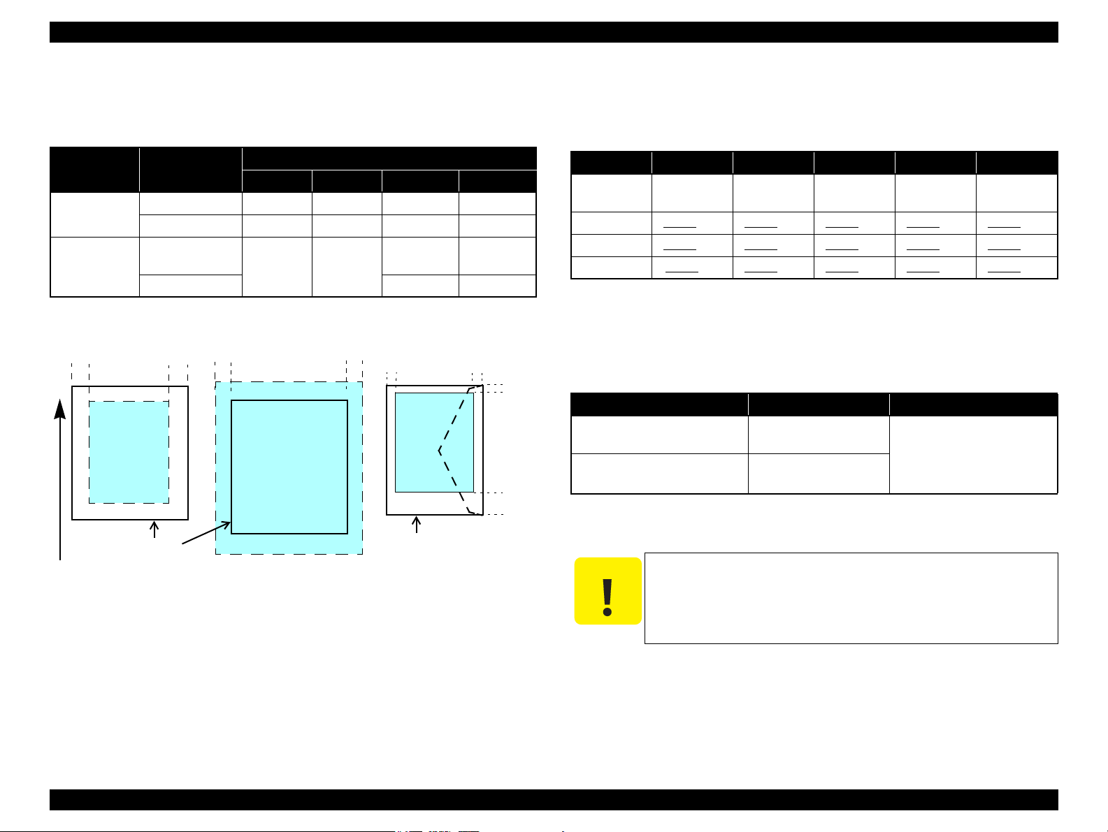
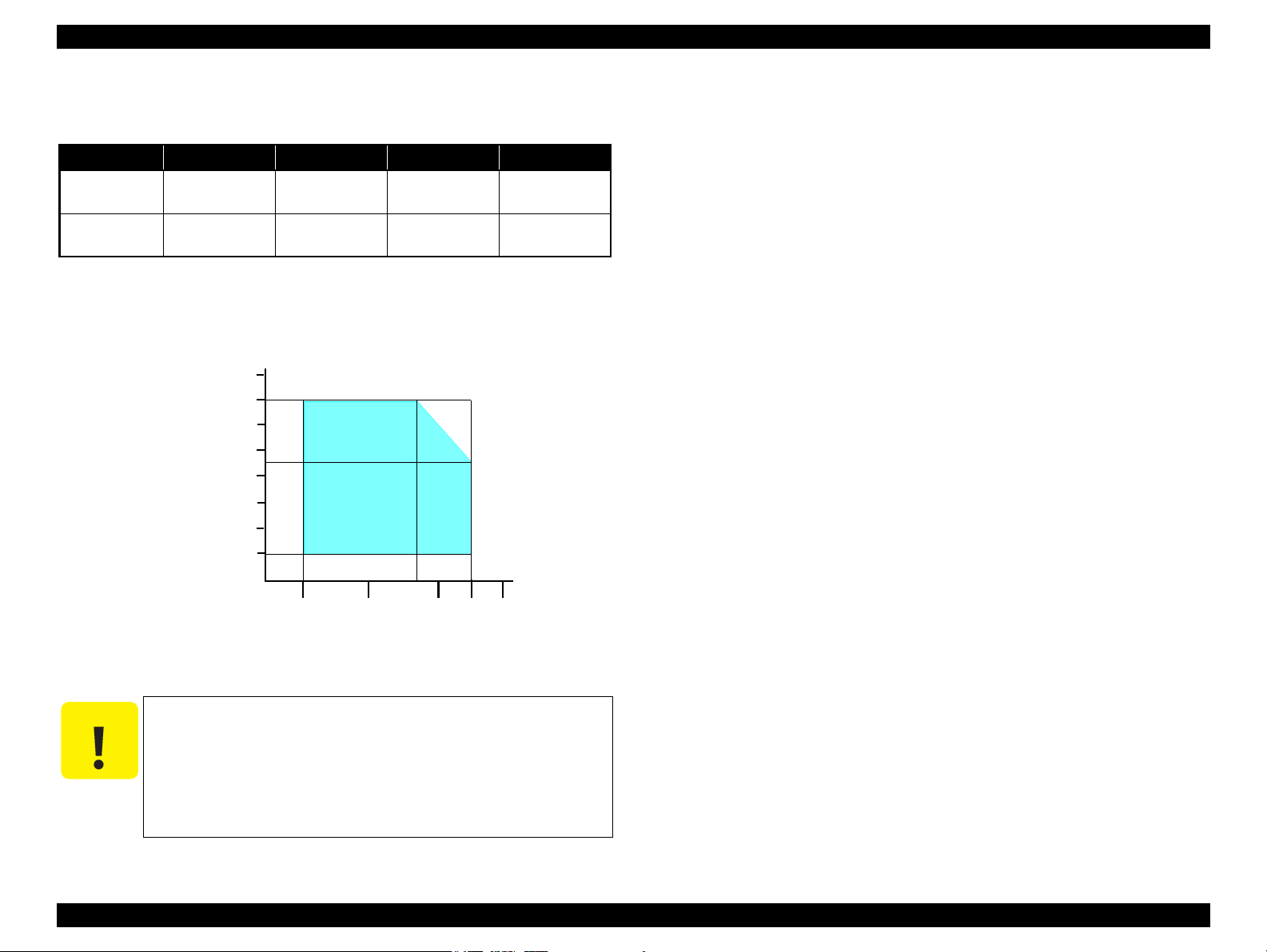
Print Area
LM RM
TM
BM
BM
Cut Sheet (Standard)
Cut Sheet (Borderless)
Paper SIze
LM
RM
TM
BM
Print Area
LM
RM
Print Area
Envelope
Paper Size
TM
Paper Feed Direction
C A U T I O N
1.2.4 Printing Area
The printing area for this printer is shown below.
Table 1-5. Printing Area (Margins)
Print Mode Paper Size
Standard print
Borderless
print
Note * : The margins for Borderless print are margins that bleed off the edges of paper.
Any size 3 mm 3 mm 3 mm 3 mm
Envelope 5 mm 5 mm 3 mm 20 mm
A4/Letter to
5” x 7”
4” x 6” 2.3 mm* 3.39 mm*
Left Right Top Bottom
2.54 mm* 2.54 mm*
Margin
2.3 mm* 3.67 mm*
1.2.5 Ink Cartridge
The product numbers of the EPSON ink cartridges for this printer are shown below.
Table 1-6. Product No. of Ink Cartridges
Color EAI Latin Euro CISMEA Asia
Black T0681 (S) T0731H (S)
Cyan T0692 (3S) T0732 (3S) T0712 (3S) T0732 (3S) T0732 (3S)
Magenta T0693 (3S) T0733 (3S) T0713 (3S) T0733 (3S) T0733 (3S)
Yellow T0694 (3S) T0734 (3S) T0714 (3S) T0734 (3S) T0734 (3S)
Note * : Not supported for EHK.
T0711H (S)
T0711 (2S)
Shelf life
Two years from production date (if unopened), six months after opening package.
Storage Temperature
Table 1-7. Storage Temperature
Situation Storage Temperature Limit
When stored in individual boxes
When installed in main unit
-20 oC to 40 oC
(-4oF to 104oF)
-20 oC to 40 oC
(-4oF to 104oF)
T0731H (S)
T0731 (2S)
1 month max. at 40 oC (104oF)
T0731H (S)*
T0731 (2S)
PRODUCT DESCRIPTION Printing Specifications 14
Figure 1-2. Printing Area
Dimension
12.7 mm (W) x 68 mm (D) x 47 mm (H)
The ink cartridge cannot be refilled.
Do not use expired ink cartridges.
The ink in the ink cartridge freezes at -16 °C (3.2 oF). It takes
about three hours under 25 °C (77
becomes usable.
o
F) until the ink thaws and
EPSON Stylus C110/C120/D120 Revision B
1.3 Interface
The printer has a USB interface of the following specification.
Standards
“Universal Serial Bus Specifications Revision 2.0”
“Universal Serial Bus Device Class Definition for Printing Devices Version 1.1”
Transfer rate: 480 Mbps (High Speed Device)
Data format: NRZI
Compatible connector: USB Series B
Recommended cable length: 2 [m] or less
Table 1-8. Device ID
Product
Name
Stylus C120
Stylus D120
Stylus C110
When IEEE 1284.4 is Enabled When IEEE 1284.4 is Disabled
MFG:EPSON;
CMD:ESCPL2,BDC,D4,D4PX;
MDL:Stylus[SP]C120;
CLS:PRINTER;
DES:EPSON[SP]Stylus[SP]C120;
MFG:EPSON;
CMD:ESCPL2,BDC,D4,D4PX;
MDL:Stylus[SP]D120;
CLS:PRINTER;
DES:EPSON[SP]Stylus[SP]D120;
MFG:EPSON;
CMD:ESCPL2,BDC,D4,D4PX;
MDL:Stylus[SP]C110;
CLS:PRINTER;
DES:EPSON[SP]Stylus[SP]C110;
MFG:EPSON;
CMD:ESCPL2,BDC;
MDL:Stylus[SP]C120;
CLS:PRINTER;
DES:EPSON[SP]Stylus[SP]C120;
MFG:EPSON;
CMD:ESCPL2,BDC;
MDL:Stylus[SP]D120;
CLS:PRINTER;
DES:EPSON[SP]Stylus[SP]D120;
MFG:EPSON;
CMD:ESCPL2,BDC;
MDL:Stylus[SP]C110;
CLS:PRINTER;
DES:EPSON[SP]Stylus[SP]C110;
1.4 General Specifications
1.4.1 Electrical Specifications
Primary power input
Rated power supply voltage 100 to 120 VAC 220 to 240 VAC
Input voltage range 90 to 132 VAC 198 to 264 VAC
Rated current 0.6 A 0.3 A
Rated frequency 50 to 60 Hz
Input frequency range 49.5 to 60.5 Hz
Insulation resistance 3000 V (for one minute)
Energy conservation International Energy Star Program compliant
Power
consumption
Note : If the printer is not operated for more than three minutes, the printer shifts into the
standby mode and reduces the current to the motor to conserve power.
Table 1-9. Primary Power Specifications
Item 100-120 V model 220-240 V model
Printing
(ISO10561 Letter Pattern)
Sleep mode 2.0 W 2.0 W
Standby mode (power-off) 0.2 W 0.4 W
15 W 15 W
PRODUCT DESCRIPTION Interface 15
EPSON Stylus C110/C120/D120 Revision B
C A U T I O N
10/50
27/80
35/9520/68
Temperature (°C/°F)
20
30
40
50
90
80
70
60
Humidity (%)
30/86 40/104
1.4.2 Environmental Conditions
Table 1-10. Environmental Conditions
°F)
*1
3
Humidity
20 to 80%
Condition Temperature
Operating
Storage
(unpacked)
Note *1 : The combined Temperature and Humidity conditions must be within the blue-shaded
range in
*2 : No condensation
*3 : Must be less than 1 month at 40°C.
10 to 35°C
(50 to 95
-20 to 40°C*
(-4°F to 104°F)
Fig.1-3.
Figure 1-3. Temperature/Humidity Range
When returning the repaired printer to the customer, make sure
the Printhead is covered with the cap and the ink cartridge is
installed.
If the Printhead is not covered with the cap when the printer is
off, turn on the printer with the ink cartridge installed, make
sure the Printhead is covered with the cap, and then turn the
printer off.
5 to 85%
*1,2
Shock Vibration
1G
(1 msec or less)
2G
(2 msec or less)
10
10
0.15G,
to 55Hz
0.50G,
to 55Hz
1.4.3 Durability
Total print life: Black 20,000 pages (A4, 3.5% duty),
Color 10,000 pages (A4, ISOFDC24712),
or five years which ever comes first
Printhead: Six billions shots (per nozzle) or five years which ever comes
first
1.4.4 Acoustic Noise
Max. 55dB (when printing from PC, on A4, in default mode)
1.4.5 Safety Approvals (Safety standards/EMI)
USA UL60950-1
FCC Part15 Subpart B Class B
Canada CSA No.60950-1
CAN/CSA-CEI/IEC CISPR 22 Class B
Mexico NOM-019-SCFI-1998
Taiwan CNS13438 Class B
CNS14336
EU EN60950-1
EN55022 Class B
EN61000-3-2, EN61000-3-3
EN55024
Germany EN60950-1
Russia GOST-R (IEC60950-1, CISPR 22)
Singapore IEC60950-1
Korea K60950-1
KN22 Class B
KN61000-4-2/-3/-4/-5/-6/-11
China GB4943
GB9254 Class B, GB17625.1
Argentina IEC60950-1
Australia AS/NZS CISPR22 Class B
PRODUCT DESCRIPTION General Specifications 16
EPSON Stylus C110/C120/D120 Revision B
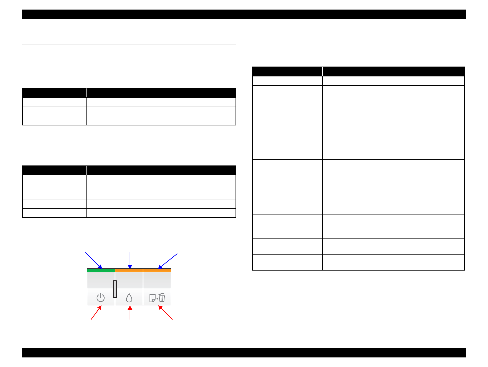
Power Button Paper ButtonInk Button
Power LED Paper LEDInk LED
1.5 Operation Buttons & Indicators (LEDs)
1.5.1 Operation Buttons
The printer has the following three operation buttons.
Table 1-11. Operation Buttons
Button Function
Power Turns the power ON/OFF.
Ink Runs a sequence of ink cartridge replacement or cleaning.
Paper Feeds or ejects paper.
1.5.2 Indicators (LEDs)
Three indicators (LEDs) are provided to indicate settings or printer status.
Table 1-12. Indicators (LEDs)
LED Function
Lights at power-on.
Power LED (green)
Ink LED (orange)*
Paper LED (orange)*
Note *1 : The Ink LED and Paper LED stay OFF when printing from PC.
*2 : See Table 1-14 “Indicators (LEDs) Function” for the LED status at error occurrence.
1
Flashes during some sequence is in progress.
Flashes at high speed during power-OFF sequence.
Lights or flashes when an ink-related error occurs.*
1
Lights or flashes when an paper-related error occurs.*
2
1.5.3 Operation Buttons & LEDs Functions
Detailed information on the buttons and LEDs functions are listed below.
Table 1-13. Operation Button Functions
Button Function
Power • Turns the power ON/OFF
• Runs a sequence of ink cartridge replacement. The carriage
moves to set the ink cartridge to the position for
replacement.
• Moves the carriage to the ink check position when ink level
Ink
Paper
2
Ink
(when held for three seconds
or longer)
Power + Paper *
(combination)
Power + Ink *
(combination)
1
2
low, ink out, or no ink cartridge error has occurred.
• When an ink cartridge is at the ink check position, moves
the carriage to set the cartridge to the position for
replacement, or to the ink check position.
• When an ink cartridge is at the ink replacement position,
moves the carriage to the home position.
• Feeds or ejects paper.
• Recovers from a multi-feed error and resumes the print job.
• Feeds paper that is loaded on the tray when a no-paper error
has occurred.
• Ejects a jammed paper when a paper jam error has
occurred.
• Cancels the print job during printing.
• Runs a head cleaning.
• Runs a sequence of ink cartridge replacement when ink
level low, ink out, or no ink cartridge error has occurred.
•Prints a nozzle check pattern.*
• Forcefully turns the power OFF.
3
Note 1: First press the Paper button and then Power button. The printer will turn On and print
the nozzle check pattern.
2: First press the Power button and then Ink button. Hold them for seven seconds.
3: The nozzle check pattern printed by the printer is shown in Figure 1-5.
Figure 1-4. Buttons & LEDs
PRODUCT DESCRIPTION Operation Buttons & Indicators (LEDs) 17
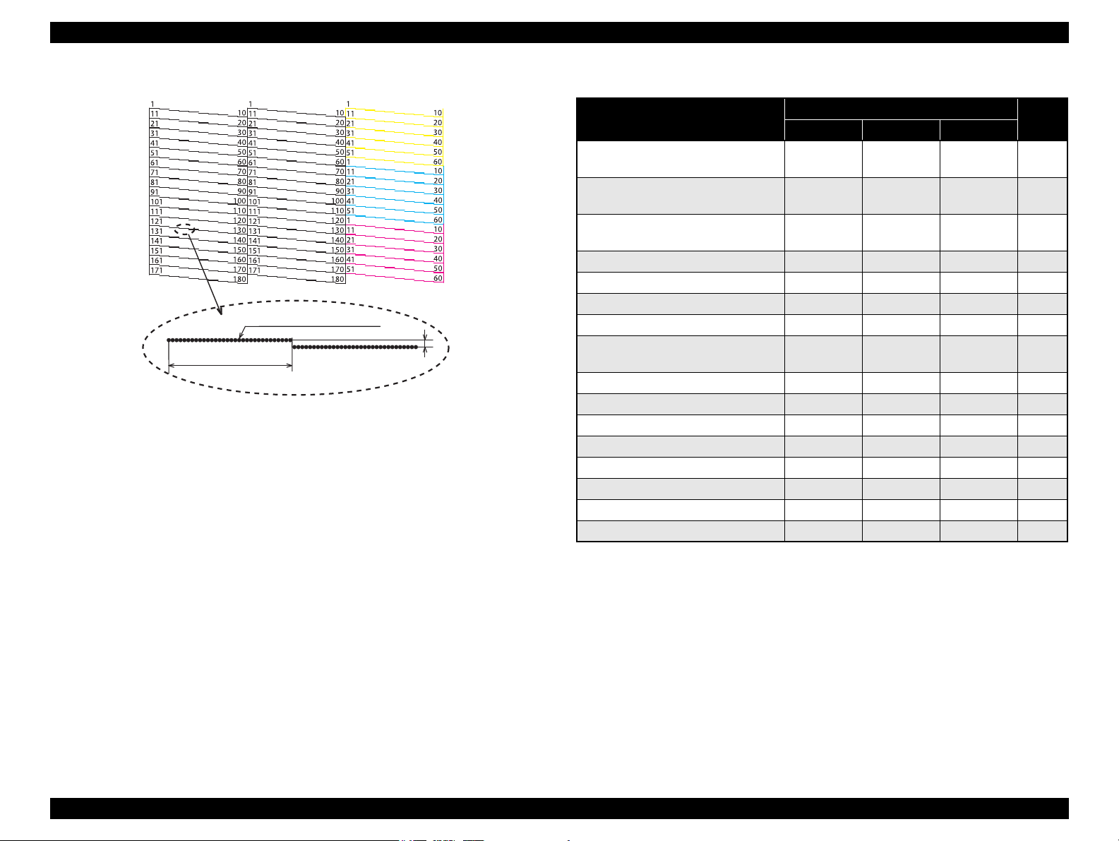
EPSON Stylus C110/C120/D120 Revision B
360 dpi VSD1
0.142 mm (1/180 inch)
32 dots
Note : The numbers shown in the figure are nozzle numbers. They are not printed on
an actual nozzle check pattern.
Table 1-14. Indicators (LEDs) Function
Figure 1-5. Nozzle Check Pattern
Printer Status
Powering off
Power Ink Paper
Flashes at
high speed
Fatal error OFF
Maintenance request OFF
Indicators (LEDs)
OFF OFF 1
Flashes at
high speed
Flashes at
high speed
Flashes
alternately 2
alternately 1
Flashes
Paper jam -- -- Flashes 5
Multi-feed error -- -- ON 6
No paper error -- -- ON 6
Cover open error -- Flashes 2 Flashes 2 6
Ink cartridge replacement is in
progress
Flashes -- -- 7
Ink sequence is in progress Flashes -- -- 8
CSIC error -- ON -- 9
No ink cartridge error or ink-out error -- ON -- 9
During feeding or ejecting paper Flashes -- -- 10
Data processing Flashes -- -- 10
Ink level low error -- Flashes -- 11
Power ON ON -- -- 12
Reset request*
2
ON ON ON -
Pri-
ority*
2
3
1
Note : --: No change
Flash: Repeats turning On and Off every 1.25 seconds.
Flash 2: Repeats On for 0.5 seconds, Off for 0.5 seconds,
On for 0.5 seconds, and Off for 1.0 second.
Flash at high speed: Repeats turning On and Off every 0.5 seconds.
Flashes alternately 1: same as the “Flash”
Flashes alternately 2: Repeats turning Off and On every 1.25 seconds.
Note *1 : When two or more errors occur at the same time, the one with higher priority will be
PRODUCT DESCRIPTION Operation Buttons & Indicators (LEDs) 18
indicated.
*2 : All LEDs light for 0.2 seconds when a reset request is received.

EPSON Stylus C110/C120/D120 Revision B
1.5.4 Errors & Remedies
Error Description Remedies
Fatal error A mechanical error has occurred.
Maintenance request
Paper jam A paper jam has occurred.
No paper Failed to feed paper.
Multi-feed
Ink-out The cartridge has run out of ink. Replace the ink cartridge.
No ink cartridge Ink cartridge(s) was not detected. Replace the ink cartridge.
Wrong ink cartridge
Note : For more information on the remedies, see “ 3.2.2 Error Indications and Fault Occurrence
Causes ” (p.45).
Waste ink pads need to be
replaced.
Multiple sheets of paper were fed
at the same time.
Incorrect ink cartridge(s) was
detected.
Turn the power Off and back it
On.
Replace the waste ink pads and
reset the counter.
Remove the jammed paper and
press the Paper button.
Load paper correctly and press
the Paper button.
Press the Paper button to eject the
multiple sheets.
Replace the ink cartridge.
PRODUCT DESCRIPTION Operation Buttons & Indicators (LEDs) 19

OPERATING PRINCIPLE
CHAPTER
2
EPSON Stylus C110/C120/D120 Revision B
Compression
Spring
LD Roller
Retard Roller
Clutch
Mechanism
PE Sensor
PF Motor
Ink System
Carriage
Unit
CR Encoder
Sensor
PF Roller
Timing Belt
EJ Roller
Star Wheel
Roller
PF ScalePF Encoder Sensor
CR Motor
Cover Open
Sensor
Change Lever
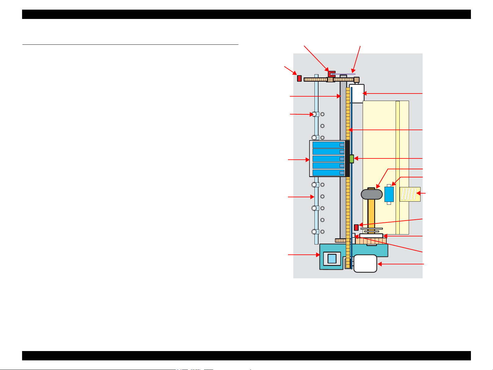
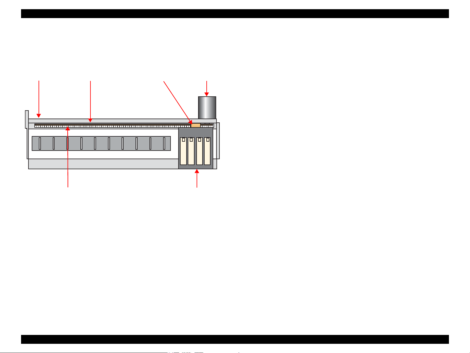
2.1 Overview
This section describes the operating principles of the Printer Mechanism and Electrical
Circuit Boards of Stylus C110/C120/D120.
Stylus C110/C120/D120 employs a newly developed printer mechanism. The
following sections explain about the major components of the new printer mechanism.
2.1.1 Printer Mechanism
Stylus C110/C120/D120 printer mechanism consists of printhead, carriage mechanism,
paper loading mechanism, paper feed mechanism, and ink system.
As the conventional models, Stylus C110/C120/D120 is equipped with two DC
motors; one is used to drive the paper loading, paper feed mechanisms, and the pump
mechanism that includes the carriage lock mechanism, and another one is used to drive
the carriage mechanism. A paper is fed from the rear ASF unit by means of the LD
roller and Retard roller and ejected to the front tray.
OPERATING PRINCIPLE Overview 21
Figure 2-1. Printer Mechanism block diagram
EPSON Stylus C110/C120/D120 Revision B
CR Motor
PF Motor
CR Encoder Sensor
PF Encoder Sensor
CR Contact Module
PE Sensor
Printhead
Cover Open Sensor
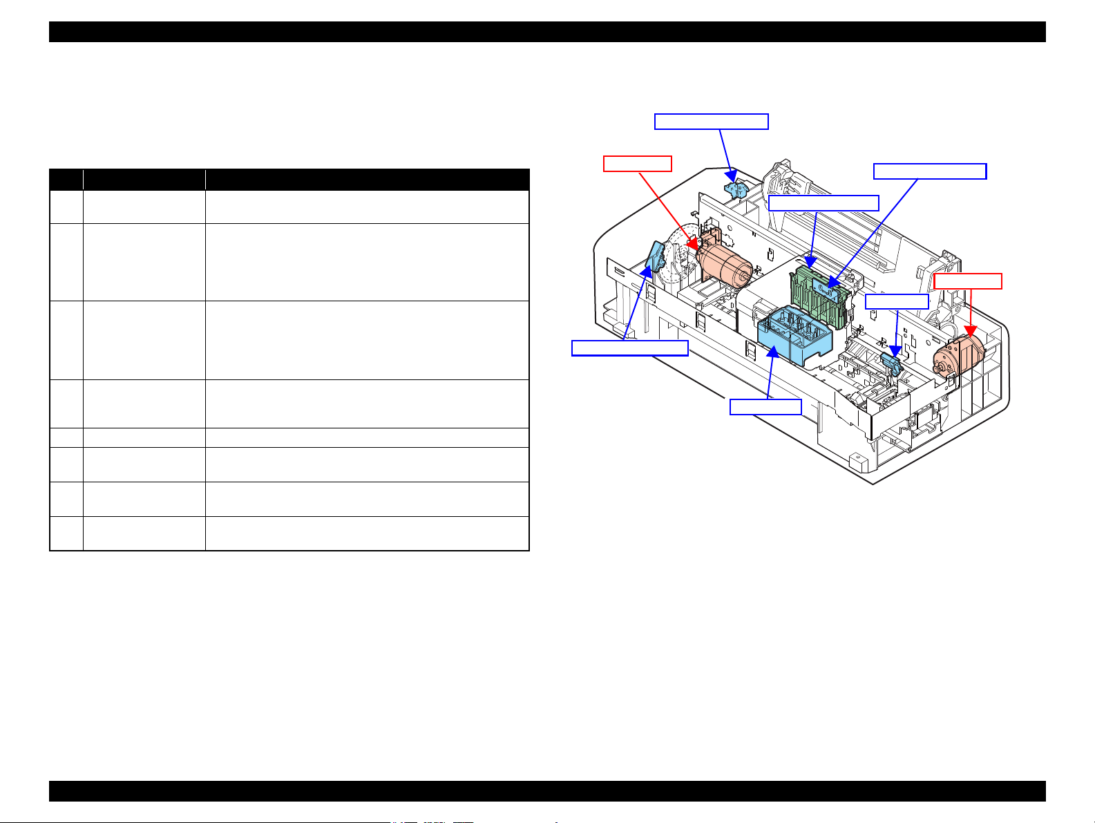
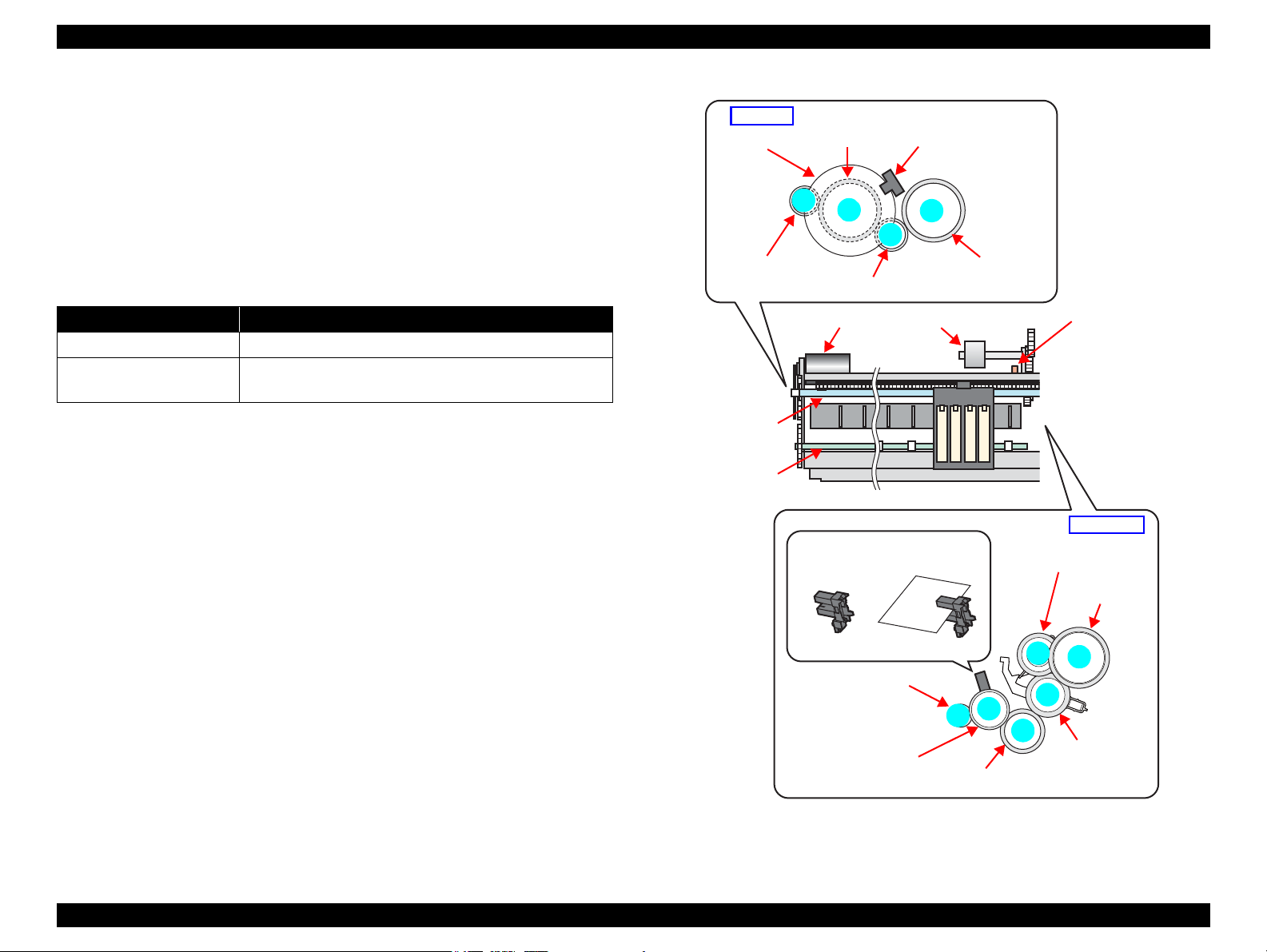
2.1.2 Motors & Sensors
Stylus C110/C120/D120 printer mechanism is equipped with the following printhead,
motors and sensors.
No. Name Specification
1 Printhead
2 CR Motor
3 PF Motor
4 PE Sensor
5 CR contact module CSIC board
6 CR Encoder Sensor
7 PF Encoder Sensor
8 Cover Open Sensor
Figure 2-3 shows their locations.
Table 2-1. List of Motors & Sensors
F3-3 MACH Turbo2 head
(Black: 180 nozzles x 2, Color: 180 nozzles (60 nozzles* x 3 colors) x 1
Type: DC motor
Drive voltage: 42VDC +/- 5% (DRV IC voltage)
Characteristics: Coil resistance: 22.7Ω +/- 10%
Inductance: 15.9mH (1KHz)
Drive method: PWM, constant-current chopping
Type: DC motor
Drive voltage: 42VDC +/- 5% (DRV IC voltage)
Characteristics: Coil resistance: 21.2Ω +/- 10%
Inductance: 17.2 mH (1kHz)
Drive method: PWM, constant-current chopping
Purpose: Detection of paper top and bottom edge, for control to set
paper at the print start position
Type: Photo interrupter
Type: Photo interrupter
Resolution: 180 pulse/inch
Type: Photo interrupter
Resolution: 180 pulse/inch
Purpose: Detection of open/close status of the printer cover
Type: Mechanical contact
Figure 2-2. Motors & Sensors in Printer Mechanism
Note " * " : The No.1 nozzle of each color is used only for executing flushing, and is not used for
printing.
OPERATING PRINCIPLE Overview 22
EPSON Stylus C110/C120/D120 Revision B
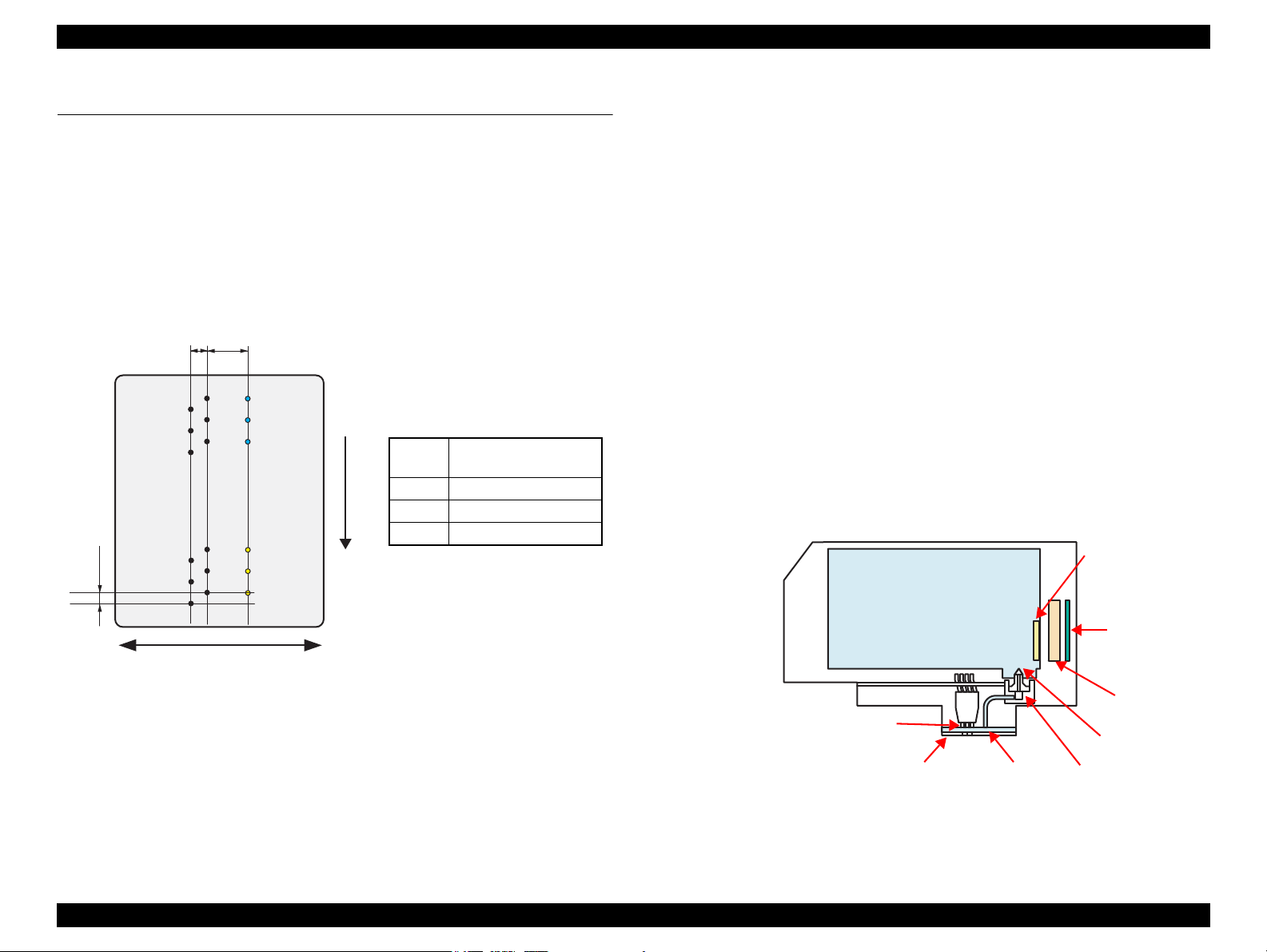
2.258
(64/720inch)
A column B column C column
C#3
C#2
C#1
5.644
(160/720inch)
0.071
(1/360inch)
Carriage movement direction
Paper feed direction
C#180
C#179
C#178
B#3
B#2
B#1
B#180
B#179
B#178
A#3
A#2
A#1
A#180
A#179
A#178
* #1,#61 and #121 nozzles of C column are
used only for flushing, and are not used
for printing.
Black
A column: #1 to #180
B column: #1 to #180
Yellow C column*: #1 to C#60
Magenta C column*: #61 to C#120
Cyan C column*: #121 to C#180
CR Contact
Module
Ink Supply Needle
Ink Cartridge
Ink Cavity
PZT
Nozzle Plate
CSIC Memory Chip
Electric poles
for CSIC
*Head ID is stored in EEPROM
on the main board.
Filter
2.2 Printer Mechanism Operating Principles
2.2.1 Printhead
F3-3 Mach Turbo2 type printhead is employed, which produces variable sized dot and
economy dot. The printhead configuration is as follows.
Nozzle configuration
Black: 180 nozzles x 2
Color: 180 nozzles x 1 (cyan, magenta, yellow)
The nozzle layout as seen from behind the printhead is shown below.
Therefore, whenever the printhead, main board, or the printer mechanism must be
replaced with a new one, the Head ID of the new printhead needs to be written into the
EEPROM using the Adjustment Program. The printer generates appropriate PZT drive
voltage based on the Head ID information.
Following explains the basic components of the printhead.
PZT
PZT is an abbreviation of Piezo Electric Element. Based on the drive waveform
generated on the main board, the PZT selected by the nozzle selector IC on the
printhead pushes the top of the ink cavity, which has ink stored, to eject the ink
from each nozzle on the nozzle plate.
Nozzle Plate
The plate with nozzle holes on the printhead surface is called Nozzle Plate.
Filter
This filter is located beneath the ink supply needle which supply ink to the
printhead from the ink cartridge. The filter is preventing dirt or dust from getting
into the printhead. Any dirt or dust may interrupt normal ink flow or can cause
nozzle clog adversely affecting the print quality.
Ink Cavity
The ink absorbed from the ink cartridge goes through the filter and then is stored
temporarily in this tank called “ink cavity” until PZT is driven.
The basic operating principles of the printhead, which plays a major role in printing,
are the same as the previous printer; on-demand method which uses PZT (Piezo
Electric Element). In order to reduce unit-to-unit variation in ink droplet size, the
printhead has its own Head ID (10-digits code for Stylus C110/C120/D120) which
corrects PZT drive voltage for the printhead.
OPERATING PRINCIPLE Printer Mechanism Operating Principles 23
Figure 2-3. Nozzle Layout
Figure 2-4. Printhead Mechanism
EPSON Stylus C110/C120/D120 Revision B
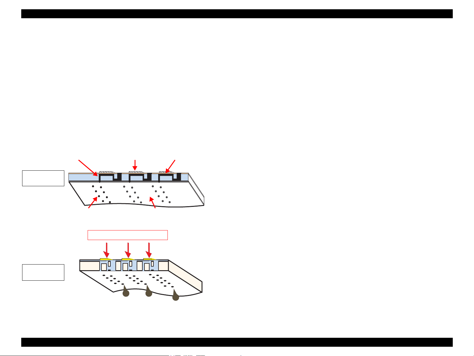
Ink path PZT Ink Cavity
Nozzle Nozzle Plate
PZT drive voltage is applied
When not
firing ink drop
When firing
ink drop
2.2.1.1 Printing Process
This section explains how the printhead of the on-demand inkjet printer fires ink drop
from each of the nozzles.
1. When not firing ink drop
When the printing signal is not output from the C687 main board, or the PZT drive
voltage is not applied, the PZT does not change its shape. Therefore, the PZT does
not push the ink cavity. The ink pressure inside the ink cavity is kept normal. (refer
to
Figure 2-5 (p.24) “When not firing ink drop”)
2. When firing ink drop
When the print signal is output from C687 main board, the nozzle selector IC
provided on the printhead transmits the data in 1-byte unit. Based on the drive
voltage generated on the main board, the PZT selected by the nozzle selector IC
pushes the top of the ink cavity. By this operation, the ink stored in the ink cavity
is ejected from nozzles. (refer to
Figure 2-5 (p.24) “When firing ink drop”)
2.2.1.2 Printing Method
Stylus C110/C120/D120 offers printing with variable sized dot or printing with
economy sized dot.
Variable dot mode
This mode is developed to improve the print quality on Epson designated paper.
Three sizes of dot; micro, middle, and large are automatically selected and used
for printing according to the print data, basically the same as conventional models.
Superior quality can be achieved on the Epson paper.
Economy dot mode
Fixed larger dot is used for printing in economy mode, which enables fast printing
with lower resolutions.
OPERATING PRINCIPLE Printer Mechanism Operating Principles 24
Figure 2-5. How to Fire Ink Drop
EPSON Stylus C110/C120/D120 Revision B
Carriage Unit
Main Frame
Timing Belt
CR Scale CR Encoder Sensor CR Motor
2.2.2 Carriage Mechanism
The carriage mechanism components include the carriage unit (including printhead,
CR encoder sensor), CR motor, timing belt, and CR scale.
The operating principles of the carriage mechanism are described below.
Figure 2-6. Carriage Mechanism
2.2.2.1 CR Motor Control
This printer employs closed-loop control, via the CR motor and an encoder, to control
the carriage speed and position. Since the CR motor is DC motor, the printer controls
the motor in the following methods in order to ensure stable print quality.
Heat control
The heat control over the CR motor is carried out based on the electrical
characteristic of the motor such as torque constants, coil resistance and power
supply voltages.
the CR mechanical load is in the initial state and saved into the EEPROM.
According to the variations measured in the sequence, the voltage is corrected to
make the drive current value constant reducing an individual difference.
CR measurement sequence
To set the appropriate drive voltage for the CR motor in accordance with variation
of the CR motor mechanical load, the printer runs a CR measurement sequence
and stores the measured data into the EEPROM at power-on or in an ink cartridge
replacement sequence. A fatal error occurs if the printer detects that too much load
is applied to the CR motor.
The above control and sequences enable to correct the drive voltage for the CR motor
based on the mechanical load and the electrical characteristic of the motor. According
to the corrected drive voltage, heating value of the motor is calculated. The printer
automatically provides wait time per CR path during printing when the predetermined
heating value is reached.
2.2.2.2 Carriage Home Position Detection
As the previous model, the carriage home position is detected by the CR motor drive
electric current and carriage speed/position signals sent from the CR encoder. The
detection sequence performed at power-on is described below.
1. Drives the CR motor to move the carriage until it contacts with the right
frame, and then stops the CR motor. The carriage position is set as a position
specified number of counts rightward from the home position.
2. Moves the carriage again to the carriage lock position to check the lock for
proper operation.
3. The printer starts to monitor the carriage position through the CR encoder.
The printer causes a fatal error if too much load on the CR motor is detected due to
obstruction on the carriage path or if no carriage position information is obtained due to
CR encoder or CR scale failure.
CR motor drive dispersion measurement sequence
Variations in torque constant, coil resistance and power supply voltage of the
motor are measured in a CR motor drive dispersion measurement sequence when
OPERATING PRINCIPLE Printer Mechanism Operating Principles 25
EPSON Stylus C110/C120/D120 Revision B
1
2
3
4
2
3
4
5
6
7
PF Motor
Pinion Gear
PF Scale
Spur Gear A
(PF Roller)
PF Encoder Sensor
Transmission Gear
Spur Gear B
EJ Roller
Left side
Right side
Spur Gear C
(PF Roller)
Combination Gear A
Combination Gear B
(Pump Unit)
Combination
Gear C
(Change Lever)
Combination
Gear D
Combination Gear E
(LD Roller/Clutch)
PE Sensor
Low signal
<No Paper> <Detects Paper>
High signal
PF Motor
LD Roller PE Sensor
PF Roller
EJ Roller
2.2.3 Paper Loading/Paper Feed Mechanism
The paper loading/feed mechanism are driven and controlled by the PF motor (DC
motor) and the PF encoder.
The PF motor drive force is transmitted to the LD roller and the PF roller via the gears
in the mechanism. In the loading mechanism, paper is fed to the PF roller from the ASF
unit, and the feed mechanism transports the paper during printing and ejects it.
The rotational direction of the PF motor switches between the loading and feed
operations as shown in the table below.
Table 2-2. Rotational Direction of PF Motor & ASF Operations
Rotational Direction* Operations
Clockwise • Releases the change lever from the clutch mechanism.
Counterclockwise
Note " * " : Rotational direction of the PF motor pinion gear as seen from the left side of the
printer.
Figure 2-7 shows how the PF motor drive is transmitted to the LD roller and the PF
roller. (The numbers in the figure indicate the sequence of the drive transmission.)
• Feeds a paper into the printer and transports it.
• Locks the clutch mechanism with the change lever.
The PE sensor detects the paper top and bottom edges during the loading and feeding
operations. When the sensor could not detect the top edge of paper during the loading
operation, the printer causes a paper out error. And when the sensor could not detect
the bottom edge of paper during feeding operation, the printer causes a paper jam error.
For more details on the errors, see
OPERATING PRINCIPLE Printer Mechanism Operating Principles 26
Chapter 3 "TROUBLESHOOTING" (p42).
Figure 2-7. Paper Loading/Feed Mechanism
EPSON Stylus C110/C120/D120 Revision B
Compression
Spring
Paper Back Lever
Hopper
LD Roller
Hopper Release Cam
Paper Back Lever Cam
Extension Spring
Clutch
Clutch Gear
Clutch Lever
Clutch Lock
Tab
Change Lever
Spur Gear C
(PF Roller)
Base Frame
Combination
Gear A
Combination
Gear B
(Pump Unit)
Combination
Gear C
(Change Lever)
Combination Gear D
Combination Gear E
(LD Roller/Clutch)
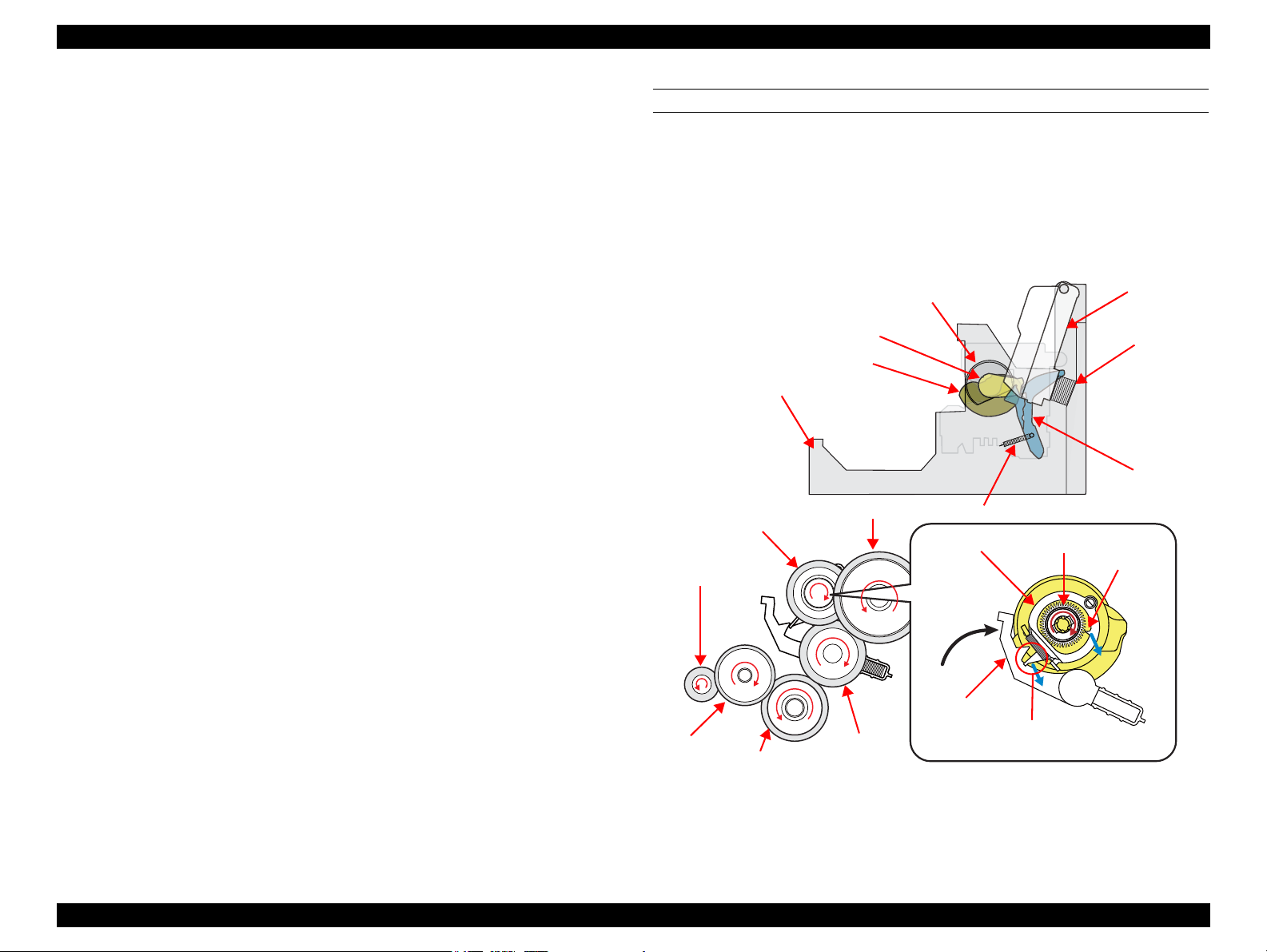
2.2.3.1 Paper Loading Mechanism (ASF Unit)
The paper loading mechanism loads paper from the ASF unit and feeds paper to the PF
roller. The ASF unit includes the hopper, change lever, LD roller shaft, and clutch
mechanism.
The change lever and the clutch mechanism play an important role in the paper loading
operation as described below.
1. ASF home position detection function
The change lever and the clutch mechanism are used to detect the ASF home
position.
The counterclockwise rotation of the PF motor brings the change lever to engage
with the clutch mechanism. The ASF home position is detected by the engagement
of the change lever at the beginning of the paper loading operation. At this time,
paper is not fed to the PF roller because the PF motor drive force is not yet
transmitted to the LD roller shaft.
2. Paper loading function
When the change lever is disengaged from the clutch mechanism by the
counterclockwise rotation of the PF motor pinion gear, the printer changes to the
paper loading state from the ASF home position detection state. The PF motor
drive force is transmitted to the LD roller, and paper is fed from the ASF unit.
The rotation of the two cams on the LD roller feeds paper into the printer.
Larger cam: moves the hopper
Smaller cam: moves the paper back lever
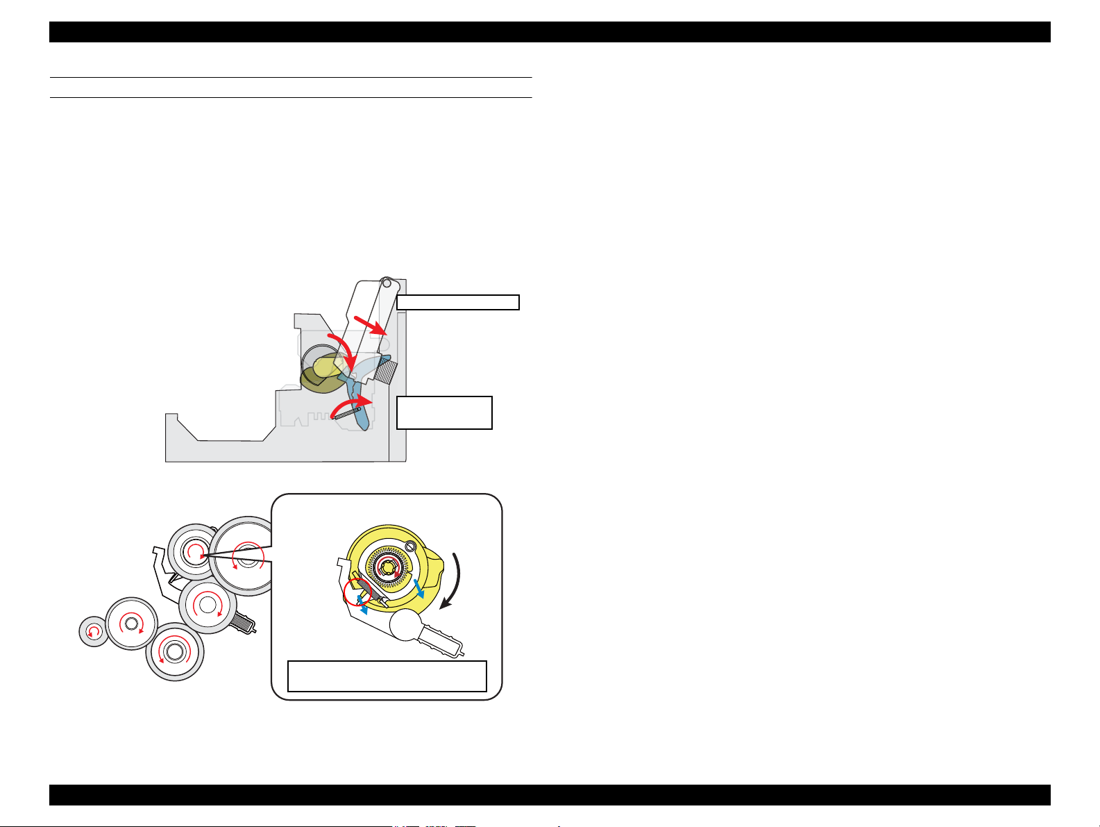
STEP1: ASF HOME POSITION
The counterclockwise rotation of the PF motor pinion gear (as seen from the left of the
printer) causes the change lever to push down on the clutch lever, and the clutch lock
tab is disengaged from the clutch gear as shown in
Figure 2-8. This cuts the PF motor
drive transmission to the LD roller shaft, and the shaft does not move at all. At the
same time, the hopper is pushed down by the two cams on the LD roller shaft, and the
paper back lever is set at the position to prevent paper from being fed. The “ASF home
position” indicates all of the above statuses.
When the first sheet of paper has been fed, the second sheet is returned to the standby
position by the hopper and the paper back lever, which are moved by the cams.
The following sections explain the paper loading sequence and operations of each
components.
OPERATING PRINCIPLE Printer Mechanism Operating Principles 27
Figure 2-8. ASF Home Position
EPSON Stylus C110/C120/D120 Revision B
Extension Spring
Clutch lock
tab engages
PF Motor drive is transmitted to LD
Roller and paper is fed
Paper Back Lever goes to
standby position
Hopper pops up
Paper Back Lever Cam and
Hopper Release Cam rotate
together with LD Roller
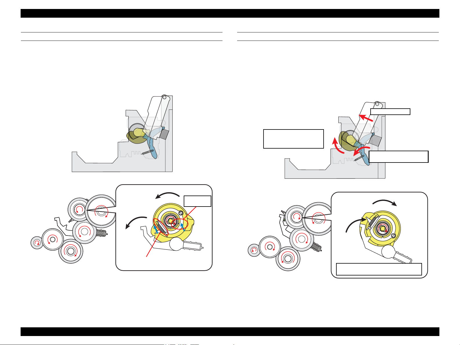
STEP2: RELEASING CLUTCH LEVER TO DRIVE LD ROLLER
When the PF motor pinion gear starts clockwise rotation (as seen from the left side),
the change lever is moved toward the front of the printer to release the clutch lever.
This causes the clutch to engage with the gear by being pulled by the extension spring.
The clutch gear engages with the clutch lock tab and the PF motor drive force is now
can be transmitted to the LD roller shaft.
STEP3: FEEDING PAPER FROM ASF
After the engagement of the clutch, the PF motor pinion gear starts counterclockwise
rotation (as seen from the left side) and the drive force is transmitted to the LD roller
shaft via the clutch lock tab and the clutch gear. When the LD roller starts to rotate, the
paper back lever is returned to its standby position, and the hopper is released from the
cams by being pushed by the spring. This causes a sheet of paper to be caught between
the hopper and the LD roller, and the further rotation of the LD roller feeds the paper
into the printer.
Figure 2-9. Releasing Clutch Lever
Figure 2-10. Feeding Paper from ASF
OPERATING PRINCIPLE Printer Mechanism Operating Principles 28
EPSON Stylus C110/C120/D120 Revision B
Clutch lever is locked again by change
lever to shut off PF motor drive force.
Paper Back Lever
snaps back
Hopper is pushed down
STEP4: ENDING PAPER LOADING OPERATION
Continuous counterclockwise rotation of the LD roller (as seen from the left side) feeds
paper to the PF roller. The LD roller rotation causes the hopper release cam and the
paper back lever cam to push down the hopper and the paper back lever respectively.
The paper back lever returns paper to the standby position to prevent multiple sheets of
paper from being fed at once.
When the LD roller and the clutch reach the ASF home position shown in “Step1” on
the previous page, the clutch lever is locked again by the change lever. This causes the
PF motor drive force not to be transmitted to the paper loading mechanism and to be
transmitted only to the paper feeding mechanism.
Figure 2-11. Ending Paper Loading Operation
OPERATING PRINCIPLE Printer Mechanism Operating Principles 29
EPSON Stylus C110/C120/D120 Revision B
Left side
PF Motor
PF Roller
PF Motor Drive Transmission Path (as seen from the left side of the printer)
• PF motor pinion gear (CCW) → Spur gear A (PF roller) (CW) → Transmission gear (CCW) → Spur gear B (EJ roller) (CW)
PF Motor
Pinion Gear
PF Scale
Spur Gear A
(PF Roller)
Spur Gear B
EJ Roller
PF Encoder Sensor
Transmission Gear
Star Wheel Roller
EJ Roller
Paper Guide Roller
2.2.3.2 Paper Feed Mechanism
The major components of the paper feed mechanism are the PF motor, PF roller, EJ
roller, PE sensor, PF encoder sensor, and PF scale. The sheet of paper fed from the
ASF unit is nipped between two rollers to be transported during printing and to be
ejected.
1. The first two rollers used for feeding the paper are the PF roller and the paper
guide roller mounted on the upper paper guide unit. The PF motor drive force is
transmitted to the paper guide roller via the PF roller.
2. The next two rollers are the EJ roller and the star wheel roller mounted on the Star
Wheel Holder Assy. The PF motor drive force is transmitted to the star wheel
roller via the EJ roller.
The figure below shows how the PF motor pinion gear drive force is transmitted to the
PF roller, EJ roller, paper guide roller and the star wheel roller.
When the PF motor pinion gear starts counterclockwise rotation (as seen from the left
side), the sheet of paper fed from the ASF unit to the PF roller is transported and
ejected from the printer by the PF roller/paper guide roller combination and the EJ
roller/star wheel roller combination.
Figure 2-12. Paper Feed Mechanism
OPERATING PRINCIPLE Printer Mechanism Operating Principles 30
 Loading...