

Page 1
MF1121-03a
CMOS 4-BIT SINGLE CHIP MICROCOMPUTER
S5U1C62000A
(S1C60/62 Family Assembler Package)
Manual
Page 2

NOTICE
No part of this material may be reproduced or duplicated in any form or by any means without the written permission of Seiko
Epson. Seiko Epson reserves the right to make changes to this material without notice. Seiko Epson does not assume any
liability of any kind arising out of any inaccuracies contained in this material or due to its application or use in any product or
circuit and, further, there is no representation that this material is applicable to products requiring high level reliability, such
as medical products. Moreover, no license to any intellectual property rights is granted by implication or otherwise, and there
is no representation or warranty that anything made in accordance with this material will be free from any patent or copyright
infringement of a third party. This material or portions thereof may contain technology or the subject relating to strategic
products under the control of the Foreign Exchange and Foreign Trade Law of Japan and may require an export license from
the Ministry of International Trade and Industry or other approval from another government agency.
Windows 95, Windows 98 and Windows NT are registered trademarks of Microsoft Corporation, U.S.A.
PC/AT and IBM are registered trademarks of International Business Machines Corporation, U.S.A.
All other product names mentioned herein are trademarks and/or registered trademarks of their respective owners.
© SEIKO EPSON CORPORA TION 2002, All rights reserved.
Page 3

Configuration of product number
Devices
S1 C 60N01 F 0A01
00
Packing specifications
00 : Besides tape & reel
0A : TCP BL 2 directions
0B : Tape & reel BACK
0C : TCP BR 2 directions
0D : TCP BT 2 directions
0E : TCP BD 2 directions
0F : Tape & reel FRONT
0G : TCP BT 4 directions
0H : TCP BD 4 directions
0J : TCP SL 2 directions
0K : TCP SR 2 directions
0L : Tape & reel LEFT
0M : TCP ST 2 directions
0N : TCP SD 2 directions
0P : TCP ST 4 directions
0Q : TCP SD 4 directions
0R : Tape & reel RIGHT
99 : Specs not fixed
Specification
Package
D: die form; F: QFP
Model number
Model name
C: microcomputer, digital products
Product classification
S1: semiconductor
Development tools
S5U1 C 60R08 D1 1
00
Packing specifications
00: standard packing
Version
1: Version 1
Tool type
Hx : ICE
Ex : EVA board
Px : Peripheral board
Wx : Flash ROM writer for the microcomputer
Xx : ROM writer peripheral board
Cx : C compiler package
Ax : Assembler package
Dx : Utility tool by the model
Qx : Soft simulator
Corresponding model number
60R08: for S1C60R08
Tool classification
C: microcomputer use
Product classification
S5U1: development tool for semiconductor products
Page 4

Page 5

INTRODUCTION
Introduction
This document describes the development procedure from assembling source files to debugging. It also
explains how to use each development tool of the S1C62 Family Assembler Package common to all the
models of the S1C62 Family.
How To Read the Manual
This manual was edited particularly for those who are engaged in program development. Therefore, it
assumes that the reader already possesses the following fundamental knowledge:
• Basic knowledge about assembler language
• Basic knowledge about the general concept of program development by an assembler
• Basic operating methods for Windows
Before installation
See Chapter 1. Chapter 1 describes the composition of this package, and provides a general outline of
each tool.
Installation
Install the tools following the installation procedure described in Chapter 2.
To understand the flow of program development
See the program development flow in Chapter 3.
For coding
See the necessary parts in Chapter 5. Chapter 5 describes the grammar for the assembler language as
well as the assembler functions. Also refer to the following manuals when coding:
S1C62xxx T echnical Manual
Covers device specifications, and the operation and control method of the peripheral circuits.
S1C6200/6200A Core CPU Manual
Has the instructions and details the functions and operation of the Core CPU.
®
95 or Windows NT®4.0
For debugging
Chapter 9 gives detailed explanation of the debugger. Sections 9.1 to 9.8 give an overview of the
functions of the debugger. See Section 9.9 for details of the debug commands. Also refer to the following manuals to understand operations of the In-Circuit Emulator ICE (S5U1C62000H) and the Evaluation Board (S5U1C62xxxE):
S5U1C62000H Manual
Explains the functions and handling methods of the In-Circuit Emulator ICE.
S5U1C62xxxE Manual
Covers the functions and handling methods of the evaluation board designed to evaluate the
hardware specifications of each model.
For details of each tool
Chapters 4 to 9 explain the details of each tool. Refer to it if necessary.
Once familiar with this package
Refer to the listings of instructions and commands contained in Quick Reference.
S5U1C62000A MANUAL EPSON i
(S1C60/62 FAMILY ASSEMBLER PACKAGE)
Page 6

INTRODUCTION
Manual Notations
This manual was prepared by following the notation rules detailed below:
(1) Sample screens
The sample screens provided in the manual are all examples of displays under Windows®95. These
displays may vary according to the system or fonts used.
(2) Names of each part
The names or designations of the windows, menus and menu commands, buttons, dialog boxes, and
keys are annotated in brackets [ ]. Examples: [Command] window, [File | Exit] menu item ([Exit]
command in [File] menu), [Key Break] button, [q] key, etc.
(3) Names of instructions and commands
The CPU instructions and the debugger commands that can be written in either uppercase or lowercase characters are annotated in lowercase characters in this manual, except for user-specified symbols.
(4) Notation of numeric values
Numeric values are described as follows:
Decimal numbers: Not accompanied by any prefix or suffix (e. g., 123, 1000).
Hexadecimal numbers: Accompanied by the prefix "0x" (e. g., 0x0110, 0xffff).
Binary numbers: Accompanied by the prefix "0b" (e. g., 0b0001, 0b10).
However, please note that some sample displays may indicate hexadecimal or binary numbers not
accompanied by any symbol. Moreover, a hexadecimal number may be expressed as xxxxh, or a
binary number as xxxxb, for reasons of convenience of explanation.
(5) Mouse operations
To c lick: The operation of pressing the left mouse button once, with the cursor (pointer)
placed in the intended location, is expressed as "to click". The clicking operation of
the right mouse button is expressed as "to right-click".
To double-click: Operations of pressing the left mouse button twice in a row, with the cursor (pointer)
placed in the intended location, are all expressed as "to double-click".
To drag: The operation of clicking on a file (icon) with the left mouse button and holding it
down while moving the icon to another location on the screen is expressed as "to
drag".
To select: The operation of selecting a menu command by clicking is expressed as "to select".
(6) Key operations
The operation of pressing a specific key is expressed as "to enter a key" or "to press a key".
A combination of keys using "+", such as [Ctrl]+[C] keys, denotes the operation of pressing the [C] key
while the [Ctrl] key is held down. Sample entries through the keyboard are not indicated in [ ].
Moreover, the operation of pressing the [Enter] key in sample entries is represented by "↵".
In this manual, all the operations that can be executed with the mouse are described only as mouse
operations. For operating procedures executed through the keyboard, refer to the Windows manual or
help screens.
(7) General forms of commands, startup options, and messages
Items given in [ ] are those to be selected by the user, and they will work without any key entry
involved.
An annotation enclosed in < > indicates that a specific name should be placed here. For example, <file
name> needs to be replaced with an actual file name.
Items enclosed in { } and separated with | indicate that you should choose an item. For example, {A |
B} needs to have either A or B selected.
ii EPSON S5U1C62000A MANUAL
(S1C60/62 FAMILY ASSEMBLER PACKAGE)
Page 7

CONTENTS
Contents
CHAPTER 1GENERAL ................................................................................................ 1
1.1 Features.........................................................................................................1
1.2 Tool Composition ..........................................................................................2
1.2.1 Composition of Package.............................................................................. 2
1.2.2 Outline of Software Tools ............................................................................ 2
CHAPTER 2INSTALLATION .......................................................................................... 3
2.1 Working Environment ....................................................................................3
2.2 Installation Method ....................................................................................... 4
2.3 Directories and Files after Installation.........................................................6
CHAPTER 3SOFTWARE DEVELOPMENT PROCEDURE ..................................................... 7
3.1 Software Development Flow .........................................................................7
3.2 Development Using Work Bench ................................................................... 8
3.2.1 Starting Up the Work Bench ........................................................................ 8
3.2.2 Creating a New Project............................................................................... 9
3.2.3 Editing Source Files .................................................................................... 9
3.2.4 Configuration of Tool Options ................................................................... 11
3.2.5 Building an Executable Object .................................................................. 12
3.2.6 Debugging.................................................................................................. 13
CHAPTER 4WORK BENCH......................................................................................... 14
4.1 Features........................................................................................................14
4.2 Starting Up and Terminating the Work Bench.............................................. 14
4.3 Work Bench Windows ................................................................................... 15
4.3.1 Window Configuration ............................................................................... 15
4.3.2 Window Manipulation ................................................................................ 16
4.4 Toolbar and Buttons ..................................................................................... 20
4.4.1 Standard Toolbar........................................................................................ 20
4.4.2 Build Toolbar ............................................................................................. 21
4.4.3 Window Toolbar ......................................................................................... 21
4.4.4 Toolbar Manipulation ................................................................................ 22
4.4.5 [Insert into project] Button on a [Edit] Window........................................ 22
4.5 Menus ........................................................................................................... 23
4.5.1 [File] Menu ................................................................................................ 23
4.5.2 [Edit] Menu................................................................................................ 24
4.5.3 [View] Menu............................................................................................... 24
4.5.4 [Insert] Menu ............................................................................................. 25
4.5.5 [Build] Menu.............................................................................................. 25
4.5.6 [Tools] Menu.............................................................................................. 25
4.5.7 [Window] Menu ......................................................................................... 26
4.5.8 [Help] Menu .............................................................................................. 26
4.6 Project and Work Space ...............................................................................27
4.6.1 Creating a New Project.............................................................................. 27
4.6.2 Inserting Sources into a Project................................................................. 28
4.6.3 [Project] Window ....................................................................................... 29
4.6.4 Opening and Closing a Project.................................................................. 29
4.6.5 Files in the Work Space Folder ................................................................... 30
S5U1C62000A MANUAL EPSON iii
(S1C60/62 FAMILY ASSEMBLER PACKAGE)
Page 8

CONTENTS
4.7 Source Editor ............................................................................................... 31
4.7.1 Creating a New Source or Header File...................................................... 31
4.7.2 Loading and Saving Files .......................................................................... 32
4.7.3 Edit Function ............................................................................................. 33
4.7.4 Tag Jump Function ..................................................................................... 36
4.7.5 Printing ...................................................................................................... 37
4.8 Build Task ..................................................................................................... 37
4.8.1 Preparing a Build Task .............................................................................. 37
4.8.2 Building an Executable Object .................................................................. 37
4.8.3 Debugging.................................................................................................. 38
4.8.4 Executing Other Tools ................................................................................ 39
4.9 Tool Option Settings ..................................................................................... 41
4.9.1 Assembler Options ..................................................................................... 41
4.9.2 Linker Options ........................................................................................... 42
4.9.3 Debugger Options ...................................................................................... 44
4.9.4 HEX Converter Options ............................................................................. 44
4.10 Short-Cut Key List........................................................................................ 45
4.11 Error Messages ............................................................................................45
4.12 Precautions ..................................................................................................46
CHAPTER 5ASSEMBLER ............................................................................................ 47
5.1 Functions...................................................................................................... 47
5.2 Input/Output Files ........................................................................................ 47
5.2.1 Input File.................................................................................................... 47
5.2.2 Output Files................................................................................................ 48
5.3 Starting Method............................................................................................ 49
5.4 Messages ......................................................................................................50
5.5 Grammar of Assembly Source ...................................................................... 51
5.5.1 Statements .................................................................................................. 51
5.5.2 Instructions (Mnemonics and Pseudo-instructions) .................................. 53
5.5.3 Labels ......................................................................................................... 54
5.5.4 Comments................................................................................................... 56
5.5.5 Blank Lines ................................................................................................ 56
5.5.6 Register Names .......................................................................................... 56
5.5.7 Numerical Notations .................................................................................. 57
5.5.8 Symbols ...................................................................................................... 58
5.5.9 Operators ................................................................................................... 58
5.5.10 Location Counter Symbol "$" .................................................................. 60
5.6 Section Management .................................................................................... 61
5.6.1 Definition of Sections ................................................................................. 61
5.6.2 Absolute and Relocatable Sections ............................................................ 61
5.6.3 Sample Definition of Sections .................................................................... 62
5.7 Assembler Pseudo-Instructions.................................................................... 63
5.7.1 Include Instruction (#include).................................................................... 64
5.7.2 Define Instruction (#define) ....................................................................... 65
5.7.3 Macro Instructions (#macro ... #endm)...................................................... 67
5.7.4 Conditional Assembly Instructions
(#ifdef ... #else ... #endif, #ifndef... #else ... #endif) ................................... 69
5.7.5 Section Defining Pseudo-Instructions (.code, .bss) ................................... 71
5.7.6 Location Defining Pseudo-Instructions (.org, .bank, .page, .align) .......... 72
5.7.7 Symbol Defining Pseudo-Instruction (.set) ................................................ 77
5.7.8 Data Defining Pseudo-Instruction (.codeword)......................................... 78
5.7.9 Area Securing Pseudo-Instructions (.comm, .lcomm)................................ 79
iv EPSON S5U1C62000A MANUAL
(S1C60/62 FAMILY ASSEMBLER PACKAGE)
Page 9

CONTENTS
5.7.10 Global Declaration Pseudo-Instruction (.global).................................... 80
5.7.11 List Control Pseudo-Instructions (.list, .nolist)........................................ 81
5.7.12 Source Debugging Information Pseudo-Instructions (.stabs, .stabn)...... 81
5.7.13 Comment Adding Function ...................................................................... 82
5.7.14 Priority of Pseudo-Instructions................................................................ 82
5.8 Summary of Compatibility with the Older Tool ...........................................83
5.9 Relocatable List File ....................................................................................84
5.10 Sample Executions ....................................................................................... 85
5.11 Error/Warning Messages.............................................................................. 87
5.11.1 Errors ....................................................................................................... 87
5.11.2 W arning .................................................................................................... 88
5.12 Precautions ..................................................................................................88
CHAPTER 6LINKER .................................................................................................. 89
6.1 Functions...................................................................................................... 89
6.2 Input/Output Files ........................................................................................ 89
6.2.1 Input Files .................................................................................................. 89
6.2.2 Output Files................................................................................................ 90
6.3 Starting Method............................................................................................ 91
6.4 Messages ......................................................................................................94
6.5 Linker Command File................................................................................... 95
6.6 Link Map File............................................................................................... 96
6.7 Symbol File...................................................................................................97
6.8 Absolute List File ......................................................................................... 98
6.9 Cross Reference File .................................................................................... 99
6.10 Linking ........................................................................................................100
6.11 Automatic Insertion/Removal/Correction of "pset" Instruction.................. 102
6.12 Error/Warning Messages............................................................................. 103
6.12.1 Errors ...................................................................................................... 103
6.12.2 W arning ................................................................................................... 103
6.13 Precautions .................................................................................................104
CHAPTER 7HEX CONVERTER ................................................................................... 105
7.1 Functions..................................................................................................... 105
7.2 Input/Output Files ....................................................................................... 105
7.2.1 Input Files ................................................................................................. 105
7.2.2 Output Files............................................................................................... 105
7.3 Starting Method........................................................................................... 106
7.4 Messages .....................................................................................................107
7.5 Output Hex Files ......................................................................................... 108
7.5.1 Hex File Configuration ............................................................................. 108
7.5.2 Intel-HEX Format ..................................................................................... 108
7.5.3 Motorola-S Format.................................................................................... 109
7.5.4 Conversion Range ..................................................................................... 109
7.6 Error/Warning Messages............................................................................. 110
7.6.1 Errors ........................................................................................................ 110
7.6.2 W arning ..................................................................................................... 110
7.7 Precautions ................................................................................................. 111
S5U1C62000A MANUAL EPSON v
(S1C60/62 FAMILY ASSEMBLER PACKAGE)
Page 10

CONTENTS
CHAPTER 8DISASSEMBLER ...................................................................................... 112
8.1 Functions..................................................................................................... 112
8.2 Input/Output Files ....................................................................................... 112
8.2.1 Input Files ................................................................................................. 112
8.2.2 Output Files............................................................................................... 112
8.3 Starting Method........................................................................................... 113
8.4 Messages .....................................................................................................114
8.5 Disassembling Output ................................................................................. 115
8.6 Error/Warning Messages............................................................................. 118
8.6.1 Errors ........................................................................................................ 118
8.6.2 W arning ..................................................................................................... 118
CHAPTER 9DEBUGGER ............................................................................................ 119
9.1 Features.......................................................................................................119
9.2 Input/Output Files ....................................................................................... 119
9.2.1 Input Files ................................................................................................. 119
9.2.2 Output Files............................................................................................... 120
9.3 Starting Method........................................................................................... 121
9.3.1 Start-up Format......................................................................................... 121
9.3.2 Start-up Options........................................................................................ 121
9.3.3 Start-up Messages ..................................................................................... 122
9.3.4 Hardware Check at Start-up ..................................................................... 122
9.3.5 Method of Termination .............................................................................. 123
9.4 Windows ...................................................................................................... 124
9.4.1 Basic Structure of Window ........................................................................ 124
9.4.2 [Command] Window ................................................................................. 126
9.4.3 [Source] Window....................................................................................... 127
9.4.4 [Data] Window.......................................................................................... 129
9.4.5 [Register] Window .................................................................................... 129
9.4.6 [Trace] Window......................................................................................... 130
9.5 Tool Bar....................................................................................................... 131
9.5.1 Tool Bar Structure ..................................................................................... 131
9.5.2 [Key Break] Button ................................................................................... 131
9.5.3 [Load File] and [Load Option] Buttons ................................................... 131
9.5.4 [Source], [Mix], and [Unassemble] Buttons ............................................ 131
9.5.5 [Go], [Go to Cursor], [Go from Reset], [Step], [Next],
and [Reset] Buttons................................................................................... 131
9.5.6 [Break] Button .......................................................................................... 132
9.5.7 [Help] Button ............................................................................................ 132
9.6 Menu............................................................................................................ 133
9.6.1 Menu Structure.......................................................................................... 133
9.6.2 [File] Menu ............................................................................................... 133
9.6.3 [Run] Menu ............................................................................................... 133
9.6.4 [Break] Menu............................................................................................ 134
9.6.5 [Trace] Menu ............................................................................................ 134
9.6.6 [View] Menu.............................................................................................. 134
9.6.7 [Option] Menu .......................................................................................... 135
9.6.8 [Windows] Menu....................................................................................... 135
9.6.9 [Help] Menu ............................................................................................. 135
9.7 Method for Executing Commands...............................................................136
9.7.1 Entering Commands from Keyboard......................................................... 136
9.7.2 Executing from Menu or Tool Bar............................................................. 138
9.7.3 Executing from a Command File .............................................................. 139
9.7.4 Log File ..................................................................................................... 140
vi EPSON S5U1C62000A MANUAL
(S1C60/62 FAMILY ASSEMBLER PACKAGE)
Page 11

CONTENTS
9.8 Debug Functions .........................................................................................141
9.8.1 Loading Program and Option Data.......................................................... 141
9.8.2 Source Display and Symbolic Debugging Function ................................. 142
9.8.3 Displaying and Modifying Program, Data, and Register ......................... 144
9.8.4 Executing Program ................................................................................... 146
9.8.5 Break Functions ........................................................................................ 148
9.8.6 Trace Functions......................................................................................... 150
9.8.7 Coverage ................................................................................................... 153
9.9 Command Reference ................................................................................... 154
9.9.1 Command List ........................................................................................... 154
9.9.2 Reference for Each Command .................................................................. 155
9.9.3 Program Memory Operation..................................................................... 156
as (assemble mnemonic).............................................................. 156
pe (program memory enter)......................................................... 158
pf (program memory fill) ............................................................. 159
pm (program memory move)........................................................ 160
9.9.4 Data Memory Operation........................................................................... 161
dd (data memory dump)............................................................... 161
de (data memory enter) ............................................................... 163
df (data memory fill) .................................................................... 165
dm (data memory move) .............................................................. 166
9.9.5 Register Operation .................................................................................... 167
rd (register display) ..................................................................... 167
rs (register set)............................................................................. 168
9.9.6 Program Execution ................................................................................... 169
g (go) ........................................................................................... 169
gr (go after reset CPU)................................................................ 171
s (step) ......................................................................................... 172
n (next) ......................................................................................... 173
9.9.7 CPU Reset ................................................................................................. 174
rst (reset CPU)............................................................................. 174
9.9.8 Break ......................................................................................................... 175
bp (break point set)...................................................................... 175
bpc (break point clear) ................................................................ 177
bd (data break) ............................................................................ 178
bdc (data break clear) ................................................................. 180
br (register break) ........................................................................ 181
brc (r egister break clear) ............................................................. 183
bm (multiple break) ..................................................................... 184
bmc (multiple break clear) .......................................................... 186
bl (break point list) ...................................................................... 187
bac (break all clear) .................................................................... 188
be (break enable) ......................................................................... 189
bsyn (break disable)..................................................................... 190
9.9.9 Program Display....................................................................................... 191
u (unassemble)............................................................................. 191
sc (source code) ........................................................................... 192
m (mix)......................................................................................... 193
9.9.10 Symbol Information................................................................................. 194
sy (symbol list) ............................................................................. 194
9.9.11 Load File................................................................................................. 195
lf (load file) .................................................................................. 195
lo (load option) ............................................................................ 196
9.9.12 ROM Access ............................................................................................ 197
rp (ROM program load)............................................................... 197
vp (ROM program verify) ............................................................ 198
rom (ROM type) ........................................................................... 199
S5U1C62000A MANUAL EPSON vii
(S1C60/62 FAMILY ASSEMBLER PACKAGE)
Page 12

CONTENTS
9.9.13 Trace........................................................................................................ 200
tc (trace condition) ...................................................................... 200
ta (trace area).............................................................................. 201
tac (trace area clear)................................................................... 203
tp (trace pointer).......................................................................... 204
td (trace data display) ................................................................. 205
ts (trace search) ........................................................................... 207
tf (trace file) ................................................................................. 209
9.9.14 Coverage ................................................................................................. 210
cv (coverage) ............................................................................... 210
cvc (coverage clear) .................................................................... 211
9.9.15 Command File......................................................................................... 212
com (execute command file) ........................................................ 212
rec (record commands to a file)................................................... 213
9.9.16 log ........................................................................................................... 214
log (log) ....................................................................................... 214
9.9.17 Map Information ..................................................................................... 215
ma (map information).................................................................. 215
9.9.18 Mode Setting ........................................................................................... 216
otf (on-the-fly display) ................................................................. 216
tim (time or step mode)................................................................ 217
9.9.19 Self Diagnosis ......................................................................................... 218
chk (self diagnostic test) .............................................................. 218
9.9.20 Quit ......................................................................................................... 219
q (quit) ......................................................................................... 219
9.10 Error/Warning Messages.............................................................................. 220
QUICK REFERENCE ................................................................................................... 221
viii EPSON S5U1C62000A MANUAL
(S1C60/62 FAMILY ASSEMBLER PACKAGE)
Page 13

CHAPTER 1: GENERAL
CHAPTER 1GENERAL
1.1 Features
The S1C62 Family Assembler Package contains software development tools that are common to all the
models of the S1C62 Family. The package comes as an efficient working environment for development
tasks, ranging from source program assembly to debugging.
Its principal features are as follows:
Simple composition
A task from assembly to debugging can be made with minimal tools.
Integrated working environment
A Windows-based integrated environment allows the tool chain to be used on its Windows GUI
interface.
Modular programming
The relocatable assembler lets you develop a program which is made up of multiple sources. This
makes it possible to keep a common part independently and to use it as a part or a basis for the next
program.
Source debugging
A debugger can display an assembler source to show its execution status and allow debugging
operations on it. This makes debugging much easier to perform.
Common to all S1C62 chips
The tools (workbench, assembler, linker, hex converter, disassembler, and debugger) are common to
all S1C62 Family models except for several chip dependent masking tools ("Dev" tools). The chip
dependent information is read from the ICE parameter file for each chip.
Complete compatibility with old syntax sources
By supporting old syntax together with the new syntax, an existing ".dat" sources written for old 62
tools are available with these new tools.
S5U1C62000A MANUAL EPSON 1
(S1C60/62 FAMILY ASSEMBLER PACKAGE)
Page 14

CHAPTER 1: GENERAL
1.2 Tool Composition
1.2.1 Composition of Package
The S1C62 Family Assembler Package contains the items listed below. When it is unpacked, make sure
that all items are supplied.
1) CD-ROM................................................................................. One
2) Warranty card ......................................................................... One each in English and Japanese
1.2.2 Outline of Software Tools
The following shows the outlines of the software tools included in the package:
Assembler (as62.exe)
Converts the mnemonic of the source files into object codes (machine language) of the S1C62. The
results are output in a relocatable object file. This assembler includes preprocessing functions such as
macro definition/call, conditional assembly, and file-include functions.
Linker (lk62.exe)
Links the relocatable objects created by the assembler by fixing the memory locations, and creates
executable absolute object codes. The linker also provides an auto PSET insertion/correction function
allowing the programmer to create sources without having to know branch destination page numbers.
Hex converter (hx62.exe)
Converts an absolute object in IEEE-695 format output from the linker into ROM-image data in IntelHEX format or Motorola-S format. This conversion is needed when making the ROM or when creating mask data using the development tools provided with each model.
Disassembler (ds62.exe)
Disassembles an absolute object file in IEEE-695 format or a hex file in Intel-HEX format, and restores
it to a source format file. The restored source file can be processed in the assembler/linker/hex
converter to obtain the same object or hex file.
Debugger (db62.exe)
This software performs debugging by controlling the ICE hardware tool. Commands that are used
frequently, such as break and step, are registered on the tool bar, minimizing the necessary keyboard
operations. Moreover, sources, registers, and command execution results can be displayed in multiple
windows, with resultant increased efficiency in the debugging tasks. The debugger has both Windows
and DOS user interfaces available.
Work Bench (wb62.exe)
This software provides an integrated development environment with Windows GUI. Creating/
editing source files, selecting files and major start-up options, and the start-up of each tool can be
made with simple Windows operations.
2 EPSON S5U1C62000A MANUAL
(S1C60/62 FAMILY ASSEMBLER PACKAGE)
Page 15

CHAPTER 2: INSTALLATION
CHAPTER 2INST ALLATION
This chapter describes the required working environments for the tools supplied in the S1C62
Family Assembler Package and their installation methods.
2.1 Working Environment
To use the S1C62 Family Assembler Package, the following conditions are necessary:
Personal computer
An IBM PC/AT or a compatible machine which is equipped with a CPU equal to or better than a
Pentium 75 MHz, and 32MB or more of memory is recommended.
To use the optional In-Circuit Emulator ICE, the personal computer also requires a serial port (with a
D-sub 9 pin).
Display
A display unit capable of displaying 800 × 600 dots or more is necessary.
Hard disk and CD-ROM drive
Since the installation is done from a CD-ROM to a hard disk, a CD-ROM drive and a hard disk drive
are required.
Mouse
A mouse is necessary to operate the tools.
System software
The S1C62 Family Assembler Package supports Microsoft
Windows NT
Other development tools
To debug the target program, the optional In-Circuit Emulator ICE (S5U1C62000H) and an Evaluation
Board (S5U1C62xxxE) are needed as the hardware tools.
The evaluation board is prepared for each S1C62 model.
®
4.0 (English or Japanese).
®
Windows®95 (English or Japanese) and
S5U1C62000A MANUAL EPSON 3
(S1C60/62 FAMILY ASSEMBLER PACKAGE)
Page 16
CHAPTER 2: INSTALLATION
2.2 Installation Method
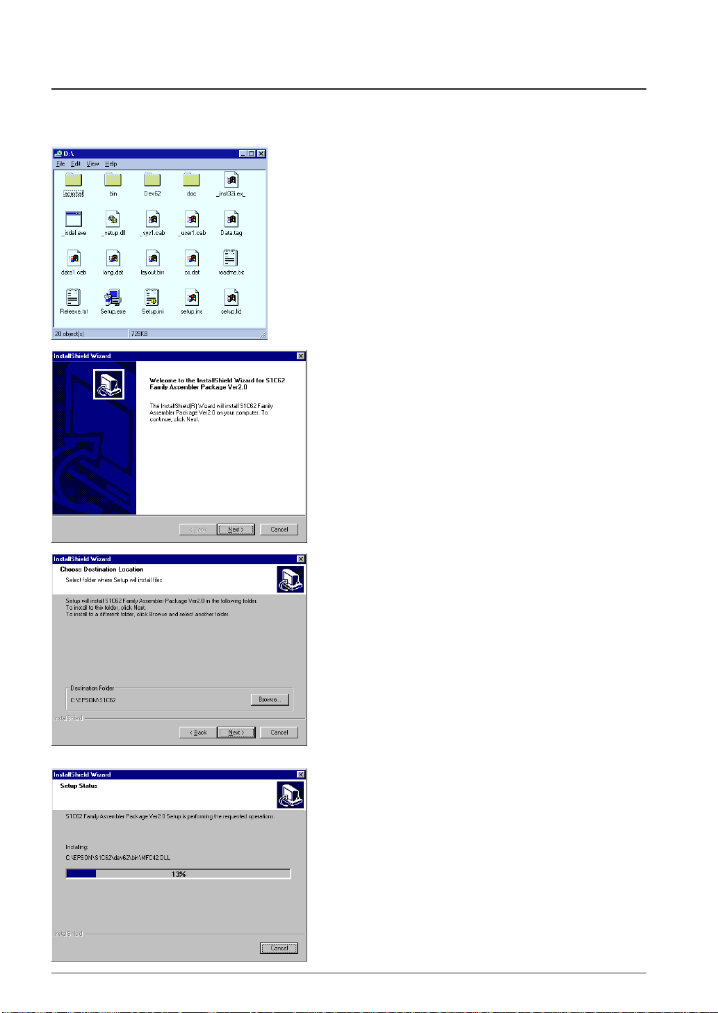
The supplied CD-ROM contains the installer (Setup.exe) that installs the tools.
To install the tools
(1) Start up Windows
When Windows has already activated, terminate all
the programs activated.
(2) Insert the CD-ROM into the CD-ROM drive, and
display its contents.
(3) Start up the Setup.exe by double-clicking the icon.
Welcome
(4) Click [Next>] to continue installation.
®
95 or Windows NT®4.0.
Choose Destination Location
A dialog box appears for specifying the installation
directory.
(5) Click [Next>] if the default directory
"C:\EPSON\S1C62" is not changed to another
directory.
To install the tools to another directory
Open the [Choose Folder] dialog box by clicking
[Browse...] and then enter the path name or choose
directory. Close the dialog box by clicking [OK] and
then click [Next>].
The installation starts after this selection.
4 EPSON S5U1C62000A MANUAL
(S1C60/62 FAMILY ASSEMBLER PACKAGE)
Page 17
CHAPTER 2: INSTALLATION
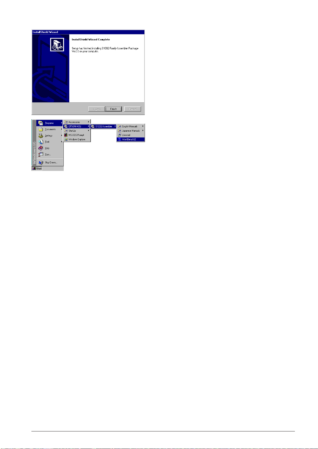
InstallShield Wizard Complete
(6) Click [Finish] to terminate the installer.
Program Menu
Installer registers the WorkBench62 icon to the program
menu.
To discontinue installation
The dialog boxes that appear during installation have a [Cancel] button. To discontinue installation,
click [Cancel] when a dialog box appears.
To uninstall the tools
Use [Add/Remove Programs] in the control panel to uninstall the tools.
S5U1C62000A MANUAL EPSON 5
(S1C60/62 FAMILY ASSEMBLER PACKAGE)
Page 18

CHAPTER 2: INSTALLATION
2.3 Directories and Files after Installation
The installer copies the following files in the specified directory (default is "C:\EPSON\S1C62"):
[Specified folder]
README.TXT ... ReadMe document
[bin]
WB62.EXE ... Work bench
AS62.EXE ... Assembler
LK62.EXE ... Linker
HX62.EXE ... Hex converter
DS62.EXE ... Disassembler
DB62.EXE ... Debugger
IEEE695.DLL ... Object format library for debugger
HEXLIB.DLL ... Hex file library for debugger
AS62.DLL ... Inline assembler for debugger
CORE62.DLL ... CPU library for debugger
ICE62.DLL ... ICE library for debugger
MSVCRT.DLL ... Run time library for work bench
OLEPRO32.DLL ... OLE library for work bench
SPAWNEX.EXE ... Child task library for work bench
[doc]
[English] ... Manual folder (English)
MANUAL_E.PDF ... S5U1C62000A Manual
DEV_MANUAL_E.PDF ... S1C60/62 Family Development Tool Manual
[Japanese] ... Manual folder (Japanese)
MANUAL_J.PDF ... S5U1C62000A Manual
DEV_MANUAL_J.PDF ... S1C60/62 Family Development Tool Manual
[dev62]
[bin]
WINFOG.EXE ... Function option generator
WINSOG.EXE ... Segment option generator
WINMDC.EXE ... Mask data checker
WINMLA.EXE ... Melody assembler
[62XXX] ... Model-dependent files for development tools
:
[dos]
:
... Model-dependent files for development tools (DOS version)
Note: Work bench assumes the above directory structure. Do not rename these folders or file names and
do not change the tree structure.
Online manual in PDF format
The online manuals are provided in PDF format, so Adobe Acrobat Reader Ver. 4.0 or later is needed
to read it.
6 EPSON S5U1C62000A MANUAL
(S1C60/62 FAMILY ASSEMBLER PACKAGE)
Page 19
CHAPTER 3: SOFTWARE DEVELOPMENT PROCEDURE
CHAPTER 3
S
OFTW ARE
D
EVELOPMENT PROCEDURE
This chapter outlines a basic development procedure.
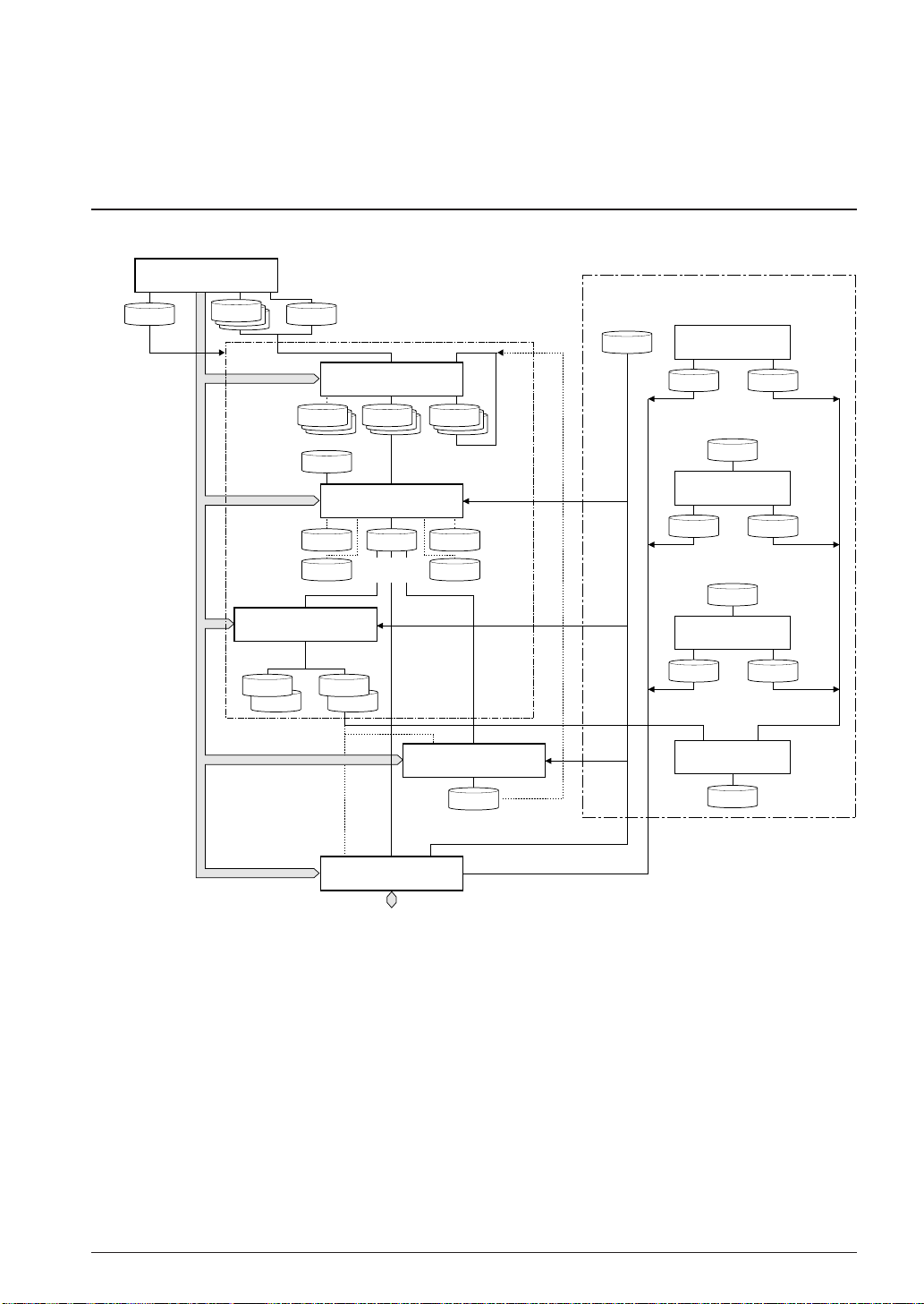
3.1 Software Development Flo w
Figure 3.1.1 represents a flow of software development work.
Work Bench
wb62
hx62
file.CM
file.SYMSymbol file
file.MAP file.XRFLink map file
Intel-HEX
format files
fileL.HEX
or
Assembly
source file(s)
fileH.HEX
Assembler
as62
file.Ofile.LST
Object
file(s)
Linker
lk62
file.ABS
Absolute
object file
file.MS
Preprocessed
source file(s)
file.ALS
Absolute
list file
Cross
reference
file
Make
file.MAK file.DAT
file
file.S
command file
Motorola-S
format files
or
Assembly
list file(s)
Linker
HEX converter
file.HSA
file.LSA
Development tools for each model
file.par
Function Option
Generator fog62XX
fileF.HEX fileF.DOC
Function option
HEX file
Generator sog62XX
fileS.HEX
Segment option
HEX file
Melody Assembler
fileA.HEX
Melody
HEX file
Function option
document file
file.SEG
Segment Option
fileS.DOC
Segment option
document file
file.mel
mla62XX
fileA.DOC
document file
Segment option
source file
Melody
data file
Melody
Mask Data Checker
mdc62XX
Mask
file.PAn
data file
Debugger
db62
In-Circuit Emulator
Disassembler
ds62
file.MS
Disassembled
source file
Fig. 3.1.1 Software development flow
The work bench provides an integrated development environment from source editing to debugging.
Tools such as the assembler and linker can be invoked from the work bench. The tools can also be invoked individually from the DOS prompt.
Refer to the respective chapter for details of each tool.
The part indicated as "Development tools for each model" is not covered in this manual. For details, refer
to the tool manual associated with each specific model.
S5U1C62000A MANUAL EPSON 7
(S1C60/62 FAMILY ASSEMBLER PACKAGE)
Page 20
CHAPTER 3: SOFTWARE DEVELOPMENT PROCEDURE
3.2 Development Using W ork Bench
This section shows a basic development procedure using the work bench wb62.
Refer to Chapter 4, "Work Bench", for operation details.
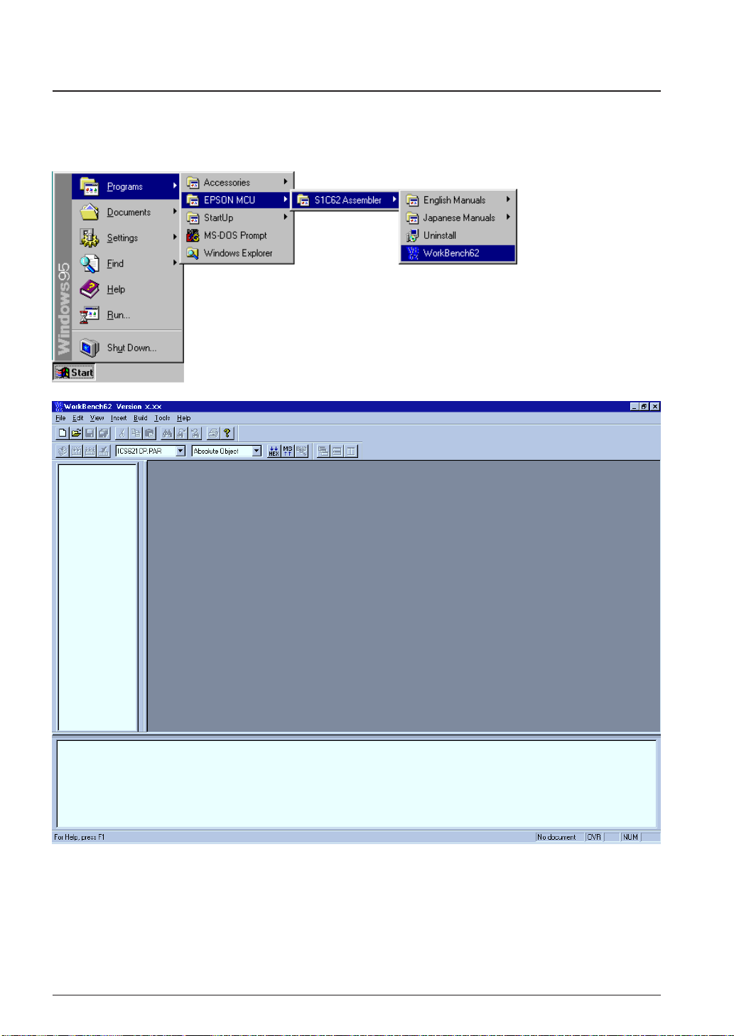
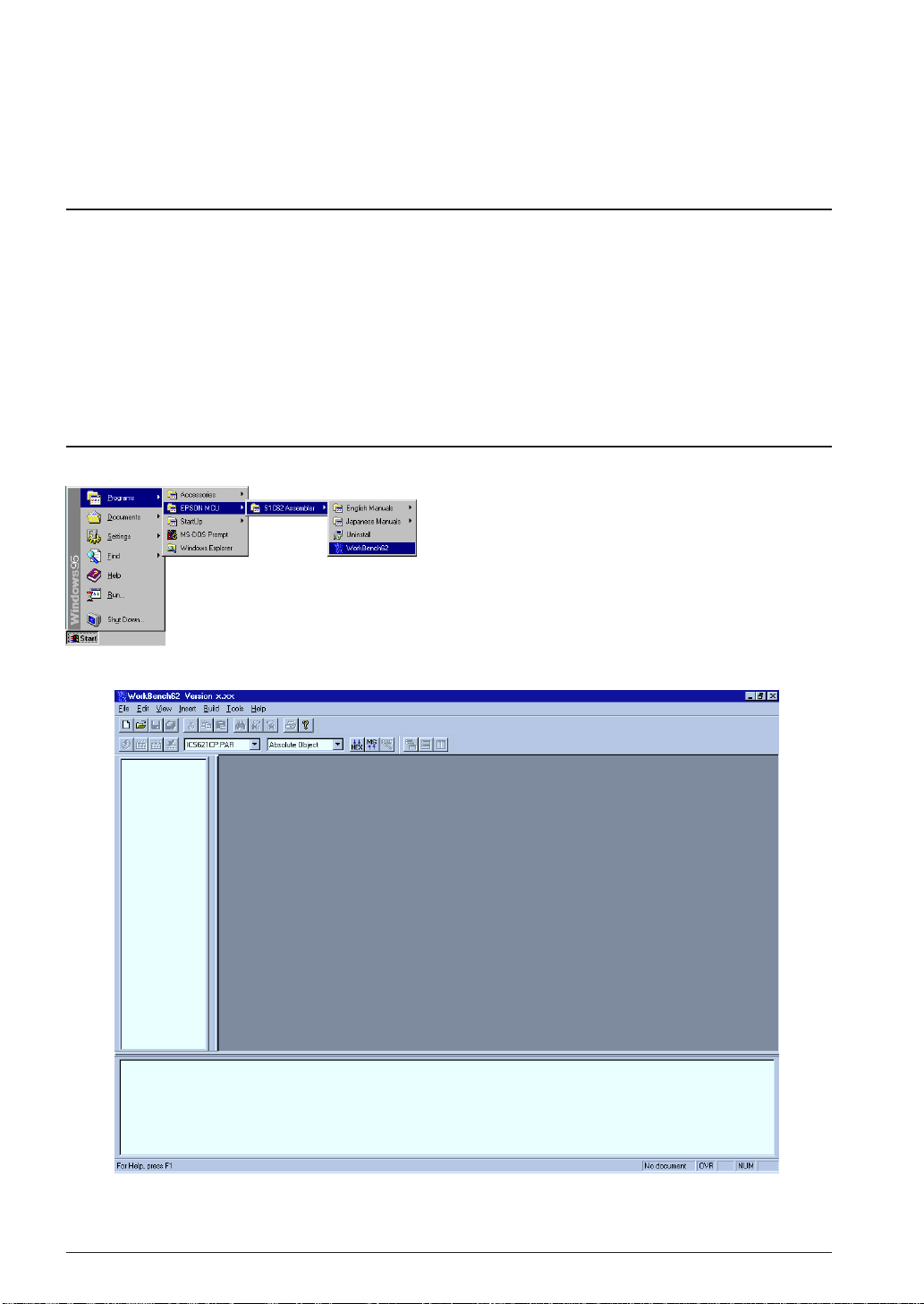
3.2.1 Starting Up the Work Bench
Start up the work bench by choosing "WorkBench62" from the program menu.
8 EPSON S5U1C62000A MANUAL
(S1C60/62 FAMILY ASSEMBLER PACKAGE)
Page 21
CHAPTER 3: SOFTWARE DEVELOPMENT PROCEDURE
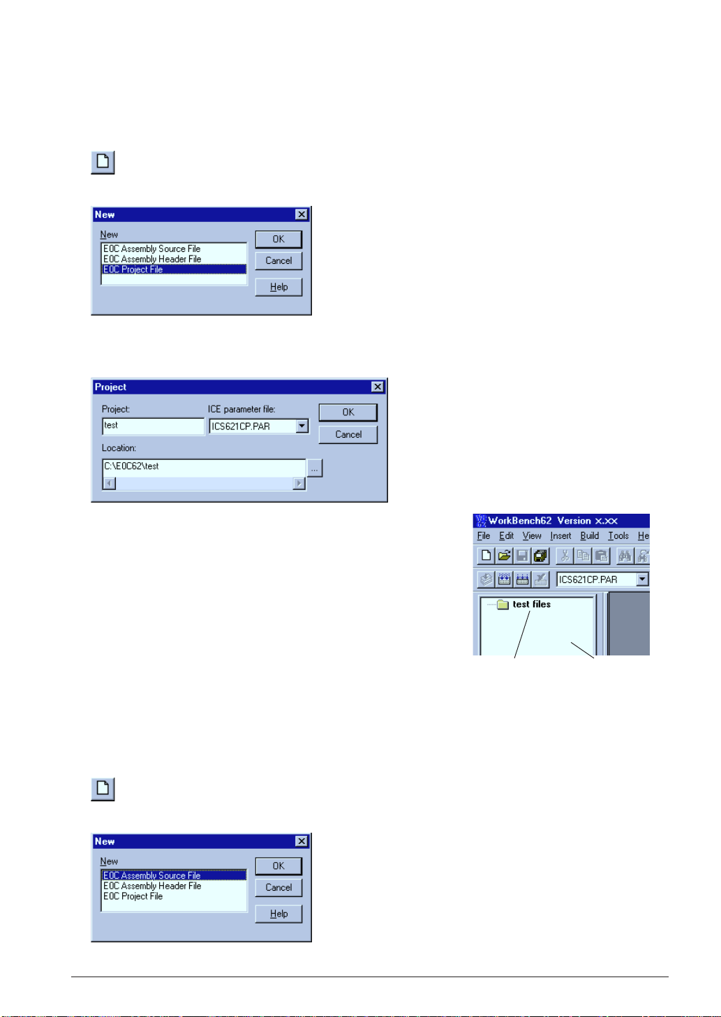
3.2.2 Creating a New Project
The work bench manages necessary file and tool setting information as a project.
First a new project file should be created.
1. Select [New] from the [File] menu (or click the [New] button).
[New] button
The [New] dialog box appears.
2. Select [E0C Project File] and click [OK].
The [Project] dialog box appears.
3. Enter a project name, select an ICE parameter file and select a
directory, then click [OK].
∗ The [ICE parameter file:] box lists the parameter files that exist
in the "dev62" directory.
The work bench creates a folder (directory) with the specified
project name as a work space, and puts the project file (.epj) into
the folder.
The specified project name will also be used for the absolute object
and other files.
Created project [Project] window
3.2.3 Editing Source Files
The work bench has an editor function. This makes it possible to edit source files without another editor.
To create a new source file:
1. Select [New] from the [File] menu (or click the [New] button).
[New] button
The [New] dialog box appears.
2. Select [E0C Assembly Source File] and click [OK].
S5U1C62000A MANUAL EPSON 9
(S1C60/62 FAMILY ASSEMBLER PACKAGE)
Page 22
CHAPTER 3: SOFTWARE DEVELOPMENT PROCEDURE
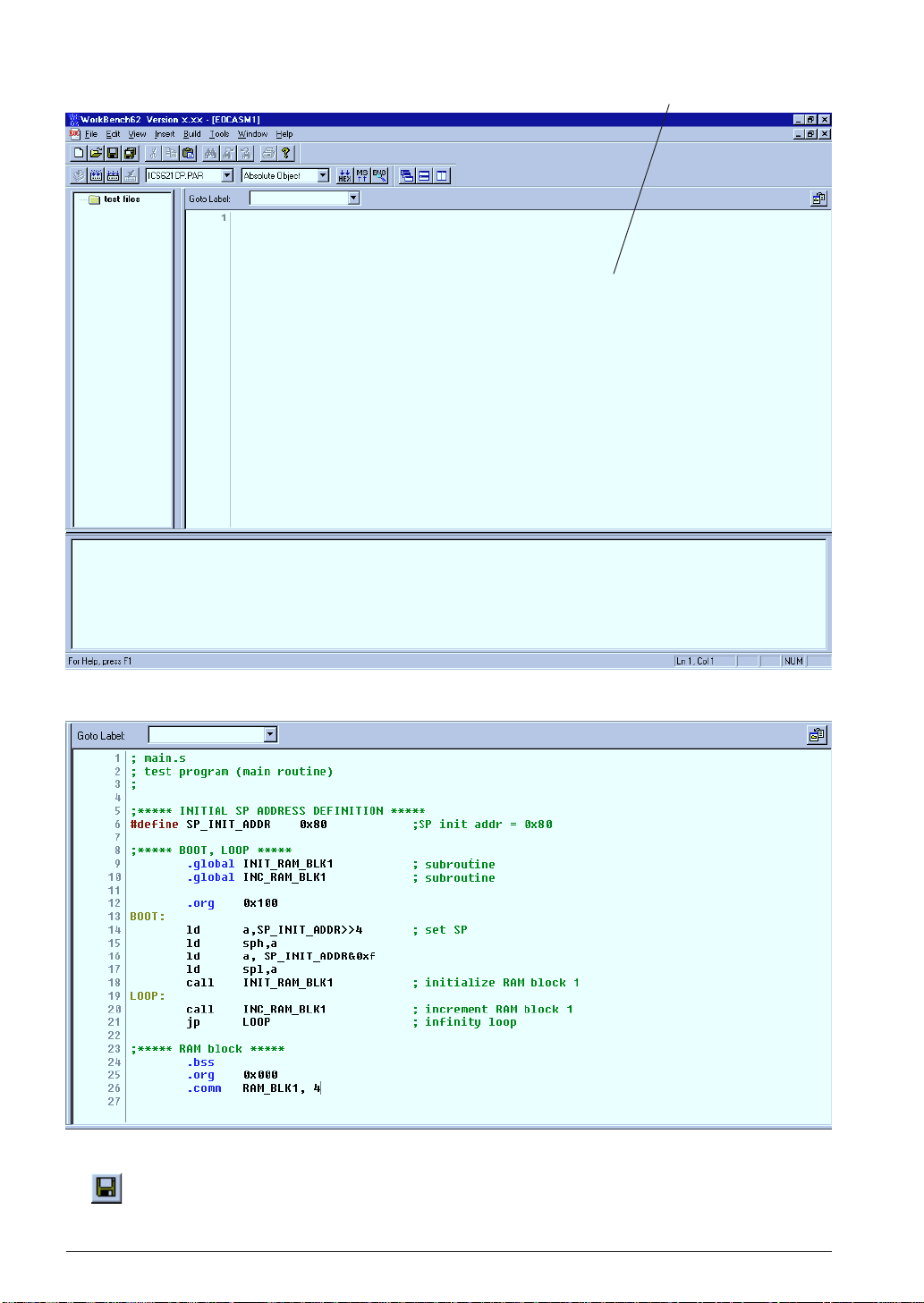
[Edit] windowA new edit window appears.
3. Enter source codes in the [Edit] window.
4. Save the source in a file by selecting [Save] from the [File] menu (or clicking the [Save] button).
[Save] button
10 EPSON S5U1C62000A MANUAL
(S1C60/62 FAMILY ASSEMBLER PACKAGE)
Page 23
CHAPTER 3: SOFTWARE DEVELOPMENT PROCEDURE
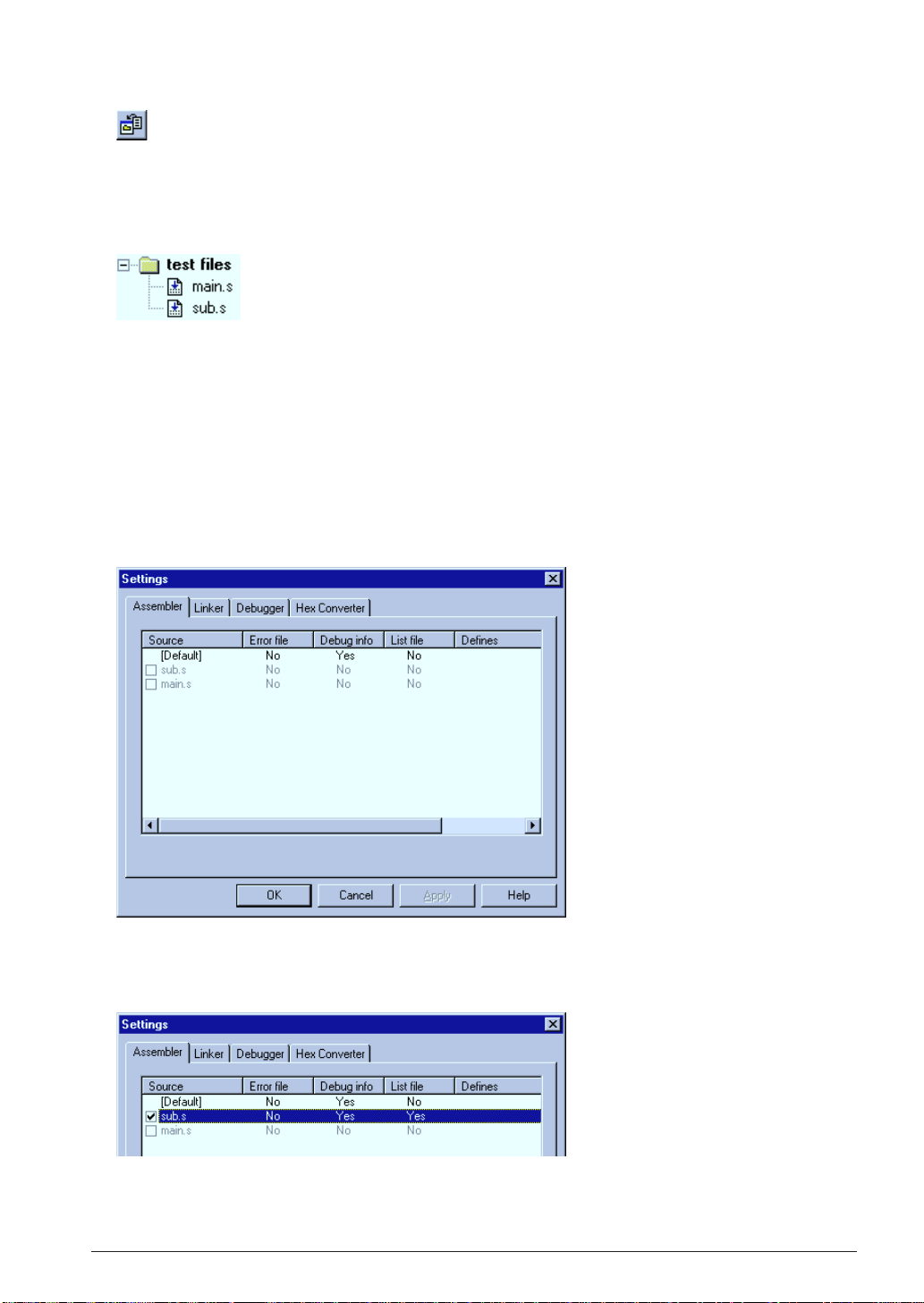
5. Click the [Insert into project] button on the [Edit] window.
[Insert into project] button
The created source file is added in the project.
To add existing source files, use [Files into project...] in the [Insert] menu. It can also be done by dragging
source files from Windows Explorer to the project window.
Create necessary source files and add them into the project.
Sample list in the [Project] window
The added source files are listed in the project window. Double-clicking a listed source file name opens
the edit window.
3.2.4 Configuration of Tool Options
The work bench supports all the start up options of each tool and they can be selected in a dialog box. A
make process for generating an executable object will be configured based on the settings.
In addition to option selection, command files for the linker and debugger can be configured here.
To set tool options:
1. Select [Setting...] from the [Build] menu.
A dialog box appears.
2. Configure options if necessary.
Check box items can be selected by clicking. Items in the list can be toggled or entered by doubleclicking.
Refer to Chapter 4, "Work Bench", for details of the [Settings] dialog box.
S5U1C62000A MANUAL EPSON 11
(S1C60/62 FAMILY ASSEMBLER PACKAGE)
Page 24
CHAPTER 3: SOFTWARE DEVELOPMENT PROCEDURE
3.2.5 Building an Executable Object
To make an executable object file:
1. Select [Build] from the [Build] menu (or click the [Build] button).
[Build] button
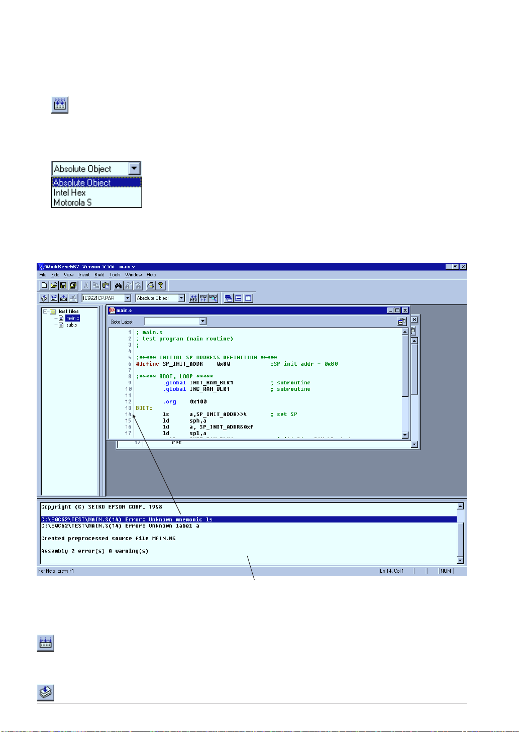
This will invoke the assembler and linker to create an executable object file. If a HEX file format (Intel
HEX or Motorola S) is selected by the [Output format] box, the HEX converter will be invoked after
linking. By default, an absolute object file in IEEE-695 format will be created.
[Output format] box
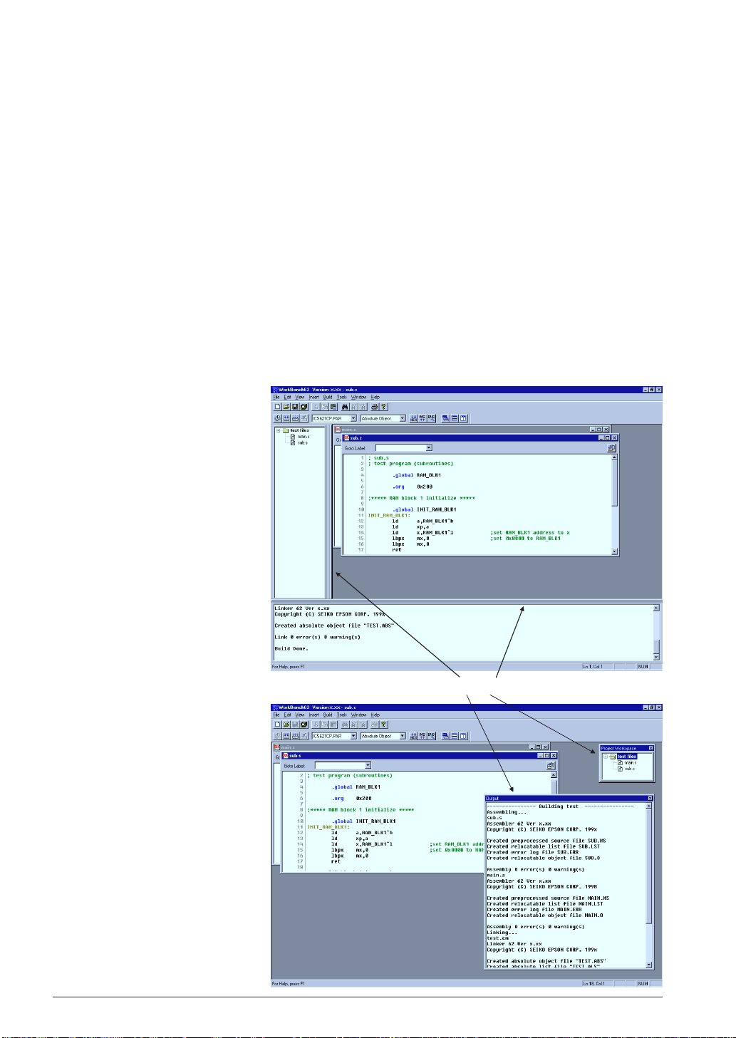
Messages delivered from each executed tool are displayed in the [Output] window. The work bench has a
tag-jump function that jumps to the source line in which an error has occurred by double-clicking a
source syntax error message that appears in the [Output] window. It opens the corresponding source
window if it is closed.
Linked with the corresponding source line
[Output] window
In the build task, a general make process is executed to update the least necessary files. To rebuild all the
files without the make function, select [Rebuild All] from the [Build] menu (or click the [Rebuild All]
button).
[Rebuild All] button
To invoke the assembler only to correct syntax errors, select [Assemble] in the [Built] menu (or click the
[Assemble] button).
[Assemble] button
12 EPSON S5U1C62000A MANUAL
(S1C60/62 FAMILY ASSEMBLER PACKAGE)
Page 25
CHAPTER 3: SOFTWARE DEVELOPMENT PROCEDURE
3.2.6 Debugging
To debug the executable object:
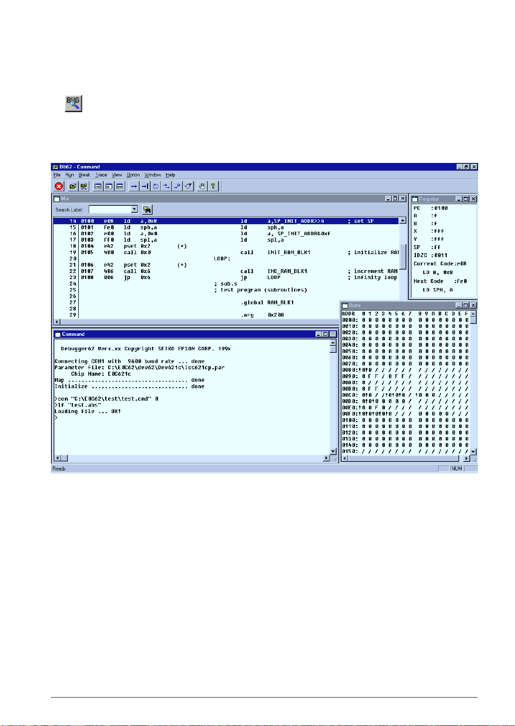
1. Select [Debug] from the [Build] menu (or click the [Debug] button).
[Debug] button
The debugger starts up with the specified ICE parameter file and then loads the executable object file.
Note: Make sure that the ICE is ready to debug before invoking the debugger. Refer to the ICE hardware
manual for settings and startup method of the ICE.
For the debugging functions and operations, refer to Chapter 9, "Debugger".
S5U1C62000A MANUAL EPSON 13
(S1C60/62 FAMILY ASSEMBLER PACKAGE)
Page 26
CHAPTER 4: WORK BENCH
CHAPTER 4WORK BENCH
This chapter describes the functions and operating method of the Work Bench wb62.
4.1 Features
The Work Bench wb62 provides an integrated operating environment ranging from editing source files to
debugging. Its functions and features are summarized below:
• Source edit function that supports copy/paste, find/replace, print, label jump and tag jump from error
messages.
• Allows simple management of all necessary files and information as a project.
• General make process to invoke necessary tools and to update the least necessary files.
• Supports all options of the assembler, linker, HEX converter, disassembler and debugger.
•Windows GUI interface for simple operation.
4.2 Starting Up and Terminating the Work Bench
To start up the work bench
Choose "WorkBench62" from the [Program] menu to
start up the work bench.
∗ If "WorkBench62" is not registered in the [Program]
menu, it means that the installation was not successful. Therefore, reinstall the tools by referring to
Chapter 2, "Installation".
When the work bench starts up, the window shown
below appears.
To terminate the work bench
Select [Exit] from the [File] menu.
14 EPSON S5U1C62000A MANUAL
(S1C60/62 FAMILY ASSEMBLER PACKAGE)
Page 27
4.3 Work Bench Windows
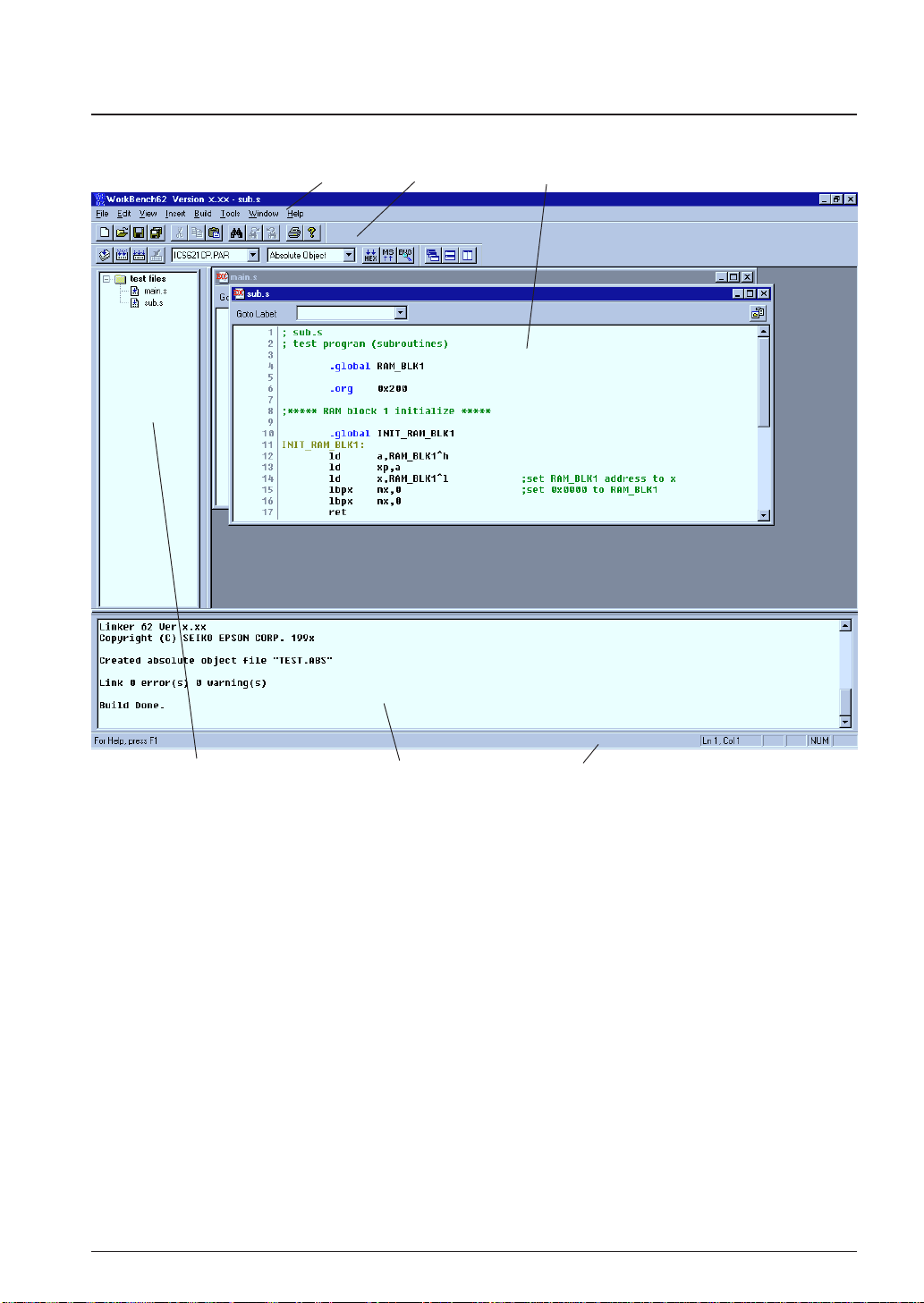
4.3.1 Windo w Configuration
Menu bar Toolbar [Edit] window
CHAPTER 4: WORK BENCH
[Project] window [Output] window Status bar
The work bench has three types of windows: [Edit] window, [Project] window and [Output] window.
[Edit] window
This window is used for editing a source file. A standard text file can also be displayed in this window. Two or more windows can be opened in the edit window area.
When an E0C62 assembly source file is opened, the source is displayed with in colors according to the
contents.
S1C62 instructions: Black
Preprocess (#) pseudo-instructions: Dark brown
Assemble (.) pseudo-instructions: Blue
Labels: Light brown
Comments: Green
[Project] window
This window shows the currently opened work space folder and lists all the source files in the project,
with a structure similar to Windows Explorer.
Double-clicking a source file icon opens the source file in the [Edit] window.
S5U1C62000A MANUAL EPSON 15
(S1C60/62 FAMILY ASSEMBLER PACKAGE)
Page 28
CHAPTER 4: WORK BENCH
[Output] window
This window displays the messages delivered from the executed tools in a build or assemble process.
Double-clicking a syntax error message with a source line number displayed in this window activates
or opens the [Edit] window of the corresponding source so that the source line in which the error has
occurred can be viewed.
Menu bar
Refer to Section 4.5.
Toolbar
Refer to Section 4.4.
Status bar
Shows help messages when the mouse cursor is placed on a menu item or a button.
It also indicates the cursor position in the [Edit] window, Key lock status (Num lock, Caps lock, Scroll
lock).
4.3.2 Windo w Manipulation
Resizing the windows
Each window area can be
resized by dragging the window boundary. The size
information is saved when the
work bench is terminated. So
the same window layout will
appearat the next time the work
bench starts up.
←| |→
←| |→
Double click
Floating and docking the
[Project] and [Output]
window
The [Project] window and the
[Output] window can be made
a floating window by doubleclicking the window boundary
and the floating window can be
moved and resized in the work
bench window. The floating
window will be restored to a
docking window by double
clicking the window's title bar
or dragging the title bar
towards an edge of the work
bench window.
16 EPSON S5U1C62000A MANUAL
(S1C60/62 FAMILY ASSEMBLER PACKAGE)
Page 29
CHAPTER 4: WORK BENCH
Closing the [Project] and [Output] window
The [Project] window and the [Output] window can be closed by selecting [Project Window] and
[Output Window] from the [View] menu, respectively. To open them, select the menu items again.
Maximizing the [Edit] window area
The [Edit] window area can be
maximized to the full screen size by
selecting [Full Screen] from the
[View] menu. All other windows
and toolbars are hidden behind the
[Edit] window area.
To return it to the normal display,
click the button that appears on the
screen. This button can be moved
anywhere in the screen by dragging
its title bar. Pressing the [ESC] key
also returns the window to the
normal display.
Opening/Closing [Edit] windows
An [Edit] window opens when a source file (text file) is loaded using a menu, button or a file icon in
the [Project] window, or when a new source is created.
[Edit] windows close by clicking the [Close] box of each window or selecting [Close] from the [File]
menu.
When a project file is saved, the [Edit] window information (files opened, size and location) is also
saved. So the next time the project opens, editing can begin in the saved condition.
Arrangement of the [Edit] windows
The [Edit] windows being opened can be arranged similar to standard Windows applications.
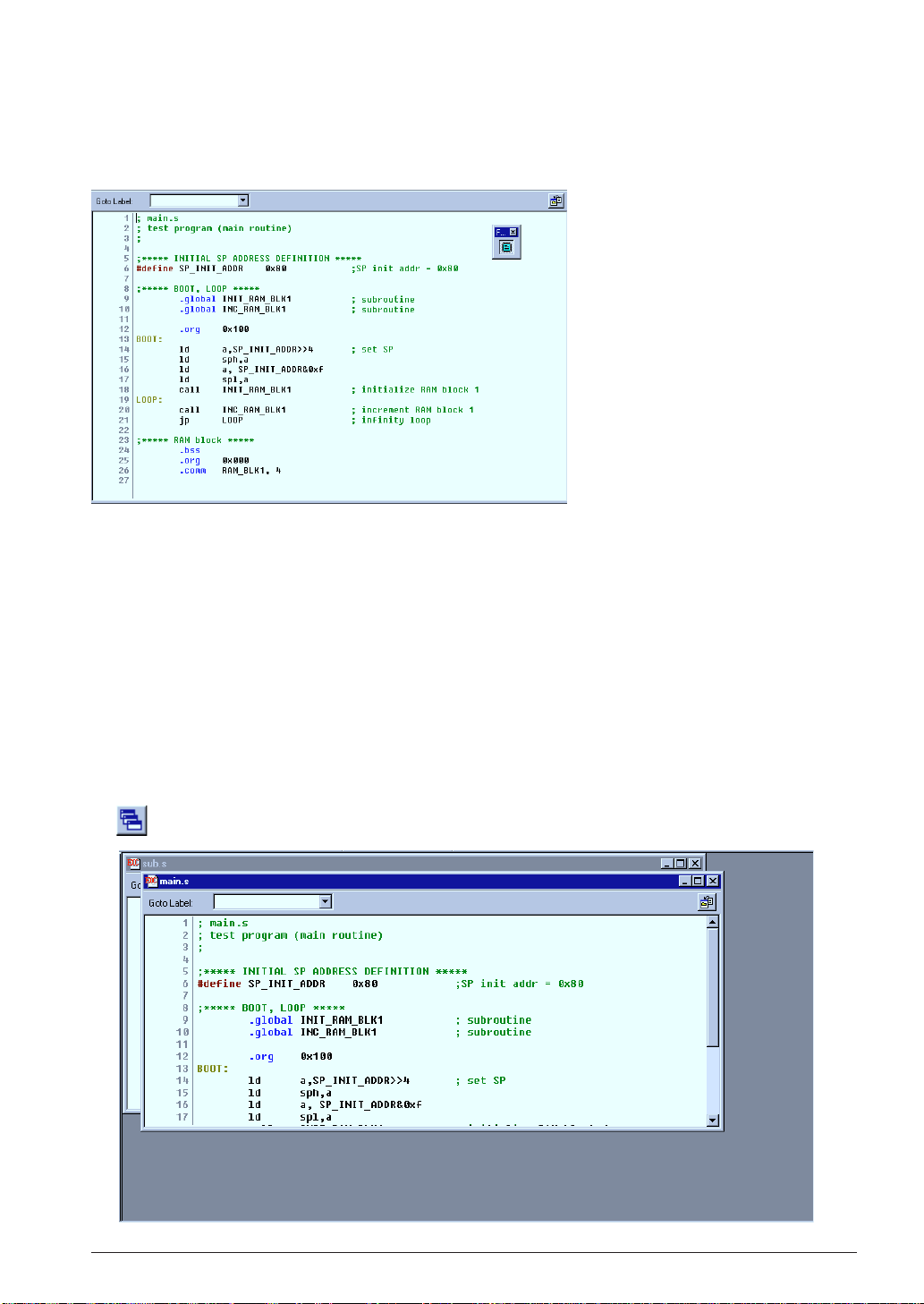
1Cascade windows
Select [Cascade] from the [Window] menu or click the [Cascade Windows] button.
[Cascade Windows] button
S5U1C62000A MANUAL EPSON 17
(S1C60/62 FAMILY ASSEMBLER PACKAGE)
Page 30
CHAPTER 4: WORK BENCH
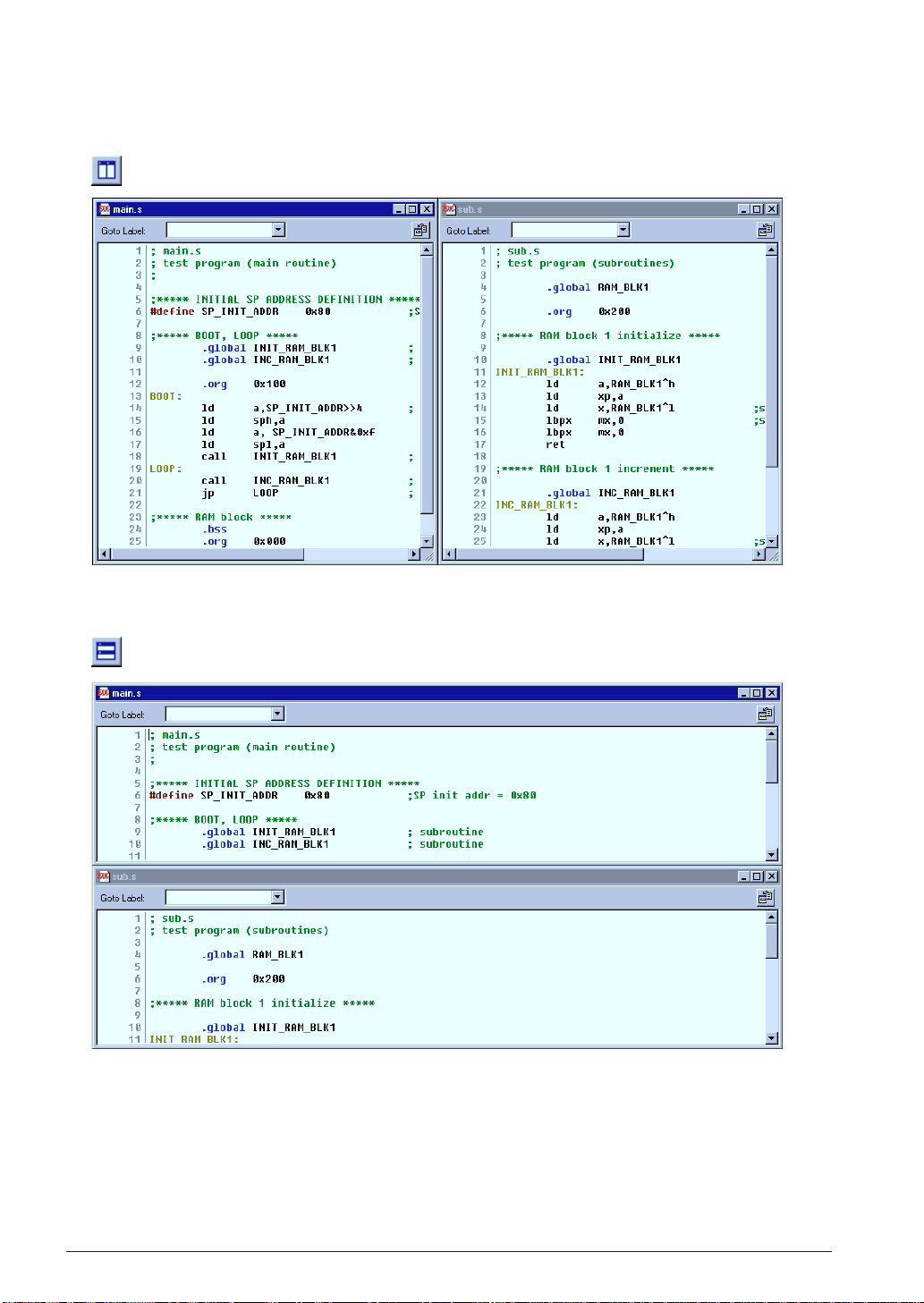
2Tile windows
To tile windows vertically, select [Tile Vertically] from the [Window] menu or click the [Tile Vertically]
button.
[Tile Vertically] button
To tile windows horizontally, select [Tile Horizontally] from the [Window] menu or click the [Tile
Horizontally] button.
[Tile Horizontally] button
18 EPSON S5U1C62000A MANUAL
(S1C60/62 FAMILY ASSEMBLER PACKAGE)
Page 31

CHAPTER 4: WORK BENCH
3Maximizing an [Edit] window
Click the [Maximize] button on the window title bar. The window will be maximized to the [Edit]
window area size and other [Edit] windows will be hidden behind the active window.
4Minimizing an [Edit] window
Click the [Minimize] button on the window title bar. The window will be minimized as a window
icon. The minimized icons can be arranged at the bottom of the [Edit] window area by selecting
[Arrange Icons] from the [Window] menu.
5Moving and resizing an [Edit] window
The [Edit] window allows changing of its location and its size in the same way as the standard
Windows applications if it is not maximized.
Switching active [Edit] window
Click the window to be activated if it can be viewed. Otherwise, select the window name (source file
name) from the currently-opened window list in the [Window] menu.
Scrolling display contents
A standard scroll bar appears if the display contents exceed the display size of a window. Use it to
scroll the display contents. The arrow keys can also be used.
Showing and hiding the status bar
The status bar can be shown or hidden by selecting [Status Bar] from the [View] menu.
S5U1C62000A MANUAL EPSON 19
(S1C60/62 FAMILY ASSEMBLER PACKAGE)
Page 32

CHAPTER 4: WORK BENCH
4.4 Toolbar and Buttons
Tree types of toolbars have been implemented in the work bench: standard toolbar, build toolbar and
window tool bar.
Standard toolbar
Build toolbar Window toolbar
4.4.1 Standard Toolbar
This toolbar has the following standard buttons:
[New] button
Creates a new document. A dialog box will appear allowing selection from among three document
types: E0C62 assembly source, E0C62 assembly header and project.
[Open] button
Opens a document. A dialog box will appear allowing selection of the file to be opened.
[Save] button
Saves the document in the active [Edit] window to the file. The file will be overwritten.
This button becomes inactive if no [Edit] window is opened.
[Save All] button
Saves the documents of all [Edit] windows and the project information to the respective files.
[Cut] button
Cuts the selected text in the [Edit] window to the clipboard.
[Copy] button
Copies the selected text in the [Edit] window to the clipboard.
[Paste] button
Pastes the text copied on the clipboard to the current cursor position in the [Edit] window or
replaces the selected text with the copied text.
[Find] button
Finds the specified word in the active [Edit] window. A dialog box will appear allowing specification of the word to be found and a search condition.
[Find Next] button
Finds next target word towards the end of the file.
[Find Previous] button
Finds next target word towards the beginning of the file.
[Print] button
Prints the document in the active [Edit] window. A standard print dialog will appear allowing a
specific print condition.
[Help] button
Displays a dialog box showing the version of the work bench.
20 EPSON S5U1C62000A MANUAL
(S1C60/62 FAMILY ASSEMBLER PACKAGE)
Page 33

CHAPTER 4: WORK BENCH
4.4.2 Build Toolbar
This tool bar has the following buttons and list boxes used to build a project:
[Assemble] button
Assembles the assembly source in the active [Edit] window. This button becomes active only when
the active [Edit] window shows an assembly source file.
[Build] button
Builds the currently opened project using a general make process.
[Rebuild All] button
Builds the currently opened project. All the source files will be assembled regardless of whether
they are updated or not.
[Stop Build] button
Stops the build process being executed. This button becomes active only while a build process is
being executed.
[ICE Parameter] pull-down list box
Selects the ICE parameter file for the model being developed. In this box, all the
ICE parameter files that exist in the "dev62" directory are listed.
[Output Format] pull-down list box
Selects an executable object file format. Three types of formats are available:
IEEE-695 absolute object format, Intel HEX format and Motorola S format. The
build process will generate an executable object in the format selected here.
[HEX Convert] button
Invokes the HEX converter to convert an absolute object into an Intel HEX object or a Motorola S
object. A dialog box will appear allowing selection of an absolute object and options of the HEX
converter.
[Disassemble] button
Invokes the disassembler to disassemble an absolute object. A dialog box will appear allowing
selection of an absolute object and options of the disassembler.
[Debug] button
Invokes the debugger with the specified ICE parameter file.
4.4.3 Windo w T oolbar
This tool bar has the following buttons used in window manipulation:
[Cascade] button
Cascades the opened [Edit] windows.
[Tile Horizontally] button
Tiles the opened [Edit] window horizontally.
[Tile Vertically] button
Tiles the opened [Edit] window vertically.
S5U1C62000A MANUAL EPSON 21
(S1C60/62 FAMILY ASSEMBLER PACKAGE)
Page 34

CHAPTER 4: WORK BENCH
4.4.4 Toolbar Manipulation
Hiding and showing toolbars
Each toolbar can be hidden if not needed. Select the toolbar name from the [View] menu. This operation toggles between hiding and showing the toolbar.
Changing the toolbar location
Toolbars can be moved to another location in the toolbar area by dragging them. If a toolbar is moved
out of the toolbar area, it will be changed to a window.
4.4.5 [Insert into project] Button on a [Edit] Window
[Insert into project] button
When a source file (.s, .ms or .dat) is opened, the [Insert into project] button appears on the [Edit] window. It can be used to insert the source file into the current opened project.
For other file types, the [Edit] window opens without the [Insert into project] button.
22 EPSON S5U1C62000A MANUAL
(S1C60/62 FAMILY ASSEMBLER PACKAGE)
Page 35

4.5 Menus
4.5.1 [File] Menu
CHAPTER 4: WORK BENCH
[New...] ([Ctrl]+[N])
Creates a new document. A dialog box will appear allowing selection
from among three document types: E0C62 assembly source, E0C62
assembly header and project.
[Open...] ([Ctrl]+[O])
Opens a document. A dialog box will appear allowing selection of the
file to be opened.
[Close]
Closes the active [Edit] window. This menu item appears when an
[Edit] window becomes active.
[Open Workspace...]
Opens a project. A dialog box will appear allowing selection of the
project to be opened.
The file names listed in this menu
are recently used source and
project files. Selecting one opens
the file.
[Close Workspace]
Closes the currently opened project. This menu item becomes inactive
if no project is opened.
[Save] ([Ctrl]+[S])
Saves the document in the active [Edit] window to the file. The file
will be overwritten. This menu item appears when an [Edit] window
becomes active.
[Save As...]
Saves the document in the active [Edit] window with another file
name. A dialog box will appear allowing specification of a save
location and a file name. This menu item appears when an [Edit]
window becomes active.
[Save All]
Saves the documents of all [Edit] windows and the project information
to the respective files.
[Print...] ([Ctrl]+[P])
Prints the document in the active [Edit] window. A standard [print]
dialog box will appear allowing a specific print condition. This menu
item appears when an [Edit] window becomes active.
[Print Preview]
Displays a print image of the document in the active [Edit] window.
This menu item appears when an [Edit] window becomes active.
[Page Setup...]
Displays a dialog box for selecting paper and printer.
S5U1C62000A MANUAL EPSON 23
(S1C60/62 FAMILY ASSEMBLER PACKAGE)
Page 36

CHAPTER 4: WORK BENCH
4.5.2 [Edit] Menu
[Undo] ([Ctrl]+[Z])
Undoes the previous executed operation in the [Edit] window.
[Cut] ([Ctrl]+[X])
Cuts the selected text in the [Edit] window to the clipboard.
[Copy] ([Ctrl]+[C])
Copies the selected text in the [Edit] window to the clipboard.
[Paste] ([Ctrl]+[V])
Pastes the text copied on the clipboard to the current cursor position in the
[Edit] window or replaces the selected text with the copied text.
[Select All] ([Ctrl]+[A])
Selects all text in the active [Edit] window.
[Find...] ([Ctrl]+[F])
Finds the specified word in the active [Edit] window. A dialog box will
appear allowing specification of the word to be found and a search condition.
[Replace] ([Ctrl]+[H])
Replaces the specified words in the active [Edit] window with one another. A
dialog box will appear allowing specification of the words.
4.5.3 [View] Menu
[Go T o] ([Ctrl]+[G])
Jumps to the specified line or label in the active [Edit] window. A dialog box
will appear allowing specification of a line number or a label name.
[Standard Bar]
Shows or hides the standard toolbar.
[Status Bar]
Shows or hides the status bar located at the bottom of the work bench
window.
[Output Window]
Opens or closes the [Output] window.
[Project Window]
Opens or closes the [Project] window.
[Build Bar]
Shows or hides the build toolbar.
[Window Bar]
Shows or hides the window toolbar.
[Full Screen]
Maximizes the [Edit] window area to the full screen size.
24 EPSON S5U1C62000A MANUAL
(S1C60/62 FAMILY ASSEMBLER PACKAGE)
Page 37

4.5.4 [Insert] Menu
4.5.5 [Build] Menu
CHAPTER 4: WORK BENCH
[File...]
Inserts the specified file to the current cursor position in the [Edit]
window or replaces the selected text with the contents of the
specified file. A dialog box will appear allowing selection of the file
to be inserted.
[Files into project...]
Adds the specified source file in the currently opened project. A
dialog box will appear allowing selection of the file to be added.
[Assemble] ([Ctrl]+[F7])
Assembles the assembly source in the active [Edit] window. This
menu item becomes active only when the active [Edit] window
shows an assembly source file.
[Build] ([F7])
Builds the currently opened project using a general make process.
[Rebuild All]
Builds the currently opened project. All the source files will be
assembled regardless of whether they are updated or not.
4.5.6 [Tools] Menu
[Stop Build] ([Ctrl]+[Break])
Stops the build process being executed. This button become active
only while a build process is being executed.
[Debug] ([F5])
Invokes the debugger with the specified ICE parameter file.
[Settings...] ([Alt]+[F7])
Displays a dialog box for selecting tool options.
[ICE parameter file...]
Displays a dialog box for selecting an ICE parameter file.
[Output Format...]
Displays a dialog box for selecting an executable object file format.
Three types of formats are available: IEEE-695 absolute object
format, Intel HEX format and Motorola S format. The build process
will generate an executable object in the format selected here.
[HEX Converter...]
Invokes the HEX converter to convert an absolute object into an
Intel HEX object or Motorola S object. A dialog box will appear
allowing selection of an absolute object and options for the HEX
converter.
[Disassembler...]
Invokes the disassembler to disassemble an absolute object. A
dialog box will appear allowing selection of an absolute object and
options for the disassembler.
S5U1C62000A MANUAL EPSON 25
(S1C60/62 FAMILY ASSEMBLER PACKAGE)
Page 38

CHAPTER 4: WORK BENCH
4.5.7 [Window] Menu
This menu appears when an [Edit] window is opened.
[Cascade]
Cascades the opened [Edit] windows.
[Tile Horizontally]
Tiles the opened [Edit] window horizontally.
[Tile Vertically]
Tiles the opened [Edit] window vertically.
The currently opened
document file names are
listed in this menu.
Selecting one activates
the [Edit] window.
4.5.8 [Help] Menu
[Arrange Icons]
Arranges the minimized [Edit] window icons at the bottom of the [Edit] window area.
[Close All]
Closes all the [Edit] windows opened.
[About WB62...]
Displays a dialog box showing the version of the work bench.
26 EPSON S5U1C62000A MANUAL
(S1C60/62 FAMILY ASSEMBLER PACKAGE)
Page 39

CHAPTER 4: WORK BENCH
4.6 Project and Work Space
The work bench manages a program development task using a work space folder and a project file that
contains file and other information necessary for invoking the development tools.
4.6.1 Creating a New Project
A new project file can be created by the following procedure:
1. Select [New] from the [File] menu or click the [New] button.
[New] button
The [New] dialog box appears.
2. Select [E0C Project File] and click [OK].
The [Project] dialog box appears.
3. Enter a project name, select an ICE parameter file and select a directory, then click [OK].
∗ The [ICE parameter file:] box lists the parameter files that exist in the "dev62" directory.
The work bench creates a folder (directory) with the specified project name as a work space, and puts the
project file (.epj) into the folder.
If a folder which has the same name as that of a specified one already exists in the specified location, the
work bench uses the folder as the work space. Thus you can specify a folder in which sources are created.
The specified project name will also be used for the absolute object and other files.
S5U1C62000A MANUAL EPSON 27
(S1C60/62 FAMILY ASSEMBLER PACKAGE)
Page 40

CHAPTER 4: WORK BENCH
4.6.2 Inserting Sources into a Project
The sources created must be inserted into the project.
To insert a source into a project, use one of the four methods shown below:
1. [Insert | Files into project...] menu item
A dialog box appears when this menu item is selected.
Choose a source file from the list box and then click [Open].
2. [File | Open...] menu item or [Open] button
[Open] button
A dialog box appears when this menu item or button is selected.
Choose a source file from the list box and select the [Into project] button, then click [Open].
3. [Insert into project] button on the [Edit] window
[Insert into project] button
When the source file has been opened, click the [Insert into project] button on the [Edit] window. Do
not forget to save the source to the file before inserting into the project.
4. Dragging source files on the [Project] window
Drag source files from Windows Explorer to the [Project] window. These files will be added to the
current project.
When a source file is inserted into the project, the source file name appears in the [Project] window.
Removing a source from the project
To remove a source file from the project, select the source in the [Project] window and then press the
[Delete] key. This removes only the source information, and does not delete the actual source file.
28 EPSON S5U1C62000A MANUAL
(S1C60/62 FAMILY ASSEMBLER PACKAGE)
Page 41

CHAPTER 4: WORK BENCH
4.6.3 [Project] Window
The [Project] window shows the work space folder and the source files included in the project that has
been opened.
When a source file icon is double-clicked, the source file will be opened or the corresponding [Edit]
window will be activated.
When the folder icon or a source file icon is double-clicked with the right
mouse button, a shortcut menu including the available build menu items
appears.
Note: Note that the list in the [project] window is not the actual directory
structure.
Sources of the project in other folders than the work space folder
are also listed as they exist in the work space folder.
Shortcut menu in the [Project] window
4.6.4 Opening and Closing a Project
To open a project, select [Open WorkSpace...] from the [File] menu.
A dialog box appears allowing selection of a project file.
The work bench allows only one project to be opened at a time. So if a project has been opened, it will be
closed when another project is opened. At this time, a dialog box appears to select whether the current
project file is to be saved or not if it has not already been saved after a modification.
The project file can also be opened by selecting [Open] from the [File] menu or clicking the [Open] button.
In this case, choose the file type as S1C Project Files (*.epj) in the file open dialog box.
To close the currently opened project file, select [Close WorkSpace] from the [File] menu. At this time, a
dialog box appears to select whether the current project file is to be saved or not if it has not already been
saved after a modification. If [Yes] (save) is selected in this dialog box, all the modification items including sources, tool settings and window configuration will be saved.
S5U1C62000A MANUAL EPSON 29
(S1C60/62 FAMILY ASSEMBLER PACKAGE)
Page 42

CHAPTER 4: WORK BENCH
4.6.5 Files in the Work Space Folder
The work bench generates the following files in the work space folder:
<file>.epj Project file
This file contains the project information.
<file>.cm Linker command file
This file is generated when a build task is started, and is used by the linker to generate an absolute
object file.
Example:
; WorkBench62 Generated
; Friday, May 01, 1998
"C:\E0C62\dev62\Dev621c\Ics621cp.par" ;ICE parameter file
-o "test.abs" ;output file : absolute object
; linked object file(s)
"sub.o"
"main.o"
The contents vary according to the source files included in the project and the linker option setting.
<file>.cmd Debugger startup command file
This file is generated when a build task is started, and is used by the debugger to execute the command in this file when it is started up.
Example:
lf "test.abs"
The work bench generates this file so that the executable file according to the format selection is
loaded when the debugger starts up.
<file>.mak "make" file for build task
This file is generated when a build task is started, and is used for the build process in the work bench.
Example:
# WorkBench62 Generated
# Friday, May 01, 1998
ASM = as62.exe
LINK = lk62.exe
HEX = hx62.exe
ASM_FLG = -g
LINK_FLG = -g
HEX_FLG = -e -b
ALL : test.abs
test.abs : test.cm sub.o main.o
$(LINK) $(LINK_FLG) test.cm
sub.o : C:\E0C62\test\sub.s
$(ASM) $(ASM_FLG) C:\E0C62\test\sub.s
main.o : C:\E0C62\test\main.s
$(ASM) $(ASM_FLG) C:\E0C62\test\main.s
This is a generic make file that contains macro setting and dependency list.
The following files are generated by the development tools during a build process:
<file>.o Relocatable object files (generated by the assembler)
<file>.abs Absolute object file (generated by the linker)
<file>h.hex, <file>l.hex Intel HEX files (generated by the Hex converter when this format is specified
in the work bench)
<file>.hsa, <file>.lsa Motorola S files (generated by the HEX converter when this format is speci-
fied in the work bench)
30 EPSON S5U1C62000A MANUAL
(S1C60/62 FAMILY ASSEMBLER PACKAGE)
Page 43

CHAPTER 4: WORK BENCH
4.7 Source Editor
The work bench has a source editor function. Sources can be created and modified in the [Edit] window.
4.7.1 Creating a New Source or Header File
To create a new source file:
1. Select [New] from the [File] menu or click the [New] button.
[New] button
The [New] dialog box appears.
2. Select [E0C Assembly Source File] and click [OK].
An [Edit] window appears.
[Edit] window
Enter source codes here.
Enter source codes in this window.
The [New] dialog box allows selection of the [E0C Header File]. Select it when creating a header file for
constant definitions.
S5U1C62000A MANUAL EPSON 31
(S1C60/62 FAMILY ASSEMBLER PACKAGE)
Page 44

CHAPTER 4: WORK BENCH
4.7.2 Loading and Saving Files
To load a source file:
1. Select [Open...] from the [File] menu or click the [Open] button.
[Open] button
The [Open] dialog box appears.
2. Choose a source file to be opened after selecting the file type (*.s, *.ms, *.dat) and click [OK].
An [Edit] window opens and shows the contents of the source file.
32 EPSON S5U1C62000A MANUAL
(S1C60/62 FAMILY ASSEMBLER PACKAGE)
Page 45

CHAPTER 4: WORK BENCH
To save the source:
1. Activate the [Edit] window of the source to be saved.
2. Select [Save as...] from the [File] menu.
The [Save As] dialog box appears.
3. Enter the file name and then click [OK].
When overwriting the source on the existing file, select [Save] from the [File] menu or click the [Save]
button.
[Save] button
To save all the source files opened and the project file, use the [File | Save All] menu item or the [Save
All] button.
[Save All] button
4.7.3 Edit Function
The source editor has general text editing functions similar to standard Windows applications.
Editing text
Basic text editing function is the same as general Windows applications.
Cut, copy and paste are supported in the [Edit] menu and with the toolbar buttons. These commands
are available only in the [Edit] window.
Undo can be selected from the [Edit] menu.
The tab stops are set at every 8 characters.
Find, replace and go to
Any words can be searched in the active [Edit] window.
Find
To find a word, select [Find...] from the [Edit] menu or click the [Find] button.
[Find] button
The [Find] dialog box appears.
S5U1C62000A MANUAL EPSON 33
(S1C60/62 FAMILY ASSEMBLER PACKAGE)
Page 46

CHAPTER 4: WORK BENCH
The controls in the dialog are as follows:
[Find what:] text box
Enter the word to be found in this text box. The specified word is maintained as the finding word
even if this dialog box is closed.
[Match whole word only] check box
If this option is selected, the work bench searches only the words that are completely matched
with the specified word. If not, only the part of word that matches the specified word will be
searched.
[Match case] check box
If this option is specified, a case-sensitive search is performed. If not, a case-insensitive search is
performed.
[Direction] option
If the [Up] radio button is selected, the specified word is searched toward to the beginning of the
file. If the [Down] radio button is selected, a search is performed toward to the end of the file.
[Find Next] button
Clicking this button starts searching the specified word. If the specified word is found, the [Edit]
window refreshes the display and highlights the word found.
[Cancel] button
Clicking this button closes the dialog box.
Once a word to be found is specified in the [Find] dialog box, the [Find Next] and [Find Previous]
buttons on the toolbar can be used for a forward or backward search.
[Find Next] button [Find Previous] button
Replace
To replace a word with another one, select [Replace] from the [Edit] menu.
The [Replace] dialog box appears.
The controls in the dialog are as follows:
[Find what:] text box
Enter the word to be found in this text box. If a word has been specified in the [Find] dialog box, it
appears in this box.
[Replace with:] text box
Enter the substitute word in this box.
[Match whole word only] check box
If this option is selected, the work bench searches only the words that are completely matched
with the specified word. If not, only the part of word that matches the specified word will be
searched.
[Match case] check box
If this option is specified, a case-sensitive search is performed. If not, a case-insensitive search is
performed.
34 EPSON S5U1C62000A MANUAL
(S1C60/62 FAMILY ASSEMBLER PACKAGE)
Page 47

CHAPTER 4: WORK BENCH
[Find Next] button
Clicking this button starts searching the specified word. If the specified word is found, the [Edit]
window refreshes the display and highlights the word found.
[Replace] button
By clicking this button after the specified word is found, it is replaced with the substitute word.
Then the work bench searches the next.
[Replace All] button
Replaces all the specified found words with the substitute word. Note that undo function cannot
be performed for this operation except for the last replaced word.
[Cancel] button
Clicking this button closes the dialog box.
Go to
You can go to any source line or any label position quickly.
To do this, select [Go To] from the [Edit] menu.
The [Go To] dialog box appears.
Going to a source line
1. Select "Line" in the [Go to what:] list box.
2. Type a line number in the [Enter Line Number] box and then click the [Go To] button.
Going to a label position
1. Select "Label" in the [Go to what:] list box.
The [Enter Line Number] box changes to the [Select Label] list box.
2. Select a label from the [Select Label] box and then click the [Go To] button.
The [Select Label] list box has a pull-down menu that contains the list of labels defined in the current
source file.
The [Edit] windows for source files (*.s, *.ms, *.dat) have the [Go To Label] list box similar to the
[Select Label] list box in the [Go To] dialog box. You can also go to a label position using this box.
Inserting a file
To insert a file such as a header file and another source at the cursor position of the current source,
select [File...] from the [Insert] menu.
A dialog box will appears allowing selection of the file to be inserted.
S5U1C62000A MANUAL EPSON 35
(S1C60/62 FAMILY ASSEMBLER PACKAGE)
Page 48

CHAPTER 4: WORK BENCH
Shortcut menu
The [Edit] window supports a short cut menu that appears by clicking the right mouse button on the
[Edit] window. It can also be done by pressing the [Short cut menu] key while the [Edit] window is
active if the key is available on the keyboard. It contains the editing menu items descried above, so
you can select an edit command using this menu.
4.7.4 Tag Jump Function
When assembler syntax errors occur during assembling, their error messages are displayed in the [Output] window. In this case, you can go to the source line in which an error has occurred by double-clicking
the error message in the [Output] window.
However, this function is available only when the error message contains a source line number.
Linked with the corresponding source line
36 EPSON S5U1C62000A MANUAL
(S1C60/62 FAMILY ASSEMBLER PACKAGE)
Page 49

CHAPTER 4: WORK BENCH
4.7.5 Printing
The document in the [Edit] window can be printed out.
The [Print...], [Print Preview] and [Page Setup...] commands are provided in the [File] menu. The [Print]
button can also be used. They have the same function as those of standard Windows application.
Select one after activating the [Edit] window of the document to be printed.
4.8 Build Task
By using the [Build] menu or [Build] toolbar, the assembler, linker, debugger, HEX converter and
disassembler can be executed from the work bench.
In the work bench, process to generate an executable object from the source files is called a build task.
For details of each development tool, refer to the respective chapter.
4.8.1 Preparing a Build Task
Before starting a build task, necessary source files should be prepared and tool options should be configured.
1. Create a new project. (Refer to Section 4.6.1.)
2. Select an ICE parameter file. (Refer to Section 4.6.1.)
3. Create source files and add them into the project. (Refer to Sections 4.7 and 4.6.2.)
4. Select tool options (Refer to Section 4.9.)
4.8.2 Building an Executable Object
To generate an executable object:
1. Open the project file.
2. Select an output format (absolute, Intel HEX or Motorola S) using the [Output Format] list box.
3. Select [Build] from the [Build] menu or click the [Build] button.
[Build] button
The work bench generates a make file according to the source files in the project and the tool options set
by the user. This file is used to control invocation of tools.
First, the make process invokes the assembler for each source file to be assembled. If the latest relocatable
object file exists in the work space, the corresponding source file is not assembled to reduce process time.
Next, the linker is invoked to generate an absolute object file. The linker command file used in this phase
is automatically generated.
If absolute object has been selected as the output format, the build task is completed at this phase. If Intel
HEX or Motorola S has been selected, the HEX converter will be invoked to generate an object in the
specified format.
To rebuild all files including the latest relocatable object files, select [Rebuild All] from the [Build] menu
or click the [Rebuild All] button.
[Rebuild All] button
The build task can be suspended by selecting [Stop Build] from the [Build] menu or clicking the [Stop
Build] button.
[Stop Build] button
S5U1C62000A MANUAL EPSON 37
(S1C60/62 FAMILY ASSEMBLER PACKAGE)
Page 50

CHAPTER 4: WORK BENCH
To invoke only the assembler, select [Assemble] from the [Build] menu or click the [Assemble] button
after activating the [Edit] window of the source to be assembled.
[Assemble] button
4.8.3 Debugging
To debug the generated executable file, select [Debug] from the [Build] menu or click the [Debug] button.
[Debug] button
The debugger starts up with the specified ICE parameter file and then loads the executable object by the
command file generated from the work bench.
This command file contains the command to load the specified type of an executable object to the
debugger. The contents of the command file can be edited in the [Settings] dialog box explained in
Section 4.9.
∗ When the building process is performed again after invoking the debugger, the debugger will reload
the object file if its window can be activated.
Refer to Chapter 9, "Debugger", for operating the debugger.
38 EPSON S5U1C62000A MANUAL
(S1C60/62 FAMILY ASSEMBLER PACKAGE)
Page 51

CHAPTER 4: WORK BENCH
4.8.4 Executing Other Tools
The HEX converter and disassembler can be invoked independently.
HEX converter
To invoke the HEX converter, select [HEX converter...] from the [Tools] menu or click the [HEX
convert] button.
[HEX convert] button
Then select an absolute object file to be converted in the [Hex data convert] dialog box.
This dialog box allows selection of the HEX converter options.
[ICE Parameter file:] list box
Select an ICE parameter file from the pull-down list.
[Output Format:] list box
Select an output format from between Intel HEX and Motorola S.
[Output error log file] check box
Select this option to generate the error log file of the HEX converter.
[Do not fill room with 0xFF] check box
Select this option when not filling the unused program area with 0xFF.
After selecting an absolute object and options, click the [Open] button. The HEX converter starts up
and converts the selected object into the specified format. The messages delivered from the HEX
converter are displayed in the [Output] window.
S5U1C62000A MANUAL EPSON 39
(S1C60/62 FAMILY ASSEMBLER PACKAGE)
Page 52

CHAPTER 4: WORK BENCH
Disassembler
To invoke the disassembler, select [Disassembler...] from the [Tools] menu or click the [Disassemble]
button.
[Disassemble] button
Then select the executable object file to be disassembled in the [Disassemble] dialog box.
This dialog box allows selection of the disassembler options.
[ICE Parameter file:] list box
Select an ICE parameter file from the pull-down list.
[Output error log file] check box
Select this option to generate the error log file of the disassembler.
[Output Option]
Select a character case option using the radio buttons.
When [Default] is selected, the disassembled source will be made with all labels in upper-case
characters and instructions in lower-case characters.
When [Upper case] is selected, the source will be made with upper-case characters only.
When [Lower case] is selected, the source will be made with lower-case characters only.
[Start address] box
Specify the address used for the first .org instruction in the disassembled source.
If this option is not specified, the disassembled source will begin with address 0.
After selecting an executable object and options, click the [Open] button. The disassembler starts up
and converts the selected object into the source file. The messages delivered from the disassembler are
displayed in the [Output] window.
40 EPSON S5U1C62000A MANUAL
(S1C60/62 FAMILY ASSEMBLER PACKAGE)
Page 53

CHAPTER 4: WORK BENCH
4.9 Tool Option Settings
The development tools have startup options that can be specified when invoking them.
These settings can be made in the [Settings] dialog box that appears by selecting [Settings...] from the
[Build] menu.
Click the tool name tab to view option settings of each tool.
Clicking the [OK] button updates option setting information in the project and then closes the dialog box.
To continue to select other tool options, click the [Apply] button. This does not close the dialog box.
Clicking the [Cancel] button closes the dialog box.
4.9.1 Assembler Options
In this dialog, the following four assembler options can be selected.
[Error file] Output of an error file (No: Not output, Yes: Output)
[Debug info] Addition of debugging information to the relocatable object (No: Not added, Yes: Added)
[List file] Output of the relocatable list file (No: Not output, Yes: Output)
[Defines] Name definition for conditional assembly (Enter a define name.)
S5U1C62000A MANUAL EPSON 41
(S1C60/62 FAMILY ASSEMBLER PACKAGE)
Page 54

CHAPTER 4: WORK BENCH
The edit box shows the default setting ([Default]) and the list of source files in the project.
The default setting applies to all the sources excluding ones that are specified independently.
To select options of a specific source, select the check box at the front of the source file name.
Check here → ■■ sub.s No No No
Each of the [Error file], [Debug info] and [List file] options is set to either "No" or "Yes" and it toggles by
double-clicking. For example, to change the default [List file] option from "No" to "Yes", double click "No"
in the [Default] line. It changes to "Yes".
Source Error file Debug info List file Defines
[Default] No Yes No
← Double-click here. It will be changed to Yes.
To define a name for conditional assembly, double-clicking the [Defines] part.
Source Error file Debug info List file Defines
[Default] No Yes No
← Double-click here, then type a define name.
An text box appears. Type a name in the box. If two or more names are to be entered, separate each name
with a comma (,).
Refer to Chapter 5, "Assembler", for details of the assembler options.
4.9.2 Linker Options
In this dialog, section allocation, symbol definition and other linker options can be specified.
The work bench generates a linker command file including these specifications, and specifies it when
invoking the linker.
Specifying section allocation
This option is set by default as all the sections will be allocated from the memory start address. To
specify a section start address, double click the cell and then enter the address.
Source BSS CODE
■■ [Default]
Source BSS CODE
■■ [Default] 0x100
42 EPSON S5U1C62000A MANUAL
← Double-click here to change default CODE section start address, then type an address.
(S1C60/62 FAMILY ASSEMBLER PACKAGE)
Page 55

CHAPTER 4: WORK BENCH
The edit box shows the default setting ([Default]) and the list of source files in the project.
The default setting applies to all the sections excluding those of the source specified.
To set a specific source independently, select the check box at the front of the source file name.
Check here → ■■ sub.s 0x200
Other option selections
[Disable all branch optimizations] check box
Select this option if PSET insertions, deletions and corrections are not necessary.
[Disable insertion of branch extension] check box
Select this option if PSET insertions are not necessary.
[Output Error log file] check box
Select this option to generate the error log file of the linker.
[Disable Removal of branch optimization] check box
Select this option if PSET deletions are not necessary.
[Add source debug information] check box
Select this option to add the debugging information. If this option is not specified, the sources
cannot be displayed in debugging.
[Output absolute list file] check box
Select this option to generate the absolute list file.
[Output Map file] check box
Select this option to generate the link map file.
[Output Symbol file] check box
Select this option to generate the symbol file.
[Output cross reference file] check box
Select this option to generate the cross reference file.
Refer to Chapter 6, "Linker", for details of the linker options.
S5U1C62000A MANUAL EPSON 43
(S1C60/62 FAMILY ASSEMBLER PACKAGE)
Page 56

CHAPTER 4: WORK BENCH
4.9.3 Debugger Options
[COM Port:] list box
Select a COM port of the personal
computer used to communicate with
the ICE. COM1 is set by default.
[bps:] list box
Select a baud rate to communicate
with the ICE. 9600 bps is set by
default.
[Initial Command:] edit box
This box is used to edit the debugger
commands to be executed when the
debugger starts up. The work bench
generates a command file with the
commands entered in this box and
specifies it when invoking the
debugger. A load command is
initially set so that the debugger can
load the object at start up.
Refer to Chapter 9, "Debugger", for
details of the debugger options.
4.9.4 HEX Converter Options
[Output Format:] list box
An output format of the executable
object to be generated by the build
task can be selected.
When "Absolute Object" is selected,
the build task will be terminated
after linking has completed. The
HEX converter will not be invoked.
When "Intel Hex" or "Motorola S" is
selected, the HEX converter will be
invoked after linking has completed.
Other HEX converter options
become selectable when one of them
is selected.
[Do not fill room with 0xFF] check box
Select this option when not filling
the unused program area with 0xFF.
[Output error log file] check box
Select this option to generate the
error log file of the HEX converter.
Refer to Chapter 7, "HEX Converter", for
details of the HEX converter options.
44 EPSON S5U1C62000A MANUAL
(S1C60/62 FAMILY ASSEMBLER PACKAGE)
Page 57

4.10 Short-Cut Key List
Key operation Function
Ctrl + N Creates a new document
Ctrl + O Opens an existing document
Ctrl + F12 Opens an existing document
Ctrl + S Saves the document
Ctrl + P Print the active document
Ctrl + Shift + F12 Print the active document
Ctrl + Z Undoes the last action
Alt + BackSpace Undoes the last action
Ctrl + X Cuts the selection and puts it on the clipboard
Shift + Delete Cuts the selection and puts it on the clipboard
Ctrl + C Copies the selection to the clipboard
Ctrl + Insert Copies the selection to the clipboard
Ctrl + V Inserts the clipboard contents at the insertion point
Shift + Insert Inserts the clipboard contents at the insertion point
Ctrl + A Selects the entire document
Ctrl + F Finds the specified text
F3 Finds next
Shift + F3 Finds previous
Ctrl + H Replaces the specified text with different text
Ctrl + G Moves to the specified location
Ctrl + F7 Assembles the file
F7 Builds the project
Ctrl + Break Stops the build
F5 Debugs the project
Alt + F7 Edits the project build and debug settings
Ctrl + Tab Next MDI Window
Short-cut-key Opens the popup menu
Shift + F10 Opens the popup menu
CHAPTER 4: WORK BENCH
4.11 Error Messages
The work bench error messages are given below.
Error message Description
<filename> is changed by another editor. Reopen this file ?
Cannot create file : <filename> The file (linker command file, debugger command file,
<filename> was not found The source file cannot be found.
Cannot find ICE parameter file The ICE parameter file cannot be found.
Cannot open file : <filename> The source file cannot be opened.
You cannot close workspace while a build is in progress. The project close command or work bench terminate
Select the Stop Build command before closing. command is specified while the build task is being
Would you like to build it ? The debugger invoke command is specified when the
S5U1C62000A MANUAL EPSON 45
(S1C60/62 FAMILY ASSEMBLER PACKAGE)
The currently opened file is modified by another editor.
etc.) cannot be created.
processed.
build task has not already been completed.
Page 58

CHAPTER 4: WORK BENCH
4.12 Precautions
(1) The source file that can be displayed and edited in the work bench is limited to 16M byte size.
(2) The label search and coloring function of the work bench does not support labels that have not ended
with a colon.
(3) The work bench can create a make, linker command and debugger command files, note, however, that
these files or settings created with another editor cannot be input into the work bench.
46 EPSON S5U1C62000A MANUAL
(S1C60/62 FAMILY ASSEMBLER PACKAGE)
Page 59

CHAPTER 5ASSEMBLER
CHAPTER 5: ASSEMBLER
This chapter will describe the functions of the Assembler as62
creation of assembly source files.
and grammar involved with the
5.1 Functions
The Assembler as62 is a tool that constitutes the core of this software package. It assembles (translates)
assembly source files and creates object files in the machine language.
The functions and features of the assembler are summarized below:
• Allows absolute and relocatable sections mixed in one source.
• Allows to develop programs in multiple sources by creating relocatable object files that can be combined by the linker.
• Can add source debugging information for source debugging on the debugger.
The assembler provides the following additional functions as well as the basic assembly functions:
•Macro definition and macro invocation
• Definition of Define name
•Operators
• Insertion of other file
• Conditional assembly
• Conversion of old-format source files created for the asm62XX into the current format.
The assembler processes source files in two stages: preprocessing stage and assembling stage. The
preprocessing stage expands the additional function part described in the source file to mnemonics that
can be assembled, and delivers them to a temporary file (preprocessed file). The assembling stage assemble the preprocessed file to convert the source codes into the machine codes.
5.2 Input/Output Files
Assembly source file
file.s or file.dat
Assembler
as62
list file
file.o file.msfile.lst
Object fileRelocatable
source file
to Linker
Fig. 5.2.1 Flow chart
file.err
Error filePreprocessed
5.2.1 Input File
Assembly source file
File format: Text file
File name: <File name>.s, <File name>.dat
<File name>.ms (A preprocessed source file created by the assembler or disassembler.)
Description: File in which a source program is described. If the file extension is omitted, the
assembler finds a source file that has the specified file name and an extension ".s".
Note: The extension ".dat" is allowed for assembling source files created for an old assem-
bler asm62XX. Extension ".s" is recommended for creating new sources. Actually a
".s" source file and a ".dat" source file can have the same contents with the new and
old syntax mixed. However, if the first section does not have an absolute address
specification, the section is regarded as a relocatable section in a ".s" source, while in
a ".dat" source it is regarded as an absolute section and ".org 0" is placed at the
beginning of the source by preprocessing.
S5U1C62000A MANUAL EPSON 47
(S1C60/62 FAMILY ASSEMBLER PACKAGE)
Page 60

CHAPTER 5: ASSEMBLER
5.2.2 Output Files
Object file
File format: Binary file in relocatable IEEE-695 format
File name: <file name>.o (The <file name> is the same as that of the input file, unless otherwise
specified with -o option.)
Output destination: Current directory
Description: File in which machine language codes are stored in a relocatable form available for
the linker to link with other modules and to generate an executable absolute object.
Relocatable list file
File format: Text file
File name: <file name>.lst (The <file name> is the same as that of the input file, unless other-
wise specified with -o option.)
Output destination: Current directory
Description: File in which offset locations, machine language codes and source codes are stored
in plain text.
Preprocessed file
File format: Text file
File name: <file name>.ms (The <file name> is the same as that of the input file, unless other-
wise specified with -o option.)
Output destination: Current directory
Description: File in which instructions for preprocessing (e.g. conditional assembly and macro
instructions) are expanded into an assembling format. Also the source codes described in the old syntax are converted into the new syntax.
When developing a program using old-style sources, this temporary file can be used
as a base file to start creating sources in the new syntax.
Error file
File format: Text file
File name: <file name>.err (The <file name> is the same as that of the input file, unless other-
wise specified with -o option.)
Output destination: Current directory
Description: File delivered when the start-up option (-e) is specified. It records error messages
and other information which the assembler delivers via the Standard Output
(stdout).
48 EPSON S5U1C62000A MANUAL
(S1C60/62 FAMILY ASSEMBLER PACKAGE)
Page 61

CHAPTER 5: ASSEMBLER
5.3 Starting Method
General form of command line
as62 ^ [options] ^ [<source file name>]
denotes a space.
^
[ ] indicates the possibility to omit.
Source file name
In the command line, only one assembly source file can be specified at a time. Therefore, you will
have to process multiple files by executing the assembler the number of times equal to the number of
files to be processed.
A long file name supported in Windows and a path name can be specified. When including spaces in
the file name, enclose the file name with double quotation marks (").
Options
The assembler comes provided with five types of start-up options:
-d <define name>
Function: Definition of Define name
Explanation: • Works in the same manner as you describe "#define <define name>" at top of
the source. It is an option to control the conditional assembly at the start-up.
• One or more spaces are necessary between -d and the <define name>.
•To define two or more Define names, repeat the specification of "-d <define
name>".
-g
Function: Addition of debugging information
Explanation: • Creates an output file containing symbolic/source debugging information.
•Always specify this function when you perform symbolic/source debugging.
Default: If this option is not specified, no debugging information will be added to the
relocatable object file.
-o <file name>
Function: Specification of output path/file name
Explanation: • Specifies an output path/file name without extension or with an extension ".o".
If no extension is specified, ".o" will be supplemented at the end of the specified
output path/file name.
Default: The input file name is used for the output files.
-l
Function: Output of relocatable list file
Explanation: • Outputs a relocatable list file.
Default: If this option is not specified, no relocatable list file will be output.
-e
Function: Output of error file
Explanation: • Also delivers in a file (<File name>.err) the contents that are output by the
assembler via the Standard Output (stdout), such as error messages.
Default: If this option is not specified, no error file will be output.
When entering an option in the command line, you need to place one or more spaces before and after
the option. The options can be specified in any order. It is also possible to enter options after the
source file name.
Example: c:\e0c62\bin\as62 -g -e -l -d TEST1 -d TEST2 test.s
S5U1C62000A MANUAL EPSON 49
(S1C60/62 FAMILY ASSEMBLER PACKAGE)
Page 62

CHAPTER 5: ASSEMBLER
5.4 Messages
The assembler delivers all its messages through the Standard Output (stdout).
Start-up message
The assembler outputs only the following message when it starts up.
Assembler 62 Ver x.xx
Copyright (C) SEIKO EPSON CORP. 199x
End message
The assembler outputs the following messages to indicate which files have been created when it ends
normally.
Created preprocessed source file <FILENAME.MS>
Created relocatable object file <FILENAME.O>
Created relocatable list file <FILENAME.LST>
Created error log file <FILENAME.ERR>
Assembly 0 error(s) 0 warning(s)
Usage output
If no file name was specified or the option was not specified correctly, the assembler ends after
delivering the following message concerning the usage:
Usage: as62 [options] <file name>
Options: -d <symbol> Add preprocess definition
-e Output error log file (.ERR)
-g Add source debug information in object
-l Output relocatable list file (.LST)
-o <file name> Specify output file name (.O or no extension)
File name: Source file name (.DAT, .S, or .MS)
When error/warning occurs
If an error is produced, an error message will appear before the end message shows up.
Example:
TEST.S(5) Error: Illegal syntax
Assembly 1 erros(s) 0 warning(s)
In the case of an error, the assembler ends without creating an output file. If an error occurs at the
preprocessing stage in the assembler, the assembler stops processing and outputs preprocess-level
errors only.
If a warning is issued, a warning message will appear before the end message shows up.
Example:
TEST.S(6) Warning: Expression out of range
Assembly 0 error(s) 1 warning(s)
In the case of a warning, the assembler ends after creating an output file.
The source file name that was specified in the command line will appear at the beginning of the error
and warning messages.
For details on errors and warnings, refer to Section 5.11, "Error/Warning Messages".
50 EPSON S5U1C62000A MANUAL
(S1C60/62 FAMILY ASSEMBLER PACKAGE)
Page 63

CHAPTER 5: ASSEMBLER
5.5 Grammar of Assembly Source
Assembly source files should be created on a general-purpose editor or the source editor of the work
bench. Save sources as standard text files. For the file name, a long file name supported in Windows can
be specified. Define the extension as ".s" when creating sources in the new syntax (for as62). When using
source files described in the old syntax (for asm62XX), the default extension ".dat" should be used.
Actually a ".s" source file and a ".dat" source file can have the same contents with the new and old syntax
mixed. However, if the first section does not have an absolute address specification, the section is regarded as a relocatable section in a ".s" source, while in a ".dat" source it is regarded as an absolute section
and ".org 0" is placed at the beginning of the source by preprocessing.
This section explains the rules and grammar involved with the creation of assembly source files.
5.5.1 Statements
Each individual instruction or definition of an assembly source is called a statement. The basic composition of a statement is as follows:
Syntax pattern
(1) Mnemonic Operand (;comment)
(2) Assembler pseudo-instruction Parameter (;comment)
(3) Label: (;comment)
(4) ;comment
Example: <Statement> <Syntax Pattern>
#include "define.h" (2)
.set IO1, 0x200 (2)
; TEXT SECTION (ROM, 12bit width) (4)
.org 0x100 (2)
START: (3)
jp INIT ; execute initial routine (1)
reti (1)
: : :
.org 0x110 (2)
INIT: (3)
ld a,0 (1)
ld b,0 (1)
: : :
The example given above is an ordinary source description method. For increased visibility, the elements
composing each statement are aligned with tabs and spaces.
S5U1C62000A MANUAL EPSON 51
(S1C60/62 FAMILY ASSEMBLER PACKAGE)
Page 64

CHAPTER 5: ASSEMBLER
Restrictions
• Only one statement can be described in one line. A description containing more than two instructions
in one line will result in an error. However, a comment or a label may be described in the same line
with an instruction.
Example:
;OK
BOOT: ld a,0x4
;Error
BOOT: ld a,0x4 ld b,0x0
• One statement cannot be described in more than one line. A statement that cannot complete in one
line will result in an error.
Example:
.codeword 0x0,0x1,0x2,0x3 ... OK
.codeword 0xa,0xb,0xc,0xd ... OK
.codeword 0x0,0x1,0x2,0x3
0xa,0xb,0xc,0xd ... Error
• The maximum describable number of characters in one line is 259 (ASCII characters). If this number is
exceeded, an error will result.
• The usable characters are limited to ASCII characters (alphanumeric symbols), except for use in
comments. Also, the usable symbols have certain limitations (details below).
• The reserved words such as mnemonics and pseudo-instructions are all not case sensitive, while items
definable by the user such as labels and symbols are all case sensitive. Therefore, mnemonics and
pseudo-instructions can be written in uppercase (A–Z) characters, lowercase (a–z) characters, or both.
For example, "ld", "LD", and "Ld" are all accepted as "ld" instructions. For purposes of discrimination
from symbols, this manual uses lowercase characters for the reserved words.
52 EPSON S5U1C62000A MANUAL
(S1C60/62 FAMILY ASSEMBLER PACKAGE)
Page 65

CHAPTER 5: ASSEMBLER
5.5.2 Instructions (Mnemonics and Pseudo-instructions)
The assembler supports all the mnemonics of the S1C6200 instruction set and the assembler pseudoinstructions. The following shows how to describe the instructions.
Mnemonics
An instruction is generally composed of [mnemonic] + [operand]. Some instructions do not contain an
operand.
General notation forms of instructions
General forms: <Mnemonic>
<Mnemonic> tab or space <Operand>
<Mnemonic> tab or space <Operand1>, <Operand2>
Examples: nop5
jp SUB1
ld a,0x4
There is no restriction as to where the description of a mnemonic should begin in a line. A tab or space
preceding a mnemonic is ignored.
An instruction containing an operand needs to be separated into the mnemonic and the operand with
one or more tabs or spaces. If an instruction requires multiple operands, the operands must be
separated from each other with one comma (,). Space between operands is ignored.
The elements of operands will be described further below.
Types of mnemonics
The following 46 types of mnemonics can be used in the S1C62 Family:
acpx acpy adc add and call calz cp dec di ei fan halt inc jpba jp lbpx ld
ldpx ldpy nop5 nop7 not or pop pset push rcf rdf ret retd rets rlc rrc rst
rzf sbc scf scpx scpy sdf set slp sub szf xor
For details on instructions, refer to the "S1C6200/6200A Core CPU Manual".
Note
The assembler is commonly used for all the S1C62 Family models, so all the instructions can be
accepted. Be aware that no error will occur in the assembler even if instructions or operands unavailable for the model are described. They will be checked in the linker.
Assembler pseudo-instructions
The assembler pseudo-instructions are not converted to execution codes, but they are designed to
control the assembler or to set data.
For discrimination from other instructions, all the assembler pseudo-instructions begin with a sharp
(#) or a period (.).
General notation forms of pseudo-instructions
General forms: <Pseudo-instruction>
<Pseudo-instruction> tab or space <Parameter>
<Pseudo-instruction> tab or space <Parameter1> tab, space or comma <Parameter2> ...
Examples: #define SW1 1
.org 0x100
.comm BUF 4
There is no restriction as to where the description of an instruction may begin in a line.
An instruction containing a parameter needs to be separated into the instruction and the parameter
with one or more tabs or spaces. If an instruction requires multiple parameters, they are separated
from each other with an appropriate delimiter.
S5U1C62000A MANUAL EPSON 53
(S1C60/62 FAMILY ASSEMBLER PACKAGE)
Page 66

CHAPTER 5: ASSEMBLER
Types of pseudo-instructions
The following 23 types of pseudo-instructions are available:
#include #define #macro #endm #ifdef #ifndef #else #endif
.align .org .page .bank .code .bss .codeword .comm .lcomm
.global .set .list .nolist .stabs .stabn
The assembler supports the old-format pseudo-instructions for asm62XX as well as the above instructions.
For details of each pseudo-instruction and its functionality, refer to Section 5.7, "Assembler PseudoInstructions".
Restriction
The mnemonics and pseudo-instructions are all not case sensitive. Therefore, they can be written in
uppercase (A–Z) characters, lowercase (a–z) characters, or both. For example, "ld", "LD", and "Ld" are
all accepted as "ld" instructions. However, the user defined symbols used in the operands or parameters are case sensitive. They must be the same with the defined characters.
5.5.3 Labels
A label is an identifier designed to refer to an arbitrary address in the program. It is possible to refer to a
branch destination of a program or a data memory address using a symbol defined as a label.
Definition of a label
Usable labels are defined as 13-bit values by any of the following methods:
1. <Symbol>:
Example: LABEL1:
... LABEL1 is a label that indicates the address of a described location.
Preceding spaces and tabs are ignored. It is a general practice to describe from the top of a line.
2. Definition using the
Example: .comm BUF1 4
The .comm and .lcomm pseudo instructions can define labels only in bss sections (data memory
such as RAM). Program memory addresses cannot be defined.
.comm
or
.lcomm
... BUF1 is a label that represents a RAM address.
pseudo-instruction
Reference with labels
A defined symbol denotes the address of a described location.
An actual address value should be determined in the linking process, except in the case of absolute
sections.
Examples: LABEL1:
:
jp LABEL1 ... Jumps to the LABEL1 location.
.comm BUF 0x04
.code
ld a,BUF&0b11110000
ld xh,a
ld b,BUF&0b00001111
ld xl,b ... The address defined in BUF is loaded to X register.
54 EPSON S5U1C62000A MANUAL
(S1C60/62 FAMILY ASSEMBLER PACKAGE)
Page 67

CHAPTER 5: ASSEMBLER
Scope
The scope is a reference range of a label. It is called local if the label is to be referenced within the
same file, and it is called global if the label is to be referenced from other files.
Any defined label's scope is local in default. To make a label's scope global, use the .global pseudoinstruction both in the file in which the label is defined and in the file that references the label.
A double definition of local labels will be an error at the assembly stage, while a double definition of
global labels will be an error at the link stage.
Example:
File in which global label is defined (file1)
.global SYMBOL ... Global declaration of a label which is to be defined in this file.
SYMBOL:
:
LABEL: ... Local label
: (Can be referenced to only in this file)
File in which a global label is referenced to (file2)
.global SYMBOL ... Global declaration of a label defined in other source file.
call SYMBOL ... Label externally referenced to.
:
LABEL: ... Local label
: (Treated as a different label from LABEL of file1)
The assembler regards those labels as those of undefined addresses in the assembling, and includes
that information in the object file it delivers. Those addresses are finally determined by the processing
of the linker.
∗ When a label is defined by the .comm pseudo-instruction, that label will be a global label. Therefore,
in a defined file, no global declaration needs to be made using the .global pseudo-instruction. On the
contrary, in a file to be referenced, the global declaration is necessary prior to the reference.
Restrictions
• The maximum number of characters of a label is limited to 259 the same as that of one line.
•Only the following characters can be used:
A–Z a–z _ 0–9 ?
•A label cannot begin with a numeral.
Examples: ;OK ;Error
FOO; 1lable:
_Abcd: 0_ABC:
L1: L 1:
.comm BUF 4 .lcomm 1st_BUF 2
• Since labels are case sensitive, uppercase and lowercase are discriminated. When referencing a
defined label, use the symbol exactly the same as the defined label.
Examples: _Abcd:
:
jp _ABCD ... Does not jump to _Abcd
S5U1C62000A MANUAL EPSON 55
(S1C60/62 FAMILY ASSEMBLER PACKAGE)
Page 68

CHAPTER 5: ASSEMBLER
5.5.4 Comments
Comments are used to describe a series of routines, or the meaning of each statement. Comments cannot
comprise part of coding.
Definition of comment
A character string beginning with a semicolon (;) and ending with a line feed code (LF) is interpreted
as a comment. Not only ASCII characters, but also other non-ASCII characters can be used to describe
a comment.
Examples: ;This line is a comment line.
LABEL: ;This is the comment for LABEL.
ld a,b ;This is the comment for the instruction on the left.
Restrictions
•A comment is allowed up to 259 characters, including a semicolon (;), spaces before, after and inside
the comment, and a return/line feed code.
• When a comment extends to several lines, each line must begin with a semicolon.
Examples: ;These are
comment lines. ... The second line will not be regarded as a comment. An error will
result.
;These are
; comment lines. ... Both lines will be regarded as comments.
5.5.5 Blank Lines
This assembler also allows a blank line containing only a return/line feed code. It need not be made into a
comment line using a semicolon.
5.5.6 Register Names
The CPU register names may be written in either uppercase or lowercase letters.
Table 5.5.6.1 Notations of register names
Register/memory location/flag Notation
AA register a or A
BB register b or B
XP Four high-order bits of IX register xp or XP
YP Four high-order bits of IY register yp or YP
XEight low-order bits of IX register x or X
YEight low-order bits of IY register y or Y
XH Four high-order bits of XHL register xh or XH
XL Four low-order bits of XHL register xl or XL
YH Four high-order bits of YHL register yh or YH
YL Four low-order bits of YHL register yl or YL
SP Stack pointer SP sp or SP
SPH Four high-order bits of stack pointer SP sph or SPH
SPL Four low-order bits of stack pointer SP spl or SPL
MX Data memory location whose address is specified by IX mx or MX
MY Data memory location whose address is specified by IY my or MY
M0–MF Data memory location in the register area (0x000–0x00f) m0–mf or M0–MF
FFlag register (IDZC) f or F
C Carry c or C
NC No carry nc or NC
Z Zero z or Z
NZ Not zero nz or NZ
Note: These symbols are reser ved words, therefore they cannot be used as user-defined symbol names.
56 EPSON S5U1C62000A MANUAL
(S1C60/62 FAMILY ASSEMBLER PACKAGE)
Page 69

CHAPTER 5: ASSEMBLER
5.5.7 Numerical Notations
This Assembler supports three kinds of numerical notations: decimal, hexadecimal, and binary.
Decimal notations of values
Notations represented with 0–9 only will be regarded as decimal numbers. To specify a negative
value, put a minus sign (-) before the value.
Examples: 1 255 -3
Characters other than 0–9 and the sign (-) cannot be used.
Hexadecimal notations of values
To specify a hexadecimal number, place "0x" before the value.
Examples: 0x1a 0xff00
"0x" cannot be followed by characters other than 0–9, a–f, and A–F.
Binary notations of values
To specify a binary number, place "0b" before the value.
Examples: 0b1001 0b1001100
"0b" cannot be followed by characters other than 0 or 1.
Specified ranges of values
The size (specified range) of immediate data varies with each instruction.
The specifiable ranges of different immediate data are given below.
Table 5.5.7.1 Types of immediate data and their specifiable ranges
Symbol * Type Decimal Hexadecimal Binary
p5-bit immediate data/label 0–31 0x0–0x1f 0b0–0b11111
s8-bit immediate data/label 0–255 0x0–0xff 0b0–0b11111111
l 8-bit immediate data 0–255 0x0–0xff 0b0–0b11111111
i 4-bit immediate data 0–15 0x0–0xf 0b0–0b1111
∗ These symbols are used in the instruction list of the "S1C6200/6200A Core CPU Manual"
or Quick Reference.
Compatibility with the older tools
The assembler allows the notation in the old syntax for the asm62XX.
Thus the following numerical notations can be used:
nnnnB:Binary numbers
nnnnO:Octal numbers
nnnnQ:Octal numbers
nnnnH:Hexadecimal numbers
"nnnnB" (binary numbers) and "nnnnH" (hexadecimal numbers) are converted into the new format
("0bnnnn" and "0xnnnn") in the preprocessing stage.
"nnnnO" and "nnnnQ" (octal numbers) are converted into hexadecimal numbers ("0xnnnn") in the
preprocessing stage.
S5U1C62000A MANUAL EPSON 57
(S1C60/62 FAMILY ASSEMBLER PACKAGE)
Page 70

CHAPTER 5: ASSEMBLER
5.5.8 Symbols
The .set and #define pseudo-instructions allow definition of values as symbols.
Examples: .set ADDR1 0x0f0 ... ADDR1 is a symbol that represents absolute address 0x0f0.
#define CONST 0xf ... CONST is a symbol that represents data 0x0f.
:
ld a,CONST ... Will be expanded into "ld a, 0xf".
The defined symbols can be used for specifying the immediate data of instructions. They are expanded
into the defined value in the preprocess stage and the symbol information does not output to the object
file. Therefore, these symbols cannot be allowed as labels used for symbolic debugging.
Restrictions
• The maximum number of characters of a symbol is limited to 259 the same as that of one line.
• The characters that can be used are limited to the following:
A–Z a–z _ 0–9 ?
Note that a symbol cannot begin with a numeral. Uppercase and lowercase characters are discriminated.
5.5.9 Operators
An expression that consists of operators, numbers and/or defined symbols (including labels) can be used
for specifying a number or defining a Define name (only for number definition).
The preprocess in the assembler handles expressions in signed 16-bit data and expands them as hexadecimal numbers.
Types of operators
Arithmetic operators Examples Old operators (for asm62XX)
+ Addition, Plus sign +0xff, 1+2 +
- Subtraction, Minus sign -1+2, 0xff-0b111 -
* Multiplication 0xf*5 *
/ Division 0x123/0x56 /
% Residue 0x123%0x56 MOD
>> Shifting to right 1>>2 SHR
<< Shifting to left 0x113<<3 SHL
^H Acquires upper 8 bits 0x1234^H HIGH
^L Acquires lower 8 bits 0x1234^L LOW
( ) Parenthesis 1+(1+2*5) not available
The arithmetic operator returns the result of arithmetic operation on the specified terms.
Logical operators Examples Old operators
& Bit AND 0b1101&0b111 AND
| Bit OR 0b123|0xff OR
^ Bit XOR 12^35 XOR
~ Bit inversion ~0x1234 NOT
The logical operator returns the result of logic operation on the specified terms.
58 EPSON S5U1C62000A MANUAL
(S1C60/62 FAMILY ASSEMBLER PACKAGE)
Page 71

CHAPTER 5: ASSEMBLER
Relational operators Examples Old operators
== Equal SW==0 EQ
!= Not equal SW!=0 NE
< Less than ABC<5 LT
<= Less than or equal ABC<=5 LE
> Greater than ABC>5 GT
>= Greater than or equal ABC>=5 GE
&& AND ABC&&0xf not available
|| OR ABC||0b1010 not available
The relational operator returns 1 if the expression is true, otherwise it returns 0.
Priority
The operators have the priority shown below. If there are two or more operators with the same
priority in an expression, the assembler calculates the expression from the left.
1. + (plus sign), - (minus sign) High priority
2. ^h, ^l, ~ ↑
3. (
4. *, /, %, <<, >>
5. + (addition), - (subtraction)
6. ==, !=, <, <=, >, >=
7. &
8. |, ^
9. &&
10. || ↓
11.) Low priority
Examples
#define BLK_START 0x0
#define BLK_SIZE 16
#define BLK_END BLK_START+BLK_SIZE-1
#define INIT_DATA 0xaa
:
LOOP:
ld a,BLK_START^h>>4&0xf
ld xh,a
ld b,BLK_START^l&0xf
ld xl,b
ldpx mx,(((INIT_DATA&0x80)!=0)*2+INIT_DATA)>>4&0xf
ldpx mx,(((INIT_DATA&0x80)!=0)*2+INIT_DATA)&0xf
cp a,BLK_END>>4&0xf
JP NZ,LOOP
cp b,BLK_END&0xf
JP NZ,LOOP
Compatibility with the older tools
The assembler supports the old-type operators for the asm62XX shown in "Types of operators".
They have the same priority as the corresponding new-type operators. Consequently, it is possible to
use sources created for the older tools.
The old-type operators are converted into the new format in the preprocessing stage.
S5U1C62000A MANUAL EPSON 59
(S1C60/62 FAMILY ASSEMBLER PACKAGE)
Page 72

CHAPTER 5: ASSEMBLER
Precautions
•Minus numbers -1 to -32768 are handled as 0xffff to 0x8000.
• The assembler handles expressions as 16-bit data. Pay attention to the data size when using it as 4-bit
immediate data, especially when it has a minus value.
Example:
ld a,-2+1 ... NG. It will be expanded as "ld a,0xffff".
ld a,(-2+1)&0xf ... OK. It will be expanded as "ld a,0xf".
• Expressions are calculated with a sign (like a signed short in C language).
Pay attention to the calculation results of the >>, / and % operators using hexadecimal numbers.
Example:
#define NUM1 0xfffe/2 ... -2/2 = -1 (0xffff)
The / and % operators can only be used within the range of +32767 to -32768.
#define NUM2 0xfffe>>1 ... -2>>1 = -1 (0xffff)
Mask as (0xfffe>>1)&0x7fff.
• Do not insert a space or a tab between an operator and a term.
5.5.10 Location Counter Symbol "$"
The address of each instruction code is set in the 13-bit location counter when a statement is assembled. It
can be referred using a symbol "$" as well as labels. "$" indicates the current location, thus it can be used
for relative branch operation. The operators can be used with this symbol similar to labels.
Example: jp $ ... Jumps to this address (means endless loop).
jp $+2 ... Jumps to two words after this address.
jp $-10 ... Jumps to 10 words before this address.
jp $+16+(16*(BLK>16)) ... Operators and defined symbols can be used.
Precaution
When the address referred to relatively with "$" is in another section, it should be noted if the intended section resides at the addressed place, because if the section is relocatable, the absolute
address is not fixed until the linking is completed.
60 EPSON S5U1C62000A MANUAL
(S1C60/62 FAMILY ASSEMBLER PACKAGE)
Page 73

CHAPTER 5: ASSEMBLER
5.6 Section Management
5.6.1 Definition of Sections
The memory configuration of the S1C62 Family is divided into a ROM that contains programs written,
and data memories such as data RAM and I/O memory.
A section refers to an area where codes are written (or to be mapped), and there are two types of sections
in correspondence with the memories:
1. CODE section Area located within program ROM.
2. BSS section Area for dynamic data storage (built-in RAM, display memory and I/O memory).
To allow to specify these sections in a source file, the assembler comes provided with pseudo-instructions.
CODE section
The .code pseudo-instruction defines a CODE section. Statements from this instruction to another
section defining instruction will be regarded as program codes, and will be so processed as to be
mapped in the program ROM. The source file will be regarded as a CODE section by default. Therefore, the part that goes from top of the file, to another section will be processed as CODE section.
Because this section is of 12 bits/word, 4-bit data cannot be defined.
BSS section
The .bss pseudo-instruction defines a BSS section. Statements from this instruction to another section
defining instruction will be regarded as 4-bit data, and will be so processed as to be mapped in the
data memory (RAM). Therefore, nothing else can be described in this area other than the symbols for
referring to the address of the data memory, the area securing pseudo-instructions (.comm and
.lcomm).
The .comm pseudo-instruction and the .lcomm pseudo-instruction are designed to define the symbol
and size of a data area. Although the BSS section basically consists in a RAM area, it can as well be
used as a data memory area, such as display memory and I/O memory. Since code definition in this
area is meaningless in embedded type microcomputers, such as those of the S1C62 Family, nothing
else can be described other than the two instructions and comments.
5.6.2 Absolute and Relocatable Sections
The assembler is a relocatable assembler that always generates an relocatable object and needs the linker
to make it into an executable absolute object. However, each section in one source can be absolute or
relocatable depending on how they are described. The section whose absolute address is specified with
either .org, .page or .bank pseudo-instruction in the source is an absolute section, while the section whose
absolute address is not specified is an relocatable section. Absolute addresses of relocatable sections will
be fixed by the linker. Both types of sections can be included in one source.
S5U1C62000A MANUAL EPSON 61
(S1C60/62 FAMILY ASSEMBLER PACKAGE)
Page 74

CHAPTER 5: ASSEMBLER
5.6.3 Sample Definition of Sections
:
CODE1 (Relocatable program)
:
.bss
:
BSS1 (Relocatable RAM area definition)
:
.code
:
CODE2 (Relocatable program)
:
.bss
.org 0x100 ...
:
BSS2 (Absolute RAM area definition)
:
.code
:
CODE3 (Relocatable program)
:
.code
.org 0x0
:
CODE4 (Absolute program)
:
If this specification is omitted, a BSS section begins from the address following BSS1.
In the section definition shown above, absolute sections and relocatable sections are mixed in one source.
Absolute sections are sections whose absolute addresses are specified with the .org pseudo-instructions.
BSS2 and CODE4 are absolute sections. Absolute sections will be located at the place specified.
Other sections are relocatable in the sense that the absolute location addresses are not fixed at the assembly stage and will be fixed later at the linking stage.
Precautions
•When there appears in a section a statement which is designed for other section, a warning will be
issued and a new section will be started according to the statement.
Examples: .code
.comm BUF 16 ... Warning; A new bss section begins
.bss
ld a,b ... Warning; A new code section begins
• One section cannot cross over a bank or page boundary.
62 EPSON S5U1C62000A MANUAL
(S1C60/62 FAMILY ASSEMBLER PACKAGE)
Page 75

CHAPTER 5: ASSEMBLER
5.7 Assembler Pseudo-Instructions
The assembler pseudo-instructions are not converted to execution codes, but they are designed to control
the assembler or to set data.
For discrimination from other instructions, all the assembler pseudo-instructions begin with a character
"#" or ".". The instructions that begin with "#" are preprocessed pseudo-instructions and they are expanded into forms that can be assembled. The expanded results are delivered in the preprocessed file
(.ms). The original statements of the pseudo-instructions (#) are changed as comments by attaching a ";"
before delivering to the file. The instruction that begins with "." are used for section and data definitions.
They are not converted at the preprocessing stage.
All the pseudo-instruction characters are not case sensitive.
The following pseudo-instructions are available in the assembler:
Pseudo-instruction Function Old instruction
#include Includes another source. –
#define Defines a constant string. EQU
#macro–#endm Defines a macro. MACRO–ENDM
#ifdef–#else–#endif Defines an assemble condition. –
#ifndef–#else–#endif Defines an assemble condition. –
.align Sets alignment of a section. –
.org Sets an absolute address. ORG
.page Sets a page number. PAGE
.bank Sets a bank number. BANK
.code Declares a CODE section (mapping to the built-in ROM). SECTION
.bss Declares a BSS section (mapping to the built-in RAM). –
.codeword Defines data in the CODE section. DW
.comm Secures a global area in the BSS section. –
.lcomm Secures a local area in the BSS section. –
.global Defines an external reference symbol. –
.set Defines an absolute address symbol. SET
.list Controls assembly list output. –
.nolist Controls assembly list output. –
.stabs Debugging information (source name). –
.stabn Debugging information (line number). –
The assembler supports the old-type pseudo-instructions shown above.
They are converted into the new format in the preprocessing stage. The LOCAL pseudo-instruction is
removed in the preprocessing stage. The END pseudo-instruction functions the same as the older tool.
S5U1C62000A MANUAL EPSON 63
(S1C60/62 FAMILY ASSEMBLER PACKAGE)
Page 76

CHAPTER 5: ASSEMBLER
5.7.1 Include Instruction (#include)
The include instruction inserts the contents of a file in any location of a source file. It is useful when the
same source is shared in common among several source files.
Instruction format
#include "<File name>"
•A drive name or path name can as well be specified as the file name.
• One or more spaces are necessary between the instruction and the "<File name>".
•Character case is ignored for both #include itself and "<File name>".
Sample descriptions:
#include "sample.def"
#include "c:\E0C62\header\common.h"
Expansion rule
The specified file is inserted in the location where #include was described.
Precautions
• Only files created in text file format can be inserted.
• The #include instruction can be used in the including files. However, nesting is limited up to 10 levels.
If this limit is surpassed, an error will result.
64 EPSON S5U1C62000A MANUAL
(S1C60/62 FAMILY ASSEMBLER PACKAGE)
Page 77

CHAPTER 5: ASSEMBLER
5.7.2 Define Instruction (#define)
Any substitute character string can be left defined as a Define name by the define instruction (#define),
and the details of that definition can be referred to from various parts of the program using the Define
name.
Instruction format
#define <Define name> [<Substitute character string>]
<Define name>:
• The first character is limited to a–z, A–Z, ? and _.
• The second and the subsequent characters can use a–z, A–Z, 0–9, ? and _.
•Uppercase and lowercase characters are discriminated. (#define itself is not case sensitive.)
• One or more spaces or tabs are necessary between the instruction and the Define name.
<Substitute character string>:
•The usable characters are limited to a–z, A–Z, 0–9, ?, and _. They must not contain any space or
comma (,).
Values, mnemonics, labels, register names, and expressions using operators can also be specified.
• Uppercase and lowercase characters are discriminated.
• One or more spaces or tabs are necessary between the Define name and the substitute character string.
• The substitute character string can be omitted. In that case, NULL is defined in lieu of the substitute
character string. It can be used for the conditional assembly instruction.
Sample definitions:
#define TYPE1
#define L1 LABEL_01
#define Xreg x
#define CONST (DATA1+DATA2)*2
#define BtoA a,b ... Error Comma (,) cannot be used.
Expansion rule
If a Define name defined appears in the source, the assembler substitutes a defined character string
for that Define name.
Sample expansion:
#define INT_F1 0xf
#define INT_F1_RST INT_F1^0xf
#define MEMORY_X mx
:
ldpx MEMORY_X,INT_F1_RST ... Expanded to "ldpx mx, 0".
:
S5U1C62000A MANUAL EPSON 65
(S1C60/62 FAMILY ASSEMBLER PACKAGE)
Page 78

CHAPTER 5: ASSEMBLER
Precautions
• The assembler only permits backward reference of a Define name. Therefore the name definition must
precede the use of it.
• Once a Define name is defined, it cannot be canceled. However, redefinition can be made using
another Define name.
Example:
#define MemX1 mx
#define MemX2 MemX1
ldpx MemX2,my ... Expanded to "ldpx mx, my".
• When the same Define name is defined duplicatedly, an error will result.
• No other characters than delimiters (space, tab, line feed, and comma) can be added before and after a
Define name in the source. However, an operator can be added to a Define name string without
delimiters.
Examples:
#define L LABEL
ld a,(L^h>>4)&0b00001111 ... Replaced with "ld a, LABEL[7:4]".
ld b,(L^l)&0b00001111 ... Replaced with "ld b, LABEL[3:0]".
• The internal preprocess part of the assembler does not check the validity of a statement as the result of
the replacement of the character string.
66 EPSON S5U1C62000A MANUAL
(S1C60/62 FAMILY ASSEMBLER PACKAGE)
Page 79

CHAPTER 5: ASSEMBLER
5.7.3 Macro Instructions (#macro ... #endm)
Any statement string can be left defined as a macro using the macro instruction (#macro), and the content
of that definition can be invoked from different parts of the program with the macro name. Unlike a
subroutine, the part that is invoking a macro is replaced with the content of the definition.
Instruction format
#macro <Macro name> [<Dummy parameter>] [,<Dummy parameter>] ...
<Statement string>
#endm
<Macro name>:
• The first character is limited to a–z, A–Z, ? and _.
• The second and the subsequent characters can use a–z, A–Z, 0–9, ? and _.
•Uppercase and lowercase characters are discriminated. (#macro itself is not case sensitive.)
• One or more spaces or tabs are necessary between the instruction and the macro name.
<Dummy parameter>:
• Dummy parameter symbols for macro definition. They are described when a macro to be defined
needs parameters.
• One or more spaces or tabs are necessary between the macro name and the first parameter symbol.
When describing multiple parameters, a comma (,) is necessary between one parameter and another.
• The same symbols as for a macro name are available.
• The number of parameters are limited according to the free memory space.
<Statement string>:
• The following statements can be described:
- Basic instruction (mnemonic and operand)
- Conditional assembly instruction
- Internal branch label*
- Comments
• The following statements cannot be described:
- Assembler pseudo-instructions (excluding conditional assembly instruction)
- Other labels than internal branch labels
- Macro invocation
∗
Internal branch label
A macro is spread over to several locations in the source. Therefore, if you describe a label in a macro,
a double definition will result, with an error issued. So, use internal branch labels which are only
valid within a macro.
• The number of internal-branch labels are limited according to the free memory space.
• The same symbols as for a macro name are available.
Sample definition:
#define C_RESET 0b1101
#macro WAIT COUNT
ld a,COUNT
rst f,C_RESET
LOOP:
nop5
jp LOOP
#endm
S5U1C62000A MANUAL EPSON 67
(S1C60/62 FAMILY ASSEMBLER PACKAGE)
Page 80

CHAPTER 5: ASSEMBLER
Expansion rules
When a defined macro name appears in the source, the assembler inserts a statement string defined in
that location.
If there are actual parameters described in that process, the dummy parameters will be replaced with
the actual parameters in the same order as the latter are arranged.
The internal branch labels are replaced, respectively, with __L0001 ... from top of the source in the
same order as they appear.
Sample expansion:
When the macro WAIT shown above is defined:
Macro invocation
:
WAIT 15
:
After expansion
:
ld a,15 ;WAIT 15
rst f,0b1101
__L0001:
nop5
jp __L0001
("__L0001" denotes the case where an internal branch label is expanded for the first time in the source.)
Precautions
• The assembler only permits backward reference of a macro invocation. Therefore the macro definition
must precede the use of it.
• Once a defined macro name is defined, it cannot be canceled. If the same macro name is defined
duplicatedly, a warning message will appear. Until it is redefined, it is expanded with the original
content, and once it is redefined, it is expanded with the new content. Definition should be done with
distinct names, although the program operation will not be affected.
• No other characters than delimiters (space, tab, line feed, and commas) can be added before and after
a dummy parameter in a statement.
• The same character string as that of the define instruction cannot be used as a macro name.
•When the number of dummy parameters differs from that of actual parameters, an error will result.
• The maximum number of parameters and internal branch labels are limited according to the free
memory space.
•"__Lnnnn" used for the internal branch labels should not be employed as other label or symbol.
68 EPSON S5U1C62000A MANUAL
(S1C60/62 FAMILY ASSEMBLER PACKAGE)
Page 81

CHAPTER 5: ASSEMBLER
5.7.4 Conditional Assembly Instructions (#ifdef ... #else ... #endif, #ifndef ... #else ... #endif)
A conditional assembly instruction determines whether assembling should be performed within the
specified range, dependent on whether the specified name (Define name) is defined or not.
Instruction formats
Format 1) #ifdef <Name>
<Statement string 1>
[#else
<Statement string 2> ]
#endif
If the name is defined, <Statement string 1> will be subjected to the assembling.
If the name is not defined, and #else ... <Statement string 2> is described, then <Statement string 2>
will be subjected to the assembling. #else ... <Statement string 2> can be omitted.
Format 2) #ifndef <Name>
<Statement string 1>
[#else
<Statement string 2> ]
#endif
If the name is not defined, <Statement string 1> will be subjected to the assembling.
If the name is defined, and #else ... <Statement string 2> is described, <Statement string 2> will be
subjected to the assembling. #else ... <Statement string 2> can be omitted.
<Name>:
Conforms to the restrictions on Define name. (See #define.)
<Statement string>:
All statements, excluding conditional assembly instructions, can be described.
Sample description:
#ifdef TYPE1
ld x,0x12
#else
ld x,0x13
#endif
#ifndef SMALL
#define SP1 0x31
#endif
Name definition
Name definition needs to have been completed by either of the following methods, prior to the
execution of a conditional assembly instruction:
(1) Definition using the start-up option (-d) of the assembler.
Example: as62 -d TYPE1 sample.s
(2) Definition in the source file using the #define instruction.
Example: #define TYPE1
The #define statement is valid even in a file to be included, provided that it goes before the
conditional assembly instruction that uses its Define name. A name defined after a conditional
assembly instruction will be regarded as undefined.
When a name is going to be used only in conditional assembly, no substitute character string
needs to be specified.
S5U1C62000A MANUAL EPSON 69
(S1C60/62 FAMILY ASSEMBLER PACKAGE)
Page 82

CHAPTER 5: ASSEMBLER
Expansion rule
A statement string subjected to the assembling is expanded according to the expansion rule of the
other preprocessing pseudo-instructions. (If no preprocessing pseudo-instruction is contained, the
statement will be output in a file as is.)
Precaution
A name specified in the condition is evaluated with discrimination between uppercase and lowercase.
The condition is deemed to be satisfied only when there is the same Define name defined.
70 EPSON S5U1C62000A MANUAL
(S1C60/62 FAMILY ASSEMBLER PACKAGE)
Page 83

CHAPTER 5: ASSEMBLER
5.7.5 Section Defining Pseudo-Instructions (.code, .bss)
The section defining pseudo-instructions define one related group of codes or data and make it possible
to reallocate by the groups at the later linking stage. Even if these section defining pseudo-instructions
are not used, the section kind will be automatically judged by its contents and causes no error. If the new
codes or data without section definition are different from the previous code or data kind, they will be
taken as another new section.
.code pseudo-instruction
Instruction format
.code
Function
Declares the start of a CODE section. Statements following this instruction are assembled as those to
be mapped in the program ROM, until another section is declared.
The CODE section is set by default in the assembler. Therefore, the .code pseudo-instruction can be
omitted at top of a source file. Always describe it when you change a section to a CODE section.
Precautions
•A CODE section can be divided among multiple locations of a source file for purpose of definition
(describing the .code pseudo-instruction in the respective start positions).
• Sections are relocatable by default unless those locations are specified with the .org, .page or .bank
pseudo-instructions, or more loosely with the .align pseudo-instruction.
.bss pseudo-instruction
Instruction format
.bss
Function
Declares the start of a BSS section. Statements following this instruction are assembled as those to be
mapped in the RAM, until another section is declared.
Precautions
• In a BSS section, nothing else other than the .comm, .lcomm, and .org pseudo-instructions, symbols,
and comments can be described.
•A BSS section can be divided among multiple locations of a source file for purpose of definition
(describing the .bss pseudo-instruction in the respective start positions).
•A BSS section is relocatable by default unless its address is specified with the .org pseudo-instruction.
It is possible to specify absolute locations for CODE sections by page number with the .page pseudoinstruction or by bank number with the .bank pseudo-instruction, or by 2
.align pseudo-instruction, but only the .org and .align pseudo-instructions are applicable to BSS
sections to define completely absolute location.
n
words alignment with the
S5U1C62000A MANUAL EPSON 71
(S1C60/62 FAMILY ASSEMBLER PACKAGE)
Page 84

CHAPTER 5: ASSEMBLER
5.7.6 Location Defining Pseudo-Instructions (.org, .bank, .page, .align)
The absolute addressing pseudo-instructions (.bank, .page, .align and .org) work to specify absolute
location of a section in different precision such as bank number level, page number level, 2
alignment level and complete absolute address level.
The .bank and .page pseudo-instructions are applicable to CODE section only, others are applicable to
any kinds of sections (CODE and BSS sections).
.org pseudo-instruction
Instruction format
.org <Address>
<Address>:
Absolute address specification
• Only decimal, binary and hexadecimal numbers can be described.
• The addresses that can be specified are from 0 to 8,192 (0x1fff).
• One or more spaces or tabs are necessary between the instruction and the address.
Sample description:
.code
.org 0x0100
Function
Specifies an absolute address location of a CODE or BSS section in an assembly source file. The section
with the .org pseudo-instruction is taken as an absolute section.
n
words
Precautions
• If an overlap occurs as the result of specifying absolute locations with the .org pseudo-instruction, an
error will result.
Examples:
.bss
.org 0x00
.comm RAM0 4 ... RAM secured area (0x00–0x03)
.org 0x01
.comm RAM1 4 ... Error (because the area of 0x01–0x03 is overlapped)
•When the .org pseudo-instruction appears in a section, a new absolute section starts at that point. The
section type does not change. The .org pseudo-instruction keeps its effect only in that section until the
next section definer (.code or .bss) or the next location definer (.org, .align, .page, or .bank) appears.
Example:
:
.code ... The latest relocatable section definition.
:
.org 0x100 ... Starts new absolute CODE section from address 0x100.
:
.bss ... This section is relocatable not affected by the ".org" pseudo-instruction.
:
.code ... This section is also relocatable not affected by the ".org" pseudo-instruction.
:
72 EPSON S5U1C62000A MANUAL
(S1C60/62 FAMILY ASSEMBLER PACKAGE)
Page 85

CHAPTER 5: ASSEMBLER
• If the .org pseudo-instruction is defined immediately after a section definer (.code or .bss), the section
definer does not start a new section. But .org starts a new section with the attribute of the section
definer.
Example:
.code ... This does not start a new CODE section.
.org 0x100 ... This starts an absolute CODE section.
:
• If the .org pseudo-instruction is defined immediately before a section definer (.code or .bss), it does
not start a new section and makes no effect to the following sections.
Example:
.code ... The latest relocatable section definition.
:
.org 0x100 ... This does not start a new absolute section and makes no effect.
.bss ... The another kind (BSS) of section which is not affected by the
: previous ".org" pseudo-instruction in the CODE section.
.code ... This will be an relocatable CODE section not affected by the
: previous ".org" pseudo-instruction.
S5U1C62000A MANUAL EPSON 73
(S1C60/62 FAMILY ASSEMBLER PACKAGE)
Page 86

CHAPTER 5: ASSEMBLER
.page pseudo-instruction
Instruction format
.page <Page number>
<Page number>:
Absolute page number specification
• Only decimal, binary and hexadecimal numbers can be described.
• The page numbers that can be specified are from 0 to 15 (0xf).
• One or more spaces or tabs are necessary between the instruction and the page number.
Sample description:
.code
.page 0x1
Function
Specifies an absolute page address of a CODE section in an assembly source file. The section with the
.page pseudo-instruction will be located at the top of the specified page.
Precautions
•When the .page pseudo-instruction appears in a section, a new absolute section starts at that point.
The section type does not change. The .page pseudo-instruction keeps its effect only in that section
until the next section definer (.code or .bss) or the next location definer (.org, .align, .page, or .bank)
appears.
Example:
:
.code ... The latest relocatable section definition.
:
.page 5 ... Starts new absolute CODE section from page 5.
:
.bss ... This section is relocatable not affected by the ".page" pseudo-instruction.
:
.code ... This section is also relocatable not affected by the ".page" pseudo-instruction.
:
• If the .page pseudo-instruction is defined immediately after a section definer (.code or .bss), the
section definer does not start a new section. But .page starts a new section with the attribute of the
section definer.
Example:
.code ... This does not start a new CODE section.
.page 5 ... This starts an absolute CODE section.
:
• If the .page pseudo-instruction is defined immediately before a section definer (.code or .bss), it does
not start a new section and makes no effect to the following sections.
Example:
.code ... The latest relocatable section definition.
:
.page 5 ... This does not start a new absolute section and makes no effect.
.bss ... The another kind (BSS) of section which is not affected by the
: previous ".page" pseudo-instruction in the CODE section.
.code ... This will be an relocatable CODE section not affected by the
: previous ".page" pseudo-instruction.
74 EPSON S5U1C62000A MANUAL
(S1C60/62 FAMILY ASSEMBLER PACKAGE)
Page 87

CHAPTER 5: ASSEMBLER
.bank pseudo-instruction
Instruction format
.bank <Bank number>
<Bank number>:
Absolute bank number specification
• Only decimal, binary and hexadecimal numbers can be described.
• The bank number that can be specified is 0 or 1.
• One or more spaces or tabs are necessary between the instruction and the bank number.
Sample description:
.code
.bank 1
Function
Specifies an absolute bank address of a CODE section in an assembly source file. The section with the
.bank pseudo-instruction will be located at the top of the specified bank.
Precautions
• .bank is applicable to a CODE section only.
•When the .bank pseudo-instruction appears in a section, a new absolute section starts at that point.
The section type is fixed at CODE section. The .bank pseudo-instruction keeps its effect only in that
section until the next section definer (.code or .bss) or the next location definer (.org, .align, .page, or
.bank) appears.
Example:
:
.code ... The latest relocatable section definition.
:
.bank 1 ... Starts new absolute CODE section from bank 1.
:
.bss ... This section is relocatable not affected by the ".bank" pseudo-instruction.
:
.code ... This section is also relocatable not affected by the ".bank" pseudo-instruction.
:
• If the .bank pseudo-instruction is defined immediately after a section definer (.code or .bss), the
section definer does not start a new section. The .bank pseudo-instruction starts a new CODE section.
Example:
.code ... This does not start a new CODE section.
.bank 1 ... This starts an absolute CODE section.
:
• If the .bank pseudo-instruction is defined immediately before a section definer (.code or .bss), it does
not start a new section and makes no effect to the following sections.
Example:
.code ... The latest relocatable section definition.
:
.bank 1 ... This does not start a new absolute section and makes no effect.
.bss ... The another kind (BSS) of section which is not affected by the
: previous ".bank" pseudo-instruction in the CODE section.
.code ... This will be an relocatable CODE section not affected by the
: previous ".bank" pseudo-instruction.
S5U1C62000A MANUAL EPSON 75
(S1C60/62 FAMILY ASSEMBLER PACKAGE)
Page 88

CHAPTER 5: ASSEMBLER
.align pseudo-instruction
Instruction format
.align <Alignment number>
<Alignment number>:
Word alignment in 2n value
• Only decimal, binary and hexadecimal numbers can be described.
• The alignment that can be specified is a 2
n
value.
• One or more spaces or tabs are necessary between the instruction and the alignment number.
Sample description:
.code
.align 32 ... Sets the location to the next 32-word boundary address.
Function
Specifies location alignment in words of a CODE or BSS section in an assembly source file. The section
with the .align pseudo-instruction can be taken as a loosely absolute section in the sense that its
location is partially defined. This declaration does not allocate any memory space.
Precautions
• .align is applicable to any kinds of sections such CODE and BSS.
•When the .align pseudo-instruction appears in a section, a new absolute section starts at that point.
The section type does not change. The .align pseudo-instruction keeps its effect only in that section
until the next section definer (.code or .bss) or the next location definer (.org, .align, .page, or .bank)
appears.
Example:
:
.code ... The latest relocatable section definition.
:
.align 32 ... Starts new loosely absolute CODE section from the next 32-word boundary address.
:
.bss ... This section is relocatable not affected by the ".align" pseudo-instruction.
:
.code ... This section is also relocatable not affected by the ".align" pseudo-instruction.
:
• If the .align pseudo-instruction is defined immediately after a section definer (.code or .bss), the
section definer does not start a new section. But .align starts a new section with the attribute of the
section definer.
Example:
.code ... This does not start a new CODE section.
.align 32 ... This starts a loosely absolute CODE section.
:
• If the .align pseudo-instruction is defined immediately before a section definer (.code or .bss), it does
not start a new section and makes no effect to the following sections.
Example:
.code ... The latest relocatable section definition.
:
.align 32 ... This does not start a new absolute section and makes no effect.
.bss ... The another kind (BSS) of section which is not affected by the
: previous ".align" pseudo-instruction in the CODE section.
.code ... This will be an relocatable CODE section not affected by the
: previous ".align" pseudo-instruction.
76 EPSON S5U1C62000A MANUAL
(S1C60/62 FAMILY ASSEMBLER PACKAGE)
Page 89

CHAPTER 5: ASSEMBLER
5.7.7 Symbol Defining Pseudo-Instruction (.set)
Instruction format
.set <Symbol>[,] <Value>
<Symbol>:
Symbols for value reference
• The 1st character is limited to a–z, A–Z, ? and _.
• The 2nd and the subsequent character can use a–z, A–Z, 0–9, ? and _.
• Uppercase and lowercase are discriminated.
• One or more spaces, or tabs are necessary between the instruction and the symbol.
<Value>:
Value specification
• Only decimal, binary, and hexadecimal numbers can be described.
• The values that can grammatically be specified are from 0 to 65,535 (0xffff).
• One or more spaces, tabs, or a comma (,) are necessary between the instruction and the value.
Sample description:
.set DATA1 0x20
.set DATA2 0xf2
Function
Defines a symbol for a constant value.
Precaution
When the defined symbol is used as an operand, the defined value is referred as is. Therefore, if the
value exceeds the valid range of the operand, an error will result.
Example:
.set DATA1 0xf0
ld x,DATA1 ... OK
ld y,DATA1 ... OK
ld a,DATA1 ... Error
S5U1C62000A MANUAL EPSON 77
(S1C60/62 FAMILY ASSEMBLER PACKAGE)
Page 90

CHAPTER 5: ASSEMBLER
5.7.8 Data Defining Pseudo-Instruction (.codeword)
.codeword pseudo-instruction
Instruction format
.codeword <Data>[,<Data> ...,<Data>]
<Data>:
12-bit data
• Only decimal, binary and hexadecimal numbers can be described.
• The data that can be specified are from 0 to 4096 (0xfff).
• One or more spaces or tabs are necessary between the instruction and the first data.
•A comma (,) is necessary between one data and another.
Sample description:
.code
.codeword 0xa,0xa40,0xff3
Function
Defines the 12-bit data to be written to the program ROM.
Precaution
The .codeword pseudo-instruction can be used only in a CODE section.
78 EPSON S5U1C62000A MANUAL
(S1C60/62 FAMILY ASSEMBLER PACKAGE)
Page 91

CHAPTER 5: ASSEMBLER
5.7.9 Area Securing Pseudo-Instructions (.comm, .lcomm)
Instruction format
.comm <Symbol>[,] <Size>
.lcomm <Symbol>[,] <Size>
<Symbol>:
Symbols for data memory access (address reference)
• The 1st character is limited to a–z, A–Z, ? and _.
• The 2nd and the subsequent character can use a–z, A–Z, 0–9, ? and _.
• Uppercase and lowercase are discriminated.
• One or more spaces or tabs are necessary between instruction and symbol.
<Size>:
Number of words of the area to be secured (4 bits/word)
• Only decimal, binary and hexadecimal numbers can be described.
• The size that can grammatically be specified is from 0 to 8,192.
• One or more spaces, tabs or a comma (,) are necessary between symbol and size.
Sample description:
.comm RAM0 4
.lcomm BUF,1
Function
Sets an area of the specified size in the BSS section (RAM and other data memory), and creates a
symbol indicating its top address with the specified name. By using this symbol, you can describe an
instruction to access the RAM.
Difference between .comm and .lcomm
The .comm pseudo-instruction and the .lcomm pseudo-instruction are exactly the same in function,
but they do differ from each other in the scope of the symbols they create. The symbols created by the
.comm pseudo-instruction become global symbols, which can be referred to externally from other
modules (however, the file to be referred to needs to be specified by the .global pseudo-instruction).
The symbols created by the .lcomm pseudo-instruction are local symbols, which cannot be referred to
from other modules.
Precaution
The .comm and .lcomm pseudo-instructions can only be described in BSS sections.
S5U1C62000A MANUAL EPSON 79
(S1C60/62 FAMILY ASSEMBLER PACKAGE)
Page 92

CHAPTER 5: ASSEMBLER
5.7.10 Global Declaration Pseudo-Instruction (.global)
Instruction format
.global <Symbol>
<Symbol>:
Symbol to be defined in the current file, or symbol already defined in other module
• One or more spaces or tabs are necessary between the instruction and the symbol.
Sample description:
.global GENERAL_SUB1
Function
Makes global declaration of a symbol. The declaration made in a file with a symbol defined converts
that symbol to a global symbol which can be referred to from other modules. Prior to making reference, declaration has to be made by this instruction on the side of the file that is going to make the
reference.
80 EPSON S5U1C62000A MANUAL
(S1C60/62 FAMILY ASSEMBLER PACKAGE)
Page 93

CHAPTER 5: ASSEMBLER
5.7.11 List Control Pseudo-Instructions (.list, .nolist)
Instruction format
.list
.nolist
Function
Controls output to the relocatable list file.
The .nolist pseudo-instruction stops output to the relocatable list file after it is issued.
The .list pseudo-instruction resumes from there the output which was stopped by the .nolist pseudoinstruction.
Precaution
The assembler delivers relocatable list files only when it is started up with the -l option specified.
Therefore, these instructions are invalid, if the -l option was not specified.
5.7.12 Source Debugging Information Pseudo-Instructions (.stabs, .stabn)
Instruction formats
(1) .stabs "<File name>", FileName
(2) .stabn 0, FileEnd
(3) .stabn <Line number>, LineInfo
Function
The assembler outputs object files in IEEE-695 format, including source debugging information
conforming to these instructions. This debugging information is necessary to perform debugging by
Debugger db62, with the assembly source displayed.
Format (1) delivers information on the start position of a file.
Format (2) delivers information on the end position of a file.
Format (3) delivers information on the line No. of an instruction in a source file.
Insertion of debugging information
When the -g option is specified as a start option, the preprocess stage of the assembler will insert
debugging pseudo-instructions in the preprocessed file. Therefore, you do not have to describe these
pseudo-instructions in creating source files.
S5U1C62000A MANUAL EPSON 81
(S1C60/62 FAMILY ASSEMBLER PACKAGE)
Page 94

CHAPTER 5: ASSEMBLER
5.7.13 Comment Adding Function
The preprocessing pseudo-instructions that begin with "#" are all expanded to codes that can be assembled, and delivered in the preprocessed file. Even after that, those instructions are rewritten with
comments beginning with a semicolon (;), so that the original instructions can be identified. However,
note that the replacements of Define names will not subsist as comments.
The comment is added to the first line following the expansion. In case the original statement is accompanied by a comment, that comment is also added.
A macro definition should have a semicolon (;) placed at top of the line.
Example:
• Before expansion
#macro LDM REG,ADDR
LD X,ADDR
LD REG,MX
#endm
LDM A,1 ;load memory to A reg.
• After expansion (no debugging information)
;#macro LDM REG,ADDR
; LD X,ADDR
; LD REG,MX
;#endm
LD X,1 ; LDM A,1 ;load memory to A reg.
LD A,MX
5.7.14 Priority of Pseudo-Instructions
Some remarks concerning the priority among the preprocessing pseudo-instructions will be given below:
1. The conditional assembly instructions (#ifdef, #ifndef) have the first priority. Nesting cannot be made
of those instructions.
2. Define instruction (#define), include instruction (#include), or macro instruction (#macro) can be
described within a conditional assembly instruction.
3. Define instruction (#define), include instruction (#include), and macro instruction (#macro) cannot be
described within a macro definition.
4. Define name definitions are expanded with priority over macro definitions.
82 EPSON S5U1C62000A MANUAL
(S1C60/62 FAMILY ASSEMBLER PACKAGE)
Page 95

CHAPTER 5: ASSEMBLER
5.8 Summary of Compatibility with the Older Tool
The assembler provides the new features added to the old assembler asm62XX. However the compatibility with the old syntax is preserved by supporting old syntax as the synonym of the new syntax. As the
result, as62 can process the old syntax sources without any modification. To realize it, the assembler
accepts old syntax elements and interprets them to their equivalent counterparts in new syntax elements.
The converted results are delivers to the preprocessed file (.ms).
The priority of the operators follows the old tool's priory.
The old syntax elements are handled as follows:
Numeric notation
Old Meaning New
####B Binary number → 0b####
####O Octal number → 0x#### (the base is converted)
####Q Octal number → 0x#### (the base is converted)
####H Hexadecimal number → 0x####
Arithmetic operators
Old Meaning New
+ Addition, positive → +
- Subtraction, negative → * Multiplication → *
/Division → /
MOD Residue → %
SHL Shift left → <<
SHR Shift right → >>
HIGH High-order 8 bits → ^h
LOW Low-order 8 bits → ^l
Logical operators
Old Meaning New
AND Logical and → &
OR Logical or → |
XOR Logical exclusive or → ^
NOT Logical negation → ~
Relation operators
Old Meaning New
EQ Equal to → ==
NE Not equal to → !=
LT Less than → <
LE Less than or equal to → <=
GT Greater than → >
GE Greater than or equal → >=
Pseudo-instructions
Old Meaning New
CALLM Optimized call → call (instruction)
JPM Optimized jump → jp (instruction)
EQU Fixed constant symbol → #define
SET Redefinable constant symbol → .set
DW Data definition → .codeword
ORG Address location definition → .org
BANK Bank location definition → .bank
PAGE Page location definition → .page
SECTION Section alignment → .align 16
END End definition → (Ignore everything below END)
MACRO–ENDM Macro definition → #macro–#endm
LOCAL Local symbol declaration → none (will be removed)
$ Location counter → $
S5U1C62000A MANUAL EPSON 83
(S1C60/62 FAMILY ASSEMBLER PACKAGE)
Page 96

CHAPTER 5: ASSEMBLER
5.9 Relocatable List File
The relocatable list file is an assembly source file that carries assembled results (offset addresses and
object codes) added to the first half of each line. It is delivered only when the start-up option (-l) is
specified.
Its file format is a text file, and the file name, <File name>.lst. (The <File name> is the same as that of the
input source file.)
The format of each line of the assembly list file is as follows:
Line No.: Address Code Source statement
Example
Assembler 62 ver x.xx Relocatable List File MAIN.LST Wed Apr 22 15:31:00 1998
1: ; main.s
2: ; test program (main routine)
3: ;
4:
5: ;***** INITIAL SP ADDRESS DEFINITION *****
6: #define SP_INIT_ADDR 0x80 ;SP init addr = 0x80
7:
8: ;***** BOOT, LOOP *****
9: .global INIT_RAM_BLK1 ; subroutine
10: .global INC_RAM_BLK1 ; subroutine
11:
12: .org 0x100
13: BOOT:
14: 0100 e08 ld a,SP_INIT_ADDR>>4 ; set SP
15: 0101 fe0 ld sph,a
16: 0102 e00 ld a, SP_INIT_ADDR&0xf
17: 0103 ff0 ld spl,a
18: 0104 400 call INIT_RAM_BLK1 ; initialize RAM block 1
19: LOOP:
20: 0105 400 call INC_RAM_BLK1 ; increment RAM block 1
21: 0106 000 jp LOOP ; infinity loop
22:
23: ;***** RAM block *****
24: .bss
25: .org 0x000
26: 0000 00 .comm RAM_BLK1,4
Content of line No.
The source line number from top of the file will be delivered.
Content of address
In the case of an absolute section, an absolute address will be delivered in hexadecimal number.
In the case of a relocatable section, a relative address will be delivered in hexadecimal number from
top of the file.
Content of code
CODE section: The instruction (machine language) codes are delivered in hexadecimal numbers. One
address corresponds with one instruction. The assembler sets the operand (immediate
data) of the code that refers to unresolved address to 0. The immediate data will be
decided by the linker.
BSS section: Irrespective of the size of the secured area, 00 is always delivered here.
Only the address defined for a symbol (top address of the secured area) is delivered as
the address of the BSS section.
84 EPSON S5U1C62000A MANUAL
(S1C60/62 FAMILY ASSEMBLER PACKAGE)
Page 97

5.10 Sample Executions
Command line
C:\E0C62\bin\as62 -g -e -l main.s
Assembly source file
; main.s
; test program (main routine)
;
;***** INITIAL SP ADDRESS DEFINITION *****
#define SP_INIT_ADDR 0x80 ;SP init addr = 0x80
;***** BOOT, LOOP *****
.global INIT_RAM_BLK1 ; subroutine
.global INC_RAM_BLK1 ; subroutine
.org 0x100
BOOT:
ld a,SP_INIT_ADDR>>4 ; set SP
ld sph,a
ld a, SP_INIT_ADDR&0xf
ld spl,a
call INIT_RAM_BLK1 ; initialize RAM block 1
LOOP:
call INC_RAM_BLK1 ; increment RAM block 1
jp LOOP ; infinity loop
;***** RAM block *****
.bss
.org 0x000
.comm RAM_BLK1, 4
CHAPTER 5: ASSEMBLER
Preprocessed file
.stabs "C:\E0C62\test\main.s", FileName
; main.s
; test program (main routine)
;
;***** INITIAL SP ADDRESS DEFINITION *****
;#define SP_INIT_ADDR 0x80 ;SP init addr = 0x80
;***** BOOT, LOOP *****
.global INIT_RAM_BLK1 ; subroutine
.global INC_RAM_BLK1 ; subroutine
.org 0x100
.stabn 13, LineInfo
BOOT:
.stabn 14, LineInfo
ld a,0x80>>4 ; set SP
.stabn 15, LineInfo
ld sph,a
.stabn 16, LineInfo
ld a, 0x80&0xf
.stabn 17, LineInfo
ld spl,a
.stabn 18, LineInfo
call INIT_RAM_BLK1 ; initialize RAM block 1
.stabn 19, LineInfo
LOOP:
.stabn 20, LineInfo
call INC_RAM_BLK1 ; increment RAM block 1
.stabn 21, LineInfo
jp LOOP ; infinity loop
;***** RAM block *****
.bss
.org 0x000
.comm RAM_BLK1, 4
.stabn 0, FileEnd
S5U1C62000A MANUAL EPSON 85
(S1C60/62 FAMILY ASSEMBLER PACKAGE)
Page 98

CHAPTER 5: ASSEMBLER
Assembly list file
Assembler 62 ver x.xx Relocatable List File MAIN.LST Wed Apr 22 15:31:00 1998
1: ; main.s
2: ; test program (main routine)
3: ;
4:
5: ;***** INITIAL SP ADDRESS DEFINITION *****
6: #define SP_INIT_ADDR 0x80 ;SP init addr = 0x80
7:
8: ;***** BOOT, LOOP *****
9: .global INIT_RAM_BLK1 ; subroutine
10: .global INC_RAM_BLK1 ; subroutine
11:
12: .org 0x100
13: BOOT:
14: 0100 e08 ld a,SP_INIT_ADDR>>4 ; set SP
15: 0101 fe0 ld sph,a
16: 0102 e00 ld a, SP_INIT_ADDR&0xf
17: 0103 ff0 ld spl,a
18: 0104 400 call INIT_RAM_BLK1 ; initialize RAM block 1
19: LOOP:
20: 0105 400 call INC_RAM_BLK1 ; increment RAM block 1
21: 0106 000 jp LOOP ; infinity loop
22:
23: ;***** RAM block *****
24: .bss
25: .org 0x000
26: 0000 00 .comm RAM_BLK1,4
Error file
Assembler 62 Ver x.xx Error log file MAIN.ERR Sun May 03 11:33:39 1998
Assembler 62 Ver x.xx
Copyright (C) SEIKO EPSON CORP. 1998
Created preprocessed source file MAIN.MS
Created relocatable list file MAIN.LST
Created error log file MAIN.ERR
Created relocatable object file MAIN.O
Assembly 0 error(s) 0 warning(s)
86 EPSON S5U1C62000A MANUAL
(S1C60/62 FAMILY ASSEMBLER PACKAGE)
Page 99

CHAPTER 5: ASSEMBLER
5.11 Error/Warning Messages
5.11.1 Errors
When an error occurs, no object file will be generated.
The assembler error messages are delivered/displayed in the following format:
<Source file name> (<Line number>) Error : <Error message>
Example: TEST.S(431) Error: Illegal syntax
∗ Some error messages are displayed without a line number.
The assembler error messages are given below:
Error message Description
Cannot open <file kind> file <FILE NAME> The specified file cannot be opened.
Cannot read <file kind> file <FILE NAME> The specified file cannot be read.
Cannot write <file kind> file <FILE NAME> Data cannot be written to the file.
Division by zero The divisor in the expression is 0.
Illegal syntax The statement has a syntax error.
Macro parameter range <macro parameter range> The number of macro parameters has exceeded the limit.
exceeded
CODE section <address> overlaps with CODE The address is duplicated.
section <address>
Multiple statements on the same line Two or more statements were described in one line.
Nesting level limit <nesting level limit> exceeded Nesting of #include has exceeded the limit.
Number of macro labels limit The number of internal branch labels has exceeded the limit.
<number of macro label limit> exceeded
Second definition of label <label> The label is multiply defined.
Second definition of symbol <symbol> The symbol is multiply defined.
Unknown label <label> Reference was made to an undefined label.
Unknown mnemonic <name> A non-existing instruction was described.
Unknown symbol mask <name> The symbol mask has a description error.
Unsupported directive <directive> A non-existing pseudo-instruction was described.
S5U1C62000A MANUAL EPSON 87
(S1C60/62 FAMILY ASSEMBLER PACKAGE)
Page 100

CHAPTER 5: ASSEMBLER
5.11.2 W arning
When a warning occurs, the assembler will keep on processing, and terminates the processing after
displaying a warning message, unless any other error is produced.
The warning message is delivered/displayed in the following formats:
<Source file name> (<Line number>) Warning : <Warning message>
Example: TEST.S(41) : Warning : Expression out of range
The warning messages are given below:
Warning message Description
Second definition of define symbol <symbol> The symbol is multiply defined by #define.
Section activation expected, use <.code/.bss> There is no section definition.
Expression out of range The result of the expression is out of the effective range.
5.12 Precautions
(1) Nesting of the #include pseudo instruction is limited to a maximum 10 levels. If this limit is sur-
passed, an error will result.
(2) A maximum of 64 internal branch labels can be specified per macro and maximum 9999 internal
branch labels can be expanded within one source file. If these limits are exceeded, an error will result.
(3) Other limitations such as the number of sections depend on the free memory space.
88 EPSON S5U1C62000A MANUAL
(S1C60/62 FAMILY ASSEMBLER PACKAGE)
 Loading...