

Page 1
Rev.5 EM208C4437F
Robot Controller
RC700 / RC90 Option
PG Motion System
Page 2

Robot Controller RC700 / RC90 Option PG Motion System Rev.5
Page 3

Robot Controller RC700 / RC90 Option
PG Motion System
Rev.5
Copyright 2012-2020 SEIKO EPSON CORPORATION. All rights reserved.
RC700 / RC90 Option PG Motion System Rev.5 i
Page 4

FOREWORD
1. Damage or malfunction caused by improper use which is not described in the manual,
or ca
2. Malfunctions caused by customers’ unauthorized disassembly.
3. Damage due to improper adjustments or unauthorized repair attempts.
4. Damage caused by natural disasters such as earthquake, flood, etc.
1. If the Manipulator or associated equipment is used outside of the usage conditions and
product specifications described in the manuals, this warranty is void.
2. If you do not follow the WARNINGS and CAUTIONS in this manual, we cannot be
responsible for any malfunction or accident, even if the result is injury or death.
3. We cannot foresee all possible dangers and consequences. Therefore, this manual
cannot warn the user of all possible hazards.
Thank you for purchasing our robot products.
This manual is intended for the users who setup and program the PG Motion System.
Please thoroughly read this and other related manuals prior to and while using this option.
WARRANTY
The Manipulator and its optional parts are shipped to our customers only after being
subjected to the strictest quality controls, tests, and inspections to certify its compliance
with our high performance standards.
Product malfunctions resulting from normal handling or operation will be repaired free of
charge during the normal warranty period. (Please ask your Regional Sales Office for
warranty period information.)
However, customers will be charged for repairs in the following cases (even if they occur
during the warranty period):
reless use.
Warnings, Cautions, Usage:
ii RC700 / RC90 Option PG Motion System Rev.5
Page 5

TRADEMARKS
Microsoft, Windows, and Windows logo are either registered trademarks or trademarks of
Microsoft Corporation in the United States and/or other countries. Other brand and
product names are trademarks or registered trademarks of the respective holders.
TRADEMARK NOTATION IN THIS MANUAL
Microsoft® Windows® 8 Operating system
Microsoft® Windows® 10 Operating system
Throughout this manual, Windows 8, and Windows 10 refer to above respective operating
systems. In some cases, Windows refers generically to Windows 8, and Windows 10.
NOTICE
No part of this manual may be copied or reproduced without authorization.
The contents of this manual are subject to change without notice.
Please notify us if you should find any errors in this manual or if you have any comments
regarding its contents.
MANUFACTURER
CONTACT INFORMATION
Contact information is described in “SUPPLIERS” in the first pages of the following
manual:
Robot System Safety and Installation Read this manual first
RC700 / RC90 Option PG Motion System Rev.5 iii
Page 6
Before Reading This Manual
■
Install a separate hardware piece, an emergency stop circuit
that your PG board will be driving (apart from the emergency stop that inputs to
the Controller) to securely stop the robot when an emergency stop occurs. The
emergency stop
processed within the software.
■
Carefully read the manual for the motor drive you are using and follow both the
safety and caution principles
■
Always turn OFF the power before
Controller. Installing or wiring the PG board while the power is ON may result in
electric shock, abnormal operation of the robot system, and/or malfunction of the
Controller and PG board.
■
Use extra caution w
The validity of the data is not completely checked or adjusted. If improper
settings are used, the robot may move unexpectedly. The unexpected
movement of the robot is extremely hazardous and may cause damage to
robot and/or peripheral equipment.
This section describes what you should know before reading this manual.
Safety Precautions
Installation of robots and robotic equipment should only be performed by qualified
personnel in accordance with national and local codes. Please carefully read this manual
and other related manuals before installing the robot system or before connecting cables.
Keep this manual handy for easy access at all times. Please read the Safety chapter in
User’s Guide to understand safety requirements before installing the robot system.
Conventions
Important safety considerations are indicated throughout the manual by the following
symbols. Be sure to read the descriptions shown with each symbol.
This symbol indicates that danger of possible serious
WARNING
This symbol indicates that danger of possible harm to
WARNING
injury or death exists if the associated instructions are
not followed properly.
people caused by electric shock exists if the associated
instructions are not followed properly.
CAUTION
CAUTION
This symbol indicates that a danger of possible harm to
people or physical damage to equipment and facilities
exists if the associated instructions are not followed
properly.
for the motor drive
input at the Pulse Generating Board is designed to be
.
installing or wiring the PG board to the
hen setting PG robot parameter values.
iv RC700 / RC90 Option PG Motion System Rev.5
the
Page 7
Control System Configuration
Controller
Software
RC90 controller firmware
Ver.7.0.2.0
Before Ver.7.0.1
!!!
Ver.7.0.2 or later
OK
NOTE
NOTE
This option is used with the following combinations of Controllers and software.
TYPE A:
RC700 EPSON RC+ 7.0
TYPE B: Robot Controller RC90 with the following label attached.
Label
EPSON RC+ 7.0
OK: Compatible All functions of the EPSON RC+ 7.0 and the Controller are
available.
!!!: Compatible Connection is OK. We recommend using EPSON RC+7.0 Ver.
7.0.2 or later.
Controller Software
RC90 EPSON RC+ 7.0
This option is not available for Robot Controller RC90 (EPSON RC+ 5.0) without the
label.
Manual PDF for TYPE B is available from EPSON RC+ 7.0 Ver. 7.0.2
RC700 / RC90 Option PG Motion System Rev.5 v
Page 8

vi RC700 / RC90 Option PG Motion System Rev.5
Page 9

Table of Contents
1. Getting Started 1
1.1 Introduction ......................................................................................................... 1
1.2 System Overview ................................................................................................ 1
1.3 How to Setup and Use the System ..................................................................... 2
1.3.1 Hardware Setup Overview ...................................................................... 2
1.3.2 Software Setup Overview ........................................................................ 2
2. Hardware 3
2.1 PG Board Specifications ..................................................................................... 3
2.2 Part Names and Functions ................................................................................. 5
2.2.1 Component Names & Locations ............................................................. 5
2.2.2 DIP Switch Settings ................................................................................. 6
2.2.3 Jumper Settings ...................................................................................... 7
2.2.4 Rotary Switch Settings ............................................................................ 7
2.2.5 LEDs ........................................................................................................ 7
2.2.6 Connectors .............................................................................................. 7
2.2.7 Installation in the Controller..................................................................... 7
2.3 Internal Circuitry .................................................................................................. 8
2.3.1 Signal Functions ...................................................................................... 8
2.3.2 Input Circuit ........................................................................................... 10
2.3.3 Output Circuit ........................................................................................ 11
2.4 Wiring ................................................................................................................ 12
2.4.1 Minimizing Noise Interference ............................................................... 12
2.4.2 Connectors ............................................................................................ 13
2.4.3 PG Board Connector Pin Outs .............................................................. 14
2.4.4 PG Terminal Block Pin Outs ................................................................. 16
2.4.5 Typical Applications............................................................................... 18
2.5 Safety Features ................................................................................................. 19
2.5.1 Typical Application of Emergency Stop Circuit ..................................... 20
3. Software 21
3.1 Creating PG Robots in EPSON RC+ ................................................................ 21
3.2 PG Robot Configuration .................................................................................... 23
3.2.1 PG Robot Parameters Overview ........................................................... 23
3.2.2 PG Parameters ...................................................................................... 24
3.2.3 PG Parameters joint .............................................................................. 25
3.2.4 Backup and Restore Parameter Data ................................................... 30
3.3 [Robot Manger] Configuration ........................................................................... 32
RC700 / RC90 Option PG Motion System Rev.5 vii
Page 10

Table of Contents
3.4 Using PG Robots in EPSON RC+ ..................................................................... 35
4. Calibration Types 38
3.3.1 Overview of [Robot Manager] ................................................................ 32
3.3.2 [Range] ................................................................................................... 33
3.3.3 [Home Config] ........................................................................................ 33
3.3.4 [Mcal Order] ........................................................................................... 34
3.4.1 PG Cartesian Robots ............................................................................. 35
3.4.2 PG Joint Robots ..................................................................................... 35
3.4.3 Tuning .................................................................................................... 35
3.4.4 Motion Commands ................................................................................. 36
3.4.5 SLock and SFree ................................................................................... 36
3.4.6 Dry Run .................................................................................................. 36
3.4.7 PG Signal Status Display ....................................................................... 37
5. Troubleshooting 50
6. Maintenance Parts List 54
viii RC700 / RC90 Option PG Motion System Rev.5
Page 11
1. Getting Started
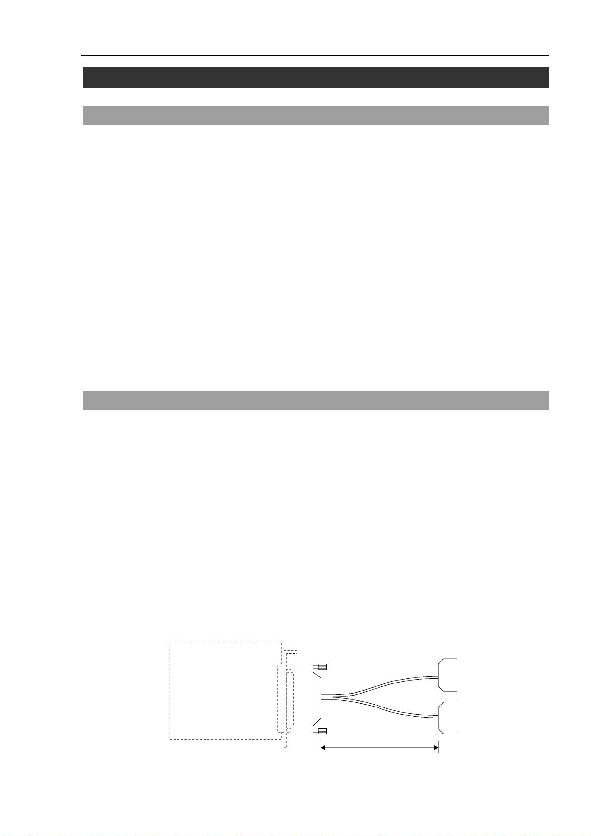
PG board
100 Pin
50 Pin
× 2
57FE-30500-20N (D8)
(DDK)
57FE-30500-20N (D8)
(DDK)
1 m
1.1 Introduction
The PG Motion System option enables you to create robots that use third party drives and
motors. PG robots can coexist with and behave similar to standard robots in the EPSON
RC+ system. Use PG robots to control auxiliary equipment such as XY tables, slides,
rotary axes, etc.
Features include:
One or more PG robots can be used along with standard robots on the same system. (Max.
16 robots in total)
PG robots can be a Cartesian or Joint type.
Both stepper motors and servo motors are supported.
Cartesian type PG robots with 2 or more axes can use Vision Guide.
PG robots are fully integrated into the EPSON RC+ environment and basically operate the
same as standard robots.
Safety features include Emergency Stop, Safeguard, over travel limits, and drive alarm.
1. Getting Started
Before using the PG Motion System option, read through this entire manual.
1.2 System Overview
The PG Motion System is a Robot Controller RC700 / RC90 option that includes a software
component of EPSON RC+ and one or more Pulse Generator boards. The customer
supplies the drives and motors using third party equipment.
The PG Motion System supports up to 4 PG boards for RC700 and 2 PG boards for RC90.
Each board has four channels, which allows a total of sixteen joints for RC700 and eight
joints for RC90. A PG robot can have from 1 to 4 joints for Cartesian coordinate robot, 1
to 7 joints for the Joint type robot.
Included in this package:
Pulse Generator board (hereinafter referred to as PG board)
PG board label (attached only if the PG board is purchased separately)
PG board connector
(Plug:DX40-100P, Cover:DX-100-CV-1 Hirose Electric Co.,Ltd.)
A PG board cable is available as an optional part. This cable is configured as shown
below:
RC700 / RC90 option PG motion system Rev.5 1
Page 12

1. Getting Started
1.3 How to Setup and Use the System
The following sections describe the basic steps on how to setup and use the PG Motion
System.
1.3.1 Hardware Setup Overview
Refer to Chapter 2, Hardware for the following instructions:
(1) Read the entire Hardware chapter and design the PG hardware for your system.
Two examples are provided.
(2) Configure and install one or more PG boards in the Controller.
(3) Wire cables for PG boards and drives.
1.3.2 Software Setup Overview
Refer to Chapter 3, Software for the following instructions:
(1) Create one or more PG robots in the EPSON RC+ system configuration.
(2) Test each PG robot and verify that all safety features are operating properly.
(3) Write SPEL+ software to control PG robots from your EPSON RC+ applications.
2 RC700 / RC90 option PG motion system Rev.5
Page 13
2. Hardware
This chapter describes the PG board hardware including the functions, switch settings, and
internal circuits of the PG board.
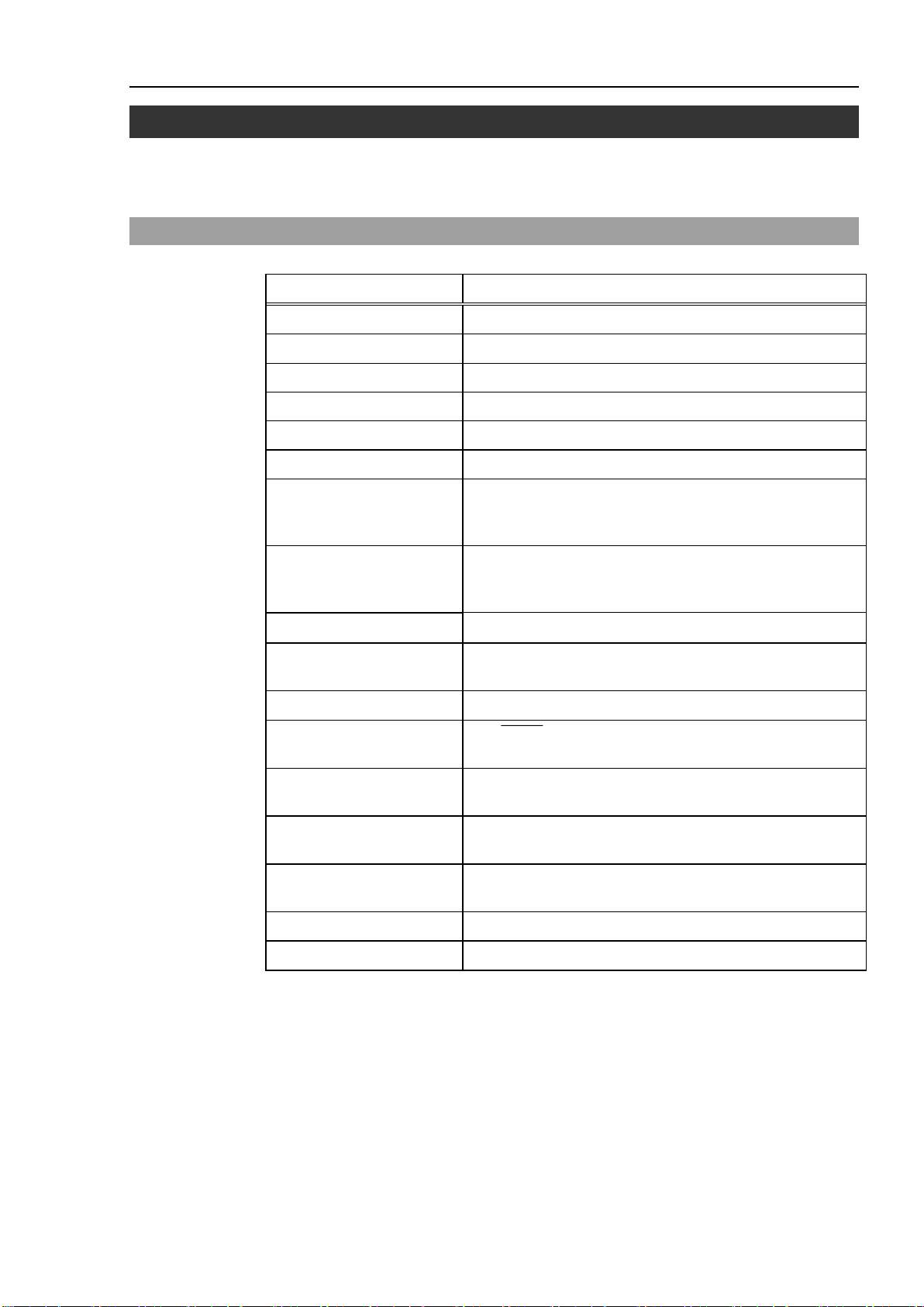
2.1 PG Board Specifications
Item Description
Board Name H756
Compatible Controller RC700 / RC90
Expansion Capability RC700: 4 boards maximum / RC90: 2 boards maximum
Control Axes 4 axes per board
Target Motor Either servo motors or stepper motors can be used.
Output Pulse Rate 0.1 pps to 6.5 Mpps
Speed Setting
2. Hardware
100 steps in the program with the flexible maximum speed
setting. The calibration speed can be programmed
separately from the normal operation speeds.
Acceleration Settings
Arm Travel Range [pulse]
Pulse Output Type
Rotating Direction Programmable in the software.
Positioning Method
Calibration
Stop Function
S-curved
Acceleration/Deceleration
Continuous Rotation Selectable in software
Relative Quantity Travel Selectable in software
The program provides 100 steps each for Acceleration and
Deceleration. (The maximum acceleration or maximum
deceleration setting can be changed.)
− 2,147,483,647 to 2,147,483,647 (32 bits)
Selectable in software: Pulse / Direction Output Method or
CW / CCW Pulse Output Method
The DEND (detection-end) signal generated from the servo
drive (when a servo drive is used).
Selectable from the seven (7) calibration types in the
software.
The pulse generation to be stopped at the input of either the
limit or alarm signal.
Selectable in software
RC700 / RC90 option PG motion system Rev.5 3
Page 14
2. Hardware
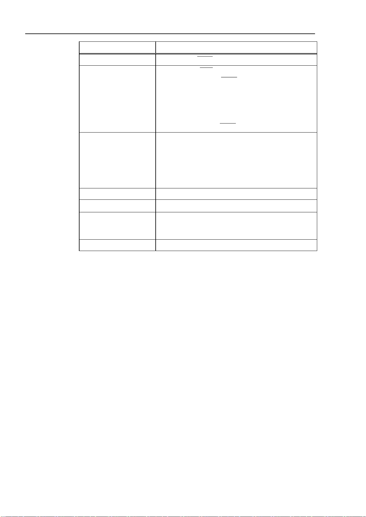
Item Description
Output Signal Counter reset (DRST)signal
Input Signal - Origin signal (ORG). Normally open.
- Near-to-origin signal (NORG). Normally open.
- CW limit signal (CWLM). Normally closed.
- CCW limit signal (CCWLM). Normally closed.
- Alarm signal (ALM)
- Encoder Phase -Z signal (ZORG)
- Detection-end signal (DEND)
Safety Features The following safety features of Robot Controller RC700 /
RC90 are supported:
- Emergency Stop Input
- Safeguard Input
- Enable SW Input
- Low/High Power Mode
Board Address Set by DIP switches on the board.
I/F Connector on the Board DX10A-100S (Hirose Electric Co.,Ltd.)
Power Supply
PG Robot Limitations Refer to the section 3.4 Using PG robots in EPSON RC+
5 V ±5 % 1.0 A (max.)
24 V ±2 V 200 mA (max.)
(from the external power source)
4 RC700 / RC90 option PG motion system Rev.5
Page 15
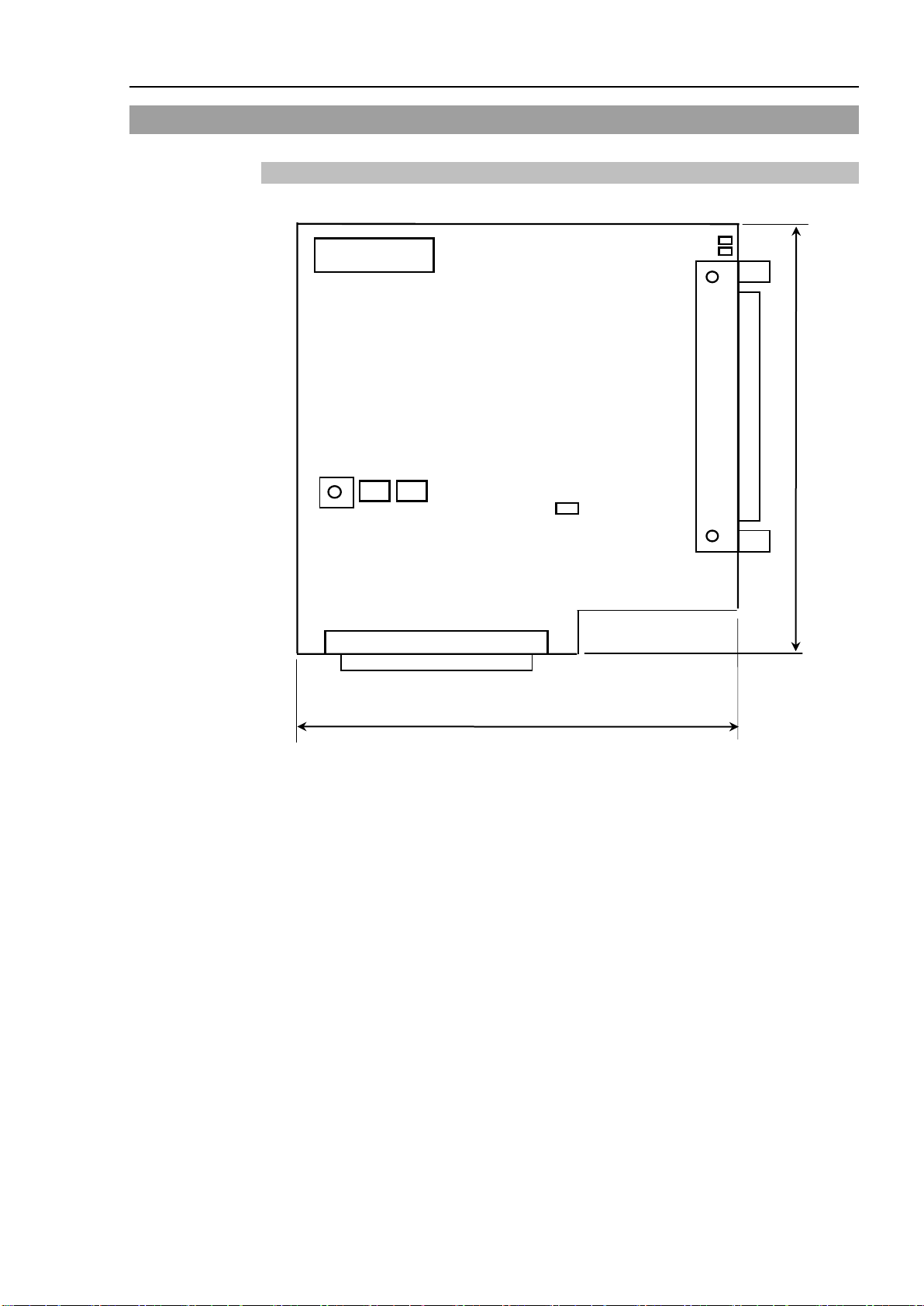
2.2 Part Names and Functions
JP1
CN2
134
130
CN1
CN3
X
Y
S3
S2
S1
2.2.1 Component Names & Locations
2. Hardware
Rotary switch : S1
DIP Switch : S2, S3
LED : X, Y
Jumpers : JP1
Connectors : CN1, CN2, CN3
RC700 / RC90 option PG motion system Rev.5 5
Page 16
2. Hardware
1 2 3 4 1 2 3 4
ON
ON : 0
OFF : 1
DIP switch
S2
DIP switch S3
ON
1 2 3 4 1 2 3 4
ON
ON : 0
OFF : 1
DIP switch S2
DIP switch S3
ON
1 2 3 4 1 2 3 4
ON
ON : 0
DIP switch S2
DIP switch S3
ON
1 2 3 4 1 2 3 4
ON
ON : 0
DIP switch S2
DIP switch S3
ON
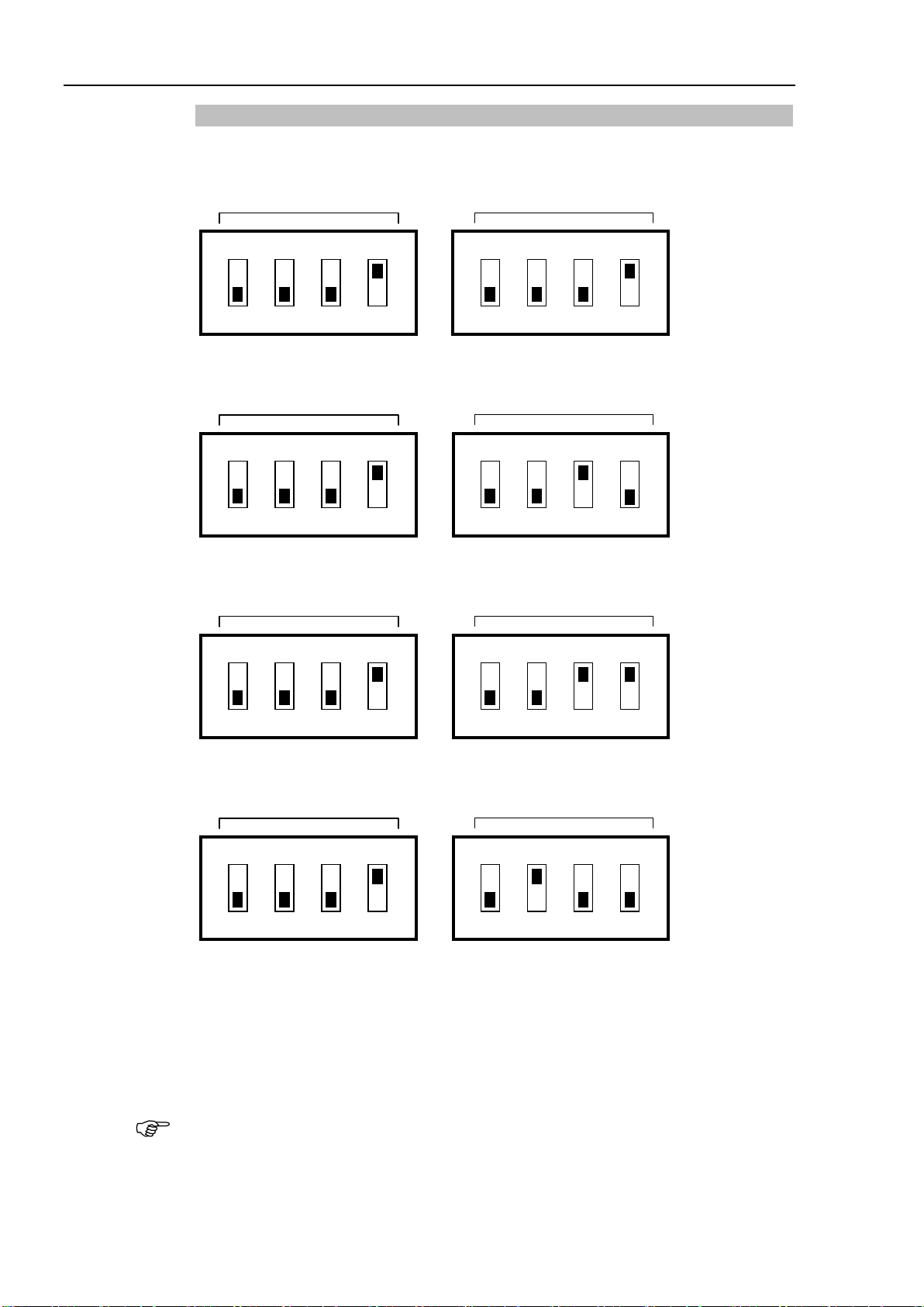
2.2.2 DIP Switch Settings
The board number is set by DIP switch (S2, S3) on the PG board.
The first PG board must be set as shown below:
The second PG board must be set as shown below:
The third PG board must be set as shown below:
OFF : 1
The fourth PG board must be set as shown below:
OFF : 1
If you purchased the PG board alone, apply the provided board number seal to the board
panel before installing to the controller and be sure to keep a written record of the board
number.
If the board has been already installed before shipment, the board number is properly
configured and there is no need of your further configuration.
NOTE
If you use the PG board for the conveyor tracking, use another address for the PG board of
the PG motion system. For example, if the PG board 1 is used for the conveyor tracking,
then use the PG board 2 for the PG motion system.
6 RC700 / RC90 option PG motion system Rev.5
Page 17

2.2.3 Jumper Settings
Do not change the jumper settings. At shipment, it is set as below:
2. Hardware
JP1 : with jumpers
2.2.4 Rotary switch Settings
Do not change the Rotary switch S1 settings. At shipment, it is set as below:
S1 : Position of 1
2.2.5 LEDs
The LEDs on the board are used to monitor the following signals:
X, Y : Inside status of each axis. Turns ON when ready to receive a command.
2.2.6 Connectors
CN1 : Connection for the external devices
(Refer to the section 2.3 Internal Circuitry for further details.)
CN2 : Unused
CN3 : Connector for internal connection
2.2.7 Installation in the Controller
Turn OFF the Controller.
Remove the open slot panel at the front of the Controller. Install the PG board and secure
it with screws. For details, refer to the instruction sheet attached to the board.
Once the board is installed, refer to the section 3.1 Creating PG Robots in EPSON RC+ for
software installation and settings.
RC700 / RC90 option PG motion system Rev.5 7
Page 18

2. Hardware
+COMMON for CWP
2.3 Internal Circuitry
2.3.1 Signal Functions
The table below describes the function of each PG board signal.
Direction Signal Name Function Description
Output +COM
+DRSTCOM
CWP
CWP
CCWP
CCWP
DRST Drive reset signal Outputs a signal to reset the drive's deviation counter.
SVON Servo ON signal Outputs the servo ON signal when connecting the PG board to the
Outputs the +5V power source for the CWP and CCWP signals.
and CCWP
+COMMON for DRST Outputs +5V for DRST signal.
Outputs CW pulses
Outputs CCW pulses
Generates the pulse train for the CW direction when the Pulse
Output parameter is set to CW/CCW.
Generates the pulse train when the Pulse Output parameter is set to
Pulse / Direction.
Generates the pulse train for the CCW direction when the Pulse
Output parameter is set to CW/CCW.
Generates the direction signal when the Pulse Output parameter is
set to Pulse / Direction (clockwise when the CCWP is low).
If the pulse output is put into a rapid stop, the DRST signal = Low is
output for 10 ms.
Must be disconnected when a stepper motor is used.
servo drive. Must be left disconnected when a stepper motor is
used.
The signal is OFF when controller is launched.
It turns OFF automatically when any one of the joints within a
manipulator indicates either a servo error or limit switch related
errors.
8 RC700 / RC90 option PG motion system Rev.5
Page 19

2. Hardware
clockwise (CW) pulses are generated.
Connect to either a photo or magnetic normally open sensor to detect the
Direction
Input CWLM CW (clockwise) Limit
Signal
Name
CCWLM CCW (counter-
NORG Near-to-Origin signal
ORG Origin signal If the motor encoder Z-Phase signal will not be used, connect either a
Function Description
signal
clockwise) Limit signal
Connect to normally closed CW Limit switch.
This signal is accepted only when
When this signal is detected, the pulse generation will be stopped either
gradually or immediately according to the software setting.
Connect to normally closed CCW Limit switch.
This signal is accepted only when counter-clockwise (CCW) pulses are
generated. When this signal is detected, the pulse generation will be
stopped either gradually or immediately according to the software
setting.
proximity of the target origin. Ensure that the proximity sensor is
always used with an origin sensor (either ORG or Z-Phase).
If a mechanical switch is used, you may need to connect a capacitor in
parallel with the switch (0.1μf 50V recommended).
photo or magnetic normally open sensor to detect the target origin.
Leave the ZORG terminal unconnected. The accuracy of calibration or
positioning can be increased and the calibration time can be shortened
by using the origin sensor with a proximity sensor (NORG).
If a mechanical switch is used, you may need to connect a capacitor in
parallel with the switch (0.1μf 50V recommended).
NOTE
+ZORG
-ZORG
DEND Detection (calibration)
ALM Alarm signal Connect the alarm signal from the drive. Generation of pulses will be
Encoder Phase -Z signal Use this terminal if the motor encoder’s Z-Phase is used as an origin
sensor in which case the ORG terminal must be left disconnected.
Connect to the signal from the drive that indicates that positioning is
end signal
complete. Must be left disconnected if a stepper motor is used.
stopped gradually or immediately when this signal is detected. The
alarm logic and the stop mode are defined in the software.
For DEND input, when a servo motor is used, the position complete signal from the drive must be
connected. After a MOVE command is executed, SPEL waits until the DEND input is activated.
When the DEND input is not activated even after waiting for a time specified by a FINE command,
a message "Error 4004: Event waiting error with the Motion Control Module." appears. In case
of this error, it is necessary to exit controller, stop the SPEL Runtime Drivers, then restart controller.
When it is expected that your servo drive does not have an output equivalent to the positioning
completion signal, or that the DEND input is not activated, the DEND input must be connected to
GND. In this case, SPEL does not check that the servo drive's positioning is completed.
Therefore, after the operation command is executed, use the time delay necessary for positioning
to be complete in your application.
RC700 / RC90 option PG motion system Rev.5 9
Page 20
2. Hardware
EXTV
ORG, NORG, DEND, ALM
Board
Drive
+24V
External power supply
ON : 2.5mA or over
OFF : 0.8mA or under
6.8kΩ
EXTV
CWLM / CCWLM
6.8kΩ
Board
Sensor
+24V
External power supply
ON : 2.5mA or over
OFF : 0.8mA or under
The CWLIM and CCWLIM limit switches must be
normally closed. The ORG and NORG switches must
be normally open.
+ZORG
-ZORG
220 Ω
26C31
equivalent
Connect to Line driver RS422 Conforming
+5V
+5V
26C32
equivalent
Board
Drive
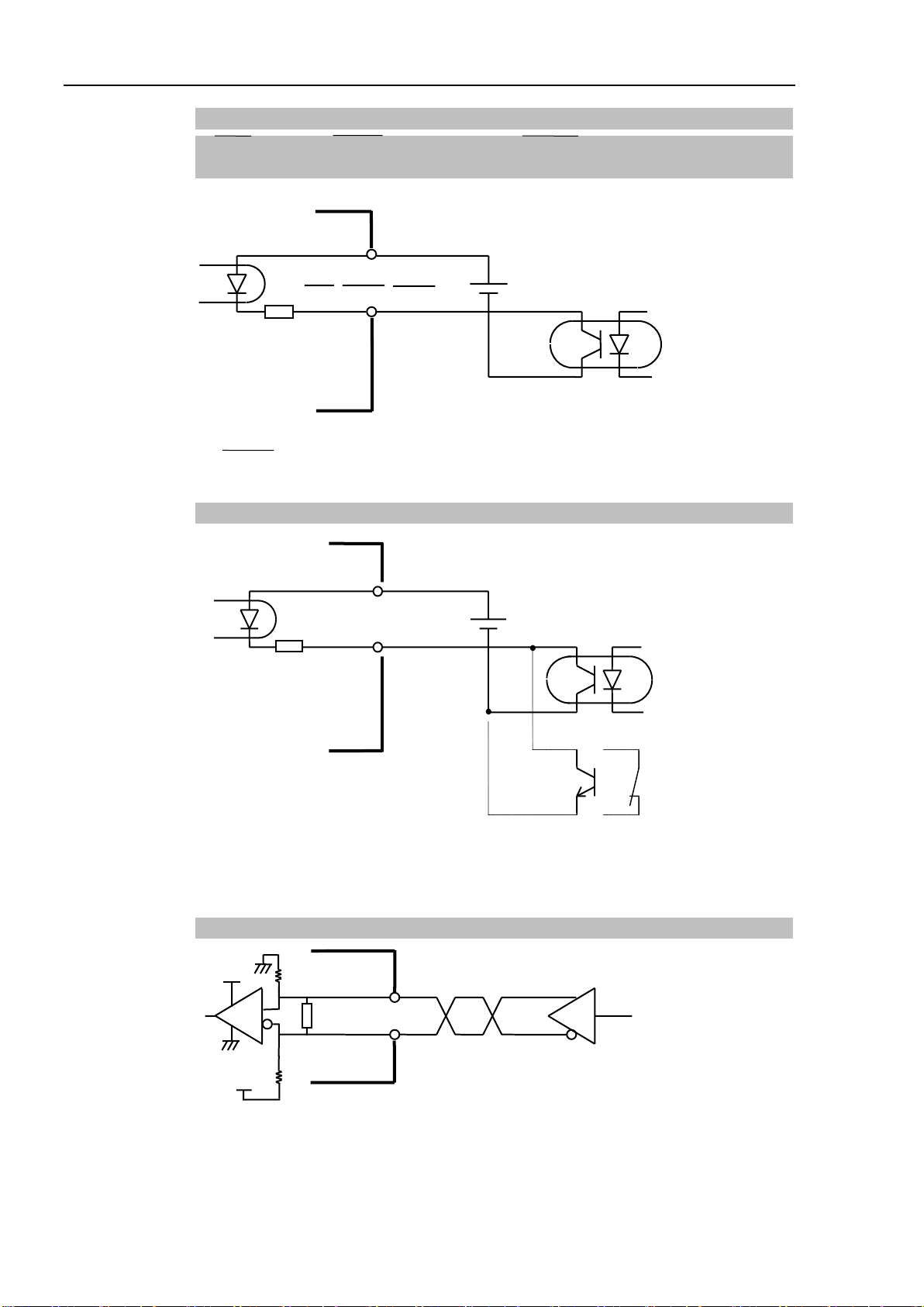
2.3.2 Input Circuit
ORG(Origin), NORG(Near-to-origin), DEND(Detection-end),
ALM(Alarm)
The DEND terminal must be left disconnected if a stepper motor is used.
The input logic of the Alarm signal can be changed in the software.
CWLM(CW Limit), CCWLM(CCW Limit)
ZORG (Encoder Phase -Z) Signal
This terminal must be connected when an Encoder Z Phase signal is used as the origin signal.
10 RC700 / RC90 option PG motion system Rev.5
Page 21

2. Hardware
CWP / CCW P
Line Driver
26C31
equivalent
CWP / CCW P
GND
Max 20mA
+5V
Board
Drive
EXTVGND
EXTV
DRST
+ DRST COM
1.65kΩ
Output Current
Maximum
50 mA
(Vce=under 2 V)
External power
supply
5 V
Board
Drive
150Ω or over
Output Current
Maximum
50 mA
(Vce=under 2 V)
EXTVGND
EXTV
DRST
External power
supply
24 V
+DRSTCOM
1.65kΩ
Board
Drive
2.3.3 Output Circuit
CWP (CW Pulse Output)/ CCWP (CCW Output) Signals
DRST (Drive Reset)
The DRST terminal does not need to be connected when a stepper motor is used.
When the servo driver counter reset input is +5V interface, refer to the connection example
below.
If the current-limiting resistor of the driver is less than 150Ω, provide an external resistor to
ensure 150Ω or more.
When the servo driver counter reset input is +24V interface, refer to the connection example
below.
RC700 / RC90 option PG motion system Rev.5 11
Page 22

2. Hardware
Output Current
Board
Drive
SVON(Servo ON)
2.4 Wiring
Follow guidelines listed below when connecting a PG board to a drive:
EXTV
SVON
Maximum
70 mA
(Vce=under 2 V)
EXTVGND
R
External power
supply
24 V
2.4.1 Minimizing Noise Interference
Minimize noise interference by using the wiring recommendations as described in the
drive manual.
Use a noise filter on the primary power supply for EXTV/EXTVGND and separate
between the primary and secondary wiring by at least 200mm.
For EXTV/EXTVGND and the instruction signals for using twisted pair (as indicated
in the circuit diagram in the previous “Input and Output Circuits”), be sure to use
twisted pair cables.
Use shielded twisted pair cable for connecting the PG board to the drive.
Follow the drive manual and the manufacturer’s instructions for shielding.
Keep the wiring between the PG board and drive as short as possible (within 1.5 m)
and position them to be separated from possible noise sources as much as possible.
For the load to be used in the controller’s (Control Unit’s) I/O, whether a relay or
solenoid, make sure to use one with surge suppressor. Install a diode (or such) on
the Load L side where there is no surge suppressor.
For such peripheral equipment as a conveyor, switching the rotating direction (start,
forward, reverse) of an AC motor (an induction motor, a 3-phase induction motor,
etc.) requires an appropriate spark suppressor between lines. The closer the
suppressor is to the motor, the more effective the noise suppression.
12 RC700 / RC90 option PG motion system Rev.5
Page 23

2. Hardware
2.4.2 Connectors
The table below lists the connectors on the PG board and the compatible connectors for
wiring:
Receptacle on the Board
Wiring Plug
Connectors
Connector for Wiring to the Cover DX30M-100-CV1
If you are using the optional cable, refer to section 2.4.4 PG Terminal Block Pin Outs later
in this chapter.
DX10A-100S
(manufacturer: Hirose Electric Co., Ltd.)
Individually
pressed-in type
Pressed-in-as-a-whole type
DX30-100P (for AWG#30)
DX30A-100P (for AWG#28)
DX31-100P (for AWG#30)
DX31A-100P (for AWG#28)
Soldered type DX40-100P
RC700 / RC90 option PG motion system Rev.5 13
Page 24

2. Hardware
ply GND for Input
put
+DRST
COM1
+DRST
COM3
2.4.3 PG Board Connector Pin Outs
The pin outs for the PG board connector (DX10A-100S) are shown in the following table.
For details of each signal, refer to section 2.3.1 Signal Functions. If you are using the
optional cable, refer to section 2.4.4 PG Terminal Block Pin Outs later in this chapter.
Pin Dir Signal Description Pin Dir Signal Description
1 In CWLM1 CW limit signal for Axis #1 (*2) 51 In CWLM3 CW limit signal for Axis #3 (*2)
2 In CCWLM1 CCW limit signal for Axis #1 (*2) 52 In CCWLM3 CCW limit signal for Axis #3 (*2)
3 In NORG1 Near-to-origin signal for Axis #1 53 In NORG3 Near-to-origin signal for Axis #3
4 In ORG1 Origin signal for Axis #1 (*1) 54 In ORG3 Origin signal for Axis #3 (*1)
5 In CWLM2 CW limit signal for Axis #2 (*2) 55 In CWLM4 CW limit signal for Axis #4 (*2)
6 In CCWLM2 CCW limit signal for Axis #2 (*2) 56 In CCWLM4 CCW limit signal for Axis #4 (*2)
7 In NORG2 Near-to-origin signal for Axis #2 57 In NORG4 Near-to-origin signal for Axis #4
8 In ORG2 Origin signal for Axis #2 (*1) 58 In ORG4 Origin signal for Axis #4 (*1)
9 − − Not used 59 − − Not used
10 In ALM1 Alarm input signal for Axis #1 60 Out SVON1 Servo ON output signal for Axis #1
11 In ALM2 Alarm input signal for Axis #2 61 Out SVON2 Servo ON output signal for Axis #2
12 In ALM3 Alarm input signal for Axis #3 62 Out SVON3 Servo ON output signal for Axis #3
13 In ALM4 Alarm input signal for Axis #4 63 Out SVON4 Servo ON output signal for Axis #4
14 In EXTV External power supply for Input
circuit
15 In EXTV
16 Out +COM CWP1, CCWP1 +COMMON 66 Out +COM CWP3, CCWP3 +COMMON
17 Out CWP1 CW pulse output signal for Axis #1 67 Out CWP3 CW pulse output signal for Axis #3
18 Out CWP1 Inverted CW pulse output for Axis #1 68 Out CWP3 Inverted CW pulse output for Axis #3
19 Out CCWP1 CCW pulse output for Axis #1 69 Out CCWP3 CCW pulse output for Axis #3
20 Out CCWP1 Inverted CCW pulse output for Axis #1 70 Out CCWP3
21 Out
22 Out DRST1 Drive Reset signal for Axis #1 72 Out DRST3 Drive Reset signal for Axis #3
External power supply for Input
circuit
DRST1 +COMMON 71 Out
64 In EXTVGND External power sup
circuit
65 In EXTVGND
External power supply GND for In
circuit
Inverted CCW pulse output for Axis
#3
DRST3 +COMMON
23 In DEND1 Detection End signal for Axis #1 73 In DEND3 Detection End signal for Axis #3
24 − − Not used 74 − − Not used
25 − − Not used 75 − − Not used
14 RC700 / RC90 option PG motion system Rev.5
Page 25

2. Hardware
-
-
+DRST
COM2
+DRST
COM4
-
-
Pin Dir Signal Description Pin Dir Signal Description
26 − − Not used 76 − − Not used
27 − − Not used 77 − − Not used
28 − − Not used 78 − − Not used
29 In +ZORG1 Encoder Phase +Z signal for Axis #1 79 In +ZORG3 Encoder Phase +Z signal for Axis #3
30 In
31 − − Not used 81 − − Not used
32 Out +COM CWP2, CCWP2 +COMMON 82 Out +COM CWP4, CCWP4 +COMMON
33 Out CWP2 CW pulse output for Axis #2 83 Out CWP4 CW pulse output for Axis #4
34 Out CWP2 Inverted CW pulse output for Axis #2 84 Out CWP4 Inverted CW pulse output for Axis #4
35 Out CCWP2 CCW pulse output for Axis #2 85 Out CCWP4 CCW pulse output for Axis #4
36 Out CCWP2 Inverted CCW pulse output for Axis #2 86 Out CCWP4 Inverted CCW pulse output for Axis #4
37 Out
38 Out DRST2 Drive Reset signal for Axis #2 88 Out DRST4 Drive Reset signal for Axis #4
39 In DEND2 Detection End signal for Axis #2 89 In DEND4 Detection End signal for Axis #4
40 − − Not used 90 − − Not used
41 − − Not used 91 − −
42 − − Not used 92 − −
43 − − Not used 93 − −
44 − − Not used 94 − −
ZORG1
Encoder Phase -Z signal for Axis #1 80 In
DRST2 +COMMON 87 Out
ZORG3
Encoder Phase -Z signal for Axis #3
DRST4 +COMMON
Not used
Not used
Not used
Not used
45 In +ZORG2 Encoder Phase +Z signal for Axis #2 95 In +ZORG4 Encoder Phase +Z signal for Axis #4
46 In
47 − − Not used 97 − −
48 − − Not used 98 − −
49 − − Not used 99 − −
50 − GND Ground 100 − GND Ground
ZORG2 Encoder Phase -Z signal for Axis #2
96 In
ZORG4 Encoder Phase -Z signal for Axis #4
Not used
Not used
Not used
(*1) Leave this terminal disconnected if you use Encoder Z Phase signal as the origin signal when a servo
motor is used.
(*2) When the status of the limit signal is OFF (the photo coupler in the input circuit is OFF), the axis is
deemed to be out of the Permissible Working Range and pulse generation will be stopped. Therefore,
you must connect to an external power source so that the limit signal(s) will remain ON when your system
configuration does not use limit signals.
RC700 / RC90 option PG motion system Rev.5 15
Page 26

2. Hardware
2.4.4 PG Terminal Block Pin Outs
When the optional cable is used, 2 terminal blocks are provided. Pin outs for these terminal
blocks are shown in the following two tables. The pin numbers in parentheses are the pins
on the PG board connector. For details of each signal, refer to the section 2.3.1 Signal
Functions.
Pin Signal Description Pin Signal Description
1 (16) +COM CWP1,CCWP1 +COMMON 26 (32) +COM CWP2, CCWP2 +COMMON
2 (17) CWP1 CW pulse output signal for Axis #1 27 (33) CWP2 CW pulse output for Axis #2
3 (18) CWP1 Inverted CW pulse output for Axis #1 28 (34)
4 (19) CCWP1 CCW pulse output for Axis #1 29 (35) CCWP2 CCW pulse output for Axis #2
5 (20)
6 (21)
7 (22) DRST1 Drive Reset signal for Axis #1 32 (38) DRST2 Drive Reset signal for Axis #2
8 (23) DEND1 Detection End signal for Axis #1 33 (39) DEND2 Detection End signal for Axis #2
9 (24) - Not used 34 (40) - Not used
10 (25) - Not used 35 (41) - Not used
11 (26) - Not used 36 (42) - Not used
12 (27) - Not used 37 (43) - Not used
13 (28) - Not used 38 (44) - Not used
14 (29) +ZORG1 Encoder Phase +Z signal for Axis #1 39 (45) +ZORG2 Encoder Phase +Z signal for Axis #2
15 (30) -ZORG1 Encoder Phase -Z signal for Axis #1 40 (46) -ZORG2 Encoder Phase -Z signal for Axis #2
16 (31) - Not used 41 (47) - Not used
17 (48) - Not used 42 (49) - Not used
18 (9) - Not used 43 (50) GND Ground
19 (60) SVON1 Servo ON output signal for Axis #1 44 (61) SVON2 Servo ON output signal for Axis #2
20 (10) ALM1 Alarm input signal for Axis #1 45 (11) ALM2 Alarm input signal for Axis #2
21 (1) CWLM1 CW limit signal for Axis #1 46 (5) CWLM2 CW limit signal for Axis #2
22 (2) CCWLM1 CCW limit signal for Axis #1 47 (6) CCWLM2 CCW limit signal for Axis #2
23 (3) NORG1 Near-to-origin signal for Axis #1 48 (7) NORG2 Near-to-origin signal for Axis #2
24 (4) ORG1 Origin signal for Axis #1 49 (8) ORG2 Origin signal for Axis #2
25 (14) EXTV
CCWP1
+ DRST
COM1
PG Terminal Block 1
Inverted CCW pulse output for Axis #1 30 (36)
DRST1 +COMMON 31 (37)
External power supply for Input
circuit
50 (64) EXTVGND
CWP2
CCWP2
+ DRST
COM2
Inverted CW pulse output for Axis #2
Inverted CCW pulse output for Axis #2
DRST2 +COMMON
External power supply GND for Input
circuit
16 RC700 / RC90 option PG motion system Rev.5
Page 27

2. Hardware
External power supply GND for
Pin Signal Description Pin Signal Description
1 (66) +COM CWP3, CCWP3 +COMMON 26 (82) +COM CWP4, CCWP4 +COMMON
2 (67) CWP3 CW pulse output signal for Axis #3 27 (83) CWP4 CW pulse output for Axis #4
PG Terminal Block 2
3 (68)
CWP3
Inverted CW pulse output for Axis #3 28 (84)
CWP4
Inverted CW pulse output for Axis #4
4 (69) CCWP3 CCW pulse output for Axis #3 29 (85) CCWP4 CCW pulse output for Axis #4
5 (70)
6 (71)
CCWP3
+ DRST
COM3
Inverted CCW pulse output for Axis #3 30 (86)
DRST3 +COMMON 31 (87)
CCWP4
+ DRST
COM4
Inverted CCW pulse output for Axis #4
DRST4 +COMMON
7 (72) DRST3 Drive Reset signal for Axis #3 32 (88) DRST4 Drive Reset signal for Axis #4
8 (73) DEND3 Detection End signal for Axis #3 33 (89) DEND4 Detection End signal for Axis #4
9 (74) - Not used 34 (90) - Not used
10 (75) - Not used 35 (91) - Not used
11 (76) - Not used 36 (92) - Not used
12 (77) - Not used 37 (93) - Not used
13 (78) - Not used 38 (94) - Not used
14 (79) +ZORG3 Encoder Phase +Z signal for Axis #3 39 (95) +ZORG4 Encoder Phase +Z signal for Axis #4
15 (80) -ZORG3 Encoder Phase -Z signal for Axis #3 40 (96) -ZORG4
Encoder Phase -Z signal for Axis #4
16 (81) - Not used 41 (97) - Not used
17 (98) - Not used 42 (99) - Not used
18 (59) - Not used 43 (100) GND Ground
19 (62)
SVON3
Servo ON output signal for Axis #3 44 (63)
SVON4
Servo ON output signal for Axis #4
20 (12) ALM3 Alarm input signal for Axis #3 45 (13) ALM4 Alarm input signal for Axis #4
21 (51) CWLM3 CW limit signal for Axis #3 46 (55) CWLM4 CW limit signal for Axis #4
22 (52) CCWLM3 CCW limit signal for Axis #3 47 (56) CCWLM4 CCW limit signal for Axis #4
23 (53) NORG3 Near-to-origin signal for Axis #3 48 (57) NORG4 Near-to-origin signal for Axis #4
24 (54) ORG3 Origin signal for Axis #3 49 (58) ORG4 Origin signal for Axis #4
25 (15) EXTV External power supply for Input circuit 50 (65) EXTVGND
RC700 / RC90 option PG motion system Rev.5 17
Input circuit
Page 28

2. Hardware
Command pulse input
Command pulse input
Deviation counter clear
150Ω or more *2
(For 5V spec *1)
Servo ON
(For 24V spec)
Detection End output
Alarm output
Z phase output
Signal ground
Motor driver
External power source
*1 : For the 24V spec input circuit
on the driver side, refer to
2.3.3. Output Circuit - DRST.
*2 : If the current limiting resistance
of input circuit on the driver
side is 150Ω or less, ensure
more than 150Ω with the
external resistor.
+DRST
COM
2.4.5 Typical Applications
Example of connection with the servo motor driver
18 RC700 / RC90 option PG motion system Rev.5
Page 29

Stop generating pulse gradually (by decelerating) or rapidly.
stop function is supported only by the software.
Emergency stop must also be supported in hardware also.
Make sure to install an additional circuit for the purpose of
at the input of Emergency Stop
.
2.5 Safety Features
The PG Motion System supports the same safety features as for standard robots. The
following table describes how each system safety feature is supported for PG robots.
Safety Features Supported Function on the PG Board
Emergency Stop Input
Safety Door Input The function of this input is same as for a standard robot.
High/Low Power Mode The function of this mode is same as for a standard robot.
2. Hardware
You may select either of the two patterns in the software. This
emergency
stopping the motor physically in case of emergency. Refer to
the sample circuit diagram on the next page in which the motor
drive power is turned OFF
signal to the Controller. For more details, refer to the Robot
Controller manual.
The acceleration/deceleration is set as follows for the Low
Power and High Power state respectively:
Low Power : Acceleration and deceleration will be limited
The acceleration and deceleration value of
default are fixed as follows:
Acceleration : 10%
Deceleration : 5%
High Power : The maximum speed, acceleration and
deceleration will be operable at the set-up
maximum value in the software.
Enable Switch Input The function of this input is same as for a standard robot.
Mode Switch Input The function of this input is same as for a standard robot.
For more Safety Features, refer to the Robot Controller manual or the Safety Chapter in the
EPSON RC+ User’s Guide.
RC700 / RC90 option PG motion system Rev.5 19
Page 30

2. Hardware
External +24 V
Fuse
1A or less
External +24 V GND
External +24 V
AC Power
Source
Noise
Filter
Circuit
Breaker
External safety relay
(Simple Chart)
RC700
/ RC90
CAUTION
■
Always take anti-surge measures for coils (electromagnetic contactors, relays,
etc.) or contacts. If anti
flow. The reverse current may cause damage to peripheral equipment.
2.5.1 Typical Application of Emergency Stop Circuit
Connecting external safety relay
-surge measures are not taken, a reverse current may
20 RC700 / RC90 option PG motion system Rev.5
Page 31

3. Software
This chapter describes the software setup to use the PG Motion System.
3.1 Creating PG Robots in EPSON RC+
The PG Motion System can control up to four axes per PG board, so there can be from one
to four PG robots per board, depending on the number of axes per robot.
3. Software
NOTE
If you are also using PG boards for Conveyor Tracking in the same system, those boards are
only used for conveyor tracking encoders. PG boards used for the PG Motion System are
used separately, but are enumerated in the system along with the PG boards used for
conveyor tracking. If you add a PG board to the system for use with the motion system
and there is already one or more boards used for conveyor tracking, then the PG board #
will be the next board after the conveyor tracking PG boards. For example, if you add 1
PG board for conveyor tracking, and then add a board for PG motion, that board will be #2.
To create a PG robot in EPSON RC+, follow these steps:
Turn on the Controller and launch EPSON RC+.
(1)
(2) Select [Setup] - [System Configuration]-[Robots].
(3)
Click the
button. The Add New Robot dialog will be displayed. Enter the
Add
name of the robot and serial number. Select PG motion system.
RC700 / RC90 option PG motion system Rev.5 21
Page 32

3. Software
Select PG board A, Robot Type, and the number of joints used on the robot.
(4)
For the Cartesian coordinate robot, select “Cartesian”.
For the Joint type robot, select “Joint”.
In case of the Joint type robot with more than 5 joints, select also “PG board B”.
(5) Click the OK and reboot the controller.
(6) After the controller is rebooted, a PG robot is added to EPSON RC+.
22 RC700 / RC90 option PG motion system Rev.5
Page 33

3.2 PG Robot Configuration
■
Set
If
unexpected movement of the
damage to the
Once a PG robot has been added to the system, you must configure it for the PG Robot
Configuration.
3.2.1 PG Robot Parameters Overview
To configure parameters for a PG robot:
Start EPSON RC+.
(1)
(2) Select [Setup]-[System Configuration]-[Robot].
(3) Select a PG parameter of the PG robot you want to edit the setting.
3. Software
(4) Follow the instruction in 3.2.3 PG Parameter and follows to change the parameter
settings.
Click
PG robot parameters with extra caution.
parameters are set improperly, the robot may move unexpectedly. The
CAUTION
Apply
to save the new settings.
robot is extremely hazardous and may cause
robot and / or peripheral equipment.
RC700 / RC90 option PG motion system Rev.5 23
Page 34

3. Software
3.2.2 PG Parameters
This dialog allows you to configure the parameters for the new robot. If you already
have a data file from a previously created PG robot, click OK to accept default
parameters, then use the Load Parameters button to load the data file.
If you have a PG robot data file previously created
Load the data file by following the instruction in the section 3.2.4 Backup and Restore
Parameter Data.
If you don't have a data file, then proceed to the following sections to configure the
PG robot parameters.
If you don’t have a data file
Set the PG robot parameter in the dialog shown below.
User Model Name
Name the model of the manipulator here. You may create your own type-name using a
maximum of 32 alphanumeric characters.
The User Model Name entered here will appear as the robot type in Robot Configuration.
The User Model Name does not affect robot operation.
Model Version
This indicates the data version in a 4-digit hexadecimal number. This information does
not affect robot operation. The version number is for your own use to indicate different
versions of robots using the same User Model Name.
Home Speed
This parameter sets the speed when Home is executed, specified by percentage of
maximum speed. The value must be an integer in the range of 1 to 100.
Home Accel
This parameter sets the acceleration when HOME is executed, specified by percentage of
maximum acceleration. The value must be an integer in the range of 1 to 100.
Mcal Speed
This parameter sets the speed when MCAL is executed, specified by percentage of
maximum speed. The value must be an integer in the range of 1 to 100.
24 RC700 / RC90 option PG motion system Rev.5
Page 35

3. Software
NOTE
Mcal Accel
This parameter sets the acceleration when MCAL is executed, specified by percentage of
maximum acceleration. The value must be an integer in the range of 1 to 100.
Specify this parameter so that MCAL is completed within 120 seconds.
If the calibration of each joint is not completed within 120 seconds during MCAL execution,
then error 4083: MCAL did not complete in time will occur.
3.2.3 PG parameter Joint
RC700 / RC90 option PG motion system Rev.5 25
Page 36

3. Software
Alarm Logic
The ALM input logic is defined as follows when you select either Active High or Active
Low from the drop-down list:
Active High
Active Low
The alarm status is active when the input at the ALM input terminal is
at High Active.
The alarm status is active when the input at the ALM input terminal is
at Low Active.
Cal Direction
This setting defines the direction for the joint to move when calibrating the mechanical
origin:
Normal
Reverse
The joint moves in the normal direction during calibration of the
mechanical origin.
The joint moves in the reverse direction during calibration of the
mechanical origin.
Cal Jog Delay
The Jog Delay sets the delay (in msec) per pulse for the low speed, pulse-by-pulse
operation during signal detection.
The value must be an integer in the range of 0 to 1275 and a multiple of 5 (msec).
Cal Limit Delay
The Limit Delay sets the time duration (in msec) before reverse motion starts after either
the CCW or CW Limit is detected during calibration.
The value must be an integer in the range of 0 to 1275 and a multiple of 5 (msec).
Cal Org Detect Speed
This is the speed for detecting the sensor edge in pulses/sec.
The value must be an integer in the range of 1 to 65535.
Cal Scan Delay
The Scan Delay sets the time duration (in msec) before reverse motion starts after the stop
command is input during calibration.
The value must be an integer in the range of 0 to 1275 and a multiple of 5 (msec).
Cal Type ORG
The Calibration Type specifies the calibration method used to calibrate the mechanical
origin. There are seven calibration types 0, 1, 2, 3, 4, 5 and 10. For details of each
type, refer to 4. Calibration Types.
26 RC700 / RC90 option PG motion system Rev.5
Page 37

3. Software
the motion commands for
are
Clear MCal
The check on this box clears the existing MCAL records when either MOTOR OFF or
SFREE is executed. Execution of either MOTOR OFF or SFREE necessitates
execution of MCAL after the motor is let go of servo by either of these commands.
False
True
The MCAL records will not be cleared when either MOTOR OFF or SFREE is
executed. If it is a stepping motor that is driving the joint, this box must be left
unchecked.
The MCAL records will be cleared when either MOTOR OFF or SFREE is
executed. Execution of either MOTOR OFF or SFREE necessitates execution of
MCAL after the motor is let go of servo by either of those commands. If it is a
servo motor connected to the SVON output that is driving the joint, this box must
be checked.
Continuous Motion
Enables the continuous rotation in the any direction. This is used in the rotary table or
other controls. This is for only the Joint type robots.
Disabled Continuous operation is not enabled (Default)
Continuous operation is enabled
If the continuous operation is enabled, normal absolute position
Abled
management is not executed. In addition, only
the continuous rotation (PG_Scan, PG_SlowStop, PG_FastStop)
enabled and the manipulator will not move with other motion commands.
PG_Scan 0 : Continuous motion in CW direction.
Default Horder
When Home (a command to move to the user-defined home position) is executed, each
joint will be moved to the -defined home position in the order as specified by the Horder
command.
When the user clicks Default button in the Tool | Robot manager | Home Config, these
values will be used.
For the details, refer to 3.3.3 [Home Config].
Default MCORDR
When MCAL (calibration to the home position) is executed, each joint will be calibrated
to the mechanical home position in the order as specified by the MCORDR command.
When you click Default button in the Tool | Robot manager | Mcal Order, these values
will be used.
For the details, refer to 3.3.4 [Mcal Order].
RC700 / RC90 option PG motion system Rev.5 27
Page 38

3. Software
Initial Pulse Width
Use this parameter to control the initial pulse width to prevent power swing at the stepper
motor. The value in the range of 1 to 8388607.
Limit Stop Mode
This specifies how the robot will be stopped when a limit signal is turned OFF. Select
from the drop-down list box either Rapid Stop (stop immediately) or Decel Stop
(gradually decelerate to stop).
Margin Pulses
During the calibration without the acceleration or deceleration, when the calibration
signal is detected, the arm stops after moving for the part of margin pulses in the traveling
direction. This is used to prevent the false detection by the origin signal chattering or
hunting. The value must be an integer in the range of 1 to 65535.
Max Accel, Max Decel Max, Speed
These correspond with the SPEL+ commands SPEED 100, and ACCEL 100, 100, whose
values are percentages.
maximum speed [pulse/sec] Real value from 0.1 to 6553400.0
maximum acceleration [pulse/sec2]
Real value from 200.0 to 400000000.0
maximum deceleration [pulse/sec2]
Max Range, Min Range
This is the default working range for the robot. The value must be a signed integer in
the range of −2147483648 to 2147483647.
When the user clicks Default button in the Tool | Robot manager | Range, these values
will be used.
For the details, refer to 3.3.2 [Range].
Motor Type
Specifies the target motor type. Select either Servo or Stepper.
If Servo is selected, the following signals will become effective: Positioning Output of
the servo drive (DEND), Counter Reset Input (DRST) and Servo ON (SVON).
Origin Pulses
Specifies the pulse position after the calibration. The specified pulse value is the
position at where the arm is after the calibration with MCal. The value must be a
positive / negative integer.
Physical / Logical Pulses
Set the relation of the direction of the motor rotation and the pulse values (coordinate
values) in SPEL+. Select Same or Reverse from the drop-down list.
Same As physical encoder values increase, SPEL+ pulse values increase.
Reverse As physical encoder values increase, SPEL+ pulse values decrease.
28 RC700 / RC90 option PG motion system Rev.5
Page 39

3. Software
For this setting, the pulse signal is generated from the CWP output
For this setting, the pulse in + (CW) direction is generated from the
When the relative motion is enabled, normal absolute position management
is not executed. The point data for the motion command is considered as
degrees
from the current position.
Pulse Output
Select the pulse output type from the drop-down list to match to the motor drive’s
specification:
Pulse / Direction
CW / CCW
while the Direction signal will be generated from the CCWP output.
The direction will be + (CW) when CCWP is low, and – (CCW)
when CCWP is high.
CWP terminal while the pulse in – (CCW) direction will be generated
from the CCWP terminal.
Reduction Ratio Joint, Reduction Ratio Pulses
This defines the number of pulses that correspond with the travel distance in millimeters
or degrees.
This sets the pulse number to the reduction ratio pulse, travel distance (angle) to the
reduction ratio joint.
Input range is an integer from 1.0 ~ 1000000.0.
Relative Motion
This enables the relative rotary motion in any directions. This is used to control such as
the rotary index. This is for only the Joint type robots.
Disabled Relative motion is not enabled (Default)
Relative motion is enabled
Abled
SCurve
This sets the acceleration speed curve to Straight or S-curve Acceleration/Deceleration.
Disabled Straight Acceleration/Deceleration (Default)
Abled
Z Joint
Specify the joint designated as Z-joint (vertical operation joint) when the JUMP command
is executed in SPEL+. For Cartesian robots, the Z joint is fixed at joint #3.
the relative travel amount from the current position.
Go XY(100, 0, 0, 0) ‘ Moves 100 mm or 100
S-curve Acceleration/Deceleration
In the S-curve Acceleration/Deceleration, it creates an
acceleration/decelerat
ion curve which changes the speed smoothly.
Also, it can prevent the triangle drive in small distance motions.
RC700 / RC90 option PG motion system Rev.5 29
Page 40

3. Software
3.2.4 Backup and Restore Parameter Data
After creating a PG robot, you can save its parameter data in a file. This file can be used
as a backup, and can also be used to create PG robots on other systems.
To backup PG robot parameter data:
(1) Select System Configuration from the Setup menu.
(2) Select the Robot from the System Configuration.
(3) Select the desired PG robot from the list of Robot, and then select a PG parameter.
(4) Click the <Save>button.
(5) Browse to the desired location and enter the desired filename.
(6) Click the <Save>button.
30 RC700 / RC90 option PG motion system Rev.5
Page 41

3. Software
To restore PG robot parameter data:
(1) Select System Configuration from the Setup menu.
(2) Select the Robot from the System Configuration
(3) Select the desired PG robot from the list of Robot, and then select a PG parameter.
(4) Click the <Load>button.
(5) Browse to the desired location and select the desired filename.
(6) Click the <Open> button. The parameters are now loaded.
RC700 / RC90 option PG motion system Rev.5 31
Page 42

3. Software
3.3 [Robot Manager] Configuration
After the PG robot parameter configuration is completed, now you need to set the parameters
in the [Robot Manager].
3.3.1 Overview of [Robot Manager]
This is used to control the robot motors and power, jog robots, teach points, and view/edit
several parameters for the robot.
For the details, refer to EPSON RC+ Users Guide: 5.11.1 [Robot Manager Command]
(Tools Menu).
This section describes an instruction for the PG robot parameter setting.
How to edit the [Robot Manager]
(1) Start the EPSON RC+.
(2) Select the Robot Manager from the Tools menu.
(3) Follow the instruction in the section 3.3.2 [Range] or later to change the parameters.
(4) Click the <Apply> button and save the new settings.
32 RC700 / RC90 option PG motion system Rev.5
Page 43

3. Software
3.3.2 [Range]
Set the robot motion range. Click the <Default> button if you want to load the default
values set in the section 3.2.3 PG parameter Joint.
For each Joint (J1 through J4), specify the minimum value in the box on your left and the
maximum on the right. The value must be a signed integer in the range of -2147483647
to 2147483647.
3.3.3 [Home Config]
When HOME (a command to move to the user-defined home position) is executed, each
joint will be moved to the user-defined home position in the order as specified by the
HORDR command.
Click the <Default> button if you want to load the default values set in the section 3.2.3 PG
parameter Joint.
RC700 / RC90 option PG motion system Rev.5 33
Page 44

3. Software
NOTE
J1 through J6 represent Joint #1 through Joint #6 respectively and, they are moved to the
user-defined home position in the order as specified by Step 1 through Step 4. In the
illustrated example, the Joint #2 will be moved to the user-defined home position after Joint
#1 is calibrated and moved to the waiting position.
3.3.4 [Mcal Order]
Specify this parameter so that MCAL is completed within 120 seconds.
If the calibration of each joint is not completed within 120 seconds during MCAL execution,
then error 4083, MCAL did not complete in time, will occur.
When MCAL (calibration to the home position) is executed, each joint will be calibrated to
the mechanical home position in the order as specified by the MCORDR command. The
values to be entered here specify the default values for MCORDR.
Click the <Default> button if you want to load the default values set in the section 3.2.3 PG
parameter Joint.
J1 through J6 represent Joint #1 through Joint #6 respectively and they will be calibrated in
the order as specified by Step 1 through Step 4. In the illustrated example, the Joint #2
will be calibrated to the origin position after Joint #1 is calibrated and moved to the origin
position.
34 RC700 / RC90 option PG motion system Rev.5
Page 45

3.4 Using PG Robots in EPSON RC+
Joint #
Joint Name
1 X 2 Y 3 Z 4
U
Joint
J1
J2
J3
J4
J5
J6
J7
Position
CX(Here)
CY(Here)
CZ(Here)
CU(Here)
CV(Here)
CW(Here)
CR(Here)
coordinate
CX(Pn)
CY(Pn)
CZ(Pn)
CU(Pn)
CV(Pn)
CW(Pn)
CR(Pn)
PG robots behave similar to standard robots. You use Robot Control Panel, Jog & Teach,
Point Editor, etc. the same as you would with standard robots.
Refer to the EPSON RC+ User's Guide for details on using the GUI and program
development.
The following sections contain additional information that is specific to PG robots.
3.4.1 PG Cartesian Robots
PG Cartesian robots can be from 1 to 4 joints. The joint names are shown in the table
below.
3. Software
Current
Point
Joint #3, if used, is fixed as the Z joint. You cannot set which joint is the Z joint for a PG
Cartesian robot.
Vision Guide supports Cartesian robots with 2 or more joints.
PG Cartesian robots support Arm, Tool, and Local.
PG Joint robots do not have an XY coordinate system.
Vision Guide does not support Joint robots (since there is no XY coordinate system).
PG Joint robots do not support Arm, Tool, and Local.
The table below shows the functions used to retrieve coordinates for joint robots.
Normally, for Joint robots, use Agl and PAgl functions. However, you can also use the
CX, CY, CZ, CU functions, as shown.
Agl(1)
PAgl(Pn, 1)
3.4.2 PG Joint Robots
Agl(2)
PAgl(Pn, 2)
Agl(3)
PAgl(Pn, 3)
Agl(4)
PAgl(Pn, 4)
Agl(5)
PAgl(Pn, 5)
Agl(6)
PAgl(Pn, 6)
Agl(7)
PAgl(Pn, 7)
3.4.3 Tuning
Tuning for PG robot drives is handled by the third party motor drive. Refer to the drive
manufacturer's instructions on how to tune the drive. EPSON RC+ does not provide any
commands for tuning the drive. However, if the drive can be controlled from a DLL, it is
possible to execute DLL functions from a SPEL+ program.
RC700 / RC90 option PG motion system Rev.5 35
Page 46

3. Software
3.4.4 Motion Commands
PTP (point to point) motion commands are supported for PG robots. These include Go,
TGo (Cartesian only), and Jump.
Joint motion is not synchronized for PG robots. When a motion command using more than
one joint is executed, the joints do not complete their motion at the same time.
CP motion (linear interpolated) commands are not supported. These include Move,
TMove, Arc, and Curve.
The Jump motion command is supported for PG robots that have a Z joint.
PASS operation with CP ON is not continuous. A PASS operation cannot be continued to
the next operation as one smooth continuous motion in which an action to the first PASS
operation/command slows down to move into another action in accelerating motion.
Attempting a PASS operation via CP ON command will only operate the manipulator by
one motion at a time.
3.4.5 SLock and SFree
Connecting the servo drive to the SVON signal enables servo excitation control via the
SLock and SFree commands. However, MCal must be executed before servos can be set
to free. (This is because the manipulator is possibly out of position while at servo-free.)
In order to ensure MCal execution, set as follows in the software: Enable the [Clear MCal]
in the Configuration dialog | System the Robot.
When you execute a manipulator motion command without executing MCal command, error
message “Error 4014: MCAL has not completed.” is displayed.
The stepper motor itself is not capable of controlling excitation, and normally, the SVON
output signal cannot be used. However, by executing SFree, the manipulator can be
operated in a pseudo servo-free state when the motor is actually engaged. When you
execute SFree, make sure to execute SLock in order to restore the excitation state.
3.4.6 Dry Run
PG robots are not directly supported in Dry Run. For PG robots to be used, the PG board
hardware must exist on the system. If you enable Dry Run in EPSON RC+, the PG robots
will continue to operate from the hardware.
36 RC700 / RC90 option PG motion system Rev.5
Page 47

3. Software
3.4.7 PG Signal Status Display
Input and output status of the PG board can be displayed on the EPSON RC+ GUI.
When the PG robot is selected, open the [I/O Monitor] of the EPSON RC and select [PG
Status] tab.
The [PG Status] tab cannot be displayed in the [I/O Monitor] in the Operator mode.
DRIVE signal turns “On” while the pulse waveform is output. It does not represent the
status of the pulse waveform itself.
RC700 / RC90 option PG motion system Rev.5 37
Page 48

4. Calibration Types
Standard Number
4. Calibration Types
The table below lists the seven Calibration Types. These calibration types determine
how the mechanical origin is determined during MCal.
Cal
Number of
Type
0 1 OFF 2 C Shorter
1 1 ON 2 C Shorter
2 1 OFF 4 B Longer
3 1 ON 4 B Longer
4 2 OFF 4 or 5 A Longest
5 2 ON 4 or 5 A Longest
10 2 ON 2 C Shortest
sensors
*1: A is highest accuracy followed by B and then C.
*2: Complete the calibration of each joint within 120 seconds.
Sensor Status when
calibration is complete
of Steps
Accuracy
Calibration
*1
Time
*2
38 RC700 / RC90 option PG motion system Rev.5
Page 49

4. Calibration Types
The arrow indicates the two types of operation speed as follows:
Run at the speed as specified in the MCAL tab of the PG Robot
Configuration dialog.
Run at the speed as specified in the Origin Edge Detect Speed in
the Calibration tab of the PG Robot Configuration dialog.
The following symbols marked next to (Pause) in the illustration indicates the
duration of time to pause as follows:
or The starting position of the search for the mechanical origin.
Pause
The position for the calibration to complete. (A target origin)
The accelerating or decelerating motion in the direction of arrow
while detecting signals. (Dotted Line indicates a motion to return
to the origin from outside the Permissible Working Range.)
The motion without acceleration or deceleration in the direction of
arrow while detecting signals.
The motion in the slow speed pulse by pulse in the direction of
arrow while detecting signals.
Calibration Sequence per Calibration Type
The following conventions and symbols are used in the Calibration Sequence diagram in
the following pages:
LD Pause for delay time as specified in
the PG Robot Configuration dialog.
SD Pause for delay time as specified in
the PG Robot Configuration dialog.
JD Pause for delay time as specified in
PG Robot Configuration dialog.
RC700 / RC90 option PG motion system Rev.5 39
Limit Delay
Scan Delay
Jog Delay
on Calibration tab of
on Calibration tab of
on Calibration tab of the
Page 50

4. Calibration Types
Cal Type 0 ORG pulse width : 1 msec or over
Cal Type 1 ORG pulse width : 1 msec or over
Cal Type 2 ORG pulse width : 1 msec or over
Cal Type 3 ORG pulse width : 1 msec or over
Cal Type 4 NORG pulse width : 1 msec or over
The interval between the NORG signal edge and ORG signal edge:
5 msec or over
+ZORG/-ZORG pulse width : 10 µsec or over (when a servo motor
is used.)
Cal Type 5 NORG pulse width : 1 msec or over
The interval between the NORG signal edge and ORG signal edge:
5 msec or ove
r
+ZORG/-ZORG pulse width : 10 µsec or over (when a servo motor
is used)
Cal Type 10 NORG Signal width : 1 msec or over
The interval between the NORG signal edge and ORG signal edge
must be sufficient to enable the robot to stop by deceleration.
Whichever Calibration Type is specified, wiring must be done in such a way to prevent
chattering. Also, the following signal conditions must be satisfied:
40 RC700 / RC90 option PG motion system Rev.5
Page 51

4. Calibration Types
<1
<2>
<3>
<4>
<1> <2
When the starting position is in the range of A above. (Operation: 2 steps)
target origin
Working Range
CW (CCW)
Calibration Type 0
For Calibration Type 0, calibration is accomplished using one sensor. Place the sensor
closer to the CCW Limit position. Configure the sensor to detect the ORG signal edge
( ↑ ) in the CW direction.
CCW (CW)
Limit Position
ORG
CW LIMIT
CCW LIMIT
CW (CCW) direction CCW (CW) direction
Limit Position
C
>
When the starting position is in the range of B above. (Operation: 4 steps)
>
LD
When the starting position is in the range of C above. (Operation: 3 steps)
C B A
SD
SD
SD
<1>
<2>
<3>
NOTE
The above motion direction is subject to and affected by the Direction parameter in the
System Configuration | Robot. The directions shown above without parentheses indicate
the motion direction when Normal is selected while those marked in parentheses indicate
the motion direction when Reverse is selected.
RC700 / RC90 option PG motion system Rev.5 41
SD
SD
Page 52

4. Calibration Types
LD
SD
<1>
<2>
When the starting position is in the range of B above. (Operation: 4 steps)
SD
<3>
<4>
SD
<1>
<2>
When the starting position is in the range of A above. (Operation: 2 steps)
SD
<1>
<2>
When the starting position is in the range of C above. (Operation: 3 steps)
SD
<3>
A
CCW (CW)
Limit Position
target origin
ORG
CW LIMIT
CCW LIMIT
CW (CCW)
Limit Position
Working Range
CW (CCW) direction
CCW (CW) direction
C
C B
Calibration Type 1
For Calibration Type 1, calibration is accomplished using one sensor. Place the sensor
closer to the CCW Limit position. Configure the sensor to detect the ORG signal edge
( ↓ ) in the CCW direction.
The above motion direction is subject to and affected by the Direction parameter in the
System Configuration | Robot. The directions shown above without parentheses indicate
the motion direction when Normal is selected while those marked in parentheses indicate
the motion direction when Reverse is selected.
42 RC700 / RC90 option PG motion system Rev.5
Page 53

4. Calibration Types
<1>
<2>
When the starting position is in the range of C above. (Operation: 3 steps)
SD
<3>
JD
JD
SD
<1>
<2>
When the starting position is in the range of A above. (Operation: 4 steps)
<3>
<4>
SD
LD
JD
<1>
<2>
When the starting position is in the range of B above. (Operation: 4 steps)
SD
<3>
<4>
A
CCW (CW)
Limit Position
target origin
ORG
CW LIMIT
CCW LIMIT
CW (CCW)
Limit Position
CW (CCW) direction
Working Range
CCW (CW) direction
C C B
Calibration Type 2
For Calibration Type 2, calibration is accomplished using one sensor. Place the sensor
closer to the CCW Limit position. Configure the sensor to detect the ORG signal edge
( ↑ ) in the CW direction.
NOTE
The above motion direction is subject to and affected by the Direction parameter in the
System Configuration | Robot. The directions shown above without parentheses indicate
the motion direction when Normal is selected while those marked in parentheses indicate
the motion direction when Reverse is selected.
RC700 / RC90 option PG motion system Rev.5 43
Page 54

4. Calibration Types
JD
SD
<1>
<2>
When the starting position is in the range of A above. (Operation: 4 steps)
<3>
<4>
SD
LD
JD
<1>
<2>
When the starting position is in the range of B above. (Operation: 4 steps)
SD
<3>
<4>
<1>
<2>
When the starting position is in the range of C above. (Operation: 3 steps)
SD
<3>
JD
A
CCW (CW)
Limit Position
target origin
ORG
CW LIMIT
CCW LIMIT
CW (CCW)
Limit Position
Working Range
CW (CCW) direction
CCW (CW) direction
C C B
Calibration Type 3
For Calibration Type 3, calibration is accomplished using one sensor. Place the sensor
closer to the CCW Limit position. Configure the sensor to detect the ORG signal edge
( ↓ ) in the CCW direction.
The above motion direction is subject to and affected by the Direction parameter in the
System Configuration | Robot. The directions shown above without parentheses indicate
the motion direction when Normal is selected while those marked in parentheses indicate
the motion direction when Reverse is selected.
44 RC700 / RC90 option PG motion system Rev.5
Page 55

4. Calibration Types
SD
<1>
<2>
When the starting position is in the range of A above. (Operation: 2 steps)
SD
A
CCW (CW)
Limit Position
target origin
NORG
CW LIMIT
CCW LIMIT
CW (CCW)
Limit Position
Roughly positioned
(the first step in this calibration)
Roughly positioned
(the first step in this calibration)
Roughly positioned
(the first step in this calibration)
LD
SD
<1>
<2>
When the starting position is in the range of B above. (Operation: 3 steps)
SD
<3>
<1>
<2>
When the starting position is in the range of C above. (Operation: 2 steps)
SD
SD
Working Range
CW (CCW) direction
CCW (CW) direction
C C B
Calibration Type 4
In Calibration Type 4, calibration is accomplished using two sensors. Use the NORG
signal for rough positioning first. Then, to position more closely, pick up the ORG signal
(if a stepper motor is used) or ZORG signal (if a servo motor is used). Place the NORG
sensor in the direction of CCW Limit Position. Place the ORG sensor on the motor’s
rotation axis and, leave +ZORG disconnected when a stepper motor is used. When a servo
motor is used, connect the +Z Phase of the servo motor to +ZORG and -Z Phase to -ZORG
respectively. Leave ORG disconnected when a servo motor is used. The sequence of
rough positioning in Calibration Type 4 using NORG signal is as follows:
The above motion direction is subject to and affected by the Direction parameter in the
System Configuration | Robot. The directions shown above without parentheses indicate
the motion direction when Normal is selected while those marked in parentheses indicate
the motion direction when Reverse is selected.
RC700 / RC90 option PG motion system Rev.5 45
Page 56

4. Calibration Types
ORG
NORG
JD
ORG = HIGH (sensor: OFF)
when the NORG ( ↑ ) is detected.
JD
SD
ORG = LOW (sensor: ON)
when the NORG ( ↑ ) is detected.
ORG
NORG
If a stepper motor is used, the following sequence follows according to the ORG signal
status when the NORG ( ↑ ) is detected:
46 RC700 / RC90 option PG motion system Rev.5
Page 57

4. Calibration Types
SD
<1>
<2>
When the starting position is in the range of A above. (Operation: 2 steps)
SD
A
CCW (CW)
Limit Position
target origin
NORG
CW LIMIT
CCW LIMIT
CW (CCW)
Limit Position
Roughly positioned
(the first step in this calibration)
Roughly positioned
(the first step in this calibration)
Roughly positioned
(the first step in this calibration)
LD
SD
<1>
<2>
When the starting position is in the range of B above. (Operation: 3 steps)
SD
<3>
<1>
<2>
When the starting position is in the range of C above. (Operation: 2 steps)
SD
SD
Working Range
CW (CCW) direction
CCW (CW) direction
C C B
Calibration Type 5
For Calibration Type 5, calibration is accomplished using two sensors. Use the NORG
signal for rough positioning first. Then, to position more closely, pick up the ORG signal
(if a stepper motor is used) or ZORG signal (if a servo motor is used). Place the NORG
sensor in the direction of CCW Limit Position. Place the ORG sensor on the motor’s
rotation axis and, leave +ZORG unconnected when the stepper motor is used. When a
servo motor is used, connect the +Z Phase of the servo motor to +ZORG and the -Z Phase
to -ZORG. Leave ORG disconnected when a servo motor is used. The sequence of
rough positioning for Calibration Type 5 using NORG signal is as follows:
The above motion direction is subject to and affected by the Direction parameter in the
System Configuration | Robot. The directions shown above without parentheses indicate
the motion direction when Normal is selected while those marked in parentheses indicate
the motion direction when Reverse is selected.
RC700 / RC90 option PG motion system Rev.5 47
Page 58

4. Calibration Types
ORG
NORG
JD
SD
JD
ORG = LOW (sensor: ON)
when the NORG ( ↑ ) is detected.
ORG
NORG
ORG = HIGH (sensor: OFF)
when the NORG ( ↑ ) is detected.
If a stepper motor is used, the following sequence occurs according to the ORG signal status
when the NORG ( ↑ ) detected:
48 RC700 / RC90 option PG motion system Rev.5
Page 59

4. Calibration Types
LD
<1>
<2>
When the starting position is in the range of B above. (Operation: 3 steps)
SD
<3>
<1>
<2>
When the starting position is in the range of A above. (Operation: 2 steps)
A
CCW LIMIT
CCW (CW)
Limit Position
target origin
NORG
CW LIMIT
CW (CCW)
Limit Position
ORG
Working Range
CW (CCW) direction
CCW (CW) direction
B
Calibration Type 10
In ORG Type 10, calibration is accomplished using two sensors. Detect either the NORG
or ORG signal edge in the CW direction. In the end, detect ORG signal edge ( ↓ ) in the
CW direction. Keep both the NORG and ORG signals either one pulse or at the same level
as CCW:
The above motion direction is subject to and affected by the Direction parameter in the
System Configuration | Robot. The directions shown above without parentheses indicate
the motion direction when Normal is selected while those marked in parentheses indicate
the motion direction when Reverse is selected.
RC700 / RC90 option PG motion system Rev.5 49
Page 60

5. Troubleshooting
Robot operating speed does not increase
Cause
Solution
invalid settings.
Motor oscillates
Wiring for the Motor Power signal or the
5. Troubleshooting
This chapter describes how to deal with common problems that can occur when using the
PG motion system.
Most of the errors that occur when a PG board is installed in your system for the first time
are likely due to any of the following: wrong wiring, wrong parameter or the servo drive
settings. When a trouble happens, read this and the drive’s manual carefully.
The SPEL+ Power setting is set to Low. Set Power to High.
There are invalid parameter settings.
Cause Solution
Encoder signal is incorrect between the
drive and motor.
The gain setting on the drive is not
appropriate for the load.
Refer to the section 3.3 [Robot Manager]
Configuration and ensure that there are no
Check the wiring and correct if necessary.
Reset the gain properly by referring to the
drive’s manual.
50 RC700 / RC90 option PG motion system Rev.5
Page 61

5. Troubleshooting
Motor does not run
Cause Solution
The safeguard input signal is not
connected properly or the safeguard is
open.
The pulse output signal from the PG
Board is not connected properly to the
drive.
Pulse output from the PG Board is not
compatible with the input to the drive.
The maximum frequency of the general
pulse output is not set properly.
When the safeguard is open, the robot can
only be operated by a teaching device.
Assure that the safeguard input is wired
properly and operate with the safeguard
closed. Refer to the Robot Controller manual
and the EPSON RC+ User’s Guide for more
details.
Make sure that the wiring is connected
properly.
Check the settings on both the PG Board and
the drive. Certain models of drives require
turning off the power in order to validate the
new settings.
Make sure that the settings comply with the
drive’s specifications.
The control mode for the drive is not set
at the position control mode.
Either the output from the drive signal to
the motor or receiving the pulse input
from the PG Board is prohibited at the
drive settings.
Either the torque limit signal or speed
limit signal is input to the drive.
The gain setting for the drive is not
appropriate for the load.
The drive is outputting the alarm signal.
Check the settings.
Check the signal settings at the drive.
Check the signal settings at the drive.
Set the gain properly by referring to the
drive’s manual.
Find out the cause and cancel that situation
by referring to the drive’s manual.
RC700 / RC90 option PG motion system Rev.5 51
Page 62

5. Troubleshooting
Rotation of motor is unstable. Motor rotation position varies.
PG Robot Configuration dialog when the
Error 4004, Event waiting error with the Motion Control Module occurs
Cause Solution
The origin sensor is too close to the
encoder Z phase.
The setting for the maximum frequency
of the generated pulse is not appropriate.
Excessive power swing at the stepper
motor.
The wiring that connects the PG Board
to the drive is too long.
There is a powerful noise source in the
surrounding area.
There is no check at the Clear MCAL
check box on the Calibration tab of the
servo motor is used.
The [Clear MCal] may be set to “
False
”
in the System Configuration | Robot when
you use the servo motor.
Adjust the origin sensor position.
Set the maximum frequency value within the
range specified in the drive’s specifications.
Find out the cause of the overload to cancel
the situation or run with lower speed /
acceleration.
Keep the wiring as short as possible. (The
length recommended is 1.5 meters or
shorter.)
See the section 2.4.1 Minimizing Noise
Interference. Also refer to the related
sections for the wiring and noise
countermeasures in the drive’s manual.
Refer to the section 3.4.5 Calibration
Parameters. Check Clear MCAL for each
joint that uses a servo motor.
Refer to the section 3.2.3 PG parameter Joint
and set the [Clear MCal] to “
True
”.
Cause Solution
The servo motor is oscillating and the
position completion signal is not output.
The positioning cannot be carried out
because the servo motor’s joint is
interfering with an obstacle. It is
possible that the servo motor’s enforcing
operation obstructs the positioning.
52 RC700 / RC90 option PG motion system Rev.5
Adjust the gain to prevent the servo motor
from oscillating.
Connect the DEND input to GND to disable
wait for positioning.
Page 63

Error 4083, MCAL did not complete in time. occurs
Cause Solution
5. Troubleshooting
The calibration of each joint was not
completed within 120 seconds during
MCAL execution.
Refer to the section
3.2.2 PG Parameters
3.3.4 [Mcal Order]
and check the settings of the Manipulator.
RC700 / RC90 option PG motion system Rev.5 53
Page 64
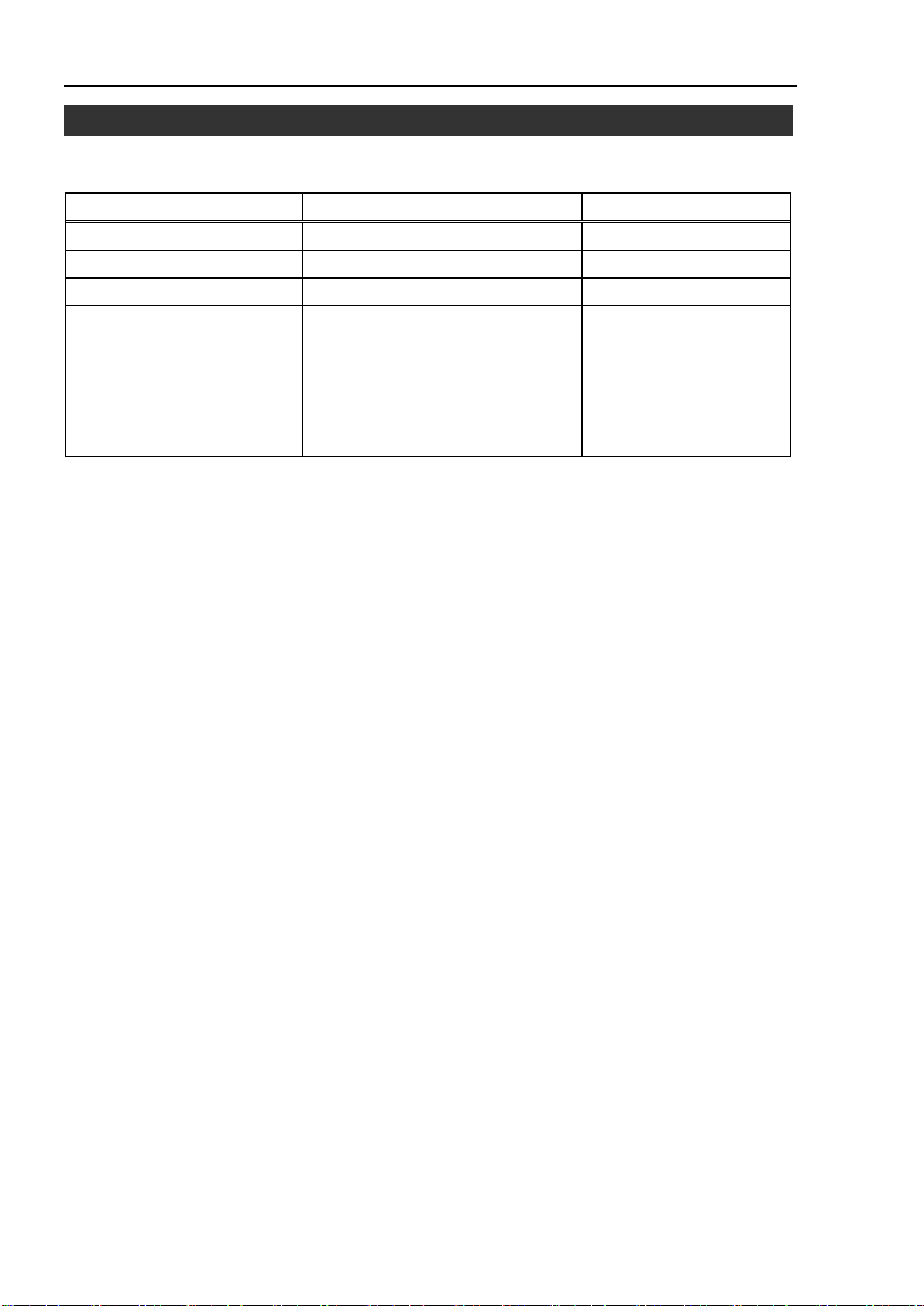
6. Maintenance Parts list
Terminal block
R12NZ900B6
R12R500DIO005
PG board connector
R12NZ900H2
R12R500PLS005
6. Maintenance Parts List
Specify the code when ordering maintenance parts.
Parts Name Code Old Code Note
PG (Pulse Generator) board R12NZ900A8 R12N748011
PG board cable R12NZ900BB R12R500PLS004
Pulse Generating Kit R12NZ900A9 R12N748041 PG (Pulse Generator) board
Plug, Cover
PG board cable
Connector (2)
Terminal block (2)
54 RC700 / RC90 option PG motion system Rev.5
 Loading...