

Page 1

Project Management and Development
Rev.1 EM111S2106F
EPSON RC+ 5.0
User's Guide
Ver.5.4
Page 2

EPSON RC+ 5.0 (Ver.5.4) User's Guide Project Management and Development Rev.1
Page 3

EPSON RC+ 5.0 (Ver.5.4)
User's Guide
Rev.1
Copyright © 2011 SEIKO EPSON CORPORATION. All rights reserved.
EPSON RC+ 5.0 (Ver.5.4) User's Guide Rev.1
i
Page 4

FOREWORD
Thank you for purchasing our robot products.
This manual contains the information necessary for the correct use of the Manipulator.
Please carefully read this manual and other related manuals before installing the robot
system.
Keep this manual handy for easy access at all times.
WARRANTY
Warnings, Cautions, Usage:
The robot and its optional parts are shipped to our customers only after being subjected to
the strictest quality controls, tests, and inspections to certify its compliance with our high
performance standards.
Product malfunctions resulting from normal handling or operation will be repaired free of
charge during the normal warranty period. (Please ask your Regional Sales Office for
warranty period information.)
However, customers will be charged for repairs in the following cases (even if they occur
during the warranty period):
1. Damage or malfunction caused by improper use which is not described in the manual,
or careless use.
2. Malfunctions caused by customers’ unauthorized disassembly.
3. Damage due to improper adjustments or unauthorized repair attempts.
4. Damage caused by natural disasters such as earthquake, flood, etc.
1. If the robot or associated equipment is used outside of the usage conditions and product
specifications described in the manuals, this warranty is void.
2. If you do not follow the WARNINGS and CAUTIONS in this manual, we cannot be
responsible for any malfunction or accident, even if the result is injury or death.
3. We cannot foresee all possible dangers and consequences. Therefore, this manual
cannot warn the user of all possible hazards.
ii EPSON RC+ 5.0 (Ver.5.4) User's Guide Rev.1
Page 5

TRADEMARKS
Microsoft, Windows, and Windows logo are either registered trademarks or trademarks of
Microsoft Corporation in the United States and/or other countries. Other brand and
product names are trademarks or registered trademarks of the respective holders.
TRADEMARK NOTATION IN THIS MANUAL
Microsoft® Windows® XP Operating system
Microsoft® Windows® Vista Operating system
Microsoft® Windows® 7 Operating system
Throughout this manual, Windows XP, Windows Vista, and Windows 7 refer to above
respective operating systems. In some cases, Windows refers generically to Windows XP,
Windows Vista, and Windows 7.
NOTICE
No part of this manual may be copied or reproduced without authorization.
The contents of this manual are subject to change without notice.
Please notify us if you should find any errors in this manual or if you have any comments
regarding its contents.
INQUIRIES
Contact the following service center for robot repairs, inspections or adjustments.
If service center information is not indicated below, please contact the supplier office for
your region.
Please prepare the following items before you contact us.
- Your controller model and its serial number
- Your manipulator model and its serial number
- Software and its version in your robot system
- A description of the problem
SERVICE CENTER
EPSON RC+ 5.0 (Ver.5.4) User's Guide Rev.1
iii
Page 6

MANUFACTURER & SUPPLIER
TEL : +81-(0)266-61-1802
FAX : +81-(0)266-61-1846
Japan & Others
SEIKO EPSON CORPORATION
Suwa Minami Plant
Factory Automation Systems Dept.
1010 Fujimi, Fujimi-machi,
Suwa-gun, Nagano, 399-0295
JAPAN
SUPPLIERS
Factory Automation/Robotics
TEL : +1-562-290-5900
FAX : +1-562-290-5999
E-MAIL : info@robots.epson.com
Factory Automation Division
TEL : +49-(0)-2159-538-1391
FAX : +49-(0)-2159-538-3170
E-MAIL : robot.infos@epson.de
Factory Automation Division
TEL : +86-(0)-10-8522-1199
FAX : +86-(0)-10-8522-1120
Factory Automation Division
TEL : +886-(0)-2-8786-6688
FAX : +886-(0)-2-8786-6677
North & South America
Europe
China
Taiwan
EPSON AMERICA, INC.
18300 Central Avenue
Carson, CA 90746
USA
EPSON DEUTSCHLAND GmbH
Otto-Hahn-Str.4
D-40670 Meerbusch
Germany
EPSON China Co., Ltd
7F, Jinbao Building No. 89 Jinbao Street
Dongcheng District, Beijing,
China, 100005
EPSON Taiwan Technology & Trading Ltd.
14F, No.7, Song Ren Road, Taipei 110
Taiwan, ROC
iv EPSON RC+ 5.0 (Ver.5.4) User's Guide Rev.1
Page 7

TABLE OF CONTENTS
1. Introduction 1
1.1 Welcome to EPSON RC+ 5.0 .................................................................. 1
1.2 System Overview..................................................................................... 1
1.2.1 RC170 Controller ........................................................................ 2
1.2.2 Software ...................................................................................... 2
1.2.3 Simulator .................................................................................... 2
1.2.4 System Block Diagram ................................................................ 3
1.3 Software Version...................................................................................... 4
1.3.1 Version Confirmation ................................................................... 4
1.3.2 Restrictions by Version Combination........................................... 5
1.4 Options .................................................................................................... 7
1.5 Precautions When Using Windows Vista................................................. 7
Table of Contents
1.6 EPSON RC+ 3.x and 4.x Users ............................................................... 7
1.7 SPEL for Windows Users......................................................................... 7
1.8 Documentation......................................................................................... 8
2. Safety 9
2.1 Overview.................................................................................................. 9
2.2 Definitions ................................................................................................ 9
2.2.1 Robot Power ............................................................................... 9
2.2.2 Safeguard.................................................................................. 10
2.2.3 Operation Modes....................................................................... 10
2.2.4 Start Mode................................................................................. 10
2.2.5 Changing Operation Mode ........................................................ 11
2.2.6 Emergency Stop........................................................................ 11
2.2.7 Teach Control Device ................................................................ 11
2.3 Safety-related Requirements ................................................................. 12
2.4 Installation and Design Precautions....................................................... 13
2.4.1 Designing a Safe Robot System ............................................... 13
2.4.2 Robot System Installation, Start-up, and Testing....................... 15
2.5 Precautions regarding Robot Operation ................................................ 17
2.5.1 General Precautions.................................................................. 17
2.5.2 Automatic Operation.................................................................. 17
2.5.3 Teaching Robot Points .............................................................. 17
EPSON RC+ 5.0 (Ver.5.4) User's Guide Rev.1 v
Page 8

Table of Contents
2.5.4 Return to Automatic Operation ..................................................18
2.5.5 Program Verification ..................................................................18
2.5.6 Troubleshooting......................................................................... 18
2.5.7 Maintenance.............................................................................. 18
2.5.8 Backup of Projects and Controller .............................................19
2.6 End User Instruction Manual.................................................................. 19
2.7 End User Training .................................................................................. 19
3. Getting Started 20
3.1 Hardware Installation ............................................................................. 20
3.2 Software Installation............................................................................... 20
4. Operation 21
4.1 Simple Mode.......................................................................................... 21
4.2 System Power Up Procedure................................................................. 21
4.3 Starting EPSON RC+ 5.0....................................................................... 21
4.3.1 Startup sequence ......................................................................22
4.3.2 Startup Configuration................................................................. 22
4.3.3 Start Mode................................................................................. 22
4.3.4 Start Mode Dialog...................................................................... 22
4.3.5 Startup Mode: Program .............................................................23
4.3.6 Startup Mode: Auto.................................................................... 24
4.3.7 Auto Start................................................................................... 24
4.3.8 Windows Login .......................................................................... 25
4.3.9 Command Line Options ............................................................. 25
Starting EPSON RC+ 5.0 in Simple Mode...................................... 25
Starting EPSON RC+ 5.0 for a specific project............................... 25
Change the EPSON RC+ 5.0 startup mode ................................... 26
Disabling the EPSON RC+ 5.0 splash window............................... 26
4.3.10 Using Command Line Options................................................... 26
Running from the Windows Run Box .............................................. 26
Making startup icons for your projects ............................................ 26
4.4 Communications with Controller ............................................................27
4.4.1 Configuring Communications with the Controller....................... 27
4.4.2 USB Communications ............................................................... 27
4.4.3 Ethernet Communications .........................................................28
4.4.4 Connecting When Control Device is not PC.............................. 28
4.5 Writing your first program....................................................................... 30
vi EPSON RC+ 5.0 (Ver.5.4) User's Guide Rev.1
Page 9

Table of Contents
5. The EPSON RC+ 5.0 GUI 35
5.1 GUI Overview ........................................................................................ 35
5.2 Project Explorer Pane............................................................................ 36
5.2.1 Context Menu ........................................................................... 36
5.3 Status Window Pane.............................................................................. 36
5.4 Status Bar .............................................................................................. 37
5.5 Online Help ............................................................................................ 37
5.6 File Menu ............................................................................................... 38
5.6.1 New Command ....................................................................... 38
5.6.2 Open Command ...................................................................... 39
5.6.3 Close Command ....................................................................... 39
5.6.4 Save Command ........................................................................ 40
5.6.5 Save As Command.................................................................... 40
5.6.6 Save All Command.................................................................... 40
5.6.7 Restore Command .................................................................... 40
5.6.8 Rename Command ................................................................... 41
5.6.9 Delete Command ...................................................................... 41
5.6.10 Import Command ...................................................................... 42
5.6.11 Print Command ......................................................................... 43
5.6.12 Exit Command........................................................................... 44
5.7 Edit Menu............................................................................................... 44
5.7.1 Undo Command ........................................................................ 44
5.7.2 Redo Command ........................................................................ 44
5.7.3 Cut Command ........................................................................... 44
5.7.4 Copy Command ........................................................................ 44
5.7.5 Paste Command ....................................................................... 45
5.7.6 Find Command.......................................................................... 45
5.7.7 Find Next Command ................................................................. 46
5.7.8 Replace Command.................................................................... 46
5.7.9 Select All Command.................................................................. 47
5.7.10 Indent Command....................................................................... 47
5.7.11 Outdent Command.................................................................... 47
5.7.12 Comment Block Command ....................................................... 47
5.7.13 Uncomment Block Command.................................................... 47
5.7.14 Go To Definition Command ....................................................... 47
EPSON RC+ 5.0 (Ver.5.4) User's Guide Rev.1 vii
Page 10

Table of Contents
5.8 View Menu................................................................................................. 48
5.8.1 Project Explorer Command ....................................................... 48
5.8.2 Status Window Command ......................................................... 48
5.8.3 System History Command......................................................... 49
5.9 Project Menu ............................................................................................. 50
5.9.1 New Command.......................................................................... 50
5.9.2 Open Command ........................................................................ 51
5.9.3 Recent Projects Submenu ......................................................... 52
5.9.4 Close Command........................................................................ 52
5.9.5 Edit Command........................................................................... 52
5.9.6 Save Command......................................................................... 54
5.9.7 Save As Command.................................................................... 54
5.9.8 Rename Command ................................................................... 55
5.9.9 Import Command....................................................................... 56
5.9.10 Copy Command ........................................................................61
5.9.11 Delete Command ......................................................................62
5.9.12 Build Command......................................................................... 62
5.9.13 Rebuild Command..................................................................... 62
5.9.14 Synchronize Command .............................................................63
5.9.15 Properties Command ................................................................ 64
5.10 Run Menu .............................................................................................. 71
5.10.1 Run Window Command............................................................. 71
5.10.2 Operator Window Command .....................................................71
5.10.3 Step Into Command...................................................................71
5.10.4 Step Over Command................................................................. 72
5.10.5 Walk Command......................................................................... 72
5.10.6 Resume Command ...................................................................72
5.10.7 Stop Command.......................................................................... 72
5.10.8 Toggle Breakpoint Command ....................................................73
5.10.9 Clear All Breakpoints Command................................................ 73
5.10.10 Display Variables Command .....................................................73
5.10.11 Call Stack Command................................................................. 74
5.11 Tools Menu............................................................................................. 75
5.11.1 Robot Manager Command ........................................................ 75
Control Panel .................................................................................. 76
Jog and Teach ................................................................................ 77
Jog Controls .................................................................................... 77
How to jog ....................................................................................... 80
viii EPSON RC+ 5.0 (Ver.5.4) User's Guide Rev.1
Page 11

Table of Contents
Jogging in Teach Mode ................................................................... 81
How to teach points ......................................................................... 81
Saving or aborting your work........................................................... 82
Points............................................................................................... 82
Arch .................................................................................................83
Local ................................................................................................ 84
Tools ................................................................................................ 90
Arms ................................................................................................93
ECP .................................................................................................94
Box................................................................................................... 95
Plane................................................................................................ 96
Weight.............................................................................................. 97
Inertia............................................................................................... 98
XYZ Limits .......................................................................................99
Range ............................................................................................ 100
Home Config.................................................................................. 101
5.11.2 Task Manager Command ........................................................ 102
5.11.3 I/O Label Editor Command...................................................... 104
5.11.4 I/O Monitor Command ............................................................. 106
To open the I/O Monitor................................................................. 106
Using the I/O Monitor..................................................................... 106
Custom I/O Views.......................................................................... 107
5.11.5 Command Window Command ................................................ 108
To open the Command window..................................................... 108
To execute SPEL+ commands from the Command window......... 108
5.11.6 Macros Command................................................................... 109
5.11.7 Controller Command ............................................................... 110
Backup Controller ..........................................................................110
Restore Controller .........................................................................111
Export Controller Status ................................................................112
View Controller Status ................................................................... 113
Reset Controller............................................................................. 114
5.11.8 User Error Editor Command.................................................... 114
5.11.9 Simulator Command................................................................ 115
5.11.10 Vision Command ..................................................................... 115
5.12 Setup Menu ......................................................................................... 115
5.12.1 PC to Controller Communications Command.......................... 116
5.12.2 Controller Command ............................................................... 117
General Page ................................................................................ 117
Configuration Page........................................................................ 118
Preferences Page.......................................................................... 119
Options ..........................................................................................120
Simulator........................................................................................ 120
Robot Model ..................................................................................121
Robot Configuration....................................................................... 122
Robot Calibration .......................................................................... 123
Robot Amplifiers ............................................................................ 124
EPSON RC+ 5.0 (Ver.5.4) User's Guide Rev.1 ix
Page 12

Table of Contents
Inputs / Outputs............................................................................. 125
EtherNet/IP.................................................................................... 125
Remote Control ............................................................................. 126
RS232 ........................................................................................... 129
TCP/IP........................................................................................... 129
5.12.3 Preferences Command............................................................ 130
Startup........................................................................................... 130
Workspace .................................................................................... 133
Editor ............................................................................................. 134
Robot Manager: General............................................................... 135
Robot Manager: Jogging............................................................... 136
Run Window.................................................................................. 137
Command Window........................................................................ 138
Language ...................................................................................... 139
5.13 Window Menu ...................................................................................... 140
5.13.1 Cascade Command................................................................. 140
5.13.2 Tile Horizontal Command ........................................................140
5.13.3 Tile Vertical Command ............................................................ 141
5.13.4 Arrange Icons Command......................................................... 141
5.13.5 Close All Command .................................................................141
5.13.6 1, 2, 3 Command..................................................................... 142
5.13.7 Windows Command ................................................................142
5.14 Help Menu............................................................................................ 143
5.14.1 How Do I Command ................................................................143
5.14.2 Contents Command................................................................. 143
5.14.3 Index Command ......................................................................144
5.14.4 Search Command ................................................................... 144
5.14.5 Manuals Submenu .................................................................. 145
5.14.6 About EPSON RC+ 5.0 Command .......................................... 145
6 The SPEL+ Language 146
6.1 Overview .............................................................................................. 147
6.2 Program structure ................................................................................ 147
6.2.1 What is a SPEL+ program?..................................................... 147
6.2.2 Calling functions ...................................................................... 147
6.3 Commands and statements ................................................................. 148
6.4 Function and variable names ...............................................................148
6.5 Data types............................................................................................ 149
6.6 Operators............................................................................................. 149
6.7 Working with variables ......................................................................... 150
x EPSON RC+ 5.0 (Ver.5.4) User's Guide Rev.1
Page 13

Table of Contents
6.7.1 Variable scopes ....................................................................... 150
6.7.2 Local variables ........................................................................ 150
6.7.3 Module variables ..................................................................... 150
6.7.4 Global variables ...................................................................... 151
6.7.5 Global Preserve variables ....................................................... 151
6.7.6 Arrays...................................................................................... 152
6.7.7 Initial values ............................................................................ 152
6.7.8 Clearing variables.................................................................... 152
6.8 Working with strings............................................................................. 153
6.9 Multi-statements................................................................................... 154
6.10 Labels .................................................................................................. 154
6.11 Comments ........................................................................................... 154
6.12 Error handling ...................................................................................... 155
6.13 Multi-tasking......................................................................................... 157
6.14 Robot coordinate systems ................................................................... 158
6.14.1 Overview ................................................................................. 158
6.14.2 Robot Coordinate System ....................................................... 158
6.14.3 Local Coordinate Systems ...................................................... 161
6.14.4 Tool Coordinate Systems ........................................................ 161
6.14.5 ECP Coordinate Systems (Option).......................................... 162
6.15 Robot arm orientations......................................................................... 163
6.15.1 SCARA robot arm orientations ................................................ 163
6.15.2 6-Axis robot arm orientations .................................................. 164
6.15.3 RS series arm orientations ...................................................... 166
6.16 Robot motion commands ..................................................................... 169
6.16.1 Homing the robot..................................................................... 169
6.16.2 Point to point motion................................................................ 169
6.16.3 Linear motion .......................................................................... 169
6.16.4 Curves..................................................................................... 169
6.16.5 Joint motion............................................................................. 170
6.16.6 Controlling position accuracy .................................................. 170
6.16.7 CP Motion Speed / Acceleration and Tool Orientation ............. 170
6.16.8 PTP Speed / Acceleration for Small Distances ........................ 171
6.17 Working with robot points..................................................................... 172
6.17.1 Defining points ........................................................................ 172
6.17.2 Referencing points by name.................................................... 172
EPSON RC+ 5.0 (Ver.5.4) User's Guide Rev.1 xi
Page 14

Table of Contents
6.17.3 Referencing points with variables............................................ 172
6.17.4 Using points in a program........................................................ 173
6.17.5 Saving and loading Points .......................................................173
6.17.6 Point attributes ........................................................................173
6.17.7 Extracting and setting point coordinates.................................. 174
6.17.8 Alteration of points................................................................... 175
6.18 Input and output control ....................................................................... 176
6.18.1 Hardware I/O ...........................................................................176
6.18.2 Memory I/O.............................................................................. 176
6.18.3 I/O Commands ........................................................................ 176
6.19 Using Traps.......................................................................................... 177
6.20 Special Task......................................................................................... 178
6.20.1 Precautions to Use the Special Task ...................................... 178
6.20.2 Special Task Specification .......................................................179
6.20.3 Special Task Example.............................................................. 180
7 Building SPEL+ Applications 181
7.1 Designing Applications......................................................................... 181
7.1.1 Creating the simplest application............................................. 181
7.1.2 Application Layout ...................................................................181
Program......................................................................................... 181
Operator interface ......................................................................... 181
Safety interface ............................................................................. 182
Robot Points, Pallets, Tools, Locals ............................................. 182
Inputs and outputs......................................................................... 182
Peripherals .................................................................................... 182
7.2 Managing Projects ............................................................................... 183
7.2.1 Overview ................................................................................. 183
What is an EPSON RC+ 5.0 Project?........................................... 183
Why do you need projects? .......................................................... 183
What's in an EPSON RC+ 5.0 project?......................................... 183
The Default Project ....................................................................... 183
7.2.2 Creating a new project............................................................. 184
7.2.3 Configuring a project ............................................................... 184
Editing a project ............................................................................ 184
7.2.4 Building a project .....................................................................185
Status Pane................................................................................... 185
7.2.5 Making copies of projects ........................................................ 186
7.2.6 Backing up a project ................................................................ 186
7.2.7 Converting a simple mode project........................................... 186
xii EPSON RC+ 5.0 (Ver.5.4) User's Guide Rev.1
Page 15

Table of Contents
7.3 Editing Programs ................................................................................. 187
7.3.1 Program rules.......................................................................... 187
7.3.2 Typing in program code........................................................... 187
7.3.3 Syntax Help............................................................................. 188
7.3.4 Syntax Errors........................................................................... 189
7.4 Editing Points....................................................................................... 190
7.5 Running and Debugging Programs...................................................... 190
7.5.1 The Run Window..................................................................... 190
7.5.2 Debugging............................................................................... 194
7.6 The Operator Window.......................................................................... 198
7.6.1 Operator Window Configuration .............................................. 199
7.7 Using Remote Control ......................................................................... 199
8 Simulator 200
8.1 Simulator Functions ............................................................................. 200
8.1.1 Overview ................................................................................. 200
8.1.2 System condition ..................................................................... 201
8.2 Using the Simulator ............................................................................. 202
8.2.1 Using with sample ...................................................................202
8.2.2 Using with original system....................................................... 204
8.3 Description of Functions ...................................................................... 211
8.3.1 Simulator window structure ..................................................... 211
(1) Tool bar ....................................................................................211
(2) Layout Objects ......................................................................... 212
(3) Property Grid............................................................................ 213
(4) 2D Layout................................................................................. 217
(5) 3D Display................................................................................ 218
(6) Record / Playback ....................................................................219
8.3.2 Simulator Settings ................................................................... 220
8.3.3 Collision detection ................................................................... 222
8.3.4 Virtual controller ...................................................................... 224
8.3.5 Connection with RC170/RC180 controller .............................. 225
8.4 Specification and Restriction of Simulator............................................ 227
8.4.1 EPSON RC+ 5.0 package....................................................... 227
8.4.2 Specification and precaution of 3D display.............................. 227
8.4.3
Specification and precaution of Simulation
(program execution on PC) ................................................228
8.4.4 Specification and precaution of EPSON RC+ ......................... 230
EPSON RC+ 5.0 (Ver.5.4) User's Guide Rev.1 xiii
Page 16

Table of Contents
8.4.5 Restriction on SPEL+ command execution .............................. 230
8.4.6 Specification and precaution
of EPSON RC+ 5.0 Trial version ................................................ 232
9 Robot Configuration 233
9.1 Setting the Robot Model ...................................................................... 233
9.2 Calibrating the Robot ...........................................................................234
9.3 Changing Robot Parameters................................................................ 237
9.3.1 Saving robot configuration data............................................... 237
9.3.2 Loading robot configuration data ............................................. 237
10 Inputs and Outputs 238
10.1 Overview .............................................................................................. 238
10.2 I/O Commands ..................................................................................... 238
10.3 I/O Configuration .................................................................................. 239
10.4 Monitoring I/O ......................................................................................239
10.5 Virtual I/O............................................................................................. 239
11 Remote Control 240
11.1 Overview.............................................................................................. 240
11.2 Remote Control Input Output Configuration ......................................... 241
11.3 Control Device Configuration ...............................................................241
11.4 Auto Mode with Remote Control ..........................................................242
11.5 Teach Mode with Remote Control ........................................................ 242
11.6 Debugging Remote Control .................................................................242
11.7 Remote Inputs...................................................................................... 243
11.8 Remote Outputs................................................................................... 245
11.9 Remote Input Handshake Timing ......................................................... 247
11.10 Remote Ethernet.................................................................................. 249
12 RS-232 Communications 255
12.1 RS-232 Software Configuration ........................................................... 255
12.2 RS-232 Commands ............................................................................. 255
13 TCP / IP Communications 256
13.1 TCP/IP Setup .......................................................................................256
13.1.1 Ethernet Hardware .................................................................. 256
13.1.2 IP Addresses ........................................................................... 256
xiv EPSON RC+ 5.0 (Ver.5.4) User's Guide Rev.1
Page 17

Table of Contents
13.1.3 IP Gateway.............................................................................. 256
13.1.4 Testing Windows TCP/IP setup ............................................... 257
13.2 TCP/IP Software Configuration ............................................................ 258
13.3 TCP/IP Commands .............................................................................. 258
13.4 TCP/IP Example .................................................................................. 259
14 ECP Motion 260
14.1 Overview.............................................................................................. 260
14.1.1 How to move the arm with ECP motion ................................... 261
1. Setting the ECP .........................................................................261
2. Teaching.................................................................................... 262
3. Executing Motion .......................................................................262
15 Installing Controller Options 263
16 Software License Agreement 264
Appendix A: Software Installation A-1
Installing EPSON RC+ 5.0 Software...............................................................A-1
Appendix B: Automatic Processing of Project Import B-1
Project for EPSON RC+ 3.*/4.*.......................................................................B-1
Project for SPEL for Windows 2.*...................................................................B-3
EPSON RC+ 5.0 (Ver.5.4) User's Guide Rev.1 xv
Page 18

Table of Contents
xvi EPSON RC+ 5.0 (Ver.5.4) User's Guide Rev.1
Page 19

1. Introduction
1.1 Welcome to EPSON RC+ 5.0
Welcome to the EPSON RC+ 5.0 Project Management and Development Environment.
EPSON RC+ 5.0 is used to develop application software for the EPSON RC170/RC180
Robot Controller.
EPSON RC+ 5.0 features:
- Runs on Microsoft Windows XP, Windows Vista, and Windows 7.
- Integrated application development environment.
- Communicates with controller using USB or Ethernet.
- One PC can be used to manage several controllers.
- Multiple simultaneous sessions.
+
- SPEL
language that supports multi-tasking, robot motion control, I/O control, and networking.
- Controller I/O configuration.
- Controller TCP/IP and RS-232 communications setup.
programming language. A powerful, easy to use BASIC-like programming
1. Introduction
- Wizards for robot tools, local coordinate systems, robot calibration.
- Vision Guide option. Enables you to create a vision system using an EPSON smart
camera.
- VB Guide option. Enables you to control the system using Microsoft .NET programming
languages.
- ECP option supports CP motion relative to a fixed point.
1.2 System Overview
The EPSON RC+ 5.0 software is used on a PC that connects with the EPSON
RC170/RC180 Robot Controller. EPSON RC+ 5.0 can communicate with the Controller
using USB or Ethernet.
EPSON RC+ 5.0 and the Controller can be used in the following configurations:
- Slave System In this configuration, the Controller is a PLC or PC cell
- Stand Alone System In this configuration, a PC is used as a mini cell controller.
slave. EPSON RC+ 5.0 is only used to develop the
application. Once the object code is stored in the
controller, the PC is not required to be connected to the
Controller. The Controller is controlled by remote digital
I/O or Fieldbus.
EPSON RC+ 5.0 can be started in Auto mode to display a
simple operator window for the Controller. Or, the VB
Guide option can be used to control the Controller from
a .NET application.
- Offline Development System In this configuration, a PC is used to edit programs and
build projects on an offline computer.
- Simulation System EPSON RC+ 5.0 is used on a PC connected to an
Controller without a robot using virtual I/O. I/O
simulation tasks can be created to run the application
using simulated I/O.
EPSON RC+ 5.0 (Ver.5.4) User's Guide Rev.1 1
Page 20

1. Introduction
1.2.1 RC170/RC180 Controller
The RC170/RC180 Controller is a compact robot controller that can drive EPSON SCARA
and Pro Six robots.
Controller features:
- Small and compact, yet powerful.
- Built in motion drive system. The motion drive system can control one robot with up to
six motors.
- Includes standard digital I/O.
- Optional digital I/O expansion boards.
- Optional Fieldbus slave support for DeviceNet, EtherNetI/P, PROFIBUS-DP,
PROFINET, and CC-Link.
- Optional RS232 ports.
For detailed information on the Controller, refer to the RC170/RC180 controller manual.
1.2.2 Software
The EPSON RC+ 5.0 software is installed on the development PC or laptop. To
communicate with the controller, the PC must support USB 1.1 / 2.0 or Ethernet
communications. Using EPSON RC+ 5.0, you can develop application software for the
SPEL+ language that runs in the RC170/RC180 controller.
1.2.3 Simulator
Simulator functions enable easy robot motion check on your PC, which gives you
flexibility to consider the system layout, measure the operation time, and create the robot
programs.
They are useful in all the way from introduction stage of robot automation to launch of
robot system.
Simulator is supported from EPSON RC+ 5.0 Ver.5.4 or later.
For details, refer to 8. Simulator.
2 EPSON RC+ 5.0 (Ver.5.4) User's Guide Rev.1
Page 21
1. Introduction
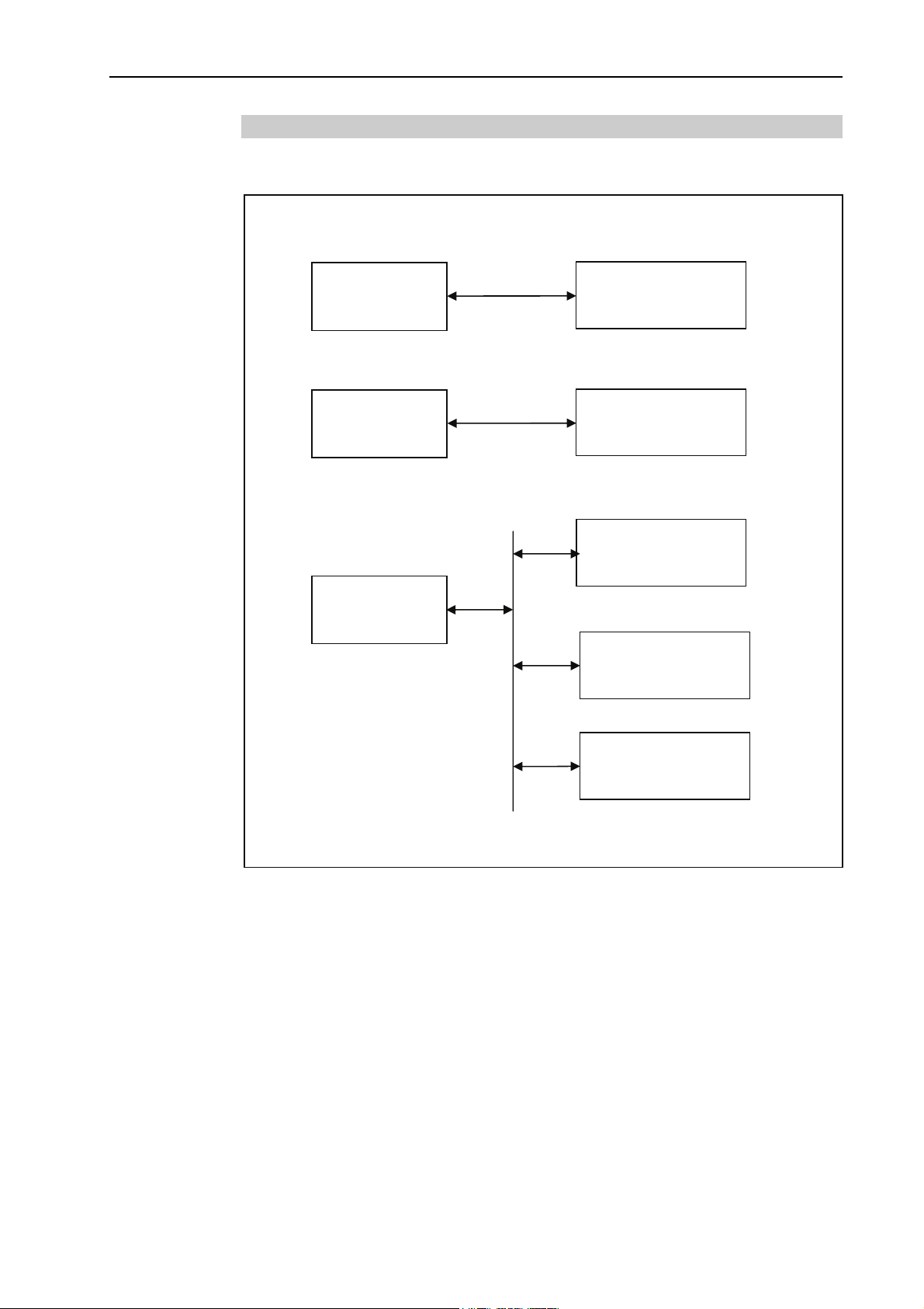
1.2.4 System Block Diagram
The following system block diagram shows different methods for connecting a PC running
EPSON RC+ 5.0 to one or more RC170/RC180 controllers.
Method 1: Connect PC to one controller using USB 1.1 or USB 2.0
PC
USB
RC170/RC180
Controller
Method 2: Connect PC to one controller using Ethernet
PC
Ethernet
RC170/RC180
Controller
Method 3: Connect PC to more than one controller using Ethernet.
RC170/RC180
Controller 1
PC
RC170/RC180
Controller 2
Ethernet
RC170/RC180
Controller 3
EPSON RC+ 5.0 (Ver.5.4) User's Guide Rev.1 3
Page 22
1. Introduction
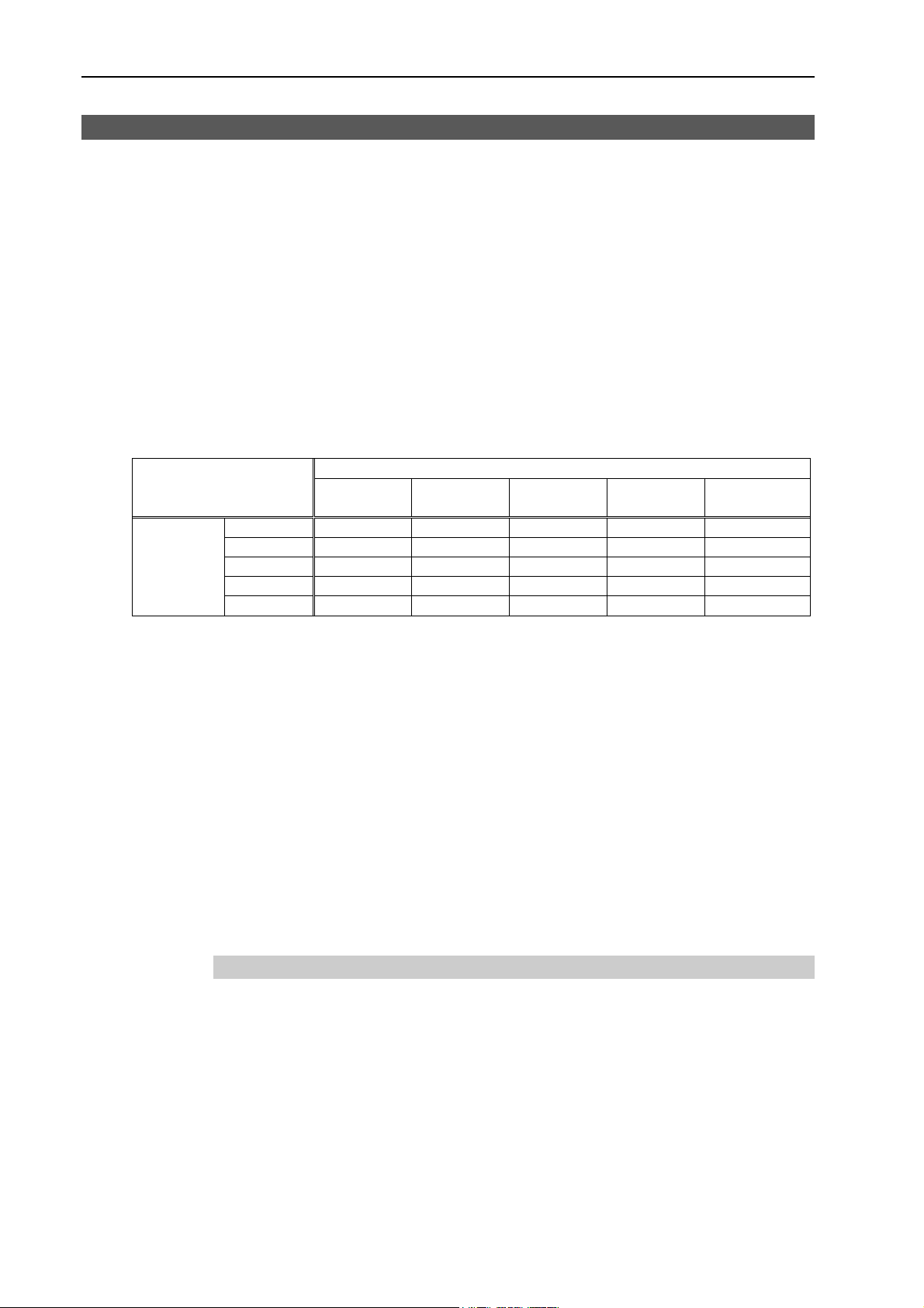
1.3 Software Version
There are five major software versions for EPSONRC+ 5.0.
Ver.5.0.*
Ver.5.1.*
Ver.5.2.*
Ver.5.3.*
Ver.5.4.*
RC170/RC180 firmware also has six major firmware versions.
Ver.1.0.*.*
Ver.1.2.*.*
Ver.1.4.*.*
Ver.1.6.*.*
Ver.1.8.*.*
Ver.1.10.*.*
You can connect a controller and PC with any major version combinations.
Ver.1.0.*.*
Ver.5.0.* OK *1 ! !! !! !!
EPSON
RC+ 5.0
Ver.5.1.* ! OK *2 !! !! !!
Ver.5.2.* ! ! OK *3 !! !!
Ver.5.3.*
Ver.5.4.*
OK: Compatible All functions of the EPSON RC+ 5.0 and the Controller are available.
*1 Refer to Ver.5.0 manuals.
*2 Refer to Ver.5.1 manuals.
*3 Refer to Ver.5.2 manuals.
*4 Refer to Ver.5.3 manuals.
!: Compatible Functions are partly limited.
!!: Compatible Functions are partly limited.
When using additional functions at the controller, EPSON RC+ 5.0 may
not display the proper dialog. The version update of EPSON RC+ 5.0 is
recommended.
The latest software version and firmware version are used for the description in this
manual.
EPSON RC+ 5.0 : Ver.5.4.*
Controller firmware : Ver.1.10.*.*
RC170/RC180 Controller Firmware Version
Ver.1.2.*.*
Ver.1.4.*.*
! ! !
! ! !
Ver.1.6.*.* Ver.1.8.*.* Ver.1.10.*.*
OK *4 !!
! OK
1.3.1 Version Confirmation
To confirm the EPSON RC+ 5.0 version, refer to 5.14.6 About EPSON RC+ 5.0 Command
(Help Menu).
To confirm the Controller firmware version, refer to 5.12.2 Controller Command (Setup
Menu).
4 EPSON RC+ 5.0 (Ver.5.4) User's Guide Rev.1
Page 23
1. Introduction
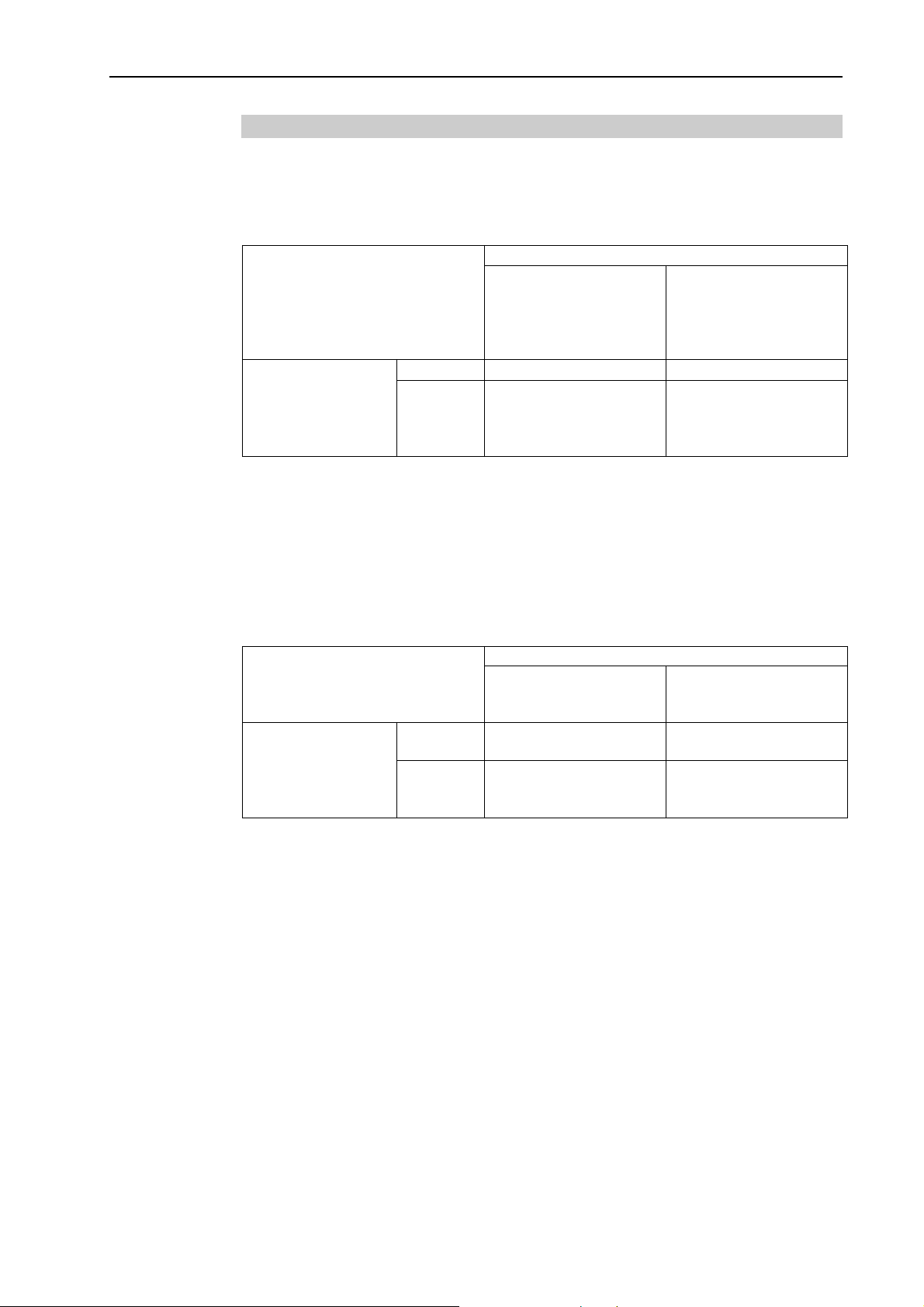
1.3.2 Restrictions for Version Combination
The functions are restricted according to the combination of the EPSON RC+ 5.0 and the
controller firmware.
Combination and Available Functions
EPSON RC+ 5.0 Ver.5.1.* or later / Controller firmware Ver.1.2.*.* or later
Ver.5.0.*
Ver.5.1.*
EPSON RC+ 5.0
OK : Available × : Not available
- Vision Guide option and command for Vision.
- EtherNet/IP option
- Select items for controller restore
- Setting “Safeguard open stops all tasks”
- TCPSpeed function
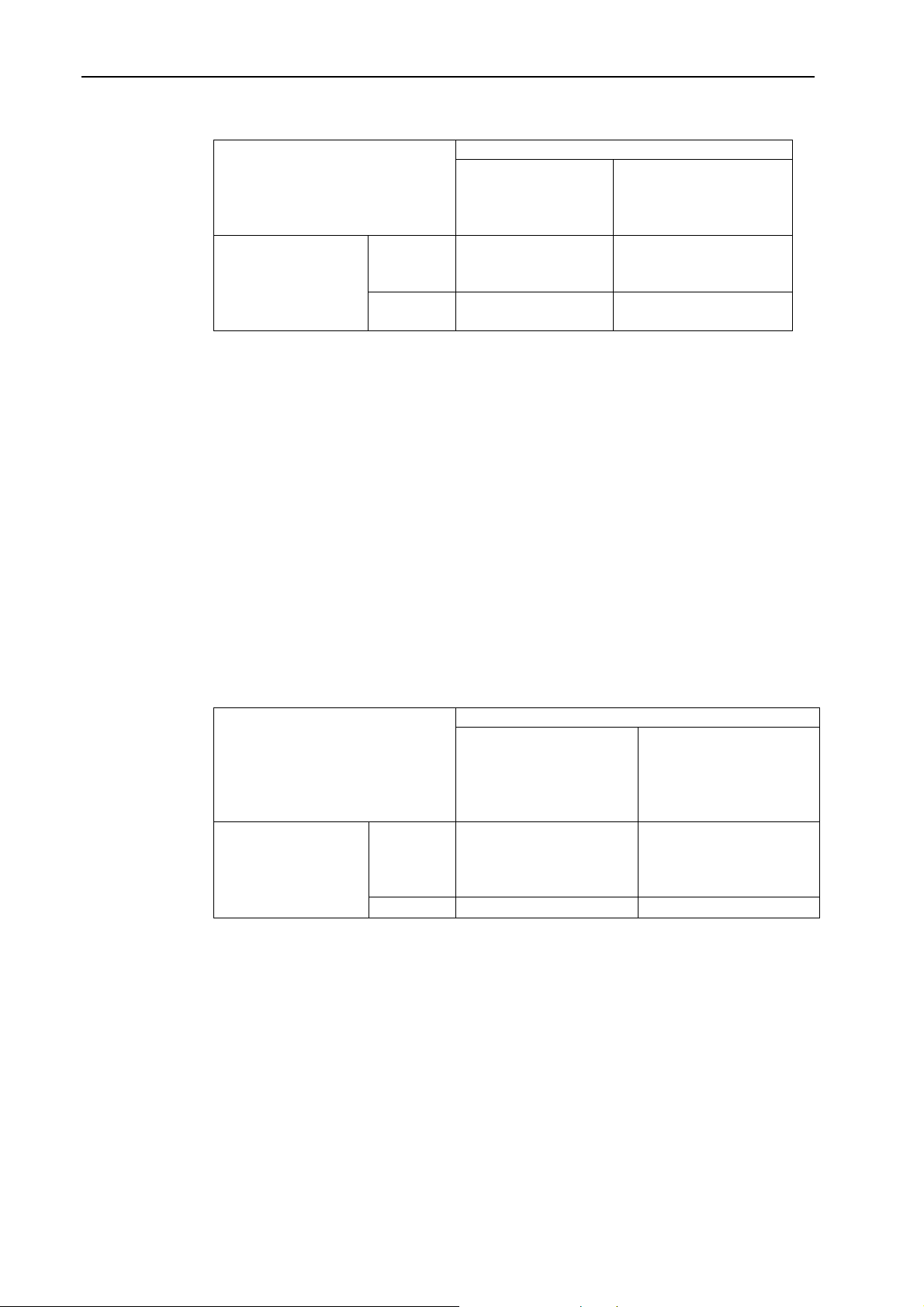
EPSON RC+ 5.0 Ver.5.2.* or later / Controller firmware Ver.1.6.*.* or later
EPSON RC+ 5.0
OK : Available × : Not available
Ver.5.2.*
Ver.5.3.*
Ver.5.4.*
Ver.5.0.*
Ver.5.1.*
Ver.5.2.*
Ver.5.3.*
Ver.5.4.*
RC170/RC180 Controller Firmware
Ver.1.2.*.*
Ver.1.4.*.*
Ver.1.0.*.*
× ×
×
RC170/RC180 Controller Firmware
Ver.1.0.*.*
Ver.1.2.*.*
Ver.1.4.*.*
× ×
×
Ver.1.6.*.*
Ver.1.8.*.*
Ver.1.10.*.*
OK
Ver.1.6.*.*
Ver.1.8.*.*
Ver.1.10.*.*
OK
- Task execution and monitoring of the following task types
NoPause NoEmgAbort
- Tool setting from 4 to 15
- Arm setting from 4 to 15
- Approach check area (Box) function
- Approach check plane (Plane) function
- Remote output for approach check area and approach check plane
- Following commands
AccelMax Function ErrorOn Function OLAccel Statement PlaneClr Statement
Box Statement EstopOn Function OLAccel Function PlaneDef Function
Box Function InsideBox Function PauseOn Function SaftyOn Function
BoxClr Statement InsidePlane Function Plane Statement SysErr Function
BoxDef Function LJM Function Plane Function
Forced keyword (On, Off, Out, OutW, OpBCD)
Normal, NoPause, NoEmgAbort keyword (Xqt)
EPSON RC+ 5.0 (Ver.5.4) User's Guide Rev.1 5
Page 24
1. Introduction
EPSON RC+ 5.0 Ver.5.3.* or later / Controller firmware Ver.1.8.*.* or later
RC170/RC180 Controller Firmware
Ver.1.0.*.*
Ver.1.2.*.*
Ver.1.4.*.*
Ver.1.8.*.*
Ver.1.10.*.*
Ver.1.6.*.*
Ver.5.0.*
EPSON RC+ 5.0
Ver.5.1.*
Ver.5.2.*
Ver.5.3.*
Ver.5.4.*
× ×
×
OK *1
OK : Available × : Not available
- RS series support
- Remote Ethernet function
- Following commands
TC Statement TCLim Statement TCLim Function
TCSpeed Statement TCSpeed Function RealTorque Statement
J1Flag Statement J1Flag Function J2Flag Statement J2Flag Function
*1 EPSON RC+ 5.0 Ver.5.3.4 or greater and the controller firmware Ver.1.8.5.0 or greater
enable the following functions:
- Go, Pass, Jump3, Jump3CP - LJM parameter support
- InReal, OutReal, SetInReal commands
- SysErr parameter support
- AtHome Function
EPSON RC+ 5.0 Ver.5.4.* or later / Controller firmware Ver.1.10.*.* or later
RC170/RC180 Controller Firmware
Ver.1.0.*.*
Ver.1.2.*.*
Ver.1.4.*.*
Ver.1.10.*.*
Ver.1.6.*.*
Ver.1.8.*.*
Ver.5.0.*
EPSON RC+ 5.0
Ver.5.1.*
Ver.5.2.*
× ×
Ver.5.3.*
Ver.5.4.*
×
OK
OK : Available × : Not available
- Simulator function
- Chinese support (Simplified / Traditional)
- Remote input of ForcePowerLow
- Remote input of PowerHigh
- Following commands
QPDecelR QPDecelS ElapsedTime function
QPDecelR function QPDecelS function ResetElapsedTime
6 EPSON RC+ 5.0 (Ver.5.4) User's Guide Rev.1
Page 25

1.4 Options
You can purchase options that must be enabled in the controller. EPSON RC+ 5.0 is used
to enable these options. See the chapter 15. Installing Controller Options for details.
1.5 Precautions When Using Windows Vista / Windows 7
Connecting development PC to robot controller using Ethernet
The robot controller does not support internet protocol version 6 (TCP/IPv6). When
connecting the development PC to the robot controller using the Ethernet, be sure to use
internet protocol version 4 (TCP/IPv4).
Cannot find camera in the network using camera search
When the Network discovery is OFF, you cannot find the camera in the network using the
camera search. Make sure that the Network discovery is ON.
For details, refer to the EPSON RC+5.0 Option: Vision Guide 5.0 manual.
For Windows Vista
Set the Network discovery ON from [Control Panel]-[Network and Internet]-[Network
and Sharing Center] in Windows.
1. Introduction
For Windows 7
Set the Network discovery ON from [Control Panel]-[Network and Internet]-[Network
and Sharing Center]-[Change advanced sharing settings] in Windows.
1.6 EPSON RC+ 3.x and 4.x Users
If you have used previous 3.x and 4.x versions of EPSON RC+ software, you will find that
EPSON RC+ 5.0 is very similar.
You can convert your previous EPSON RC+ projects by using Project | Import. EPSON
RC+ 5.0 will copy the entire project from the \EPSONRC\Project directory to the
\EpsonRC50\Project directory. You can then use the project in the EPSON RC+ 5.0
environment.
1.7 SPEL for Windows Users
If you have used SPEL for Windows 1.x or 2.x software, you will find that EPSON RC+
5.0 is very similar.
Many new commands have been added to the SPEL
Also, several commands were made obsolete or replaced.
You can convert your SPEL for Windows 2.x project by using Project | Import. EPSON
RC+ 5.0 will copy the files to a new directory and optionally convert the programs.
+
language, which replaces SPEL.
EPSON RC+ 5.0 (Ver.5.4) User's Guide Rev.1 7
Page 26

1. Introduction
1.8 Documentation
All documentation is installed on the PC in Adobe PDF format. To view manuals on the
PC, select Manuals from the Help Menu in EPSON RC+ 5.0. You can also access the
manuals from the Windows desktop by clicking Start - Programs - EPSON RC+ 5.0 and
click on the manual you want to view.
EPSON RC+ 5.0 User's Guide
This manual contains detailed information for the entire system.
SPEL
This manual contains detailed information for the entire SPEL
Vision Guide 5.0 Manual
This manual contains information for using the Vision Guide 5.0 option.
VB Guide 5.0 Manual
This manual contains information for using the VB Guide 5.0 option.
Robot Manual
This manual contains detailed information for the robot you have purchased. Each series
of robots has its own manuals.
+
Language Reference Manual
+
language.
NOTE
)
TIP
)
The “NOTE” sections describe important information to be
followed for operating the Robot system.
The "TIP" sections describe hints for easier or alternative
operations.
8 EPSON RC+ 5.0 (Ver.5.4) User's Guide Rev.1
Page 27
2. Safety
2.1 Overview
2. Safety
This chapter explains the important safety requirements for robotic systems using EPSON
RC+ 5.0 and the Controller.
Installation of robots and robotic equipment should only be performed by qualified
personnel in accordance with national and local codes. Please read and understand this
entire chapter before using your EPSON RC+ 5.0 system.
Remember that safety is the most important consideration when designing and operating
any robotic system.
2.2 Definitions
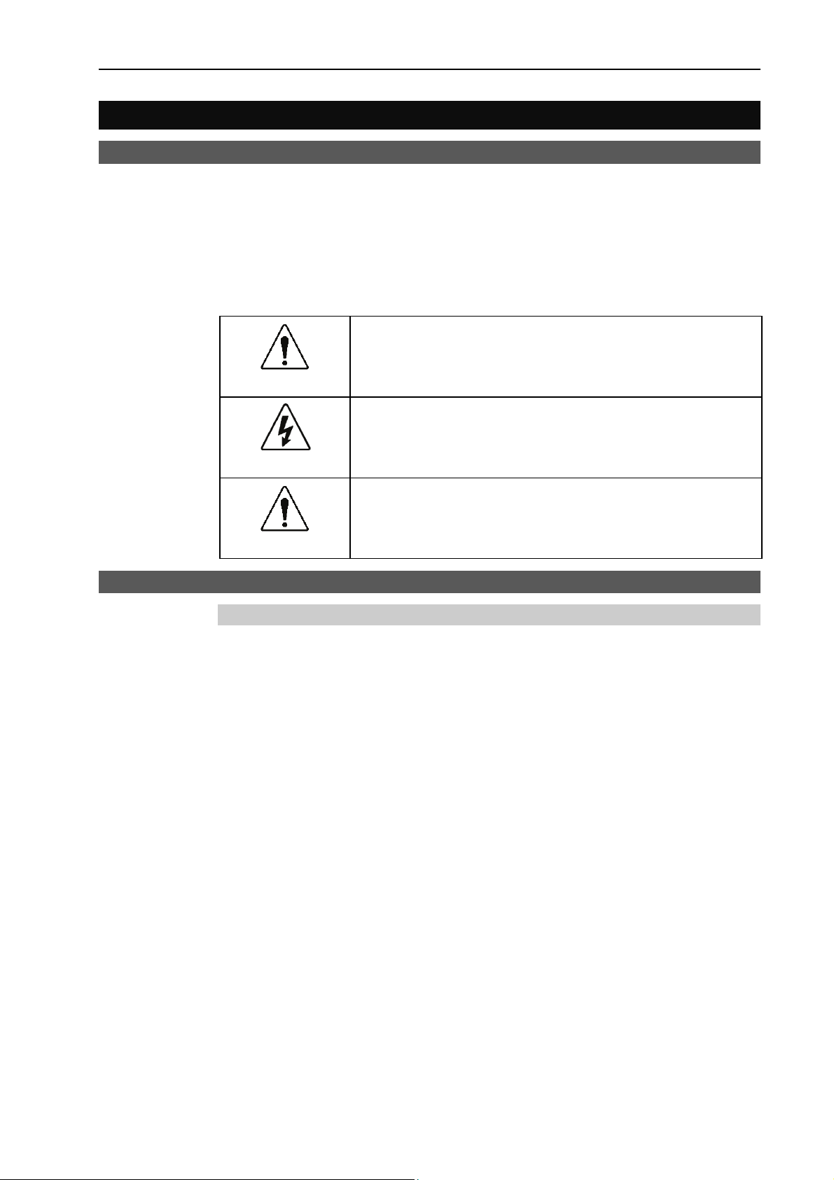
bol indicates that a danger of possible serious injury or
WARNING
WARNING
CAUTION
This sym
death exists if the associated instructions are not followed
properly.
This symbol indicates that a danger of possible harm to people
caused by electric shock exists if the associated instructions are
not followed properly.
This symbol indicates that a danger of possible harm to people or
physical damage to equipment and facilities exists if the
associated instructions are not followed properly.
2.2.1 Robot Power
The status of robot power is explained below in terms of restriction to operation:
Operation-prohibited status: Robot cannot be operated.
Restricted (low power) status: Robot can operate at low speed and low torque.
Unrestricted (high power) status: Robot can operate without restriction.
The robot will not operate regardless of the control actions taken by the operator when in
the operation-prohibited state. During operation, when the safeguard circuit opens, the
system will switch to operation-prohibited state.
The robot will operate at low speed and torque in the restricted state (low power). In the
unrestricted state (high power), the robot will operate at the programmed speed and torque.
In the event that the robot should make an unexpected movement, the restricted state (low
power) decreases operating speed allowing the operator to avoid danger. The torque is
also decreased to minimize serious injury to the operator should one be struck by the robot.
The maximum values of the decreased speed and torque are set according to the robot used
and cannot be changed by the user.
As a safety precaution the initial power state of the robot will be set to either the restricted
(low power) state or the operation-prohibited state. The system will not change to the
unrestricted (high power) state if the appropriate procedures are not followed.
When the system is in restricted (low power) state or operation-prohibited state, a single
failure will not cause a runaway action that surpasses the assigned speed or torque decrease.
This is due to the multi-protect circuit and mutual monitoring circuit in the control system.
EPSON RC+ 5.0 (Ver.5.4) User's Guide Rev.1 9
Page 28

2. Safety
WARNING
2.2.2 Safeguard
To ensure safe operation of the robotic work cell, you must install a safety system using
safety doors, light curtains, safety floor mats, etc.
■
There is a safeguard input circuit in the EMERGENCY connector on the
controller that connects with the safety device interlock switch. In order to protect
those working with the robot be sure that the interlock switch is connected and
working properly.
If a closed safeguard is open during robot motion, the robot stops immediately and enters
pause state. All robot motors are turned off. The descriptions below explain how the
safeguard input works.
Safeguard closed: The safeguard input is turned ON. The robot can automatically
operate in unrestricted (high power) state.
Safeguard open: The safeguard input is turned OFF, and the interlock function
operates. The robot stops immediately, motors are turned off, and
further operation is impossible until either the safeguard is closed or
Teach mode is turned ON and the enable circuit is engaged.
For further details on the safeguard and interlock, refer to the section Installation and
Design Precautions later in this chapter. For detailed wiring instructions, refer to the Setup
& Operation EMERGENCY in the controller manual.
2.2.3 Operation Modes
The operation mode is defined as the single control point for the controller, therefore you
cannot use more than one operation mode at the same time.
There are three operation modes for the controller: AUTO, PROGRAM, and TEACH.
- AUTO operation modes allow you to execute programs in the controller when the
safeguard is closed.
- PROGRAM operation mode allows you to execute and debug programs when the
safeguard is closed.
- TEACH operation mode allows you to jog and teach the robot at slow speed while inside
the safeguarded area.
2.2.4 Start Mode
The Start mode specifies the operation mode for EPSON RC+ 5.0 when it starts.
You can set the EPSON RC+ 5.0 to start in AUTO or PROGRAM mode.
For information on how to change the start mode, refer to the Operation chapter.
10 EPSON RC+ 5.0 (Ver.5.4) User's Guide Rev.1
Page 29
2. Safety
2.2.5 Changing Operation Mode
You can change from AUTO operation mode or PROGRAM operation mode to TEACH
mode by setting the mode selector key switch on the Teach Pendant to the TEACH
position.
When the mode selector key switch is changed back to AUTO, the operation mode is
returned to previous operation mode (AUTO or PROGRAM).
The AUTO operation mode can be changed to PROGRAM mode during the EPSON RC+
5.0 startup sequence. A password can be used to allow only certain personnel to change
the startup operation mode.
When EPSON RC+ 5.0 starts in AUTO operation mode, the AUTO operation mode cannot
be changed to PROGRAM operation mode after the system has started. To change the
operation mode, restart the system and log into PROGRAM mode, then set the start mode
again and restart EPSON RC+ 5.0.
For more information, refer to the Operation chapter.
2.2.6 Emergency Stop
The controller is equipped with an emergency stop input terminal. If the normally closed
emergency stop circuit is broken, the power supplied to all motors will be shut off (and
enter servo-free status) and the robot will be stopped by dynamic braking.
CAUTION
■
The path that the robot will follow from the time the emergency stop switch is
pressed until the device stops, as well as the stop position itself, cannot be
positively determined. In many cases, the stop position will not exceed the
target position for the operation prior the emergency stop. Depending on the
robot’s loading condition and operation speed, overruns are inevitable. Taking
this into consideration, be sure the layout for the peripheral equipment includes
extra space.
For detailed wiring instructions, refer to the section EMERGENCY in the controller manual.
2.2.7 Teach Control Device
Operators can use the TP1 teach pendant to operate the robot in the TEACH operation
mode.
Refer to the TP1 manual for operation instructions.
EPSON RC+ 5.0 (Ver.5.4) User's Guide Rev.1 11
Page 30

2. Safety
2.3 Safety-related Requirements
Specific tolerances and operating conditions for safety are contained in the manuals for the
robot, controller and other devices. Be sure to read those manuals as well.
For the installation and operation of the robot system, be sure to comply with the
applicable local and national regulations.
Robot systems safety standards and other examples are given in this chapter. Therefore, to
ensure that safety measures are complete, please refer to the other standards listed as well.
(Note: The following is only a partial list of the necessary safety standards.)
EN775 European Standard; Manipulating industrial robots - Safety.
ANSI/RIA R15.06 American National Standard; Industrial Robots and Robot
IEC204-1 (EN60204-1) Safety of machinery - Electrical equipment of machines
Part 1. Specification for general requirements.
EN292-1,-2 Safety of machinery - Basic concepts, general principles for
Systems - Safety Requirements .
design
Part 1. Basic terminology, methodology
Part 2. Technical principles and specifications
EN418 Emergency stop equipment, functional aspects - principles for
design.
EN953 General requirements for design and construction of guards.
EN55011 Limits and methods of measurement of radio disturbance
characteristic of industrial scientific and medical (ISM) radio
frequency equipment
EN61000-6-2 Electromagnetic compatibility (EMC)
Part 6-2. Generic standards - Immunity for industrial
environments
EN1050 Safety of machinery Principles for risk assessment
EN954-1 Safety of machinery-Safety related parts of control systems
UL Specification
Compatibility assessment of the UL specification model is performed according to the
following standards.
UL1740 (Third Edition, Dated December 7, 2007)
ANSI/RIA R15.06-1999
NFPA 79 (2007 Edition)
CSA/CAN Z434-03 (February 2003)
12 EPSON RC+ 5.0 (Ver.5.4) User's Guide Rev.1
Page 31

2.4 Installation and Design Precautions
2.4.1 Designing a Safe Robot System
It is important to operate robots safely. It is also important for robot users to give careful
consideration to the safety of the overall robot system design.
This section summarizes the minimum conditions that should be observed when using
EPSON robots in your robot systems.
Please design and manufacture robot systems in accordance with the principles described
in this and the following sections.
Environmental Conditions
Carefully observe the conditions for installing robots and robot systems that are listed in
the “Environmental Conditions” tables included in the manuals for all equipment used in
the system.
System Layout
When designing the layout for a robot system, carefully consider the possibility of error
between robots and peripheral equipment. Emergency stops require particular attention,
since a robot will stop after following a path that is different from its normal movement
path. The layout design should provide enough margin for safety. Refer to the manuals
for each robot, and ensure that the layout secures ample space for maintenance and
inspection work.
2. Safety
When designing a robot system to restrict the area of motion of the robots, do so in
accordance with the methods described in each robot manual. Utilize both software and
mechanical stops as measures to restrict motion.
Install the emergency stop switch at a location near the operation unit for the robot system
where the operator can easily press and hold it in an emergency.
Do not install the controller at a location where water or other liquids can leak inside the
controller. In addition, never use liquids to clean the controller.
Disabling Power to the System using lock out / tag out
The power connection for the robot controller should be such that it can be locked and
tagged in the off position to prevent anyone from turning on power while someone else is
in the safeguarded area. For further details, refer to the section Procedure of
Lockout/Tagout in the chapter Safety Precautions in the controller manual.
End Effector Design
Provide wiring and piping that will prevent the robot end effector from releasing the object
held (the work piece) when the robot system power is shut off.
Design the robot end effector such that its weight and moment of inertia do not exceed the
allowable limits. Use of values that exceed the allowable limits can subject the robot to
excessive loads. This will not only shorten the service life of the robot but can lead to
unexpectedly dangerous situations due to additional external forces applied to the end
effector and the work piece.
Design the size of the end effector with care, since the robot body and robot end effector
can interfere with each other.
EPSON RC+ 5.0 (Ver.5.4) User's Guide Rev.1 13
Page 32

2. Safety
Peripheral Equipment Design
When designing equipment that removes and supplies parts and materials to the robot
system, ensure that the design provides the operator with sufficient safety. If there is a
need to remove and supply materials without stopping the robot, install a shuttle device or
take other measures to ensure that the operator does not need to enter a potentially
dangerous zone.
Ensure that an interruption to the power supply (power shutoff) of peripheral equipment
does not lead to a dangerous situation. Take measures that not only prevent a work piece
held from being released as mentioned in “End effector Design” but that also ensure
peripheral equipment other than the robots can stop safely. Verify equipment safety to
ensure that, when the power shuts off, the area is safe.
Remote Control
To prevent operation by remote control from being dangerous, start signals from the
remote controller are allowed only when the control device is set to REMOTE, TEACH
mode is OFF, and the system is configured to accept remote signals. Also when remote is
valid, motion command execution and I/O output are available only from remote. For the
safety of the overall system, however, safety measures are needed to eliminate the risks
associated with the start-up and shutdown of peripheral equipment by remote control.
Emergency Stop
Each robot system needs equipment that will allow the operator to immediately stop the
system’s operation. Install an emergency stop device that utilizes emergency stop input
from the controller and all other equipment.
During an emergency stop, the power that is supplied to the motor driving the robot is shut
off, and the robot is stopped by dynamic braking.
The emergency stop circuit should also remove power from all external components that
must be turned off during an emergency. Do not assume that the robot controller will turn
off all outputs if configured to. For example, if an I/O card is faulty, the controller cannot
turn off a component connected to an output. The emergency stop on the controller is
hardwired to remove motor power from the robot, but not external power supplies.
Safeguard System
To ensure safety, a safeguard system should be installed for the robot system.
When installing the safeguard system, strictly observe the following points:
Refer to each robot manual, and install the safeguard system outside the maximum space.
Carefully consider the size of the end effector and the work pieces to be held so that there
will be no error between the moving parts and the safeguard system.
Manufacture the safeguard system to withstand calculated external forces (forces that will
be added during operation and forces from the surrounding environment).
When designing the safeguard system, make sure that it is free of sharp corners and
projections, and that the safeguard system itself is not a hazard.
Make sure that the safeguard system can only be removed by using a tool.
There are several types of safeguard devices, including safety doors, safety barriers, light
curtains, safety gates, and safety floor mats. Install the interlocking function in the
safeguard device. The safeguard interlock must be installed so that the safeguard interlock
is forced to work in case of a device failure or other unexpected accident. For example,
when using a door with a switch as the interlock, do not rely on the switch’s own spring
force to open the contact. The contact mechanism must open immediately in case of an
accident.
14 EPSON RC+ 5.0 (Ver.5.4) User's Guide Rev.1
Page 33

2. Safety
Connect the interlock switch to the safeguard input of the drive unit’s EMERGENCY
connector. The safeguard input informs the robot controller that an operator may be inside
the safeguard area. When the safeguard input is activated, the robot stops immediately and
enters pause status, as well as either operation-prohibited status or restricted status (low
power status).
Make sure not to enter the safeguarded area except through the point where the safeguard
interlock is installed.
The safeguard interlock must be installed so that it can maintain a safe condition until the
interlock is released on purpose once it initiates. The latch-release input is provided for the
EMERGENCY connector on the Controller to release the latch condition of the safeguard
interlock. The latch release switch of the safeguard interlock must be installed outside of
the safeguarded area and wired to the latch-release input.
It is dangerous to allow someone else to release the safeguard interlock by mistake while
the operator is working inside the safeguarded area. To protect the operator working inside
the safeguarded area, take measures to lock out and tag out the latch-release switch.
Presence Sensing Device
The above mentioned safeguard interlock is a type of presence sensing device, since it
indicates the possibility of somebody being inside the safeguard system. When separately
installing a presence sensing device, however, perform a satisfactory risk assessment and
pay thorough attention to its dependability.
Here are precautions that should be noted:
- Design the system so that when the presence sensing device is not activated or a
dangerous situation still exists that no personnel can go inside the safeguard area or place
their hands inside it.
- Design the presence sensing device so that regardless of the situation the system operates
safely.
- If the robot stops operating when the presence sensing device is activated, it is necessary
to ensure that it does not start again until the detected object has been removed. Make
sure that the robot cannot automatically restart.
Resetting the Safeguard
Ensure that the robot system can only be restarted through careful operation from outside
the safeguarded system. The robot will never restart simply by resetting the safeguard
interlock switch. Apply this concept to the interlock gates and presence sensing devices
for the entire system.
Robot Operation Panel
When using the robot operation panel, it must be installed so as to operate the robot system
from outside the safeguard.
EPSON RC+ 5.0 (Ver.5.4) User's Guide Rev.1 15
Page 34

2. Safety
2.4.2 Robot System Installation, Start-up, and Testing
Installation
When installing the robot and robot system, follow the instructions contained in each of the
robot and robot system manuals.
Start-up and Functional Testing
If the safeguard system is not ready at the time of start-up and functional testing, specify an
area to install the safeguard system (as a temporary measure) and then begin.
During start-up and functional testing, do not allow workers inside the safeguarded area
until the safeguard function is activated.
Before start-up and functional testing, carefully read the related manuals and obtain a good
understanding of safety-related precautions.
Before supplying the robot and robot system with power for the first time, verify the items
listed below.
Items to check before supplying with power
- Prescribed bolts are securely tightened to the robot.
- Electrical connections are set up correctly, and power supply conditions (including
voltage, frequency, and error level) are within the specified range.
- Compressed air source (if applicable) is properly connected.
- Peripheral devices are properly connected.
- Safety device is equipped with an interlock switch, and it functions properly.
- Operating environment conditions conform to the conditions specified in the robot and
controller manuals.
Items to check after supplying with power
- Start/stop, mode selection, and other functions work properly.
- Moving axes operate normally, and that the area of motion is limited as stipulated in the
specifications.
- Emergency stop circuit functions correctly.
- Power supply can be shut off.
- Teach operation mode is functioning properly.
- Safety device and interlock switch function correctly.
- Other safeguards (if applicable) are installed correctly in their prescribed locations.
- Robot operates accurately in restricted status (low power status).
- Robot operates properly under rated loads and at maximum speed.
Restarting after a Change
When restarting the robot system after its hardware or software has been corrected or
serviced, strictly observe the following:
- Before supplying the system with power, check the locations where the hardware was
modified.
- Test the functions of the robot system to make sure that it operates correctly.
16 EPSON RC+ 5.0 (Ver.5.4) User's Guide Rev.1
Page 35

2.5 Precautions regarding Robot Operation
2.5.1 General Precautions
Before operation, become familiar with the location of all emergency stop switches.
During an emergency, always press the nearest emergency stop switch. There should
never be any emergency stop switches in the system that do not operate.
After an emergency, do not restore the emergency stop circuit until it has been determined
that the entire system is safe to restart.
If your robot is a 6-Axis type, record the pulse values of the reference points used for
calibration. For details, refer to the section Setup & Operation 3.6 Setting the Reference
Points for Calibration in the 6-Axis manipulator manual.
2.5.2 Automatic Operation
Ensure that system automatic operation is enabled only while the following requirements
are being met:
- Emergency stop switches are installed in the prescribed location and operate correctly.
- No personnel are inside the safeguarded area of the system.
2. Safety
- Safety procedures that are established separately for the robot system (if applicable) are
being followed.
2.5.3 Teaching Robot Points
If possible, teaching should be performed with no personnel inside the safeguarded area.
Teach mode can be used to allow the robot to be jogged or moved at slow speed when the
safeguard is open. Before going inside the safeguarded area, robot operators that need to
move the robot under servo control must switch Teach mode to ON by using the mode
selector key switch of the teach pendant. Operators then carry the teach pendant while
inside the safeguarded area. As a result, the operation mode cannot be changed from
outside the safeguarded system while somebody is inside the safeguarded area.
Auto Mode and Program Mode
the safeguard circuit open, the robot motors will be turned off and the robot cannot be
With
jogged under power. However, the robot can be moved by hand to a position with the
safeguard circuit open and the position can then be taught.
Teach Mode
The ro
bot can be jogged or moved at slow speed as long as the three position enable (dead
man) switch is engaged.
Please observe the following guidelines for teaching points:
- Robot operators must receive training that utilizes the same type of robot. Before
teaching, the operator should be thoroughly familiar with teaching procedures.
- Before teaching, remove all errors and malfunctions.
- Before the robot operator goes inside the safeguard system, confirm that the robot motors
go off when the safeguard is open and that emergency stop switches are functioning
correctly.
- The robot operator should visually check the robot system and safeguard system interior
to ensure that there are no potential hazards.
- Design the system in such a way that prevents the overall robot system from being started
up from any location while the operator is inside the safeguarded area.
EPSON RC+ 5.0 (Ver.5.4) User's Guide Rev.1 17
Page 36

2. Safety
- If there is a possibility of a dangerous situation arising from the operation of a device
other than the robot, such as an actuator, take steps to prevent such operation or ensure
that these devices can only be controlled by the teaching operator.
2.5.4 Return to Automatic Operation
If there are safety devices that have been temporarily disabled for system inspection or
other reasons, always return them to their original status before restarting automatic
operation.
2.5.5 Program Verification
If it is necessary to verify a program while the system is in unrestricted (high power) status,
first make sure that no personnel are inside the safeguarded area.
2.5.6 Troubleshooting
Troubleshoot from outside the safeguard system. If that is not possible, strictly observe the
requirements below.
- Operators responsible for troubleshooting should be trained and qualified to perform such
work.
- Establish work safety procedures to minimize the danger that operators inside the
safeguard system will be exposed to.
2.5.7 Maintenance
In order to keep the robot and robot system operating safely, maintenance (and inspection)
is important. Adequately trained personnel should perform the procedures required to do
the maintenance work safely. Make sure that maintenance is performed according to the
instructions in the robot and controller manuals (maintenance editions).
If maintenance is required inside the safeguarded area, take the following precautions:
- Shut off the power supply using lockout / tagout to prevent anyone from turning ON the
robot power supply by mistake. For further details, refer to the section Procedure of
Lockout/Tagout in the chapter Safety Precautions in the controller manual.
- If the robot system power supply cannot be shut off, strictly observe the following:
(1) Visually inspect the robot system to ensure that there are no conditions that could lead
to a malfunction.
(2) If it is discovered that the robot system is damaged or malfunctioning, perform the
required repairs and retest it before allowing the operator to go inside the safeguard
system.
- Grant full control of the robot and robot system to those performing maintenance and/or
repairs inside the safeguard system.
- Ensure that the robot system does not respond to any remote control devices.
- Ensure that all emergency stop devices are functioning correctly.
- Before starting the robot system in automatic operation, return all temporarily disabled
safety devices to their original enabled status.
- Do not use tweezers or other metal tools to aid in battery replacement. This could cause a
battery short. Replace a battery using only the specified type and be careful to observe
the polarity of the battery.
18 EPSON RC+ 5.0 (Ver.5.4) User's Guide Rev.1
Page 37

2. Safety
2.5.8 Backup of Projects and Controller
After a project has been created or edited, or after system data including robot parameters
has been edited, the project and controller files should be copied and stored in media other
than the hard disk on the PC (e.g. USB memory key). Keep the backup media in a safe
place in case of damaged data on the hard disk
To backup, select Controller from the EPSON RC+ 5.0 Tools Menu and execute Backup
Controller. Refer to the section Controller Command (Tools Menu) in the chapter The
EPSON RC+ 5.0 GUI in this manual.
Backup Controller is a function to backup both the project and the controller.
To backup only the project data, select Copy from the EPSON RC+ 5.0 Project Menu.
Refer to the section Copy Command (Project Menu) in the chapter The EPSON RC+ 5.0
GUI in this manual.
NOTE
)
CAUTION
When the version of the connected RC170/RC180 controller is Ver.1.0.*.*, Backup
Controller does not backup the project data.
Be sure to backup the project data individually.
■
If your system cannot be restored using Restore Controller, you must restore
robot calibration parameters (Hofs, CalPls) before operating the robot. Failure to
do so will cause the robot to move to incorrect positions.
2.6 End User Instruction Manual
Be sure that the robot system instruction manual supplies a list of all the equipment
included in the system (such as the robots, associated equipment, and safety devices) as
well as a description of how to use each.
Be sure to provide the following in the manual:
- An easy to follow explanation of the robot system and how to install it, as well as a step
by step summary of the system installation and external power supply connections.
- A description of all hazards and how to avoid them.
- A description (including interconnection diagrams) of the safety devices, interacting
functions, and safeguard’s interlocking function against hazardous conditions, in
particular, the safeguard’s interlocking function for devices installed to perform
interactively.
- Precise instructions regarding usage of the system.
2.7 End User Training
Be sure those in charge of safety management confirm that the operators who program,
operate, and maintain the robot and robot system obtain proper training and have the
expertise to conduct the work safely.
Training should include at least the following:
- Study of regulation safety procedures, and safety-related recommendations by robot
manufacturers and system designers.
- Clear explanation of the work involved.
- Description of all control equipment required for the work and their functions.
- Explanation of potential hazards involved in the work.
- Work safety procedures and specific methods of avoiding potential hazards.
- Safety device and interlock function testing and confirmation methods are working
properly.
EPSON RC+ 5.0 (Ver.5.4) User's Guide Rev.1 19
Page 38

3. Getting Started
3. Getting Started
This chapter contains instructions for setting up and using EPSON RC+ 5.0. It is
recommended that first time users first read the preceding Safety chapter, then read
through this chapter to get more familiar with the system.
Contents
- Hardware Installation
- Software Installation
3.1 Hardware Installation
EPSON RC+ 5.0 is used with the EPSON RC170/RC180 Controller. You need to install
the controller and robot before you can use EPSON RC+ 5.0 to develop and run SPEL+
applications. You also need a PC running Windows that will run EPSON RC+ 5.0 and
connect to the controller via USB or Ethernet.
The Controller comes pre-configured at the factory. For instructions on installation, refer
to the RC170/RC180 Controller manual.
3.2 Software Installation
EPSON RC+ 5.0 must be installed on a user supplied PC that runs Windows. Refer to the
section Installing EPSON RC+ 5.0 Software in Appendix A for instructions on installing
EPSON RC+ 5.0.
20 EPSON RC+ 5.0 (Ver.5.4) User's Guide Rev.1
Page 39

4. Operation
This chapter contains instructions for operation of the EPSON RC+ 5.0 system. The main
topics are:
- Simple Mode
- System Power Up Procedure
- Starting EPSON RC+ 5.0
- System Shutdown Procedure
- Communications with Controller
- Writing your first program
4.1 Simple Mode
EPSON RC+ 5.0 supports two development environments: Simple Mode and Normal
Mode. Simple Mode is ideal for beginners or for simple application development.
Simple Mode features include:
- One program file and one point file No file management is required.
- No project configuration required You do not need to edit the project configuration.
4. Operation
- Simple Robot Manager Three pages of the Robot Manager are used in
- Simple Help When using Simple Mode, the Help system is
To run EPSON RC+ 5.0 in Simple Mode, the command line option /Simple is used.
During installation, a desktop shortcut is created for Simple Mode. You can also start in
Simple Mode by select EPSON RC+ 5.0 Simple from Start | Programs | EPSON RC+ 5.0.
NOTE
)
You cannot use Vision Guide 5.0 option in Simple mode.
To use Vision Guide 5.0, make sure that the mode is in Normal mode.
4.2 System Power Up Procedure
Follow this procedure to power up the system:
1. Ensure that all safeguards are in place and that all personnel are clear of the equipment.
2. Apply power to the Controller and I/O devices. Also apply power to the PC and
monitor, if used.
3. Start the EPSON RC+ 5.0 software on the PC if a PC is being used in the system.
4.3 Starting EPSON RC+ 5.0
simple mode: Control Panel, Jog & Teach, and
Points.
tailored for simple mode.
There are three ways to start EPSON RC+ 5.0. You can also configure the mode that
EPSON RC+ 5.0 starts in.
Start Method 1
1. To use Simple Mode:
Double click on the EPSON RC+ 5.0 Simple robot icon located on the Windows
desktop.
To use Normal Mode:
Double click on the EPSON RC+ 5.0 robot icon located on the Windows desktop.
EPSON RC+ 5.0 (Ver.5.4) User's Guide Rev.1 21
Page 40

4. Operation
Start Method 2
1. Click the Windows Start button.
2. Select the EPSON RC+ 5.0 Program Group.
3. To use Simple Mode:
Select EPSON RC+ 5.0 Simple
To use Normal Mode:
Select EPSON RC+ 5.0.
Start Method 3
1. Configure EPSON RC+ 5.0 to start automatically after Windows starts. The details are
described later in this chapter in the section Startup Configuration.
NOTE
)
When using the VB Guide option, you do not need to start EPSON RC+ 5.0. The library
provided with VB Guide will load EPSON RC+ 5.0 into your .NET application process
automatically.
4.3.1 Startup sequence
When EPSON RC+ 5.0 starts, it reads initial settings for the current user and local system
from the Windows registry.
If there are no project files specified on the startup command line, then the last project that
was opened will be opened at startup time. The program files that were last opened will be
opened again.
If the Start Mode is Auto, the Start Mode dialog is opened (see the Start Mode Dialog
section later in this chapter).
If the Start Mode is Program, the EPSON RC+ 5.0 GUI is opened.
4.3.2 Startup Configuration
To configure startup, select Preferences from the Setup Menu. The Startup section has
pages for Start Mode, Auto Start, and Windows Login.
4.3.3 Start Mode
This page has settings for the EPSON RC+ 5.0 start mode.
There are two start modes:
Program This mode allows you to develop your projects. This is the default startup
mode.
Auto This mode starts the system and displays the Operator Window.
Use the Password button to change the start mode password.
22 EPSON RC+ 5.0 (Ver.5.4) User's Guide Rev.1
Page 41

4. Operation
4.3.4 Start Mode Dialog
When the start mode is set for Auto, then a dialog is displayed at start up that allows you to
change the startup mode using a password. After several seconds, if the Change To
Program Mode button has not been clicked, the system will initialize and the Operator
Window will be displayed.
You can disable this startup dialog using command line options described later in this
section.
If you click the Change To Program Mode button, another dialog will be displayed, as
shown below:
To change to Program mode, you must supply the password and click OK, or you can
abort startup all together by clicking Cancel.
This allows authorized personnel to enter Program mode temporarily to make changes or
NOTE
)
adjustments.
When you change to PROGRAM mode from this dialog, it is only temporary. The next
time EPSON RC+ 5.0 runs, the original start mode setting will be used. To permanently
change the start mode, you must change it from the Setup | Preferences | Startup | Start
Mode page.
4.3.5 Start Mode: Program
Program mode is the default start mode. This is the EPSON RC+ 5.0 development
environment, from which you can:
- Create / edit projects.
- Configure the controller and set preferences.
- Run and debug programs.
EPSON RC+ 5.0 (Ver.5.4) User's Guide Rev.1 23
Page 42

4. Operation
4.3.6 Start Mode: Auto
Auto mode displays the Operator Window. The Operator Window is configured according
to the settings in Project | Properties.
The current controller Control Device sets the mode of Auto operation.
Control Device Description
PC
The Operator Window can be used as a simple operator interface for
production.
Remote I/O
OP
The Operator window is displayed with no operator buttons to allow any
diagnostic messages to be viewed.
Remote Ethernet
4.3.7 Auto Start
You can configure EPSON RC+ 5.0 to automatically start when Windows starts.
From the Setup | Preferences | Auto Start page, set the Start EPSON RC+ 5.0 after
Windows start check box.
You can specify EPSON RC+ 5.0 command line options (/auto, /nosplash, etc.) in the
Command line options text box. Refer to the section Command Line Options in this
chapter for details.
24 EPSON RC+ 5.0 (Ver.5.4) User's Guide Rev.1
Page 43

4. Operation
4.3.8 Windows Login
You can configure automatic Windows login from EPSON RC+ 5.0. From the Setup |
Preferences | Windows Login page, type in the name and password of the user logging in.
Set the Enable windows auto login check box. Optionally, you can supply a domain, if
required.
You must have Windows Administrator rights to set login parameters. After making
changes, you must reboot the system the first time. After the first reboot, Windows login
will be automatic for boot or logout.
4.3.9 Command Line Options
There are command line options for EPSON RC+ 5.0 that provide the following functions:
- Start EPSON RC+ 5.0 in Simple Mode.
- Start EPSON RC+ 5.0 for a specified project.
- Change the EPSON RC+ 5.0 startup mode without a dialog.
- Disable splash screen
Starting EPSON RC+ 5.0 in Simple Mode
You can start EPSON RC+ 5.0 in Simple Mode using the /Simple command line option.
ERC50.EXE /SIMPLE
Starting EPSON RC+ 5.0 for a specific project
When you start EPSON RC+ 5.0, you can optionally specify a project name in the
command line.
ERC50.EXE [drive:project_name]
drive:project_name The drive letter and name of a project. The name can include a
subfolder of the \EpsonRC50\Projects directory.
Example
Open project myapp on drive C: at startup:
ERC50.EXE c:myapp
EPSON RC+ 5.0 (Ver.5.4) User's Guide Rev.1 25
Page 44

4. Operation
NOTE
)
NOTE
)
Change the EPSON RC+ 5.0 startup mode
You can select the startup mode and override the startup dialog using command line
options.
To start in Program mode (no password required)
ERC50.EXE /PROG
To start in Auto mode
ERC50.EXE /AUTO
Use these command line options to override and hide the startup dialog and open the
Operator Window directly.
If only the AUTO flag is supplied and the control device is PC, EPSON RC+ 5.0 will open
the project from the last session and display the operator window. EPSON RC+ 5.0 will
only be visible in the Windows Task Manager. When the operator window is closed,
EPSON RC+ 5.0 will be terminated.
When the control device is PC, you cannot close the operator window while tasks are
running.
Example
Open project myapp on drive C and display the operator window:
ERC50.EXE c:myapp /AUTO
The Controller should be ON before starting EPSON RC+ 5.0 with the /AUTO command
line option. If EPSON RC+ 5.0 cannot communicate with the controller, then an error
message will be displayed with a retry button.
For more details, see the Operator Window section in the chapter Building Applications in
+
.
SPEL
Disabling the EPSON RC+ 5.0 splash window
You can suppress the splash window displayed at startup using the following syntax:
ERC50.EXE /NOSPLASH
4.3.10 Using Command Line Options
Examples of command line options are:
- Command input from Windows Start Menu | Run
- Target property of desktop shortcut
Running from the Windows Run Box
You can specify a command (e.g. C:\EpsonRC50\exe\erc50.exe C:myapp) from the
Windows Start menu | Run | Open text box.
Making startup icons for your projects
You can create icons that automatically start EPSON RC+ 5.0 for different projects and
start modes.
1. Create a new shortcut to ERC50.EXE on your desktop by selecting the EPSON RC+
5.0 icon, then right clicking and selecting Create Shortcut.
2. Right click on the icon and select Properties.
In the command line text box, type ERC50.EXE followed by the name of the project
file you want to open as described above. Add any other options to the command line,
such as /AUTO, /PROG, etc.
26 EPSON RC+ 5.0 (Ver.5.4) User's Guide Rev.1
Page 45

4.4 Communications with Controller
Your PC running EPSON RC+ 5.0 can communicate with an RC170/RC180 controller
using USB or Ethernet.
4.4.1 Configuring Communications with the Controller
To configure communications with the controller, select PC to Controller Communications
from the Setup Menu. This will open the dialog shown below:
The dialog has a list of connections. The first connection is for USB and is fixed. You
cannot delete it or rename it.
4. Operation
You can add one or more Ethernet connections and give each one a meaningful name.
The name for each connection is also shown in the Connections dropdown list on the main
toolbar. If no name is supplied, the Ethernet IP address is shown in the dropdown list.
For more information on PC to Controller Communications, see the PC to Controller
Communications section in chapter 5.
4.4.2 USB Communications
USB 2.0 or USB 1.1 can be used to communicate with one controller. This is the default
communication method for EPSON RC+ 5.0 and requires no configuration.
To connect to a controller via USB:
1. Connect a USB cable between the PC and the controller.
2. Turn on power to the controller.
3. Start EPSON RC+ 5.0.
4. Click the PC to Controller Communications button on the tool bar.
5. Ensure that connection #1 (USB) is selected.
6. Click the Connect button.
7. Click the Close button.
EPSON RC+ 5.0 (Ver.5.4) User's Guide Rev.1 27
Page 46

4. Operation
NOTE
)
4.4.3 Ethernet Communications
The robot controller does not support internet protocol version 6 (TCP/IPv6). When
connecting the development PC to the robot controller using the Ethernet, be sure to use
internet protocol version 4 (TCP/IPv4).
You can communicate with one or more controllers from one PC using Ethernet. With
Ethernet communications, each controller must have a unique IP address. You can set the
IP address, mask, and gateway for the controller from the Setup | Controller | Configuration.
The gateway setting is only required if you will be accessing the controller from outside of
the local network.
You can connect a PC to a controller directly using an Ethernet cross-over cable, or you
can connect the PC and controller to an Ethernet switch or hub.
Before you can communicate with a controller using Ethernet, you must configure the
controller's IP address, IP mask, and IP gateway. This is accomplished by first connecting
to the controller with USB, and then from the EPSON RC+ 5.0 Setup | Controller |
Configuration page, set the IP address, IP mask, and IP gateway of the controller as shown
below.
The following is the configuration of the controller at the time of shipment.
IP Address : 192.168.0.1
IP Mask : 255.255.255.0
IP Gateway : 0.0.0.0
Use the USB connection to configure Ethernet communications.
4.4.4 Connecting When Control Device is no PC
Connecting while control device is not PC and tasks are not running
When you connect to a controller whose control device is not PC and tasks are not running,
you will see the following message box:
28 EPSON RC+ 5.0 (Ver.5.4) User's Guide Rev.1
Page 47

4. Operation
This allows you leave the controller in Auto mode to monitor operation, or switch the
controller to Program mode so you can edit and debug programs. If you choose to switch
to Program mode, then the remote device cannot start programs until remote I/O has been
enabled from the Run window.
Connecting while tasks are running from Remote Control or OP
If the c
ontroller is running tasks with the control device set to Remote or OP, you can
connect the PC to the controller to monitor operation. For example, you can connect to a
controller that is running tasks to temporarily monitor display output, tasks, and I/O, and
then disconnect while tasks continue to run.
If the project on the PC is the same as on the controller, you will see the following message
box when connection is established:
If the project on the PC is not that same as the project in the controller, you will see the
following message box when connection is established:
If you choose to monitor controller operation, the Run window will open if EPSON RC+
5.0 is started in Program mode. If EPSON RC+ 5.0 is started in Auto mode, the Operator
window will appear. From the Run window or Operator window, you can view display
output from Print statements executing in the application. You can also use the Task
Manager and I/O monitor.
When monitoring controller operation, the controller remains in Auto mode. You cannot
stop tasks from EPSON RC+ 5.0, because the control device is not PC. If you want to
switch the controller to Program mode, you must first stop all tasks from the current
control device, then connect to the controller from EPSON RC+ 5.0 and choose to switch
to Program mode (see the previous section Connecting while control device is not PC and
tasks are not running).
Disconnecting while tasks are running
ou can only disconnect from the controller with tasks running when the control device is
Y
set to Remote.
1. Stop communications with the controller by selecting Offline from the Connections
dropdown list on the toolbar.
2. You may now disconnect the communications cable between the PC and the controller.
Tasks will continue to run in the controller.
EPSON RC+ 5.0 (Ver.5.4) User's Guide Rev.1 29
Page 48

4. Operation
4.5 Writing your first program
After installing the RC170/RC180 controller, robot, and EPSON RC+ 5.0 software on your
PC, follow these instructions to create a simple application program so that you will
become more familiar with the EPSON RC+ 5.0 development environment.
1. Connect your PC to the Controller
Install a USB cable between your PC and the Controller. Refer to the Communications
with Controller section later in this chapter for more information.
2. Start EPSON RC+ 5.0 Simple Mode
Double-click the EPSON RC+ 5.0 Simple icon on the desktop.
3. Create a new project
(1) Select New from the Project Menu.
(2) Type in a name for a project, for example, FirstApp.
(3) Click OK to create the new project.
When the new project is created, a program called Program.prg is created. You will see
a window open with the title Program.prg with a cursor flashing in the upper left corner.
Now you are ready to start entering your first program.
30 EPSON RC+ 5.0 (Ver.5.4) User's Guide Rev.1
Page 49

4. Edit the program
Type in the following program lines in the Program.prg edit window.
Function main
Print "This is my first program."
Fend
4. Operation
5. Run the program
(1) Press F5 to run the program. (F5 is the hot key for the Run Window selection of the
Run Menu). You will see the Status window located at the bottom of the main
window showing the build operation status.
(2) During project build, your program is compiled and linked. Then communications
is established with the controller and project files are sent to the controller. If there
are no errors during build, the Run window will appear.
(3) Click the Start button on the Run window to run the program.
EPSON RC+ 5.0 (Ver.5.4) User's Guide Rev.1 31
Page 50

4. Operation
(4) You should see text similar to the following displayed in the Status window:
08:24:18 Task main started
08:24:18 All tasks stopped
On the Run window, you will see the output of the print statement.
Now let's teach some robot points and modify the program to move the robot.
6. Teach robot points
(1) Ensure that it is safe to operate the robot. Click the Robot Manager button
on
the toolbar. You will see the Robot Manager window with the Control Panel page
displayed.
(2) Click on the Motor On button to turn on the robot motors. You will be prompted to
confirm the operation.
(3) Answer Yes to continue.
(4) Click the Jog & Teach tab in the Robot Manager.
32 EPSON RC+ 5.0 (Ver.5.4) User's Guide Rev.1
Page 51

4. Operation
(5) Click the Teach button in the lower right corner to teach point P0. You will be
prompted for a point label and description.
(6) Jog the robot by clicking the +Y jog button. Hold the button down to continue
jogging. Let go when the robot is about half way out in the work envelope.
(7) Jog the robot down by clicking the -Z button.
(8) Now change the current point to P1 by selecting P1 in the Point dropdown list next
to the Teach button.
(9) Click the Teach button. You will see a confirmation message to teach the point.
(10) Answer Yes.
(11) Click the +X button to jog the robot in the +X direction.
(12) Change the current point to P2 by selecting P2 in the Point dropdown list.
(13) Click the Teach button. You will see a confirmation message to teach the point.
(14) Answer Yes.
(15) Click the Save Project
toolbar button to save the changes.
7. Modify the program to include robot motion commands
(1) Insert three new Go statements into the Program.prg program as shown below:
Function main
Print "This is my first program."
Go P1
Go P2
Go P0
Fend
(2) Run the program by pressing F5 and then click on the Start button on the Run
window.
(3) The robot should move to each of the points you taught.
8. Modify the program to change speed of robot motion commands
(1) Insert the Power, Speed, and Accel commands as shown in the program below:
Function main
Print "This is my first program."
Power High
Speed 50
Accel 50, 50
Go P1
Go P2
Go P0
Fend
(2) Run the program by pressing F5
(3) Click on the Start button on the Run window.
The robot should go to each of the points you taught at 50% speed, acceleration, and
deceleration. The Power High statement enables your program to run the robot at
high (normal) power, which in turn allows the robot speed and acceleration to be
increased.
EPSON RC+ 5.0 (Ver.5.4) User's Guide Rev.1 33
Page 52

4. Operation
9. Backup the project and system configuration
Even though this is only a sample project, we will backup the project and controller
configuration. This is easy to do with EPSON RC+ 5.0. It is important that you keep
regular backups of your applications on an external media such as a USB memory key.
Follow these steps to backup the project and system configuration:
(1) From the Project Menu, select Copy.
(2) Change the Destination Drive to another drive.
(3) Click OK. The project will be copied to the external media.
(4) From the Tools Menu, select Controller.
(5) Click on the Backup Controller button.
(6) Select the desired drive.
(7) Click OK. The system configuration will be backed up on the external media.
Now that you have written your first program, you should read the chapter Building SPEL
Applications.
+
34 EPSON RC+ 5.0 (Ver.5.4) User's Guide Rev.1
Page 53

5. The EPSON RC+ 5.0 GUI
p
The chapter contains information on the EPSON RC+ 5.0 GUI. After an overview and
discussing online help and toolbars, the remainder of the chapter is divided into sections
that follow the menu system.
Contents
- Overview
- Project Explorer Pane
- Status Window Pane
- Status Bar
- Online Help
- File Menu
- Edit Menu
- Project Menu
- Run Menu
- Tools Menu
5. The EPSON RC+ 5.0 GUI
- Setup Menu
- Window Menu
- Help Menu
5.1 GUI Overview
EPSON RC+ 5.0 is a multiple document interface (MDI) application. There is one main
parent window and several child windows which can be opened simultaneously. The main
window has a menu bar, tool bar, and status bar, as shown below. In addition, there is a
Project Explorer pane and Status Window pane.
Menu Bar
To ol B ar
Project
Ex
lorer
Main Window
Child Window
Status Pane
Status Bar
EPSON RC+ 5.0 (Ver.5.4) User's Guide Rev.1 35
Page 54

5. The EPSON RC+ 5.0 GUI
5.2 Project Explorer Pane
The Project Explorer pane enables you to quickly open any file in the current project or
jump to any function. The project files and functions are organized in a sorted tree
structure.
Open a file or jump to a function : Double-click on the item.
Hide the Project Explorer : Click the X button on the bar above the pane.
Show the Project Explorer : Select Project Explorer from the View Menu.
Resize the Project Explorer : Move the mouse cursor over the right side of the pane,
You can move the Project Explorer pane to either the left or right side of the main window.
To move the pane, click down on the bar above the pane, then drag to either the left or
right side of the main window and release the mouse button.
5.2.1 Context Menu
The Project Explorer Pane has a context menu for various operations for elements in the
project tree. To access the context menu, right click on an item in the project tree.
then drag the pane right or left to the desired width.
Context menu
5.3 Status Window Pane
The status pane displays status messages, such as project build status, system errors and
warnings, etc.
Hide the Status pane : Click the X button on the bar above the pane.
Show the Status pane : Select Status Window from the View Menu.
To resize the Status pane, move the mouse cursor over the top edge of the pane, then drag
the top edge up or down.
The Status pane is always located at the bottom of the main window and cannot be moved.
NOTE
)
36 EPSON RC+ 5.0 (Ver.5.4) User's Guide Rev.1
If the Status pane is closed and an error message is displayed on the status pane, such as
during project build, the Status pane will automatically be opened so that the error message
can be seen.
Page 55

5.4 Status Bar
5. The EPSON RC+ 5.0 GUI
The status bar located at the bottom of the main window displays the following:
Message area Syntax error for the current line, system messages.
Operation Mode status Indicates the controller operation mode. When EPSON RC+
5.0 is connected to a controller, the controller operation
status is shown: Program, Auto, and Teach.
Emergency Stop status Indicates if emergency stop is active.
Safeguard status Indicates if one or more safeguard circuits is open.
Error status Indicates if the controller is in the error state. Position the
mouse cursor over the Error status area to see the error
message.
Warning status Indicates if there is a warning. Position the mouse cursor
over the Warning status area to see the warning message.
Tasks running status Indicates that one or more tasks are running.
Current Line and Column When a program editor window is active, the current line
and column are displayed.
INS / OVR status Indicates insert or overtype mode.
5.5 Online Help
EPSON RC+ 5.0 has an extensive context sensitive help system.
There are several methods to get help.
- Select Contents from the Help Menu to browse help topics.
- Select Index from the Help Menu to enter the name of a specific topic.
- Select Search from the Help Menu to search for a specific topic.
- When editing programs, press F1 with the caret in the keyword of interest.
When a dialog is open, press F1 or click the Help button. For dialogs, the Help button is
located in the window title bar on the right side and is shown as a question mark icon as
shown below.
Help button for a dialog
EPSON RC+ 5.0 (Ver.5.4) User's Guide Rev.1 37
Page 56

5. The EPSON RC+ 5.0 GUI
For MDI child windows, the Help button is located on the main toolbar and is also shown
as a question mark icon as shown below.
5.6 File Menu
Help button for the
active MDI child window
The EPSON RC+ 5.0 File Menu includes commands for managing and printing files in the
current project.
5.6.1 New Command (File Menu)
The New command is used to add new files to the current project. When the New
command is selected, the New File dialog is opened.
Shortcuts
Toolbar:
Item Description
File Name Enter a name for the new file in this box. If you supply a valid file
extension, the File Type selection will change to match the extension.
File Type Use this dropdown list to select Program, Include or Point file.
Existing Files This section shows the files for the selected type currently in the Project
directory.
OK Click OK when you are ready to create the new file.
Cancel Cancels the operation.
38 EPSON RC+ 5.0 (Ver.5.4) User's Guide Rev.1
Page 57

5. The EPSON RC+ 5.0 GUI
5.6.2 Open Command (File Menu)
Open one or more files in the current project for editing. You can open program files,
include files, or point files.
If there is a file in the current project directory (as shown in the Edit Project dialog box)
and the file is not in the current project, you will not be able to open the file. You must
add the file to the project before you can open it. This also applies to include files and
point files.
Shortcuts
Toolbar:
Keys: Ctrl+O
Item Description
Program Select this radio button to show a list of program files in the current
project.
Include Select this radio button to show a list of include files in the current
project.
Points Select this radio button to show a list of point files in the current
project.
Select file to open Click on the file name you want to open. You can select more than
one file by using the Ctrl key or Shift key. The Ctrl key allows you
to select or deselect any file. The Shift key allows you to select a
group of files.
Open Opens the selected file(s).
Cancel Cancels the open operation.
TIP
)
You can also double click on a file name in the Select file to open list box to open the file
without having to choose the
OK button.
5.6.3 Close Command (File Menu)
Close the currently active window.
Shortcuts
Keys: Ctrl + D, Alt + F4
Any of the windows can be closed with this command: Programs, Include files, Points,
Command Window, Run, Status, I/O Label Editor.
TIP
)
EPSON RC+ 5.0 (Ver.5.4) User's Guide Rev.1 39
You can also close a window or dialog box by double clicking on the control box button
located in the upper left corner of the window or dialog box.
Page 58

5. The EPSON RC+ 5.0 GUI
5.6.4 Save Command (File Menu)
The Save command writes the current file to disk. The current file can be a program file,
include file, points file, I/O label editor, etc. This command is disabled if the current file
does not need to be saved.
Shortcuts
Keys: Ctrl + S
5.6.5 Save As Command (File Menu)
Save the program, include file, or point file in the currently active window with a new file
name. The original file will be left in the project directory unchanged. The new name will
be used throughout the current project in place of the old name.
TIP
)
If you use
statements that refer to it.
Save As on an include file, you must rename the file in each of your #include
5.6.6 Save All Command (File Menu)
This command saves all files in the current project and any changes made to the Simulator.
This menu selection is grayed out if nothing needs to be saved.
Shortcuts
Toolbar:
It’s a good idea to save frequently while you are editing project and Simulator files. Just
click the disk button on the toolbar to save all of your files.
5.6.7 Restore Command (File Menu)
Restores the currently active program, include file, I/O labels, user errors, or points from
disk.
Use this command to change a document to the state it was in since last saved.
You will be prompted to confirm this operation.
40 EPSON RC+ 5.0 (Ver.5.4) User's Guide Rev.1
Page 59

5. The EPSON RC+ 5.0 GUI
5.6.8 Rename Command (File Menu)
Use Rename to change the name of the program, include file, or point file you are currently
editing.
To rename a file
1. Make the file you want to rename the current active window by clicking anywhere on
the program window, or selecting it from the list in the Window Menu, or by opening
the file with the Open command from the File Menu.
2. Select Rename from the File Menu.
3. Type in a new name for the file and click
what other programs are in the current project directory. The new file name you enter
cannot be the same as any other file in the project directory. You will get an error
message if you enter a new name that is already being used.
If you use
statements that refer to it.
Rename on an include file, you must rename the file in each of your #include
OK. Refer to the existing files list to see
5.6.9 Delete Command (File Menu)
This command allows you to delete a file in the current project directory. You can delete
program files, include files, and point files. The file does not have to be in the project
make list to delete it.
Item Description
Select file to delete Click on the file name you want to delete. This file list displays
all .PRG, .INC, and .PTS files in the current project directory.
Delete Delete the selected file. You will be prompted with a confirmation
message before the file is deleted. If the file is currently open, it will
be closed and removed from the current project before it is deleted
from disk.
Cancel Cancels the delete operation.
EPSON RC+ 5.0 (Ver.5.4) User's Guide Rev.1 41
Page 60

5. The EPSON RC+ 5.0 GUI
5.6.10 Import Command (File Menu)
Import a file into the current project. Use this command to import programs, points, labels,
etc. from other EPSON RC+ 5.0 projects.
-
Program file names for importing must have a .PRG extension.
Include file names for importing must have a .INC extension.
-
Point file names for importing must have a .PTS extension.
-
I/O labels must have the file name IOLABEL.DAT
-
User errors must have the file name USERERRORS.DAT.
-
Macros must have the .MAC extension.
-
NOTE
)
To import a file
1. Select the file type from the File Type list box.
2. Navigate to the file you want to import.
3. Click
If you need to import files from previous versions of EPSON RC+ or from SPEL for
Windows 2.0, you must first import the project using Project | Import, which converts the
point files and label files into EPSON RC+ 5.0 formats. Then you can use File Import to
import the desired files.
Open to continue. If a file is being overwritten, you will be prompted to continue.
The file will then be copied to the current project's directory.
42 EPSON RC+ 5.0 (Ver.5.4) User's Guide Rev.1
Page 61

5. The EPSON RC+ 5.0 GUI
d
b
t
b
t
n
b
5.6.11 Print Command (File Menu)
This command opens the Print dialog box. From this dialog, you can print one or more
program, include, points, or label files in the current project. You can also print out a
project summary.
Each document is printed with a header that includes the file name, date and time, and page
number.
Shortcuts
Toolbar:
Keys: Ctrl+P
Item Description
Select items to print
Project Summary
Program Files
Include Files
Robot Points
Input Output Labels
User Errors
Print
Check the items in the tree that you would like to print out.
Select this check box to print a summary of the programs an
points used in the current project.
Select this check box to print all program files, or click on the +
utton to view all program files and check the ones you wan
printed.
Select this check box to print all include files, or click on the +
utton to view all include files and check the ones you wan
printed. This check box is not shown if there are no include files in
the current project.
Select this check box to print all point files, or click on the + butto
to view all point files and check the ones you want printed.
Select this check box to print a listing of the all of the I/O labels
used in the project.
Prints a listing of all user errors for the current project. If either the
label or message is nonprinted.
Print the selected files. This button will be dimmed if nothing is
selected to be printed.
lank, then the error definition will be
Preview
Font...
Cancel
EPSON RC+ 5.0 (Ver.5.4) User's Guide Rev.1 43
Preview the selected files before printing. This button will be
dimmed if nothing is selected to be printed.
Opens a dialog for selecting the printer font. The selected font is
saved for subsequent printing.
Closes the dialog box without printing anything.
Page 62

5. The EPSON RC+ 5.0 GUI
5.6.12 Exit Command (File Menu)
Exits from EPSON RC+ 5.0.
If you are running a program from the Run Window and the control device is PC, you will
see a message that a program is running and you will not be allowed to exit. You must
stop all tasks first before you can exit.
If there are any open program or point files that have not been saved, you will be prompted
to save these files with Yes, No, or Cancel.
5.7 Edit Menu
TIP
)
If you select
If you select
If you select
The EPSON RC+ 5.0 Edit Menu includes commands for editing files.
You can also access the Edit Menu by right-clicking anywhere in a program editor window.
Yes, then all unsaved files in the project will be saved.
No, then the program will exit without saving the files.
Cancel, then the exit command will be aborted.
5.7.1 Undo Command (Edit Menu)
Undo the changes to the currently active program since it was open.
Shortcuts
Keys: Ctrl+Z
5.7.2 Redo Command (Edit Menu)
Redo the previous undo.
Shortcuts
Keys: Ctrl+Y
5.7.3 Cut Command (Edit Menu)
Copies the current selection into the Clipboard and then deletes the selection.
Shortcuts
Toolbar:
Keys: Ctrl+X
5.7.4 Copy Command (Edit Menu)
Copies the current selection into the Clipboard.
Shortcuts
Toolbar:
Keys: Ctrl+C
44 EPSON RC+ 5.0 (Ver.5.4) User's Guide Rev.1
Page 63

5. The EPSON RC+ 5.0 GUI
m
r
5.7.5 Paste Command (Edit Menu)
Puts the contents of the Clipboard into the currently active document starting at the
insertion point.
Shortcuts
Toolbar:
Keys: Ctrl+V
5.7.6 Find Command (Edit Menu)
Find a text string in the current program or all programs in the project. The first time you
execute this command, the dialog box will be centered over the main window. If you
reposition it, then the next time Find is executed, the dialog will appear where you last
positioned it.
Shortcuts
Keys: Ctrl + F
Item Description
Find What
Current File
All Files
Whole Word
Match Case
Find
Close
Type the text you want to search for. If any text was
selected when you execute the Find command, it will be
displayed here. If no text was selected, then the text fro
the last Find will be displayed. You are limited to one line
of text. If you select more than one line before executing
Find, then only the first line will be displayed here. Tabs
are represented by "\t".
Search only in the current program file.
Search all files in the project.
Search for the full word by itself and not as part of anothe
word. This check box is not available if the search string
contains more than one word.
Text must also match lower and upper case in order to be
found.
Start the search. If the text is found in a file that is not open,
then it will be opened.
Closes the dialog box.
EPSON RC+ 5.0 (Ver.5.4) User's Guide Rev.1 45
Page 64

5. The EPSON RC+ 5.0 GUI
d
d
r
5.7.7 Find Next Command (Edit Menu)
Find the next occurrence of the search text specified in the last Find command.
Shortcuts
Keys: F3
5.7.8 Replace Command (Edit Menu)
Search for a text string and replace it with new text. The first time you execute this
command, the dialog box will be centered over the main window. If you reposition it, then
the next time Replace is executed, the dialog will appear where you last positioned it.
Shortcuts
Keys: Ctrl+R
Item Description
Find What
Replace With
Current File
All Files
Whole Word
Match Case
Find
Replace
Replace All
Close
Type the text you want to search for. If any text was selecte
when you execute the Replace command, it will be displaye
here. If no text was selected, then the text from the last Find will
be displayed.
Enter the replacement text here. The replacement text can be
empty.
Search only in the current program file.
Search all files in the project.
Search for the full word by itself and not as part of another word.
This check box is not available if the search string contains more
than one word.
Text must also match lower and upper case in order to be found.
Find the next occurrence.
If already found, replace the current find, otherwise search fo
the next occurrence.
Replace all occurrences in the current project.
Closes the dialog box.
46 EPSON RC+ 5.0 (Ver.5.4) User's Guide Rev.1
Page 65

5. The EPSON RC+ 5.0 GUI
5.7.9 Select All Command (Edit Menu)
Select the entire file. You can then execute Cut or Copy.
Shortcuts
Keys: Ctrl+A
5.7.10 Indent Command (Edit Menu)
Move the selected text block one tab to the right.
Shortcuts
Keys: Tab
5.7.11 Outdent Command (Edit Menu)
Move the selected text block one tab to the left.
Shortcuts
Keys: Shift+Tab
5.7.12 Comment Block Command (Edit Menu)
Comments out the selected block of lines by adding the comment character to the
beginning of each line. To use, select one or more lines to be commented. Then select
Comment Block from the Edit Menu, or right click and select Comment Block from the
pop-up menu. A comment character will be added to the beginning of each of the selected
lines.
5.7.13 Uncomment Block Command (Edit Menu)
Removes leading comment character from the selected block of lines. To use, select one
or more lines to be uncommented. Then select Uncomment Block from the Edit Menu, or
right click and select Uncomment Block from the pop-up menu. The first comment
character from each of the selected lines will be removed.
5.7.14 Go To Definition Command (Edit Menu)
Opens the window and sets the line where a function, variable, macro, point label, I/O
label, or user error label is defined. To use, click on an identifier in a program window,
then select Go To Definition from the Edit Menu or toolbar. You can also right click on
the identifier and select Go To Definition from the pop-up menu.
If the identifier is a function name or variable, the program window where it is declared
will be opened and the current line number will be set.
If the identifier is an point label, the point file will be opened and the current row for the
label will be displayed.
If the identifier is an I/O label, the I/O label editor will be opened and the current row for
the label will be displayed.
If the identifier is a user error label, the User Error editor will be opened and the current
row for the label will be displayed.
EPSON RC+ 5.0 (Ver.5.4) User's Guide Rev.1 47
Page 66

5. The EPSON RC+ 5.0 GUI
5.8 View Menu
The EPSON RC+ 5.0 View Menu includes commands for opening the Project Explorer
and Status panes. In addition, there is a command for viewing the system history.
5.8.1 Project Explorer Command (View Menu)
If you have closed the Project Explorer pane, you can open it by using this command. For
details on using the Project Explorer, see the section
5.8.2 Status Window Command (View Menu)
If you have closed the Status Window pane, you can open it by using this command. For
details on using the Status Window, see the section
Project Explorer Pane in this chapter.
Status Window Pane in this chapter.
48 EPSON RC+ 5.0 (Ver.5.4) User's Guide Rev.1
Page 67

5. The EPSON RC+ 5.0 GUI
d
5.8.3 System History Command (View Menu)
This command opens the System History window. This window shows events, errors, and
warnings that have been logged in the current controller's system history.
The data can be sorted by clicking on any column header. To sort multiple columns, hold
down the shift key and click on multiple columns headers.
Item Description
Data To Display
Select which data you would like to view. Choices are All, Events,
Errors, and Warnings.
From / To
Select the dates you want to view data from. When the window is
first opened, these are automatically set to the first and last dates in
the history data.
Message Contains
Type in text to be found in the error message. After typing in the text,
click the Refresh button.
Refresh
Type Event
Error
Click this button to reload the data from the controller.
Information for operation and mode change.
Program can be executed continuously, however, needs
countermeasure.
Warning
Number
Message
Function and
Line number
Error occurred in the program or the Robot.
For details of the number, refer to SPEL+ Error Message in the
SPEL+ Language Reference.
Function name and the line number are displayed when error occurred
while executing a program.
Robot and
axis number
Task number
Robot and the axis number are displayed when Robot error occurred.
Task number of the task with error is displayed when error occurre
while executing the program. “0” is displayed for others.
Additional
information
1 and 2
EPSON RC+ 5.0 (Ver.5.4) User's Guide Rev.1 49
More details are displayed for some errors.
For details, refer to
Reference
.
SPEL+ Error Message in the SPEL+ Language
Page 68

5. The EPSON RC+ 5.0 GUI
u
t
d
5.9 Project Menu
The EPSON RC+ 5.0 Project Menu includes commands for managing and building
projects.
5.9.1 New Command (Project Menu)
The New command is used to create a new EPSON RC+ 5.0 project. Projects can be on
any disk drive on the system. They are stored in the \EpsonRC50\Projects directory on the
selected drive. Subdirectories can also be created.
Item Description
Project Name
Template
Select Drive
Select Project Folder
New Folder
OK
Cancel
Type in a new name for the project. The name can include
alphanumeric characters along with underscores.
Select a project template. The new project will be a copy of the
template project.
Select the desired disk drive for the new project.
This is a list of folders and projects on the selected drive. If yo
click on a name in this list, it will be displayed in the New Projec
Name text box. You can then edit the name, or you can create a
new project with the same name as one that has already been
created. In the later case, you will be prompted to overwrite the
old project if it is in the same folder.
Click this button to create a new folder in the currently selecte
folder.
Click OK to create the new project.
Click Cancel to abort creating a new project.
50 EPSON RC+ 5.0 (Ver.5.4) User's Guide Rev.1
Page 69

5. The EPSON RC+ 5.0 GUI
5.9.2 Open Command (Project Menu)
Use this command to open an EPSON RC+ 5.0 project. When the project is opened, the
previous project is closed. You will be prompted to save changes.
Item Description
Select Drive Select the desired disk drive for the project you want to open.
NOTE
)
Select Project to Open Select a project name from the list box. To open a folder, double
click on the folder or click the + box located to the left of the
folder.
Open Open the selected project.
Cancel Cancel the operation.
Project Info Displays general project properties for the selected project. To
view project information, first select a project in the list, then
click the
Project information for a project can be changed by selecting Properties from the Project
Menu after opening the project.
Project Info button.
EPSON RC+ 5.0 (Ver.5.4) User's Guide Rev.1 51
Page 70

5. The EPSON RC+ 5.0 GUI
5.9.3 Recent Projects Submenu (Project Menu)
The Recent Projects submenu contains up to eight of the most recently used projects.
When you select a project in the menu, the current project is closed and the selected project
is opened the same as if you used the Open command from the Project Menu.
5.9.4 Close Command (Project Menu)
Use the Close command to close the current project. Several menu and toolbar commands
will be disabled after the project is closed.
5.9.5 Edit Command (Project Menu)
The Edit command is used to define which program source files and point files are to be
used in the current project. It is divided into two main sections. The left section contains a
list of files in the current project disk directory. You can select which files to view from
File Type list box. The right section contains a project make tree that includes
the
program files, include files, and robot point files.
The files shown in the file list are in the current project disk directory. Before you can use
a file in the project, you must put it into the project make tree using the Add button.
To create a new program
1. Type the name of the program in the File Name text box in the Program Files section.
2. Click the
if it's okay to create the new file. Answer
Files folder in the project make tree.
52 EPSON RC+ 5.0 (Ver.5.4) User's Guide Rev.1
Add >> button next to the program files list. You will get a message asking
Yes to create the file and put it in Program
Page 71

5. The EPSON RC+ 5.0 GUI
To add an existing program source file
1. Select the program name you want to add by clicking on a program name in the
program files list box.
2. Click the
Add >> button
Or
Double click on the program name in the file list box.
The file will be added to the list of programs.
To create a new include file
1. Type the name of the include file in the File Name text box. The name of the include
file can also be the same name as a program.
2. Click the
file. Click
Add >> button. You will get a message asking if it’s okay to create the new
Yes to create the file and put it in the Include Files folder in the project
make tree.
To add an existing include file to the project
1. Select the include file name you want to add to the project by clicking on an include file
name in the file list box.
2. Click the Add >> button.
Or
Double click on the include file name in the file list box.
The file will be added to the list of include files for project make.
To add a new robot point file
1. Enter the name of the point file you want to create. Use the PTS extension.
2. Click the
file. Click
Add >> button. You will get a message asking if it's okay to create the new
Yes to create the file and put it in the Robot Points folder in the project
make tree
To add an existing robot point file
1. Select Points from the File Type list box.
2. Select the point file you want to add from the list.
3. Click the
To remove a file from the project
Add >> button.
1. Select the file you want to remove in the project make tree.
2. Click the
Remove button to remove the file from project make. The file is not deleted
from the project folder, so you will still see the file in the file list.
EPSON RC+ 5.0 (Ver.5.4) User's Guide Rev.1 53
Page 72

5. The EPSON RC+ 5.0 GUI
m
5.9.6 Save Command (Project Menu)
This command saves all currently open files in the current project that need to be saved.
This menu selection is grayed out if nothing needs to be saved.
NOTE
)
This command saves project files. It does not save changes made in the Simulator. Use
the File | Save All command to save all project files and Simulator changes.
5.9.7 Save As Command (Project Menu)
Saves all files in the current project to a new drive and/or project name. The current
project will be preserved.
Item Description
New Project Name
Type in a new name for the project. The name can include
alphanumeric characters along with underscores. The maximu
number of characters is 24. You can use the same name as the
current project if you select a drive and folder that is not the same
as the current project's drive and folder.
New Project Drive
Select Project Folder
New Folder
OK
Cancel
Drive for the new project location.
Click on the desired folder for the project.
Click this button to create a new folder under the currently
selected folder.
Save the project using the new name and location.
Cancel the operation.
54 EPSON RC+ 5.0 (Ver.5.4) User's Guide Rev.1
Page 73

5. The EPSON RC+ 5.0 GUI
5.9.8 Rename Command (Project Menu)
This command renames the current project. The project directory and all associated
project files are also renamed.
Item Description
New Project Name Type in a new name for the project. The name can include
alphanumeric characters along with underscores.
Existing Project This list box shows other projects on the selected drive. The
new name you choose cannot be one of the names in this list.
OK Renames the project.
Cancel Cancels the operation.
After a project is renamed, the next time you build, the entire project is rebuilt and when
connection is established with the controller, you will be prompted to overwrite the project
in the controller (since it has a different name).
EPSON RC+ 5.0 (Ver.5.4) User's Guide Rev.1 55
Page 74

5. The EPSON RC+ 5.0 GUI
5.9.9 Import Command (Project Menu)
The Project Menu Import Command uses a wizard to import projects from a PC, the
current controller, or a controller status folder.
When a project is imported, the files from the source are copied to a new project folder, so
the original project is not changed.
NOTE
)
If the project to be imported is an EPSON RC+ 3.x / 4.x project or a SPEL for Windows
2.0 project, the files are converted to EPSON RC+ 5.0 format.
The sections below have instructions for importing a project from each type of source
location.
Importing a PC project
Follow these steps to import a project from a PC:
1. Select Import from the Project Menu to open the Import Project dialog.
2. Select
PC and click Next.
56 EPSON RC+ 5.0 (Ver.5.4) User's Guide Rev.1
Page 75

NOTE
)
5. The EPSON RC+ 5.0 GUI
3. Select the project type. You can select from the following:
- Epson RC+ 5.0
- Epson RC+ 3.x / 4.x
- SPEL for Windows 2.0
When a project for EPSON RC+ 3.* / 4.*or SPEL for Windows 2.0 is imported, the project
is automatically converted to project for EPSON RC+ 5.0 format.
For details, refer to
4. Select the drive. After you select the project type and drive, the project list will be
updated to show the projects available for import. Select the project to import in the list
and click
Appendix B: Automatic Processing of Project Import.
Next.
5. The destination project name is set to the name of the imported project. You can
modify the destination project name if desired. Select the destination drive and folder,
then click
6. Verify the import source, import project, and destination project. Check
Destination Project After Import
7. Click the
you want to overwrite it.
Next.
if you want the project to open after import.
Import button. If the destination project already exists, you will be asked if
Open
EPSON RC+ 5.0 (Ver.5.4) User's Guide Rev.1 57
Page 76

5. The EPSON RC+ 5.0 GUI
Importing a Controller project
NOTE
)
For projects using Vision Guide, the calibration data and model files are not imported from
the Controller because they are not stored there. After import, you will need to re-teach the
vision models and perform the calibrations.
Follow these steps to import a project from a controller:
1. Select Import from the Project Menu to open the Import Project dialog.
2. Select
established if EPSON RC+ 5.0 is not already connected.
3. The destination project name is set to the name of the current project in the controller.
You can modify the destination project name if desired. Select the destination drive
and folder, then click
Controller and click Next. Communications with the controller will be
Next.
58 EPSON RC+ 5.0 (Ver.5.4) User's Guide Rev.1
Page 77

5. The EPSON RC+ 5.0 GUI
4. Verify the import source, import project, and destination project. Check Open
Destination Project After Import
if you want the project to open after import.
NOTE
)
5. Click the
you want to overwrite it.
Importing a Controller Status project
For projects using Vision Guide, the calibration data and model files are not imported from
the Controller Status folder because they are not stored there. After import, you will need
to re-teach the vision models and perform the calibrations.
Follow these steps to import a project from a controller status folder:
1. Select Import from the Project Menu to open the Import Project dialog.
Import button. If the destination project already exists, you will be asked if
2. Select
Controller Status Folder and click Next.
EPSON RC+ 5.0 (Ver.5.4) User's Guide Rev.1 59
Page 78

5. The EPSON RC+ 5.0 GUI
3. Select a controller status folder and click OK.
4. The destination project name is set to the project found in the controller status folder.
You can modify the destination project name if desired. Select the destination drive
and folder, then click
Next.
5. Verify the import source, import project, and destination project. Check
Destination Project After Import
6. Click the
Import button. If the destination project already exists, you will be asked if
if you want the project to open after import.
Open
you want to overwrite it.
60 EPSON RC+ 5.0 (Ver.5.4) User's Guide Rev.1
Page 79

5. The EPSON RC+ 5.0 GUI
d
5.9.10 Copy Command (Project Menu)
The Copy command copies all files in the current project to a specified drive, folder, and
project name. You can use the current project name for the destination name if you select
a new drive or folder. You can also specify a new name for the destination project.
You should use the Copy command to make backup copies of your project on a regular
basis.
Item Description
Destination Project Name
Destination Drive
OK
Cancel
Type in a name for the new copy of the project. The name
can include alphanumeric characters along with underscores.
The maximum number of characters is 24. You can use the
same name as the current project if you select a drive an
folder that is not the same as the current project's drive and
folder.
Drive for the project copy.
Perform the copy process.
Cancel the operation.
EPSON RC+ 5.0 (Ver.5.4) User's Guide Rev.1 61
Page 80

5. The EPSON RC+ 5.0 GUI
5.9.11 Delete Command (Project Menu)
This command deletes an entire project from a PC disk. All files in the project directory
will be destroyed.
Item Description
Project Drive Select drive for the project to delete.
Project To Delete Select a project to delete from the list.
Delete Delete the project. You will be prompted to confirm the operation.
Cancel Cancel the operation.
5.9.12 Build Command (Project Menu)
This command builds the current project so that it can be executed. The Build command
does the minimum amount of work required to bring the project up to date in the robot
controller. For example, if a change was made to one program file in the project, then
Build will compile the changed program, link it with the remaining object files (if they
exist), and send the new files to the controller.
During the build process, the status pane displays each step of the build. If there are any
errors, they will be displayed on the status pane.
Shortcuts
Toolbar:
Keys: Ctrl+B
5.9.13 Rebuild Command (Project Menu)
Rebuilds the entire current project. All program files are re-compiled, linked, and sent to
the controller. All point files in the project are sent to the controller.
Shortcuts
Keys: Ctrl + Shift + B
62 EPSON RC+ 5.0 (Ver.5.4) User's Guide Rev.1
Page 81

5. The EPSON RC+ 5.0 GUI
5.9.14 Synchronize Command (Project Menu)
The Synchronize command is used to update files on the PC and controller. This
command is not available if the current project has not been built successfully.
This dialog will also appear automatically when you are connecting to a controller that has
the same project as the current PC project, but the files on the controller are newer. For
example, if the teach pendant is used to teach a point and save a point file in the project,
then the point file will be newer than the corresponding file in the PC project, so it must be
updated on the PC after it is connected to the controller.
NOTE
)
You can also transfer files that are not in the current project between the PC and controller,
such as curve files (.CVT) and point files (.PTS).
If there are any project files to be transferred, the status for these files is "Pending". For
non-project files, you must select the direction of transfer.
Click the Start button to transfer the files in the direction specified in the Transfer column.
After a successful transfer, the status for a file will change to "Complete". If an error
occurs, the status will change to "Error".
Item Description
Synchronization Method Select the desired method for synchronization. There are
three methods:
- Select files and direction to synchronize
- Send files only from PC to Controller
- Send files only from Controller to PC
Transfer When the synchronization method is set for Select files and
direction to synchronize
transfer by clicking in the transfer cell for the desired file and
then clicking on the dropdown list arrow.
If the status is “Select”, the files are updated in both the
Start Click this button to start the transfer of files. This button is
Close Close the dialog.
TIP
)
Controller and PC. Select the direction to synchronize.
grayed out if there are not files to transfer.
, you can change the direction of
EPSON RC+ 5.0 (Ver.5.4) User's Guide Rev.1 63
Page 82

5. The EPSON RC+ 5.0 GUI
5.9.15 Properties Command (Project Menu)
Project: Properties: General Page
Use this page to view and edit general properties for the current project. All project
property settings are stored in the project file, which is also stored in the controller during
project build.
Item Description
TIP
)
Name The name of the current project.
Created Date and time when the project was created.
Last Modified Date and time when the project was last modified.
Version User version number of the project. You can type any text here.
Description A description of the project. You can type any text here.
Notes Any project notes can be entered into this section.
Close Close the Project Properties dialog.
Apply Set current values after changes have been made.
Restore Revert back to previous values.
When the Open Project dialog is used, the
contains the general project properties entered on this page.
Project Info button will open a dialog that
64 EPSON RC+ 5.0 (Ver.5.4) User's Guide Rev.1
Page 83

Project: Properties: Compiler Page
This page allows you to configure the compiler settings.
Item Description
5. The EPSON RC+ 5.0 GUI
Compiler Version
[Default] is the normal setting.
When a project cannot be built because new keywords have been
added to the language that interfere with declared variables or
functions, you can select the compatible compiler version to build
the project. Specify the controller firmware version that is used for
the project.
Project: Properties: Source Files In Controller Page
This page allows you to select which source files will be stored in the controller during
project build.
Operators can edit one or more programs in the controller via the teach pendant by
providing a password. So you can store just the programs you want the operators to be
able to change.
After applying changes, the next project build will clear the project in the controller and
perform a rebuild.
Item Description
Select Source Files To
Store in Controller
Apply
Restore
Close
EPSON RC+ 5.0 (Ver.5.4) User's Guide Rev.1 65
This is a list of the source files in the project. Select which
source files you want to have stored in the controller.
Set current values after changes have been made.
Revert back to the previous values.
Close the Project Properties dialog.
Page 84

5. The EPSON RC+ 5.0 GUI
r
Project: Properties: Operator Settings
This page allows you to configure the general settings for the Operator Window.
Item Description
: Operator Window: General Page
Window Title
Window Size
Font
Apply
Restore
Close
Type in the title that you want to appear at the top of the
operator window.
Choose Normal (normal size, centered on screen) o
Maximized (full screen).
Click on the Font button to open the fonts dialog. Choose the
font you desire for the operator window. The current font
name and size is displayed next to the Font button.
Set current values after changes have been made.
Revert back to the previous values.
Close the Project Properties dialog.
66 EPSON RC+ 5.0 (Ver.5.4) User's Guide Rev.1
Page 85

5. The EPSON RC+ 5.0 GUI
m
r
t
Project: Properties: Operator Settings
: Operator Window: Controls Page
This page allows you to configure the controls for the Operator Window.
Item Description
Pause and Continue
I/O Monitor
Robot Manager
Program Selections
Apply
Restore
Close
Program Selections Details
Each project can have up to 8 programs that can be started from the Operator Window.
The programs are named main, main1 main2, … main7. Each program has an associated
startup function using the same name as the program (main, main1, main2…main7). In the
program selections grid, you can define an operator friendly name for each of the eight
programs. You can also define which selections will be displayed in the Operator Window
program list by checking the Enable checkbox.
Check this box if you want the Pause and Continue buttons to be
displayed. This will allow the operator to pause and continue fro
the operator window.
Check this box if you want the I/O Monitor button to be displayed.
This will allow the operator to view input and output status.
Check this box if you want the Robot Manager button to be
displayed. This will allow the operator to open the Robot Manage
from the operator window.
For each program, you can edit the Caption and select if you wan
that program to be enabled for the Operator Window. See details
below.
Set current values after changes have been made.
Revert back to the previous values.
Close the Project Properties dialog.
EPSON RC+ 5.0 (Ver.5.4) User's Guide Rev.1 67
Page 86

5. The EPSON RC+ 5.0 GUI
Project: Properties: Operator Settings: Robot Manager Page
Use this page to configure the Robot Manager for operators.
Item Description
Page and options
enabled for operators
Check the pages that you want the operator to have access to
when the Robot Manager is displayed from the operator window.
In some pages, there are additional options.
Allow SFree / SLock
Allows the operator to free or lock joints from the Control Panel
page.
Allow Home
Allows the operator to home the robot from the Control Panel
page.
Allow Teach
Teach only defined
points
Prompt for new point
information
Allow Motion
Commands
Allow Edit
Allow Delete
Apply
Restore
Close
Allows the operator to teach points from the Jog & Teach page.
Only defined points are shown in the point list on the Jog &
Teach page.
When the operator teaches a new point, a dialog will be displayed
for entering the point label and description.
Allows the operator to execute motion commands from the Jog &
Teach page.
Allows the operator to edit point data on the Points page.
Allows the operator to delete points on the Points page.
Set current values after changes have been made.
Revert back to the previous values.
Close the Project Properties dialog.
68 EPSON RC+ 5.0 (Ver.5.4) User's Guide Rev.1
Page 87

5. The EPSON RC+ 5.0 GUI
Project: Properties: Operator Settings: I/O Monitor Page
Use this page to configure the I/O Monitor for operators.
Item Description
Views Enabled for
Operators
Allow output status
change
Apply
Restore
Close
Check that I/O views that you want your operators to use when
they open the I/O Monitor from the operator window. You can
configure the custom views from the I/O Monitor when it is open
from the main window. Operators cannot configure custom
views.
Check this box if you want to allow operators to turn outputs on
or off.
Set current values after changes have been made.
Revert back to the previous values.
Close the Project Properties dialog.
EPSON RC+ 5.0 (Ver.5.4) User's Guide Rev.1 69
Page 88

5. The EPSON RC+ 5.0 GUI
Project: Properties: Vision
The EPSON Smart Camera supports two vision projects simultaneously. Each vision
project can be used by one controller, so two controllers can use the same camera. Project
1 is used by default. In this page, you can configure the project number used by each
Smart Camera for this project.
Item Description
Smart Camera
Project Numbers
Apply
Restore
Close
Select the project number used by each Smart Camera for this
project in the "Project #" column.
Set current values after changes have been made.
Revert back to the previous values.
Close the Project Properties dialog.
70 EPSON RC+ 5.0 (Ver.5.4) User's Guide Rev.1
Page 89

5.10 Run Menu
The EPSON RC+ 5.0 Run Menu includes commands for running and debugging programs.
Opens the Run window to run a program in the current project. Before opening the Run
window, you are prompted to save all files if there are any unsaved files if the
Save
automatically. Then the project is built, if required. If there are any errors during build,
the Run window will not be opened.
After the Run window is open, you must click on the Start button to initialize program
execution.
5. The EPSON RC+ 5.0 GUI
5.10.1 Run Window Command (Run Menu)
Auto File
preference is off (see Setup | Preferences | Workspace). Otherwise, all files are saved
For more information, see
Programs
Shortcuts
Toolbar:
Keys: F5
.
The Run Window section in the chapter Running and Debugging
5.10.2 Operator Window Command (Run Menu)
Opens the Operator Window to run the current project. Before opening the Operator
window, you are prompted to save all files if there are any unsaved files. Then the project
is built, if required. If there are any errors during build, the Operator Window will not be
opened.
If the project is ready to run (last build was successful), then the Operator Window will be
opened.
For more information, see the Operator Window section in the chapter
Applications in SPEL
Shortcuts
Keys: Shift+F5
+
.
Building
5.10.3 Step Into Command (Run Menu)
Execute the current source line. If the current line is a function, the next step will be the
first line in the function.
Shortcuts
Toolbar:
Keys: F10, F8
EPSON RC+ 5.0 (Ver.5.4) User's Guide Rev.1 71
Page 90

5. The EPSON RC+ 5.0 GUI
5.10.4 Step Over Command (Run Menu)
Execute the current source line. If the current line is a function, the entire function will be
executed.
Shortcuts
Toolbar:
Keys: F11, Shift+F8
5.10.5 Walk Command (Run Menu)
Execute lines until after the next motion command or output command, depending on the
Walk stops for output commands preference on the Setup | Controller | Preferences page.
Shortcuts
Keys: F12
5.10.6 Resume Command (Run Menu)
Opens the Resume Tasks dialog box. Use this command to resume one or more halted
tasks. This command is available only when one or more tasks is in halt mode.
Shortcuts
Toolbar:
Keys: F7
Item Description
Select tasks to resume A list of all currently halted tasks. Click on one or more tasks to
resume.
Resume Click to resume.
Select All Click to select all of the tasks in the list.
5.10.7 Stop Command (Run Menu)
Stops all tasks. This command is disabled when no tasks are running.
Shortcuts
Toolbar:
72 EPSON RC+ 5.0 (Ver.5.4) User's Guide Rev.1
Page 91

5. The EPSON RC+ 5.0 GUI
5.10.8 Toggle Breakpoint Command (Run Menu)
Sets the current line as a breakpoint or returns the current line to normal. When a line is a
breakpoint, a breakpoint icon is displayed in the program window left margin.
You can set breakpoints while tasks are running.
If a line cannot be a breakpoint (such as a blank line), then the breakpoint icon will not
appear for that line.
Shortcuts
Toolbar:
Keys: F9
5.10.9 Clear All Breakpoints Command (Run Menu)
Clears all breakpoints.
Shortcuts
Keys: Ctrl+Shift+F9
5.10.10 Display Variables Command (Run Menu)
Displays a dialog box that shows the values for all variables in robot controller memory.
Shortcuts
Keys: F4
To change a variable value
Check the Edit checkbox.
1.
Type the new value in the Value column. As you type in new values, the text color
2.
changes to red, indicating that the value is new and as not been written.
3.
Click the Write button to save the changes. Click Read or uncheck Edit to cancel
changes and restore the previous values.
When an array is displayed, the first element is shown. You can change which element to
view by typing in the desired array subscript and then clicking the
Read button.
EPSON RC+ 5.0 (Ver.5.4) User's Guide Rev.1 73
Page 92

5. The EPSON RC+ 5.0 GUI
The Preserved page displays the Global Preserve variables. The numbers of used and
available bytes for preserved variables are also displayed.
You can save the values of Global Preserve variables in the controller to a file on the PC
by clicking the
A GlobalPreserves.dat file is also saved by using Backup Controller from the Tools Menu.
Save button. The default file name is GlobalPreserves.dat.
You can load the variables that are stored in the file on the PC by clicking
For module variables, you must select the desired program.
Local variables are not displayed unless one or more tasks have reached a breakpoint or
have been halted from the Task Manager. You can view local variables for each function
in the call stack for each halted task.
Load button.
5.10.11 Call Stack Command (Run Menu)
The Call Stack dialog displays the function call stack for one task.
The Call Stack command is available when a program window is clicked which contains a
function that is currently halted.
The most recent function is at the top of the list, and parent functions are listed afterwards
in descending order. The last function is the task function.
Each row in the list shows a program, function, and line number.
You can view the code for any of the function calls in the list by selecting a function, then
clicking
the line of the function call is marked by a yellow arrow in the editor left margin.
74 EPSON RC+ 5.0 (Ver.5.4) User's Guide Rev.1
Show. The program window for the function you selected is then displayed and
Page 93

5.11 Tools Menu
EPSON RC+ 5.0 has several GUI tools to aid in development. All tools can be accessed
from the Tools Menu. Many also have tool bar buttons and hot keys.
The Tools Menu includes the following selections:
Robot Manager
-
Motor control, Jog & Teach, change robot parameters.
-
Command Window
Execute SPEL commands directly.
-
I/O Monitor
Monitor and change I/O status.
-
Task Manager
Monitor and control task execution.
-
Macros
Opens the Command Macros Window.
I/O Label Editor
-
Define and edit I/O labels.
-
User Error Editor
Define and edit user errors.
Controller
-
Use controller tools, such as backup and restore.
-
Simulator
Opens the Simulator window.
Vision
-
Opens the Vision Guide window.
5.11.1 Robot Manager Command (Tools Menu)
5. The EPSON RC+ 5.0 GUI
NOTE
)
This command opens the Robot Manager window. This window contains several tabs that
are used to control the robot motors and power, jog the robot and teach points, and
view/edit several parameters for the robot.
You can configure how the Robot Manager window can be viewed in the development
environment from the Setup | Preferences | Robot Manager | General page.
MDI window The Robot Manager is displayed as a child window along
with the other child windows inside the EPSON RC+ 5.0
development environment main window.
Dialog The Robot Manager is displayed as a modal dialog which is
displayed in the foreground over the development
environment main window.
If the screen resolution is less than 1024 x 768, the Robot Manager will always be
displayed in dialog mode so it can fit on the screen.
Shortcuts
Toolbar:
Keys: F6
EPSON RC+ 5.0 (Ver.5.4) User's Guide Rev.1 75
Page 94

5. The EPSON RC+ 5.0 GUI
Tools: Robot Manager: Control Panel Page
The Control Panel page contains buttons for basic robot operations, such as turning motors
on/off and homing the robot. It also shows status for Emergency Stop, Safeguard, Motors,
and Power.
Status Indicators
Indicator Description
Emergency Stop
Safeguard
Motors
Power
Controls Description
MOTOR ON
MOTOR OFF
POWER LOW
POWER HIGH
J1 to J4 checkboxes
Free All
Lock All
Reset button Resets the robot servo system and Emergency Stop condition.
Indicates if Emergency Stop has occurred. Once an Emergency
Stop occurs, you must execute a Reset to clear it.
Indicates whether the Safeguard input is on or off.
Indicates whether the robot motors are on or off.
Indicates whether the robot motor power is high or low.
Turns on all robot motors for the robot. You will be prompted to
confirm this operation.
Turns off all robot motors for the robot.
Puts the robot servo system in low power mode.
Puts the robot servo system in high power mode.
You can free one or more joints using the checkboxes. These will
be disabled for 6-axis robots.
Click this button to free all joints from servo control.
Click this button to lock all joints under servo control.
Home button Moves the robot to the position specified with the HomeSet
command.
76 EPSON RC+ 5.0 (Ver.5.4) User's Guide Rev.1
Page 95

5. The EPSON RC+ 5.0 GUI
Tools: Robot Manager: Jog and Teach Page
The Jog & Teach page is primarily used for jogging the robot to a desired position and
teaching a point using the current coordinates and orientation.
You can jog the robot in World, Tool, Local, Joint, or ECP modes. You can also execute
motion commands.
Jog Controls
The Robot Manager Jog & Teach page contains several controls, described below.
Jogging Group
This group contains controls for setting jog mode, speed, and jogging.
Mode
This dropdown list contains the following choices jog mode.
World Jogs the robot along the X, Y, Z axes in the current local, tool, arm, and
ECP. For robots with 4 DOF, you can also jog U (roll). For robots with 6
DOF, you can jog U (roll), V (pitch), and W (yaw). This is the default
setting.
Tool Jogs the robot in the coordinate system defined by the current tool.
Local Jogs the robot in the coordinate system defined by the current local.
Joint Jogs each joint of the robot. A separate set of jog buttons will appear when
using joint mode when using non-Cartesian robots.
ECP Jogs the robot along the axes of the coordinate system defined by the
current external control point. Coordinates are World coordinates.
EPSON RC+ 5.0 (Ver.5.4) User's Guide Rev.1 77
Page 96

5. The EPSON RC+ 5.0 GUI
Speed
The speed for jogging and motion commands can be changed by selecting Low or High.
When the Robot Manager is first open, the speed is set to Low. Jogging is always in low
power mode. The speeds and accelerations associated with the jog speed settings are
shown in the next page.
Jog Speed Jog Method Speed Accel Decel
Low
High
*Continuous joint speed and acceleration depends on robot model
Continuous World/Tool/ECP XYZ 10 mm/sec 100 mm/sec2 200 mm/sec
Continuous World/Tool/ECP UVW 2 deg/sec 20 mm/sec2 40 mm/sec
Continuous Joint * 10 mm/sec2 20 mm/sec
Step 1/5 of default PTP speed
Continuous World/Tool/ECP XYZ 50 mm/sec 100 mm/sec2 200 mm/sec
Continuous World/Tool/ECP UVW 10 deg/sec 20 mm/sec2 40 mm/sec
Continuous Joint * 10 mm/sec2 20 mm/sec
Step Default PTP speed
Default PTP
acceleration
Default PTP
acceleration
Default PTP
deceleration
Default PTP
deceleration
2
2
2
2
2
2
Jog Buttons
The jog buttons are used to jog the robot throughout the work envelope. They can be
actuated only with the mouse.
You can jog one step at a time by setting the Jog Distance to Long, Medium, or Short and
then clicking on a button and releasing. You can step continuously by holding the button
down. To jog continuously without stepping, set the Jog Distance to Continuous. See
How to jog robot for details
You can change the orientation of the jog buttons to align your PC monitor with the robot
from Setup: Preferences: Robot Manager: Jogging.
The jog buttons that are displayed depend on the Jog mode. For World, Local, Tool, and
ECP jogging, the X, Y, Z, U, V, W buttons appear (V and W are enabled only for 6-Axis
robots). For Joint jogging, the joint buttons appear, labeled J1 - J6.
The X, Y, and Z buttons jog the robot along the associated Cartesian axis.
The U buttons rotate the tool coordinate system about the Z axis. This is also known as
roll.
For 6-Axis robots, the V buttons rotate the tool coordinate system about the Y axis. This is
also known as
This is also known as
pitch. The W buttons rotate the tool coordinate system about the X axis.
yaw.
78 EPSON RC+ 5.0 (Ver.5.4) User's Guide Rev.1
Page 97

5. The EPSON RC+ 5.0 GUI
Execute Motion Group
This group has controls for executing motion commands. Select the desired motion
command from the Command dropdown list. Then click the Execute button. A dialog is
displayed that lets you select the desired parameters for the motion command. Click
Execute from this dialog to execute the motion.
Motion commands can be disabled from Setup: Preferences: Robot Manager: Jogging.
Local
This drop down list is used to select the current Local for jogging and teaching. Only
Locals that have been defined are shown in the list. When you teach a point, the Local
point attribute defaults to the current local number.
Tool
This drop down list is used to select the current Tool for jogging and teaching. Only Tools
that have been defined are shown in the list.
Arm
This drop down list is used to select the current Arm for jogging and teaching. Only Arms
that have been defined are shown in the list. Arms are not used with 6-axis robots.
ECP
This drop down list is used to select the current ECP for jogging. Only ECPs that have
been defined are shown in the list. ECPs are only allowed if the External Control Point
option has been activated.
Current Position Group
This group displays the current position of the robot. There are three ways to display
position.
coordinate system,
World displays the current position and tool orientation in the selected local
Joint displays the current joint values, and Pulse displays the current
encoder pulse count for each joint.
Current Arm Orientation Group
The current Hand, Elbow, Wrist, J4Flag, and J6Flag values are displayed. For 4 axes
robots, only Hand is displayed.
Jog Distance Group
This group contains text boxes that are used to specify the distance that each axis moves
when its corresponding jog button is pressed. There are radio buttons for selecting
Continuous, Long, Medium, and Short jog distances. When Continuous is selected, the
robot is jogged in continuous mode and the jog distance text boxes are grayed out. When
Long, Medium, or Short are selected, the robot is jogged in step mode for the distance
specified in the jog distance text box for the axis being jogged.
EPSON RC+ 5.0 (Ver.5.4) User's Guide Rev.1 79
Page 98

5. The EPSON RC+ 5.0 GUI
To change a jog distance, first select the distance to be changed, then type in the new value.
Distance Set Value * Default Value
Short 0 to 10 0.1
Medium 0 to 30 1
Long More than 0 to 180 10
* If you enter a too large value, an error message appears when you attempt to jog.
When the jog mode is changed, the jog distance units change appropriately between
millimeters (mm) and degrees (deg).
NOTE
)
When the jog distance is longer than the default, jog distance is reset to default status by
rebooting the controller.
Teach Points Group
This group shows the current point number and name for Teach and Edit commands.
Use the
point.
Use the
See
How to jog
In the upper left hand corner of the Jog & Teach page, you will see a control group called
Jogging that contains jog buttons. In the World, Local, Tool, and ECP jog modes, the
robot is jogged in the Cartesian coordinate system (X, Y, Z). In the Joint jog mode, each
robot joint can be jogged separately.
The jog speed is determined by the Speed setting. In step mode, each time you click a jog
button, the robot moves along the appropriate axis by the amount specified in the
Distance
moves continuously using linear interpolated motion.
NOTE
)
For robots other than the 6-axis robots, the jog motion in step mode is PTP (point to point)
motion. It is difficult to predict exact jog motion trajectory. Therefore, be careful that the
robot doesn't collide with peripheral equipment and that the robot arms don’t collide with
the robot itself during jogging.
For the 6-axis robots, the jog motion in step mode is CP (Continuous Path) motion. Please
note that when jogging near the singularity, if you try to pass through the singularity, a
warning dialog below will appear.
Teach button to read the current robot position into the coordinates of the current
Edit button to select and view the current point in the Points tab.
How to teach points for more information.
Jog
control group. In continuous mode, when a jog button held down, the robot
Click the <OK> button and click the same Jog button again to jog using PTP motion and
pass the singularity.
It is difficult to predict exact jog motion trajectory in the PTP motion. Therefore, be
careful that the robot doesn't collide with peripheral equipment and that the robot arms
don’t collide with the robot itself during jogging. Also, if you attempt the other jogs or
operations, it cancels the switching to PTP motion. So when jogging near the singularity
again, the same warning dialog will appear.
When jogging in continuous mode, if an out of range condition occurs, the robot motors
will turn off and an error will be displayed. In this case you must execute a Reset and
Motor On from the Control Panel page to continue the jog.
80 EPSON RC+ 5.0 (Ver.5.4) User's Guide Rev.1
Page 99

5. The EPSON RC+ 5.0 GUI
To jog
Select the jog mode: World, Tool, Local, Joint, or ECP.
Select the jog speed: Low or High.
Continuous, Long, Medium, or Short jog distance. You can type in the desired
Select
jog distance when Continuous is not selected.
Click on one of the jog buttons with the left mouse button. If you hold the mouse button
down, the robot will continue to jog.
When jogging is started, the jog button picture color will change from yellow to cyan.
After jogging is completed, the jog button picture color will change back to yellow.
If you click any jog button during a step jog, the robot will stop.
TIP
)
You can change the orientation of the jog buttons for the robot by selecting Preferences:
Robot Manager: Jogging from the Setup Menu. This will allow you to align your PC
monitor with the orientation of the robot.
Jogging in Teach Mode
You can jog and move the robot at slow speed with the safeguard open by using the Teach
Pendant. See the TP1 manual for instructions.
How to teach points
Teaching a robot point means that you are defining a location for the robot to move to
using the current robot position.
Follow these steps to teach points from the Robot Manager:
1. Select the point file you are teaching points for by using the
box on the
2. On the
Points
3. Jog the robot to the desired position or free some or all axes and manually move the
robot into position.
4. Click on the
the coordinates for the point. If the Prompt for New Point Data preference is active,
you will be prompted for a point label and description.
Points page.
Jog & Teach page, select the point number you want to teach in the Teach
control group in the lower right corner of the window.
Teach button. This will retrieve the robot's current position and store it in
Point File dropdown list
Point labels can include up to 32 alphanumeric characters and the underscore character.
Characters can be upper case or lower case. Only alphabets can be used for the first
letter.
5. As an alternative to clicking the
coordinates of the point.
EPSON RC+ 5.0 (Ver.5.4) User's Guide Rev.1 81
Teach button, on the Points tab you can type in the
Page 100

5. The EPSON RC+ 5.0 GUI
Saving or aborting your work
Click the Save button on the Robot Manager Points page to save the changes.
Robot Manager MDI Child
When the Robot Manager is used as an MDI child, use the File Menu to select Save or
Restore for the current point file. You can also execute Project | Save or click the Save all
files toolbar button.
Robot Manager Dialog
When you close the Robot Manager, you will be prompted if you want to save your
changes. Answer Yes to make your changes permanent or No to abort all changes.
Tools: Robot Manager: Points Page
The Points page is used for managing the current Robot Manager point file.
You can select any of the point files in the current project. When a point file is selected,
the robot controller loads the file into memory.
When a point file is open in the Robot Manager, it cannot be opened in a separate point
editor window.
As points are taught on the Robot Manager Jog & Teach page, the spreadsheet on the
Points page is updated.
If a point is defined on the Points page by typing in coordinates, the Jog & Teach page will
show the point in the Teach Points list.
When the Robot Manager is used as an MDI child window, you can type Ctrl + S to the
point file. You can also access the File Menu to save or restore point data.
Item Description
Point File Selects a point file in the current project for the Points page and the Jog &
Teach page.
Delete Pxxx Deletes the selected point. You will be asked to confirm the operation.
Delete All Deletes all points in the file. You will be asked to confirm the operation.
Save Save the current values.
Restore Revert back to the previous values.
82 EPSON RC+ 5.0 (Ver.5.4) User's Guide Rev.1
 Loading...