

Page 1
EPSON PowerLite
User’s Guide
1
S1
Page 2

Meaning of Symbols
Meaning of Symbols
2
c
Indicates the possibility tha t people may be injured or the equipment may be damaged i f these symbols ar e ignored.
Indicates important related information or useful information and things you should know.
p
s
g
The terms ‘this unit’ and ‘this projecto r’ which appear in this manual may also refer to the accessorie s supplied with the projector and other optional products.
Copyright Notice
All rights reserved. No part of this publication may be reproduced, stored in a retrieval system, or transmitted in any form or by any means, electronic, mechanical, photocopying,
recording, or otherwise, without the prior written permission of SEIKO EPSON CORPORATION. The information contained herein is designed only for use with this EPSON
product. EPSON is not responsible for any use of this information as applied to other products.
Neither SEIKO EPSON CORPORATION nor its affiliates shall be liable to the purchaser of this product or third parties for damages, losses, costs, or expenses incurred by
purchaser or third parties as a result of: accident, misuse, or abuse of this product or unauthorized modifications, repairs, or alterations to this product, or (excluding the U.S.)
failure to strictly comply with SEIKO EPSON CORPORATION’s operating and maintenance instructions.
Indicates related topics and pages which contain more detai led information.
Provides terminology definitions. See “Glossary” on page 61.
SEIKO EPSON CORPORATION shall not be liable for any damages or problems arising from the use of any options or any consumable products other than those designated
as Original EPSON Products or EPSON Approved Products by SEIKO EPSON CORPORATION.
EPSON is a registered trademark of SEIKO EPSON CORPORATION.
EPSON Connection, EPSON Store, and Extra Care are service marks; and PrivateLine, Presenters Club, and PowerLite are registered trademarks of Epson America, Inc.
Pixelworks, DNX, and the DNX logo are trademarks of Pixelworks, Inc.
General Notice: Other product names used herein are for identification purposes only and may be trademarks of their respective owners. EPSON disclaims any and all rights in
those marks.
Copyright © 2003 by Epson America, Inc. 11/03
Page 3
Features
3
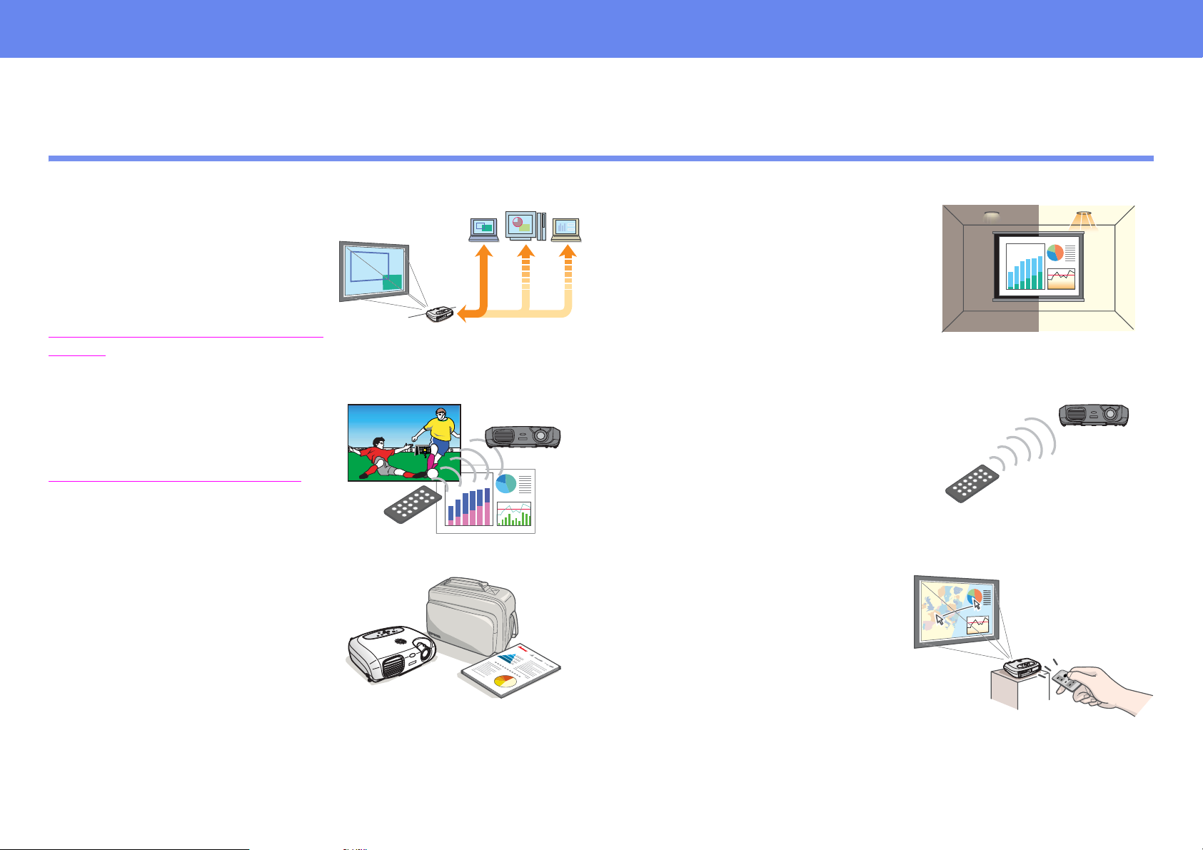
Auto setup (Computer
connections)
The projector analyzes the signal of the
computer to which it is connected and
automatically makes adjustments to
ensure optimal projection result s. See
“
Functions for Enhancing Projecti on” on
page 29.
Color mode
Image quality can be selected
according to the type of scene. See
“
Selecting a color mode” on page 29.
Compact and lightweight
The projector is compact and easy to
carry.
◗ Dimensions:
10.4 (d) × 14.6 (w) × 4.2 (h) inches
26.5 (d) × 37 (w) × 10.6 (h) cm
◗ Weight:
approximately 7 lbs (3.2 kg)
Clear, vivid, images
The projector's high resolution and high
luminance achieves a legible display.
Project sharp, detailed images, even in
bright places.
Ease of use
Various projector operations can be easily
performed using the included remote
controls, as follows:
◗ pausing projection
◗ zooming in on important areas of an
image
Unique presentation function
The mouse pointer can be moved
around on the computer screen during
projection using the included
presentation remote control.
(wireless mouse)
Page 4

Contents
4
Before Using the Pr ojector
Part Names and Functions 6
Front/Top 6
Control panel 7
Rear 8
Base 9
Remote Control 10
Installation 12
Installation method 12
Projection distance and screen size 12
Other installation methods 13
Connecting to a Computer 14
Compatible computers 14
Projecting images from a compu ter 14
Playing sound from a computer 15
Connecting to an external monitor 16
Presentation Remote Control 16
Connecting to Video Equipment 20
Projecting video image s 20
Playing sound from video equipment 21
Basic Operation
Turning on the Projector 22
Turning off the Projector 24
Adjusting the Display 25
Adjusting the projection size 25
Setting the focus 25
Adjusting the projection angle 26
Keystone 27
Selecting the Input Source 28
Advanced Operation
Functions for Enhancing Projection 29
Adjusting computer generated images 29
Selecting a color mode 29
A/V Mute 30
Freeze 30
Projecting in widescreen (changing aspect ratio) 31
E-Zoom 31
Configuration Menus 32
Menu operation 33
Function list 36
Page 5

Troubleshooting
When You Suspect a Problem 43
Power indicator 43
Warning indicator 44
When the indicators provide no help 45
Where to Get Help 53
Telephone Support Services 53
Appendix
Projector Care 54
Cleaning 54
Replacing consumables 56
5
Optional Accessories 60
Glossary 61
Cable Format 63
Supported Display Resolutions 64
Specifications 65
Important Safety Instructions 66
FCC Compliance Statement 68
Warranty 69
Index
Page 6
Part Names and Functions
Before Using the Projector
Part Names and Functions
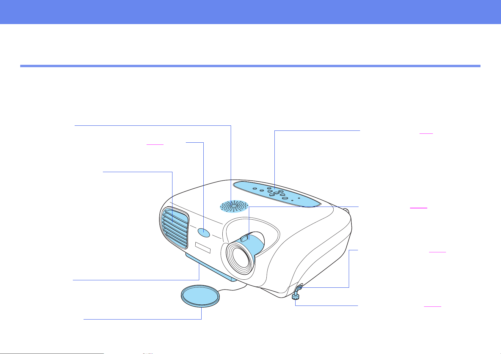
Front/Top
6
• speaker
• remote control infrared recei ver s P. 11
Receives signals from the remote control.
• ventilation outlet
• handle
Pull out this handle to use when
carrying the projector.
• lens cover
Attach when not using th e projector to pr event the
lens from becoming dirty or damaged.
• control panel s P. 7
• focus ring s P. 25
Adjusts the image focus.
• foot button (left) s P. 26
Another foot button is located on the
right side.
Press both buttons when extending
and retracting the front feet.
• front foot (left) s P. 26
Another front foot is located on the
right side.
Extend and retract to adjust the
projection angle.
Page 7
Part Names and Functions
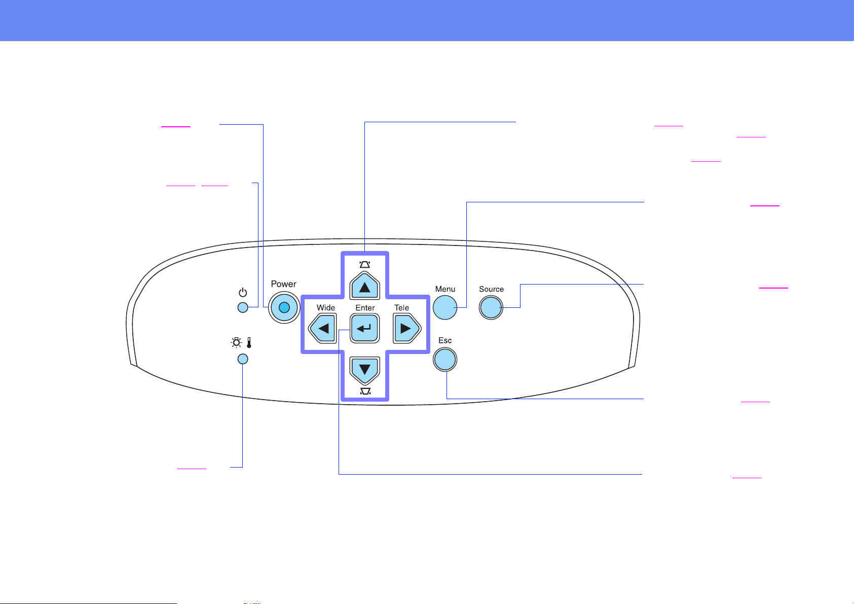
Control panel
7
• [Power] button s P. 22
Turns the projector on and off.
• Power indicator s P. 22
Flashes or lights in different colors to
indicate the operating status of the
projector.
• Warning indicator s P. 44
Flashes or lights in different colors to
alert you to problems with the projector.
, P. 43
• [u][d][l][r] buttons s P. 33
• [u][d]: keystone correction buttons s P. 27
Press to correct keystone distortion in images.
• [Wide][Tele]: zoom buttons s P. 25
• [Menu] button s P. 32
Displays or hides the
configuration menus.
• [Source] button s P. 28
Switches the input source
between the Computer/
Component Video port,
S-Video port and Video port
each time the button is pressed.
• [Esc] button s P. 35
Stops the current function.
Displays the previous screen or
menu when viewing
configuration menus.
• [e] button s P. 34
Accepts a menu item or
advances to the next screen or
menu when viewing
configuration menus.
Page 8
Part Names and Functions
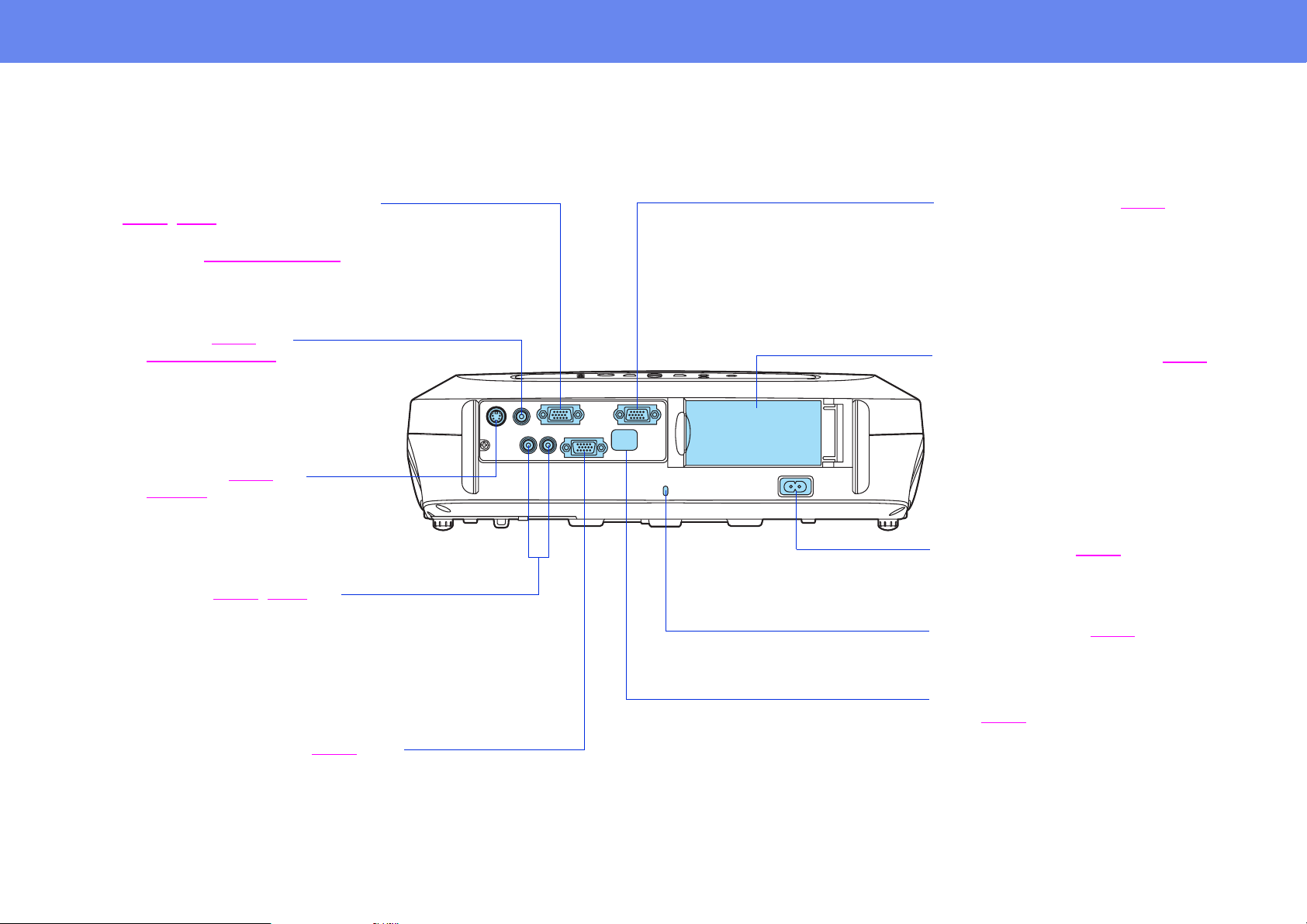
Rear
8
• Computer/Component Video port
s P. 14
Inputs analog video signals from a
computer and Component Video
signals from other video sources.
• Video port s P. 20
Inputs Composite Videog signals to
the projector.
Connect using an A/V cable.
• S-Video port s P. 20
Inputs S-Videog signals to the
projector.
Connect using an S-Video cable.
• Audio port s P. 15, P. 21
Inputs audio signals to the projector.
Connect using an A/V cable, or a stereo
RCA cable.
When using computer and video
equipment alternately, swap the cable or
use an audio switch.
• Control (RS-232C) port s P. 63
Connects the projector to a computer using an
RS-232C cable. This port is for control use and
should not be used by the customer.
, P. 20
g
• Monitor Out port s P. 16
Outputs the projected analog
computer signal to an external
monitor. This feature is not available
for video signals.
• remote control holder s P. 11
Store the remote control in here when
not in use.
• power inlet s P. 22
Connects the power cable.
• security lock s P. 62
• remote control infrared receiver
s P. 11
Receives signals from the remote
control.
Page 9

Part Names and Functions
Base
9
• ceiling mount holes (3 points)
Install the optional ceiling mount
here when suspending the projector
from the ceiling.
• rubber foot
• lamp cover s P. 57
Open this cover when replacing the
lamp inside the projector.
• handle
Pull out this handle to use when
carrying the projector.
• air filter (air intake vent) s
P. 55, P. 59
Prevents dust and other foreign
particles from being drawn into
the projector. When replacing
the lamp, replace the air filter
also.
Page 10
Remote Control
Remote Control
10
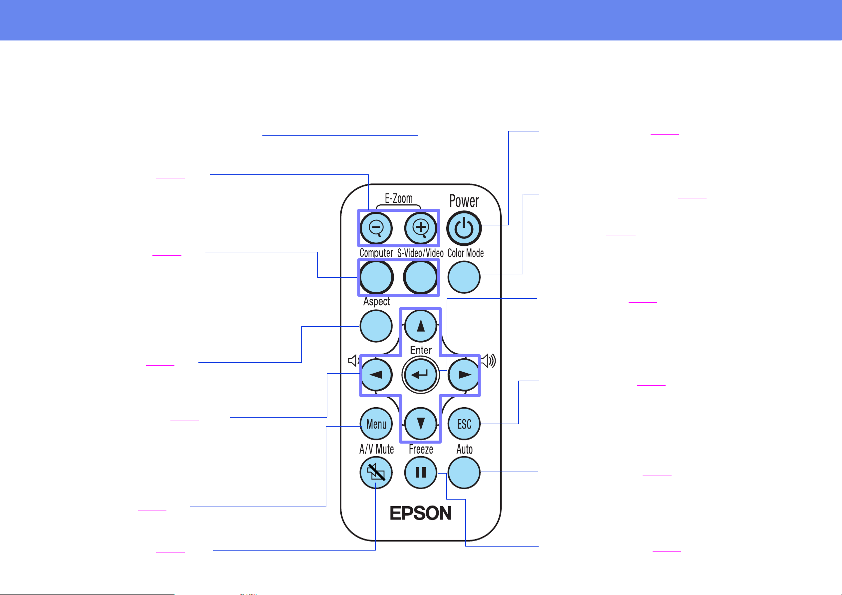
• remote control infrared transmitter
Transmits remote control signals.
• [E-Zoom] buttons s P. 31
z : Enlarges part of the image without changing the size
of the projection area.
x : Reduces the part of the image that has been
enlarged using the [z] button.
• [Source] buttons s P. 28
[Computer]: Switches to the signal source being input
to the Computer/Component Video port.
[S-Video/Video]: Switches between the signal source
being input to the S-Video port and the Video port.
• [Aspect] button s P. 31
Changes the aspect ratio of images from 4:3 to 16:9.
• [u][d][l][r] buttons s P. 33
Selects menu items and setting values.
• [Power] button s P. 22
Turns the projector on and off.
• [Color Mode] button s P. 29
Selects the color mode. The color mode changes in
the order of Dynamic, Presentation, Theatre, Living
Room and sRGB
• [e] button s P. 34
Accepts a menu item or advances to the next
screen or menu when viewing configuration menus.
• [Esc] button s P. 35
Stops the current function.
Displays the previous screen or menu when viewing
configuration menus.
g each time the button is pressed.
• [l][r]: volume buttons
Adjusts the volume.
• [Menu] button s P. 32
Displays or hides the configuration menus.
• [A/V Mute] button s P. 30
Momentarily turns off the audio and video.
• [Auto] button s P. 29
Use this button to automatically adjust computer
images to their optimum settings when automatic
setup has been set to “OFF.”
• [Freeze] button s P. 30
Keeps the current image on the screen.
Page 11
Remote Control
11
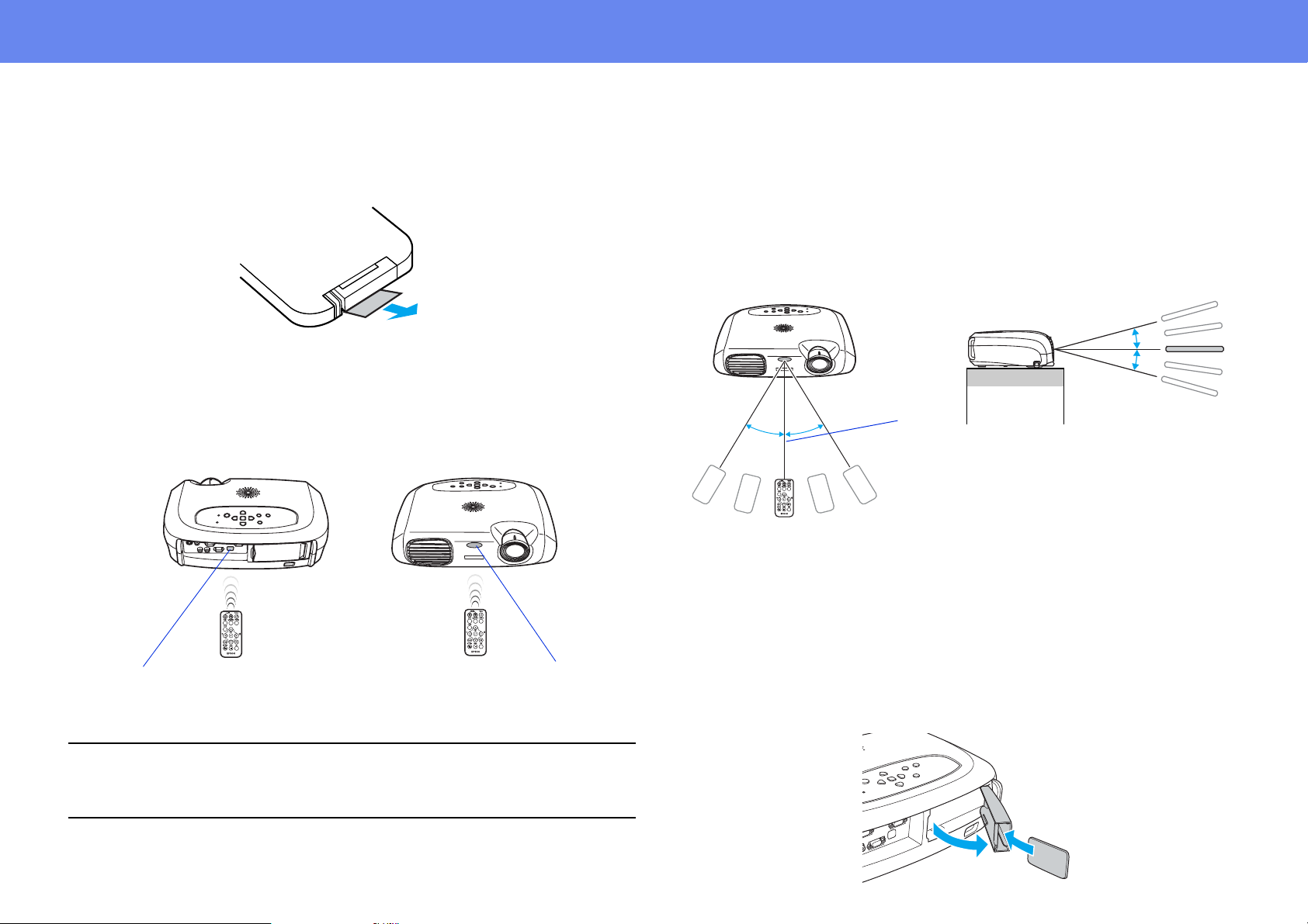
Before using the Remote Control
Remove the insulating tape.
Using the Remote Control
Operate the remote control by aiming it at the remote cont rol infr ared receiver
on the projector.
Operating range
Operable distance: Max. approximately 20 feet (6 m)
(May be shorter depending on conditions.)
Operable angle: approximately 30° horizontally, 15° vertically
* The remote control infra red receiver on the back of the proj ector c an also be
used under the same conditions.
15°
15°
Max
20 feet
30°
30°
(6 m)
Storage
remote control
infrared receiver
If direct su nlight or fluorescent lighting hits the remote control infrared
receiver, you may not be able to use the remote control.
p
remote control
infrared receiver
When not using the remote control, pl ease store i t in the r emote control holder
on the projector.
1 Open the remote control holder.
2 Place the remote control in the remote control holder.
3 Close the remote control holder until it clicks into place.
Page 12
Installation
12
Installation
Be sure to read the Important Safety Instructions before installati on.
c
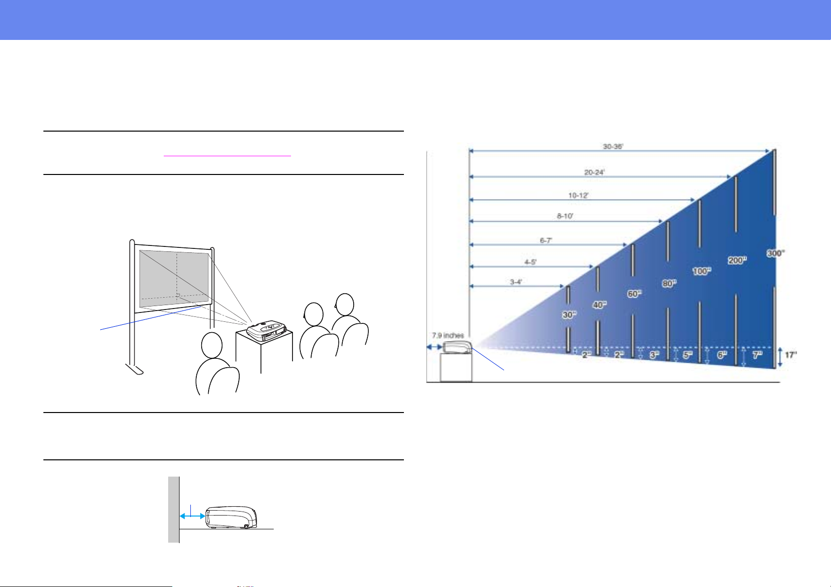
Installation method
Set up the projector so that it is at right angles to a screen.
Projection distance:
3-34 feet
(89-1050 cm)
Projection distance and screen size
Distance from projector to screen
90°
Center of
lens
screen size
Distance from center of lens
to bottom edge of screen
When setting up the projector against a wall, leave a space of at least
7.9 inches (20 cm) between the projector and the wall.
p
7.9 inches (2 0 cm) or more
Page 13
Installation
13
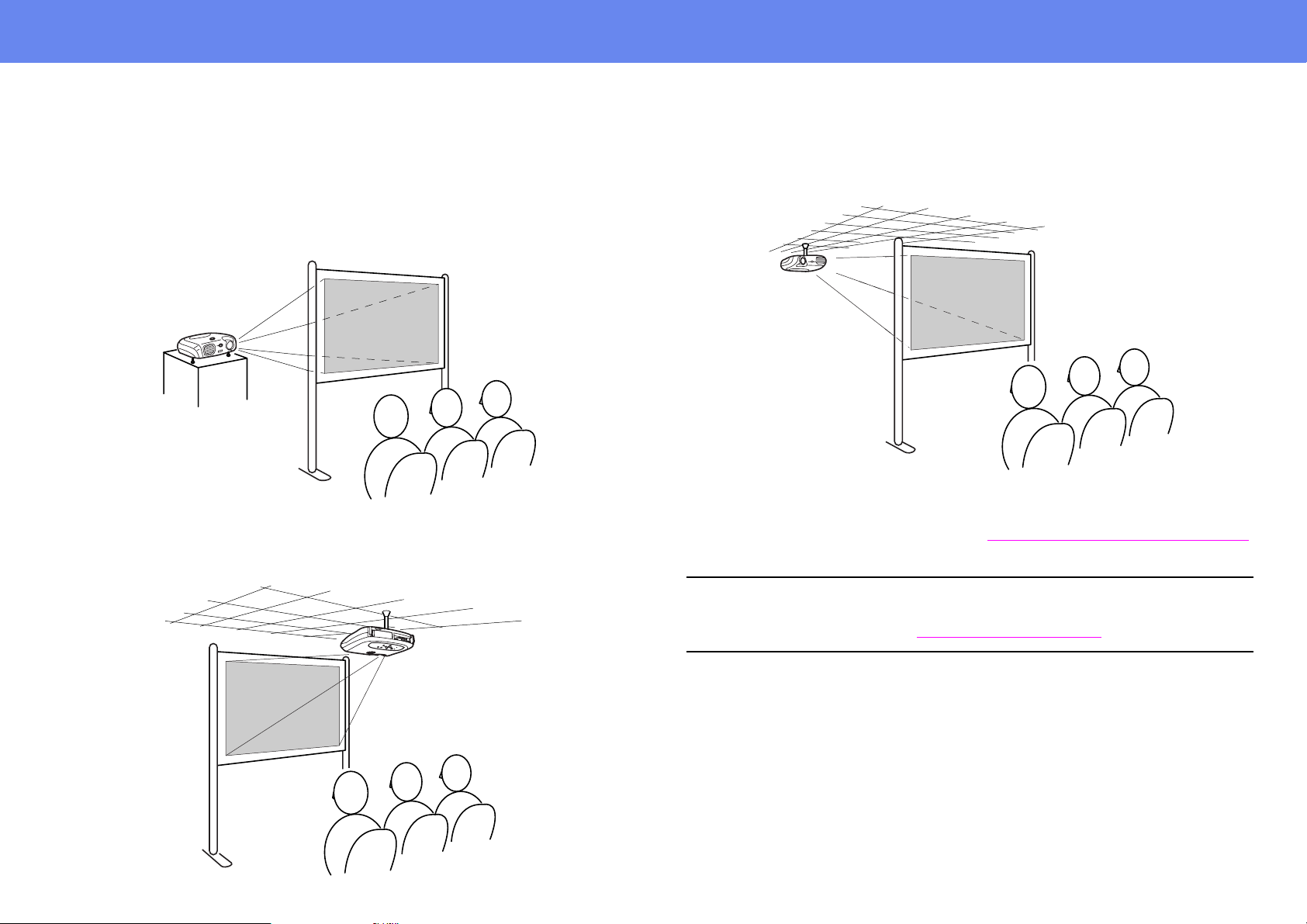
Other installation methods
Rear projection
(Using a translucent screen)
Ceiling projection
Ceiling/Rear projection
(Using a translucent screen)
The optional ceiling mount is required when ins talling the projector from a
ceiling. Please contact your dealer if you wish to use this method, as special
equipment is required for installation. See “
Optional Accessories” on page 60.
When using rear projection, or projecting from a ceiling, select the
→
appropriate mode in the “Setting”
p
configuration menu. See “
Setting menu” on page 39.
“Screen” → “Projection”
Page 14
Connecting to a Computer
14
Connecting to a Computer
When connecting, be sure to:
• Turn off the power for both the projector and the computer.
c
Compatible computers
Condition 1: Check that the computer has an image output port, such as an
RGB port, monitor port or CRT port.
Some computers with a built-in monitor and some notebook computers may
not be compatible. Please refer to your computer manual for furt her details.
Condition 2: The display frequency and resolution of the computer must
correspond to that of the projector. See “
page 64.
Damage may result if yo u try to make a connection when the power is
switched on.
• Check the connector types.
Damage may result if you attempt to insert a conne ctor into the
incorrect port.
Supported Display Resolutions” on
Setup
Press and hold the [Fn] key, followed by the appropriate function number key
that lets you display on an external monitor. Refer to your computer’s
documentation for further details.
◗ It may take a few moments until the computer image is projected.
◗ In Windows, a dialog box may appear to alert you that new display
hardware has been found. Follow the on-screen instru ctions to proceed.
If you have any problems, check the troubleshooting chapter for
possible solutions. See “
◗ Depending on the PC, the monitor may go blank when using the
external video output on the computer.
Troubleshooting” on page 43.
Projecting images from a computer
Different cables are used depending on whether the monitor port of your
computer is a Mini D-Sub 15Pin, 5BNC
When using a Mini D-Sub 15 pin connector
g or 13w3 port.
You may need to purchase a separate adapter depending on the shape of
the computer’s port. Refer to the documentation provided with the
p
computer for further details.
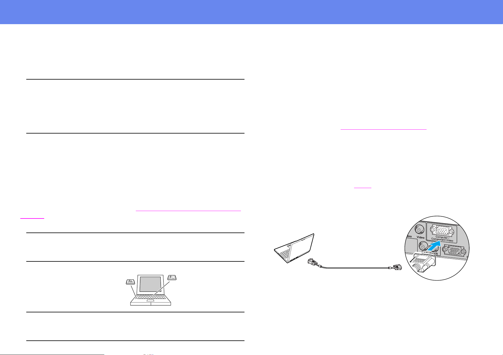
Notebook connection
When using a notebook or a PC with a built-in monitor, select external
video output on the computer.
p
To monitor port
Computer cable
(accessory)
To Computer /
Component Video port
Page 15
Connecting to a Computer
15
When using a 5BNC port
To monitor port
VGA-HD15/BNC PC
cable (optional)
When using a 13w3 port
To Computer /
Component Video port
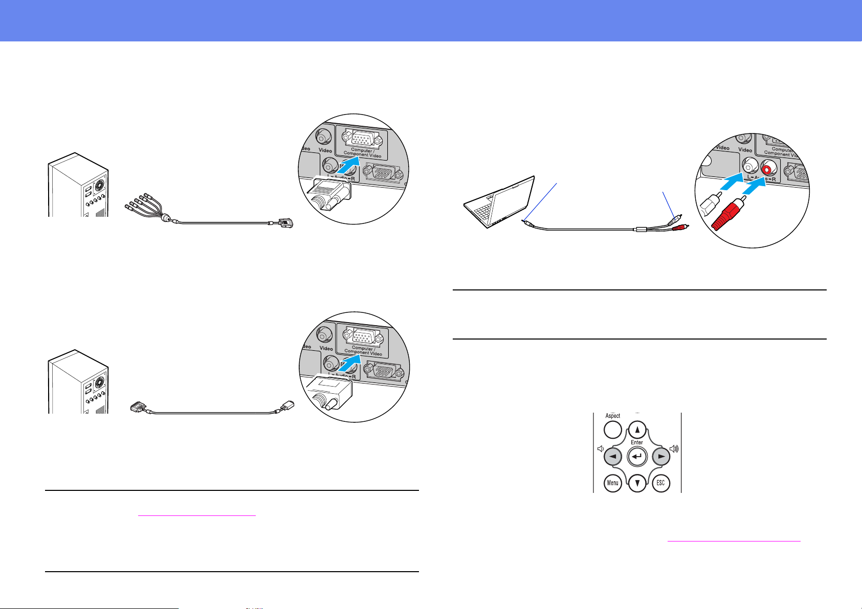
Playing sound fr om a computer
You can play sound from a computer through the projector’s built-in speaker.
stereo mini
jack
To audio out port
When using computer and video equi pment alt ernat ely, swap the cable or
use an audio switch.
p
stereo mini jack - 2RCA cable
(commercially available)
Volume adjustment
Press [l] or [r] on the remote control.
RCA jack
To Audio port
To monitor port
• Select “Computer” in the “Image” → “Input signal” configuration
p
menu. See “
• Do not bind the power cable and computer cables together. Interference
or operational problems may result.
• A particular type of cable may be re quired for some workst ations. Please
check with the maker of your workstation.
13w3 cable
(commerically available)
Image menu” on page 36.
To Computer/
Component Video port
You can also adjust the volume from the configuration menu.
([Menu] button → “Setting” → “Volume”) See “
Setting menu” on page 39.
Page 16
Connecting to a Computer
16
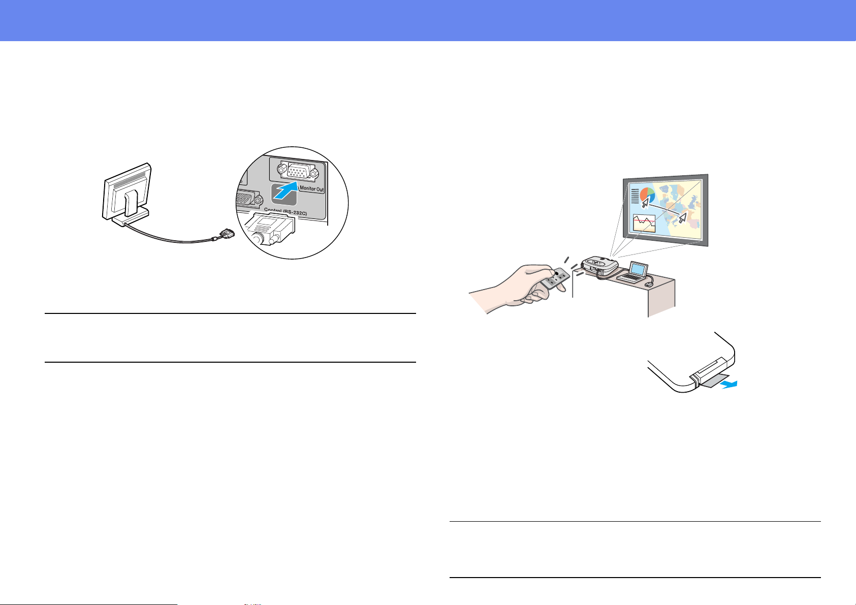
Connecting to an external monitor
The image being input into the projector can be displayed on a computer
monitor.
monitor cable
• Video images cannot be output to an external monitor.
• Setting gauges (for keystone correction, etc.) and configuration menus
p
will not be displayed on an external monitor.
To Monitor Out port
Presentation Remote Control
You can use the presentation remote control as a wireless mouse to control
the mouse pointer on the computer screen.The presentation remote contains
all the functions necessary for giving a presentation. Functions include: Page
Up/Page Down, Left/Right mouse click, A/V mute, freez e, and mouse pointer.
Before using the presentation
remote control, remove the
insulation tape.
Compatible computers
Windows: Windows 98/2000/Me/XP
(Only compatible with the full versions of Windows. Upgraded
versions cannot be used.)
Macintosh
p
: Mac OS 9.1 or later/OS X 10.1 or later
• The presentation remote receiver can only be conn ected to computers
with a standard USB interface.
• Some computer settings may have to be changed in order for the mouse
function to be used. Refer to your comput er’s do cumentat ion f or det ails .
Page 17
Connecting to a Computer
17
Installing the driver for Windows
Screen contents will differ according t o the versi on of Windows you are using.
This explanation uses screenshots taken fr om Windows 98.
Driver installation is not required for the Macintosh.
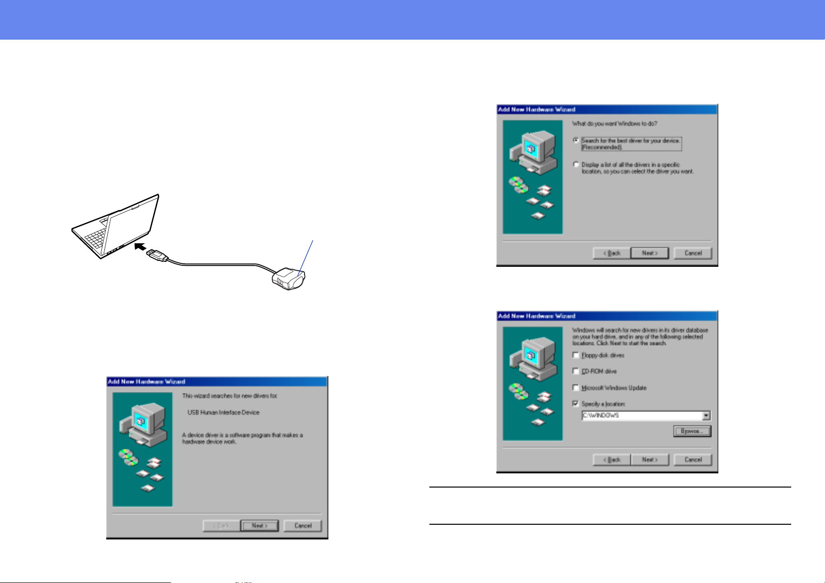
1 Connect the accessory Presentation Remot e Receiver to t he USB
port of the computer.
Infrared receiver
To USB port
The “Add New Hardware” wizard is displayed.
Under normal circumstances, maintain the defaul t settings and click
“Next” to proceed.
2 Click “Next.”
Presentation Remote
Receiver (accessory)
3 Keeping the defaults, click “Next.”
4 Click the check box next to “Specify a location.” Type
“C:\WINDOWS” and click “Next.”
• You may need to enter a different location to search for the OS files that
p
you are using.
• Click on “Browse” if you want to change the default search location.
Page 18
Connecting to a Computer
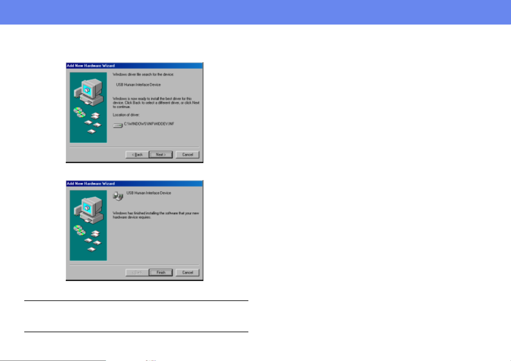
5 Click on “Next” to confirm the message which is displayed.
6 Click on “Finish.”
18
The installation of the driver is complete.
The driver installation screen is displayed a second time.
(The presentation remote control driver has two parts; the mouse driver
and the keyb oard driv er . ) Follo w the on-scr een instru ctions to co mplete the
p
installation.
Page 19
Connecting to a Computer
Part Names and Functions
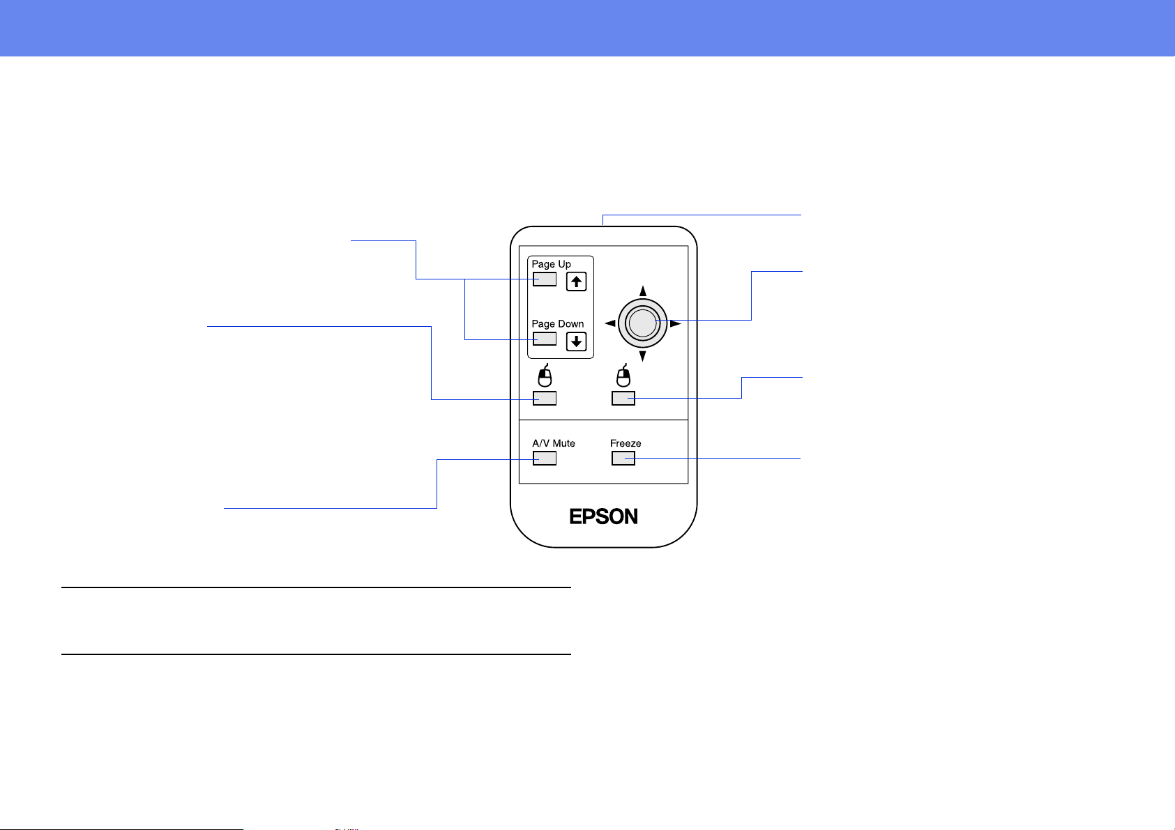
Operate the presentation remote control by aiming it at the presentation remote receiver.
When using the Freeze or A/V Mute functions, aim the present ation remote control towards the remote control in frared receiver of the projector.
• remote control infrared transmitter
• [Page Up] / [Page Down] buttons
Press these buttons to scroll back and forth
through pages when projecting a
presentation.
• [L Click] button
Acts as a mouse left-click.
Transmits remote control signals.
• joystick
To move the mouse pointer, move the
joystick in any of the following
directions: up, down, left, ri ght, diagonally.
19
• Double click:
Push the [L Click] button twice.
• Drag and drop:
To drag, press and hold the [L Click] button and move
the cursor with the joystick.
The item will be dropped when [L Click] is released.
• [A/V Mute] button
Momentarily turns off the audio and video.
If the mouse button settings have been reversed on the compute r, the
operatio n of the remote control buttons will also be reversed.
p
• [R Click] button
Acts as a mouse right-click.
• [Freeze] button
Keeps the current computer or
video image on the screen.
Page 20
Connecting to Video Equipment
20
Operating range
Operable distance: Maximum approximately 20 feet (6 m)
(may be shorter depending on conditions)
Operable angle: Approximately 30° horizontally, 15° vertically
30°
30°
Max 20 ft (6 m)
15°
15°
Connecting to Video Equipment
When connecting, be sure to:
• Turn off the power for both the projector and the video equipment.
c
Damage may result if yo u try to make a connection when the power is
switched on.
• Check the connector types.
Damage may result if you attempt to insert a conne ctor into the
incorrect port.
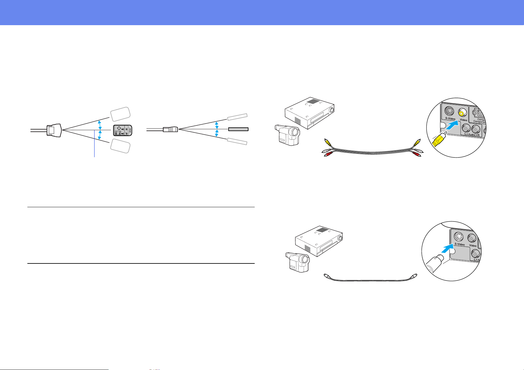
Projecting vide o images
For Composite Video (DVD, VHS, Video games)
To video
out port
To audio out
port
AV cable (yellow)
(commercially
available)
For S-Video (DVD, VHS, Video games)
To S-Video out
port
To Video
port
To Audio
port
To S-Video
port
S-Video cable
(commercially
available)
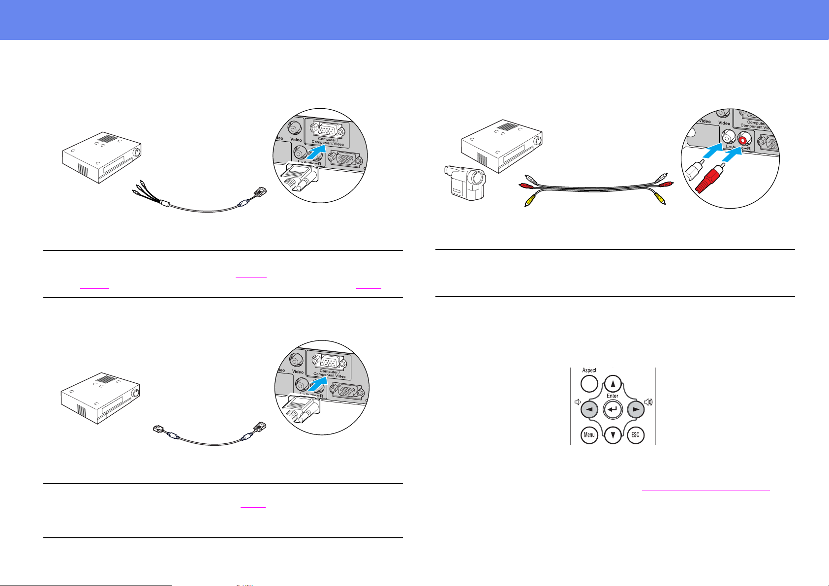
Page 21
Connecting to Video Equipment
21
For Component Video (DVD, Video games)
Component video
cable (optional)
To component
video out port
After projection starts, change the “Input Signal” setting in the “Image”
menu to either “Component Video (YCbCr
p
(YPbPr
g)” to match the signals from the video equipment. s P. 36
To Computer/
Component Video port
g)” or “C omponent Video
For RGB Video
Playing sound from video equipment
AV cable (red/white)
(commercially available)
When using computer and video equi pment alt ernat ely, swap the cable or
use an audio switch.
p
Volume adjustment
Press [l] or [r] on the remote control.
To Audio portTo audio out port
Computer cable
(accessory)
To RGB out port
• After projection starts, change the “Input Signal” setting in the
p
“Image” menu to “Computer.” s P. 36
• For an RGB connection, a commercially available adapter or converter
cable may be required.
To Computer/
Component Video port
You can also adjust the volume with the configuration menu.
([Menu] button → “Setting” → “Volume”) See “
Setting menu” on page 39.
Page 22
Turning on the Projector
Basic Operation
22
Turning on the Projector
Turn of f the po w er of the pr ojector and the equipment you are conn ecting
c
to.
1 Connect the computer/video.
Connecting to a Computer” on page 14, “Connecting to Video
See “
Equipment” on page 20.
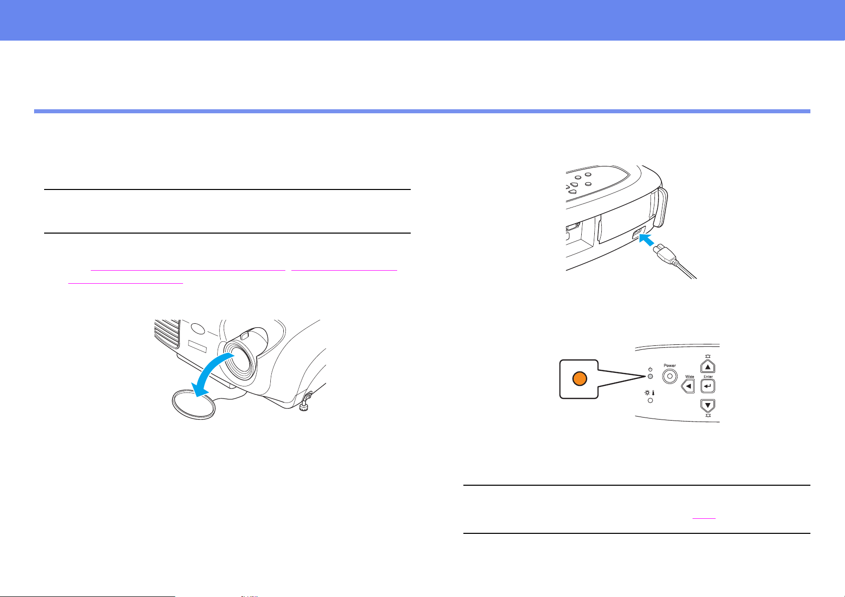
2 Remove the lens cover.
3 Attach the power cable to the projector.
4 Insert the power plug into a wall socket.
The power indicator lights orange.
5 Turn on the power of the computer/video.
If connected to a video source, start playback.
When using a notebook or a PC with a built-in monitor, select
external video output on the computer. s P.14
p
Page 23

Turning on the Projector
6 Press the [Power] button.
The projector beeps and the power supply indicator begins to blink
green.
7 Wait until the power indicator lights green.
It takes about 35 seconds.
23
Page 24

Turning off the Projector
24
Turning off the Projector
1 Turn off the power to the computer/video equipment.
2 Press the [Power] button.
A confirmation screen is displayed.
4 Wait until the power indicator lights orange.
Cool-down
5 Unplug the projector from the outlet.
c
6 Unplug the power cable at the projector.
7 Replace the lens cover.
g takes place. It takes about 20 seconds.
Do not remove the plug while the power indicator is blinking, or this
may damage the projector.
Turn the projector off when not in use. Continuous 24-hour-a-day
use may reduce its overall life .
The confirmation screen disappears if anything other than the
[Power] button is pressed, or if nothing is pressed for 7 seconds.
p
3 Press the [Power] button again.
The power indicator begins to blink.
Page 25

Adjusting the Display
25
Adjusting the Display
Adjusting the projection size
The size of the projected image is basically determined by the distance from
the projector to the screen. See “
page 12.
1 Press the [Wide] or [Tele] buttons on the control panel to adjust
the projection size.
[Wide]: increase the size
[Tele]: reduces the size
The image can be enlarged in this way to 1.2 times the normal size.
If you would like to enlarge the image further, move the projec tor
further away from the screen.
Projection distance and screen size” on
Setting the focus
Turn the focus ring to adjust the image focus.
• If the surface of the lens is dirty, or misted over as a result of
p
condensation, it may not be possible to adjust t h e focus correctly. If
this happens, clean or de-mist the lens. See “
page 54.
• If the projector is positioned out side the normal proje cting range of
2.9-36.4 feet (87-1109 cm), it may not be possible to obtain the
correct focus. If you have trouble obtaining the correct focus, check
the projection distance.
Cleaning the lens” on
• Th e default setting is wide.
• The E-Zoom function lets you enlarge parts of the image.
p
See “
E-Zoom” on page 31.
Page 26

Adjusting the Display
26
Adjusting the projection angle
1 Set up the projector so that it is at right angles to the screen.
Seen from the side
Center of
lens
Seen from above
2 Raise the front of the projector while pressing the buttons on
both sides.
3 Extend the front feet and release the buttons when the projector
is adjusted to the desired height.
• The height can be adjusted by turning the base of the front feet on
either side.
p
If it is not possible to set up the projector so that it is at right angles to
the screen, it can be set up at a slight vertical angle instead. (Max
10°)
• Press the front buttons on both sides and slowly lower the projector
down to return to its normal position.
Page 27

Adjusting the Display
27
Keystone
When the projector is not set at right angles to t he screen , t he displ ay dis torts
in the shape of a trapezoid. This distortion can be corr ected.
You can correct only vertical distortion with this function. Horizontal
distortion cannot be corrected.
p
Press the [u] or [d] buttons.
Images can be corrected without distortion when the projector is tilted to a
maximum of ±15°.
Approx. 15° above Approx. 15° below
15°
15°
• Screen size chan ges when keystone correction is performed.
• If the images become uneven in appearance after keystone
p
correction is performed, decrease the sharpness setting. ([Menu]
button
“
→
“Image” → “Picture Quality” → “Sharpness”) See
Image menu ” on page 36.
Page 28

Selecting the Input Source
28
Selecting the Input Sourc e
When a device is connected, projection commences automat ically without
having to select the input source, however when connected to two or more
devices, you need to switch between the input sources.
Projector
Computer/
Component video
S-Video
Video
The input source changes each time [Source] is pressed.
Remote control
Computer
Component Video
Component Video
The input source switches between Computer and Component video
whenever the [Computer] button is pressed, as shown above.
The items selected using the “Input s ignal” command in the “ Image” menu are
displayed. See “
Image menu” on page 36.
S-Video
Video
The input source switches between S-Video and Video whenever the
[S-Video/Video] button is pressed, as shown above.
If two or mo re sources are connected, be sure to swap the audio cables
between the connected equipment, when necessary.
p
Page 29
Functions for Enhancing Projection
Advanced Operation
29
Functions for Enhancing Projection
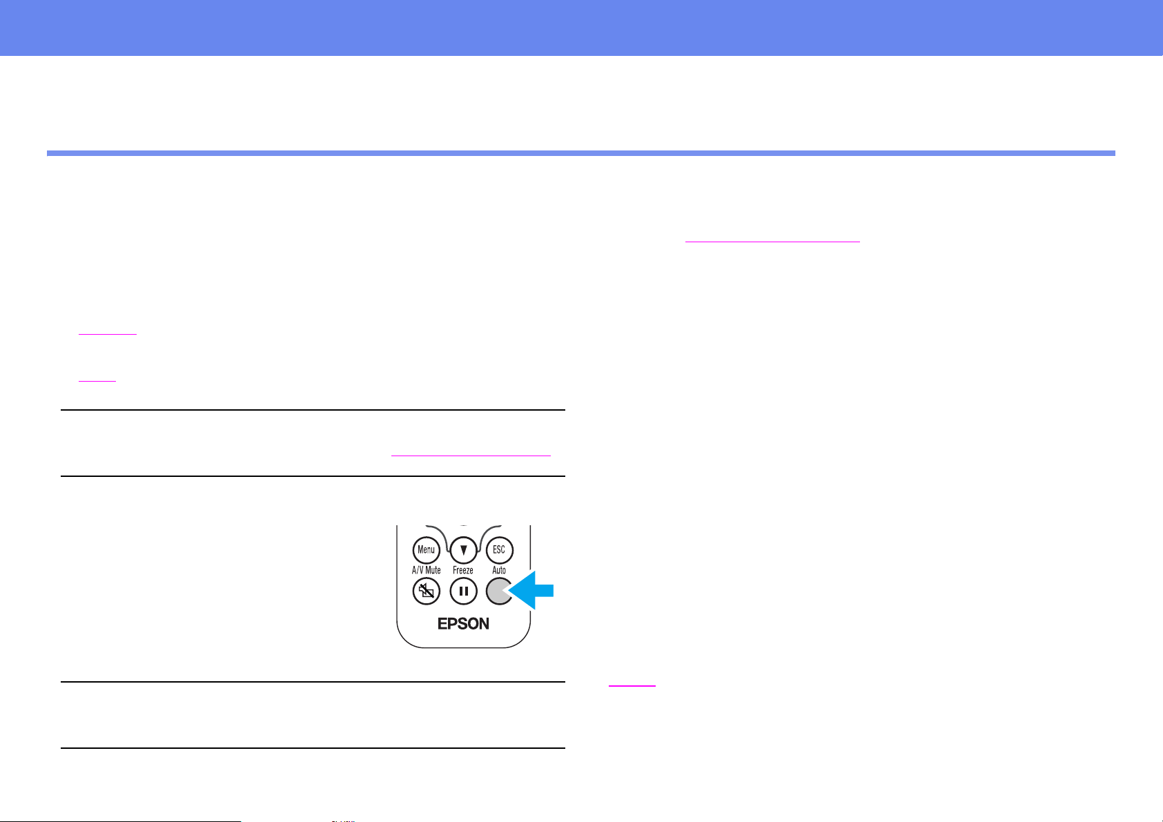
Adjusting computer generated images
The computer signal is analyzed and the following setti ngs are adjusted to
ensure the optimum image quality.
◗ Tracking
◗ Position
◗ Sync.
p
When Auto setup is set to off, press the [Auto]
button on the remote control to perform auto
setup.
g
g
You can set Auto setup to off in the “Image” → “Auto Setup”
configuration menu. (The default is ON) See “Image menu” on page 36.
Adjust the Tracking and Sync settings manually if Auto setup cannot be
performed. ([Menu] button → “Image” → “Picture Quality” → “Tracking,”
“Sync.”) See “
Image menu” on page 36.
Selecting a color mode
There are five present color modes available for use. Make a selection
appropriate to the conditions in which you are proje cting.
• Dynamic
Images are modulated and made crisper to emphasize brightness.
• Presentation
Brightness is emphasized. For presentations in bright rooms.
• Theatre
Best for watching movies in their natural tones.
• Living Room
If you press the [Auto] button during E-Zoom or Freeze operation, or
when a configuration menu is being displayed, the display will be halted
p
and auto setup will take place.
Brightness is emphasized. Ideal for playing video games in bright
rooms.
• sRGBg
Conforms to the sRGB color s tandard. If the connected source has an
sRGB mode, set both the projector and the connected source to
sRGB.
Page 30

Functions for Enhancing Projection
30
The color mode changes each time you press the
[Color Mode] button on the remote control.
Dynamic → Presentation → Theatre → Living
Room → sRGB
Default Value
◗ Computer input: Presentation
◗ Other input: Dynamic
You can set the color mode in the “Image” → “Color Mode”
configuration menu.
p
Image menu” on page 36.
See “
A/V Mute
Temporarily stops the image and sound.
◗ Press the [A/V Mute] button on the remote
control. The sound and image disappear.
◗ Projection is resumed when you press the
[A/V Mute] button again or press the [Esc]
button.
Freeze
Pauses the projected images.
◗ Press the [Freeze] button on the remote
control. The projected image freezes.
◗ To cancel, press the [Freeze] button again,
or press the [Esc] button.
• During Freeze, moving images will continue to be played back by the
p
source, so it will not be possible to return to the point where Freeze was
activated.
• Pressing the [Freeze] button also clears configuration menus.
• The screen color during A/V Mute can be set to black or blue. The
→
p
default setting is blue. ([Menu] button
“Background Color”) See “
• When activated while projecting moving images, the sound and image
will continue to be played back by the sou rce, so it wi ll not be pos sible to
return to the point where A/V Mute was activated.
Setting menu” on page 39 .
“Setting” → “Display” →
Page 31

Functions for Enhancing Projection
31
Projecting in widescreen (changing aspect ratio)
This function changes the Aspect ratiog of images from 4:3 to 16:9 when
component video images (YCbCr and YPbPr) or video images (S-Video or
composite video) are being projected. Images which have been recorded in
digital video or onto DVDs can be viewed in 16:9 wide-screen format.
Press the [Aspect] button on the remote control
to change the screen size as follows:
E-Zoom
The image is enlarged or reduced.
1 Press the [E-Zoomz] button on the
remote control.
A target scope is displayed on the screen.
2 Press the [u][d][l][r] buttons to move
the target scope to the center of the part you wish to enlarge/
reduce.
target sco pe
3 Push [E-Zoomz] to enlarge the image. Push
[E-Zoomx] to reduce the enlarged image.
When images in Squeeze
modeg are projected at 4:3
When images in Squeeze
mode are projected at 16:9
enlargement ratio
• [E-Zoomz]: Enlarges part of the image without changing the size
of the projection area.
• [E-Zoomx]: Reduces the part o f the image that has been enlarged
using the [z] button.
• You can scroll with the [u][d][l][r] buttons.
• Press [Esc] to cancel.
Page 32

Configuration Menus
Configuration Menus
Various adjustments and settings can be made within the configuration menus. Depending on your video source, some setting s may not be available.
Image rrColor Mode Image rrColor Mode
(Computer Images) (Video Images)
r Picture Quality rrBrightness r Picture Quality rrBrigtness
r Contrast r Contrast
r Sharpness r Saturation
r Tracking r Tint
r Sync. r Color Temperature
r Color Temperature r Sharpness
r Auto Setup r Input Signal
r Input Signal
r Reset r Reset
Setting rrScreen rrKeystone
r Position
r Projection
(Component video only)
32
r Display rrMessage
r Background Color
r Startup Screen
r Video Signal
r Volume
r Sleep Mode
r Language
r Reset
Info r Lamp Hours Info r Lamp Hours
(Computer Images) Source (Video Images) Source
Input Signal Video Signal
Resolution
Refresh Rate
Sync Info
Reset rrLamp-Hours Reset
r All Reset
Page 33

Configuration Menus
33
Menu operation
1 Press the [Menu] button
The top configuration menu is displayed.
Top Menu
2 Press the [u] or [d] buttons to select the Top Menu item.
Sub Menu 1
Page 34

Configuration Menus
34
3 Press the [e] button.
Sub Menu 1 is displayed.
6 Settings can be changed in the following ways:
(a) Press the [l] or [r] buttons to change the setting values.
(b) Press the [u] or [d] buttons to select the menu item.
Then press the [e] button.
4 Press the [u] or [d] buttons to select the Sub Menu 1 items, then
press the [e] button.
5 For Sub Menu 2, press the [u] or [d] buttons in the same way,
then press the [e] button.
(Green): Item cu r re n tly set.
(Orange): Item currently selected.
Press the [e] button to confirm the selection.
The mark is displaye d after i tems which perfor m a sett ing or lead
to a sub menu.
p
Page 35

Configuration Menus
(c) Press the [l] or [r] buttons to select the value.
Then, press the [e] button.
(d) Press the [u] [d] [l] [r] buttons to move the image display
position.
35
7 Set other items in the same way.
Press the [Esc] button to ret urn to the prev ious i tem or menu, or select
“Return.”
8 Press the [Menu] button to finish.
Page 36

Configuration Menus
Function list
Image menu
• When no signal is being input, only the settings for “Auto Setup” and “Input Signal” can be adjusted.
• The functions in the “Image” Menu will be dif ferent according to the type of signal which is being input.
36
Computer images Video images
“Input Signal” only appears on menu screens when component video images
are being projected.
Page 37

Configuration Menus
Sub menu Function
Color Mode Corrects the vividness of the image color. The settings can be saved separately for each type of source
(computer or video).
Select from 5 different quality settings dependi ng on the type of scene.
◗ Dynamic:
Images are modulated and made crisper to emphasize brightness.
◗ Presentation:
Brightness is emphasized. For presentations i n bright rooms.
◗ Theatre:
Best for watching movies in their natural tones.
◗ Living Room:
Brightness is emphasized. Ideal for playing video games in bright rooms.
37
Picture
Quality
◗ sRGB
g:
Conforms to the sRGB color standard. If the connected source has an sRGB mode, set both the
projector and connected source to sRGB.
Brightness Adjusts the brightness of the image.
Contrast
g Adjusts the contrast of the image.
Sharpness Adjusts the sharpness of the image.
Tracking
g
Adjusts the image when vertical stripes appear in the image.
(Computer images
only)
Page 38

Configuration Menus
Sub menu Function
38
Picture
Quality
Sync.g
(Computer images
only)
Color Temperature
Saturation
(Video images only)
Tint
(Video images only)
Auto Setup
(Computer images only)
Input Signal
(Computer/component
video images only)
Adjusts the image when flickering, fuzziness or interference occur in the image.
Flickering and fuzziness may also occur when the bri ghtness, contrast, sharpness or keystone correction
settings are adjusted.
Best results can be obtained by adjusting the tracking before the sync.
g Adjusts bright colors from a reddish tinge to a bluish tinge.
Lower color temperature settings produce redder colors and softer color tones.
Higher color temperature settings pr oduce bluer colors and sharper color tones.
Press the [e] button and make a setting from the color a djustment menu which is displayed.
Adjusts the color depth
(Adjustment is only possible when Component Vide o
g or NTSC signals are being input)
Adjusts the tint of the image.
ON: When the input source is switched to a computer sign al, the proj ector aut omatical ly adj usts th e image
to its optimal state.
OFF: Auto Setup is disabled.
Select the type of image signal connected to the Computer/Component Video port .
Computer: computer images
Component Video (YCbCr): DVD images
Component Video (YPbPr): HDTV images
Reset Resets all the adjustment values within the “ Image” menu ( except for “I nput Signal” ) to their default set tings.
Press the [e] button and select “Yes” on the confirmation screen which is displayed.
Select “All Reset” to restore all menu settings, such as image and sound, to their default settings. See
Reset menu” on page 42.
“
Page 39

Configuration Menus
Setting menu
39
Sub menu Function
Screen Keystone Corrects vertical ke ystone distortion in the image.
The projected image changes when keystone correction is carried out.
If the images become uneven in appearance after keystone correction has been carried out, decrease the
sharpness setting.
Position Moves the image display position vertically and horizontally.
Press the [e] button and adjust the display area on the Position adjustment screen which is displayed.
Projection Front
Image is displayed, as is. No vertical/horizontal reversal performed.
Front/Ceiling
The image is displayed vertically reversed.
Rear
The image is displayed horizontally reversed.
Rear/Ceiling
The image is displayed vertically and horizontally reversed.
Page 40

Configuration Menus
Sub menu Function
Display Message When set to “off,” messages such as “No signal,” and the name of the selected input source or color mode
will no longer be displayed. Warning messages such as “Replace the lamp” will continue to be displayed.
Background Color Sets the background color to black or blue.
Startup Screen Sets whether or not the EPSON logo will be displayed during projector startup.
Video Signal Selects the format of the video signal being input.
(Changes in signal format will only be noticeable when the input source is Video/S-Video.)
Volume Adjusts the volume setting
Sleep Mode Sets the energy sa ving option for when no signal is being input.
• When a Sleep Mode interval has been set, the projector will enter Sleep Mode when no operation has
been carried out f or the s et ti me (5, 10 a nd 30 mi n utes). Project ion wi ll shu t down and the projector enters
a standby state after cooling down. (The power indicator lights orange).
• Projection starts again when the [Power] button is pressed on the projector's contol panel or the remote
control.
40
Language Selects the language in which on-screen messages are displayed.
• Press the [e] button and select the desired language from the list which is displayed.
Reset Resets all the adjustment values wit h in the “Setting” menu (except for “Language”) to their default settings.
• Press the [e] button and select “Yes” on the confirmation screen which is displayed.
Page 41

Configuration Menus
Info menu
41
Computer images Video images
Sub menu Function
Lamp Hours Displays the cumulative lamp operating time.
When the accumulated usage time of the lamp reaches about 1900 hours, a warning will be displayed in red.
Source Displays the input source being projected.
Input Signal (Computer images only) Displays the input signal settings.
Video Signal (Video images only) Displays the Video signal format.
Resolution
(Computer images only)
Refresh Rate
(Computer images only)
Sync Info
(Computer images only)
g
Displays the input resolution.
(Does not appear when the input source is composite video or S-Vide o.)
Displays the refr esh rate
(Does not appear when the input source is composite video or S-Vide o.)
Displays pict ure signal information.
In the event that you are having problems with your projector and need to contact EPSON, please quote the
information displayed on this screen.
Page 42

Configuration Menus
Reset menu
42
Sub menu Function
Lamp-Hours Reset Resets the lamp operating time. When this command is selected, the cumulativ e lamp oper ating time is reset to the d ef ault
value.
All Reset Resets all items in the configuration menus to their default setti ngs.
• Press the [e] button and select “Yes” on the confirmation screen which is displayed.
• Select “Reset” in an individual menu to reset only the settings for the items in t hat sub menu.
• “Input Signal,” “Language” and “Lamp Hours” settings will not be reset.
Page 43

When You Suspect a Problem
Troubleshooting
When You Suspect a Problem
First, check the indicators on the projector. There are two indicators on the projector unit which noti fy you of projector conditions.
Power indicator
Warning indicator
43
Power indicator
lit flashing • If the indicator is not lit, the power supply is not on.
Condition Cause/Remedy s
Orange Standby state
The power cable should only be disconnected when the projector is in this state.
Press the [Power] button to start projection.
Orange Cool-down in progress
• Please wait. The cool-down period lasts about 20 seconds.
• You cannot operate the [Power] button during the cool-down period. Press the power button again after cool -down has
finished.
Green Projection in progress
Green Warming-up
Please wait. Warming up takes about 35 seconds (the EPSON logo appears after approximately 6 seconds). When warming
up is complete, the indicator changes to steady green.
P.22
P.22
P.22
P.22
Page 44

When You Suspect a Problem
Warning indi c ator
lit flashing • Lit under normal operating conditions.
Condition Cause/Remedy s
Red High internal temperature (overheating)
The lamp turns off automatically and projection stops. Wait for about 5 minutes without operating the projector. After
about 5 minutes hav e passed, unplug the power cable and check the following:
• Make sure the air filter an d ventilation outlet are clear and that the projector is not positioned against a wa ll.
• If the air filter is dirty, it should be cleaned.
When the power cabl e is plugged back in, the projector will return to its previous state. Press the [Po w er] button on the
projector or on the remote control to turn it back on.
Red
(0.5 second interval)
Red
(1 second interval)
Orange High-speed cooling in progress
Lamp problem
• Disconnect the power cable from the electrical outlet. Remove the lamp and check that it is not broken. If the lamp is
not broken, re-install it. Reconnec t t he pow er ca b l e and press th e [Power] button on the projecto r or the remot e contr ol
to turn it back on.
• If the lamp is broken, please contact your dealer or see Where to Get Help
use the projector until the lamp is replaced).
• Check that the lamp and lamp cover are securely installed. If the lamp or lamp cover are not securely installed, the
lamp will not switch on.
Internal problem
Stop using the projector, disconnect the power cable from the electrical outlet and contact your dealer or see Where to
Get Help to contact EPSON.
(This is not abnormal, but, if the t emper ature rises too hi gh again, project ion will sto p auto matical ly.) Set up the projector
in a place which is well ventilated and ensure the air filter and ventilation outlet are clear. Clean the air filter.
to contact EPSON. (You will not be able to
44
P.12
P.54
P.54
P.12
P.54
• If problems with projection do occur, but the indicators do not show any abnormal conditions, please refer to the section “When the indicators
p
provide no help” on the next page.
• If a condition oc curs which is not listed in this table, p lease consult your dea ler or see Where to Get Help
• If you follow the above steps and are still unable to correct the problem, please cease using the projector, unplug the projector from the electrical
outlet and request repairs from your dealer or see Where to Get Help
to contact EPSON.
to contact EP SON.
Page 45

When You Suspect a Problem
45
When the indicato rs provide no help
• No images appear (Nothing is displayed) page 45
• No images appear (Messages are displayed 1) page 46
• No images appear (Messages are displayed 2) page 46
• Image is out of focus (unclear) page 47
• Vertical stripes appear in the image page 48
No images appear (Nothing is displayed)
• Was the power turned off and then straight back
on again?
• Has a Sleep Mode interval (5, 10 or 30 minutes)
been set?
• Has the image brightness been adjusted
correctly? ([Menu] button → “Image” → “Picture
Quality” → “Brightness”)
• Is the projected image completely black? Some images being displa yed, including some sc reen sa vers , ma y be completely
• Is A/V Mute activated? See “
• Have you pressed the [Power] button? See “
• Try resetting all of the current settings. See “
• Is an image signal being input? Check if a picture signal is being input.
• Image is distorted / Image contains interference page 48
• Only part of the image is displayed (large/small) page 49
• Image colors are poor, tinted green or tinted red/purple page 50
• Image is dark page 51
• No sound can be heard page 51
• The remote control does not work page 52
• The power does not turn off (after the [Power] button is pressed) page 52
After the pow er has been s wi tched off and the projector is in c ool-down mode , the
[Power] button will not work.
When a Sleep Mode interval has been set, the lamp cuts out after no operations
have been carried out for the set time (5, 10 or 30 minutes).
The power indicator lights orange at this time. ([Menu] button → “Setting” →
“Sleep Mode”) See “
Image menu” on page 36.
See “
black.
A/V Mute ” on page 30.
Turning on the Projector” on page 22.
Reset menu” on page 42.
Set the “Message” option to “ON” in the “Setting ” → “Displ ay” → “Message”
configuration menu, in order to view the picture signal information. See “
menu” on page 39.
Setting menu” on page 39.
Setting
Page 46

When You Suspect a Problem
No images appear (Messages are displayed 1)
46
• Check the mode which corresponds to the
frequency of the image signals being output f rom
the computer.
“Not supported”
No images appear (Messages are displayed 2)
• Has external video output been selected on the
computer?
• Is the input source properly selected? Press the [Source] button on the Control panel unti l the correct input source is
“No signal”
• Are the cables connected properly? See “
• Is the power for the connected computer or video
source switched on?
Refer to the documentation provided with your computer for details on changing
the resolution and frequency of the image signals being output from the
computer. See “
When using a notebook or a PC with a built-in monitor, select external video
output on the computer.
Notebook connection” on page 14.
See “
selected. For the remote control, press the [Computer] button or the [S-Video/
Video] button. See “
Connecting to a Computer” on page 14, "Connecting to Video Equipment"
P.20.
Turning on the Projector” on page 22.
See “
Supported Display Resolutions” on page 64.
Selecting the Input Source” on page 28.
Page 47

When You Suspect a Problem
Image is out of focus (unclear)
47
• The image is
fuzzy
• Part of the image
is out of focus
• The whole image
is out of focus
• Have the “Sync.
settings been adjusted correctly?
• Are the image signal format settings correct? • When a computer or Component Video
• Is the projector positioned at right angles to the
screen?
• Is the projector at the correct distance from the
screen?
• Are the front feet set so that the image angle is
too big for the screen?
• Is the lens dirty? See “
• Has condensation formed on the lens? If the projector is suddenly taken from a cold environment to a warm
• Has the focus been correctly adjusted? See “
• Is the lens cover still in place? See “
g,” “Trackingg” and “Position”
If the configuration menu “Image” → “Auto Setup” setting has been set to “OFF,”
press the [Auto] button on the remote control to adjust these settings. If the
images have not been correctly adjusted after pressing the [Auto] button and
using the auto setup function, adjust the settings manually in their respective
menus. ([Menu] but ton → “Image” → “Picture Quality” → “Tracking,” “Image” →
“Picture Quality” → “Sync.,” “Setting” → “Screen” → “Position”) See “
menu” on page 36, "Setting menu" P.39.
g device is connected, select the
appropriate setting for the input source you are using, i n the “Image” → “Input
Signal” configuration menu.
• When a Composite Video
appropriate setting for the video system you are using in the “Setting” →
“Video Signal” configurati on menu.
Installation method” on page 12.
See “
The optimum range f or projection is 2.9-36 .4 f eet (87-1109 cm). Set the projecto r
within this range. See “
If the image angle is too big the image will be out of focus vertically. See
Adjusting the projection angle” on page 26.
“
Cleaning the lens” on page 54.
environment, condensation may form on the surface of the lens, and this may
cause the images to appear fuzzy. Set the projector up in the room in which it is
to be used appro ximately one hour bef ore u se. I f condensation forms on the lens,
turn off the power and wait for the condensation to disappear.
Adjusting the Display” on page 25.
Turning on the Projector” on page 22.
g or S-Videog device is connected, select the
Installation method” on page 12.
Image
Page 48

When You Suspect a Problem
Vertical stripes appear in the image
• Has the “Trackingg” setting been adjusted? Set the tracking value until the vertical stripes disappear. ([Menu] button →
Image is distorted / Image contains interference
“Image” → “Picture Qualit y” → “Tracking”) See “
48
Image menu” on page 36.
• Have the “Sync.g,” “Trackingg” and “Position”
settings been adjusted correctly?
• Are the image signal format settings correct? • When a computer or Component Video
• Has the correct resolution been selected? Set the computer so that the signals that are output are compatible with this
• Is an extension cable being used? If using an extension cab le, elect rical interfer ence may aff ect the signals . Confirm
• Are the cables connected correctly? See “
If the configuration menu “Image” → “Auto Setup” setting has been set to “OFF,”
press the [Auto] button on the remote control to adjust these settings. If the
images have not been corr ectly adjusted after pressing the [Auto] button and
using the automatic setup function, adjust the set ti ngs manually in their
respective menus. ([Menu] button → “Image” → “Picture Quality” → “Sync. ” ) See
“
Image menu” on page 36.
g device is connecte d, select the
appropriate setting f or the input source y ou are usi ng, in the “Image” → “Input
Signal” configuration menu.
• When a Composite Video
appropriate setting for the video system you are using in the “Setting” →
“Video Signal” configuration menu.
projector. Refer to your computer’ s documentation for further details. See
Supported Display Resolutions” on page 64 .
“
that you are using a shielded cable.
Connecting to a Computer” on page 14, "Connecting to Video Equipment"
P.20.
g or S-Videog device is connected, select the
Page 49

When You Suspect a Problem
Only part of the image is displayed (large/small)
49
• Change the resolution for the notebook
computer or computer with an LCD screen.
• Is the aspect ratio set correctly? Press the [Aspect] button to set the aspect ratio to 4:3. See “
• Has the computer been set for dual display? If dual display has been activated in the Display Properties of the connected
• Has the correct resolution been selected? Set the computer so that the signals that are output are compatible with this
• Has the position been adjusted correctly? Use the “Setting” → “Screen” → “Position” configuratio n men u to correctly
• Is the E-Zoom function being used to enlarge
the image?
Change the resolution so that the image is displayed in the whole of the
projection area, or set the image signal to external output only. See “
the Input Source” on page 28.
Projecting in
widescreen (changing aspect ratio)” on page 31.
computer’s Control P anel, the projector will only di splay about half of the image
on the computer screen. To display the whole of the image on the computer
screen, turn off the dual display set ting. Refer to the video driver manual for the
computer’s monitor for further details.
projector . Please ref er to y our computer ’ s documentation f o r further details. See
Supported Display Resolutions” on page 64.
“
adjust the display position. See “
Press the [Esc] button on the remote control to cancel E-Zoom.
E-Zoom” on page 31.
See “
Setting menu” on page 39.
Selecting
Page 50

When You Suspect a Problem
Image colors are poor, tinted green or tinted red/purple
• Are the image signal format settings correct? If a component video device is connected and “Computer” is set as the “Image”
• Does the lamp need replacement? When the lamp is due for replacement, colors will weak en and the image will
• Has the image contrast been adjusted correctly?
([Menu] button → “Image” → “Picture Quality” →
“Contrast”)
• Has the color been adjusted correctly? ([Menu]
button → “Image” → “Picture Quality ” → “Color
Temperature”)
• Has the saturation and tint been adjusted
correctly? ([Menu] button → “Image” → “Picture
Quality” → “Saturation,” “Tint”)
• Has the image brightness been adjusted
correctly? ([Menu] button → “Image” → “Picture
Quality” → “Brightness”)
• Are the cables connected correctly? See “
• When connecting to a computer Colors may not exactly match those displayed on the computer screen or LCD
→ “Input Signal” configuration menu setting, the projected images will appear
greenish. If a computer is connected and either “Component Video (YPbPr
or “Component Video (YCbCr
configuration menu setting, the projected images will appear red/purplish.
Please select the appropriate setting for the equipment you are using. ([Men u]
button → “Image” → “Input Signal”) See “
become dark. Replace the lamp when this is the case. See “
period” on page 56.
Image menu” on page 36.
See “
Image menu” on page 36.
See “
Image menu” on page 36.
See “
Image menu” on page 36.
See “
Connecting to a Computer” on page 14, "Connecting to Video Equipment"
P.20.
screen, but this is normal and is not the sign of a problem.
g)” is set as the “Image” → “Input Signal”
Image menu” on page 36.
Lamp replacement
g )”
50
Page 51

When You Suspect a Problem
Image is dark
• Does the lamp need replacement? When the lamp is due for replacement, colors will weak en and the image will
• Has the image brightness been adjusted
• Has the image contrast been adjusted correctly?
No sound can be heard
• Is A/V Mute activated? The projector may be in A/V Mute mode.
• Is the volume turned down to the minimum
setting? ([Menu] button → “Setting” → “Volume”)
• Is the audio source connected correctly? See “
correctly? ([Menu] button → “Image” → “Picture
Quality” → “Brightness”)
([Menu] button → “Image” → “Picture Quality” →
“Contrast”)
become dark. Replace the lamp when this is the case. See “
period” on page 56.
Image menu” on page 36.
See “
Image menu” on page 36.
See “
Press the [A/V Mute] button on the remote contr ol to cancel A/V Mute. See “
Mute” on page 30.
Setting menu” on page 39.
See “
Playing sound from a computer” on page 15, "Playing sound from video
equipment" P.21.
Lamp replacement
51
A/V
Page 52

When You Suspect a Problem
The remote control does not work
52
• Is direct sunlight or strong light from fluorescent
lamps shining onto the remote control infrar ed
receiver?
• Is the remote control too far from the projector? The operating distance for the remote control is approximately 20 feet (6 m).
• When in use, is the remote control infrared
transmitter facing the remote control infrared
receiver on the projector?
• Has the battery insulating tape been removed? See “
• Is the battery dead? See “
• Is the battery inserted correctly?
• Is the battery installed?
The power does not turn off (after the [Power] button is pressed)
• The power indicator remains orange. This projector is designed so that the Power indicator remains lit even after the
• The cooling fan does not stop. After the [P ower] button has been pressed, the cool-down period begins.
See “Using the Remote Control” on page 11.
Operating range” on page 11.
See “
The operating angle for the remote control is approximately ±30½° horizontally
and approximately ±15½° vertically. See “
Before using the Remote Control” on page 11.
Changing the battery (Remote Control, Presentation Remote Control)” on
page 56.
power has been turned off. The Power indicator will switch off when the power
cable is disconnected from the electrical outlet.
After this, the Power indicator changes to a steady orange, and you can then
disconnect the power cable from the electrical outlet.
Cool-down lasts for about 20 seconds.
Operating range” on page 11.
Page 53

Where to Get Help
53
Where to Get Help
EPSON provides technical assistance thr ough electronic support services 24
hours a day, as listed in the following table.
Service Access
World Wide Web From the Internet, you can reach EPSON’s product
support page at http://support.epson.com. After
selecting your product, you can access
troubleshooting information, download product
documentation, and receive technical advice
through FAQs and e-mail.
Presenters
Online
Telephone Support Services
To use the EPSON PrivateLine Support service, call (800) 637-7661 and
enter the PIN on the included EPSON PrivateLine Support card. This is the
fastest way of speaking to a live representative, and it’s free. This service is
available 6
of your warranty period.
AM to 6 PM, Pacific Time, Monday through Friday, for the duration
Access tips, templates, and training for developing
successful presentations at
http://www.presentersonline.com
Before you call, please have the following information ready:
◗ Product name (EPSON PowerLite S1)
◗ Product serial number (located on the bottom of the projector)
◗ Computer or video configuration
◗ Description of the problem
You can purchase screens, carrying cases, or other accessories
from EPSON at (800) 873-7766 or by visiting the EPSON Store at
www.epsonstore.com (U.S. sales only). In Canada, please call
(800) 463-7766 for dealer referral
.
You may also speak with a proj ector suppor t special ist by dialing o ne of these
numbers:
◗ U.S.: (562) 276-4394, 6
Friday
◗ Canada: (905) 709-3839, 6
Friday
Toll or long distance charges may apply.
AM to 6 PM, Pacific Time, Monday through
AM to 6 PM, Pacific Time, Monday through
Page 54

Projector Ca re
Appendix
54
Projector Care
Be sure to read the Important Safety Instructions before proceeding.
Cleaning
You should clean the projector if it becomes dirty or if the projected image
starts to deteriorate.
Cleaning the projector case
Clean the projector case by wiping it gently with a soft clot h.
Cleaning the lens
Use a commercially-available air blower, or lens cleani ng paper to gently wipe
the lens.
As the lens can be easily damaged, do not rub the lens with harsh
c
materials or subjec t the lens to sh ocks.
If the projector is particularly dirty, moisten the cloth with water containing a
small amount of (ph) neutral detergent, and then firmly wri ng the cloth dry
before using it to wipe the projector case. After you have done this, wipe the
projector again with a soft, dry cloth.
Do not use volatile substances such as wax, alcohol or thinner to clean
the projector case. These can cause the case to warp and make the
c
surface coating peel off.
Page 55

Projector Ca re
Cleaning the air filter
If the air filter becomes clogged with dust, it can cause overheating and
damage the projector. Keeping the projector horizont al, use a vacuum cleaner
to clean away the dust from the air filter.
55
• If the air filter is difficult to clean or if it is broken, it should be
p
replaced. See Replacing the air filter
Accessories for information on purchasing additional air filters.
• Spare lamps are provided with new air filters. When replacing the lamp,
please replace the air filter at t he same time.
for instructions. See Optional
Page 56

Projector Ca re
56
Replacing consumables
Changing the battery (Remote Control, Presentation Remote
Control)
Replacement battery: 1 × CR2025 lithium battery
Keep batteries away from children to avoid the risk of accidents.
c
If a child swallows the battery, contact your doctor immediately.
1 Remove the battery holder.
While pressing the catch of the battery holder in wards, pull the battery
holder out.
2 Remove the old battery and insert the new one.
3 Replace the battery holder.
Press the battery holder in until it cli cks.
Please dispose of used batteries in accordance with local waste
disposal regulations.
p
Lamp replacement period
◗ It is time to change the lamp when the “Replace Lamp” message
appears in the bottom left hand corner of the screen at the
commencement of projection and remains for 30 seconds.
◗ It is also time to change the lamp when the Warning indicator flashes
red at 0.5 second intervals.
Check the position of the (+) mark inside the battery holder to ensure
that the battery is inserted the correct way.
• The replacement message will appear after about 1900 hours of use.
p
Lamp life will vary depending on the mode selected, environmental
conditions, and usage.
• When this message is displayed, please replace the lamp as quickly as
possible.
• The lamp may explode if you continue to use it beyond the lamp
replacement period.
• Some lamps may stop operating before the replacement message is
displayed. It is r ecommended that you ha ve a replacement lamp ready in
case this happens.
• Replacement lamps can be purchased at your nearest dealer.
Page 57

Projector Ca re
57
Replacing the lamp
• Wait until the lamp has cooled down sufficiently before opening the
c
1 Turn off the projector and wait for the cool-down period to end.
2 Unplug the power cable and remove it, then wait for the lamp to
lamp cover. It takes one hour after the projector’s cool-down period has
finished for the lamp to be cool enough.
• When the lamp is broken, replace it with a new lamp, or contact your
dealer for further advice. If replacing the lamp yourself, be careful to
avoid pieces of broken glass.
(Approximately 20 seconds)
cool down. (Approximately 1 hour)
4 Loosen the screws holding the lamp in place.
5 Remove the old lamp.
3 Open the lamp cover.
Push in the tabs on the lamp cover and push it up to remove it.
6 Install the new lamp.
Press the lamp until it clicks into place, then tighten the two screws.
Page 58

Projector Ca re
58
7 Replace the lamp cover.
First insert the tabs, and then press down on the opposite si de until it
clicks into place.
• Install the lamp securely. If the lamp cover is removed, the lamp
p
turns off automatically as a safety precaution. The lamp will not
turn on if the lamp or the lamp cover is not installed correctly.
• After replacing the lamp, be sure to reset the lamp operati ng time.
• New air filters are included with replacement lamps. The air filter
should also be replaced when the lamp is replaced. See “
replacemen t period” on page 56.
• Dispose of used lamps properly in accordance with your local
regulations.
Lamp
Resetting the lamp operating time
The projector has a built-in counter which keeps track of the lamp operating
time and causes the repl acement warnin g mess age to be dis played when t he
cumulative operating time reaches a certain point. Therefore, the counter
needs to be reset from the configuration menu, after the lamp has been
replaced with a new one.
Please do not reset the lamp operating time except when the lamp has
been changed. Otherwise, the lamp operating time will not be displayed
p
correctly.
1 Turn on the power and press the [Menu] button.
2 Select “Lamp Hours Reset” from the “Reset” menu, using the
[u][d][e] buttons.
Page 59

Projector Ca re
59
3 Use the [l][r] buttons to select “Yes,” then press the [e] button.
The lamp operating time will be reset.
Replacing the air filter
Replacing the air filter can also be performed when the projector is mounted
to a ceiling.
1 Turn off the projector power, wait for the cool-down period to
end, then disconnect the power cable.
3 Replace the air filter with a new one.
Take out the old air filter and install the new one. Please ensure there
are no gaps between the air filter and the plastic grill.
4 Replace the air filter cover.
First insert the tabs, and then press down on the opposite si de until it
clicks into place.
Cool-down takes about 20 seconds.
2 Push in the tab on the air filter cover an d lift up the a ir fi lter cover
to remove it.
Dispose of used air filters properly in accordance with your local
regulations.
p
Page 60

Optional Accessories
Optional Accessories
You can purchase screens, carrying cases, or other accessories from EPSON at (800) 873-7766 or by visiting the EPSON Store at www.epsonstore.com
(U.S. sales only). In Canada, please call (800) 463-7766 for dealer referral
accessories are subject to change without notice.
Part number Part name
V13H010L25 Replacement lamp
V13H134A03 Air filter set
V12H007T11 Remote control
V12H007T09 Presentation remote control kit (connects to a PC or Mac)
ELPSC06 50” Portable screen (4:3 aspect ratio)
ELPSC07 60” Portable pop-up screen (4:3 aspect ratio)
ELPSC08 80” Portable pop-up screen (4:3 aspect ratio)
. This list of optional accessories is current as of November 2003. Details of
60
ELPAP01 M ac adapter set (used to convert a Macintosh D-sub 15-pin plug into a mini D-sub 15-pin plug)
ELPMB42 Ceiling mount
ELPMBFCP False ceiling plate
ELPSV01 S-Video cable
ELPKC19 Component video cable (9.8 feet/3 m) for mini D-Sub 15-pin/RCA×3
ELPMBAPL Suspension adapter
ELPDA01 Distribution amplifier
ELPKS35-S Samsonite wheeled softcase
ELPKS43 Samsonite soft shoulder case for projector and laptop
ELPKS49 ATA molded hardshell case
ELPDC02 High resolution document imager
V12H064020 High resolution document camera
ELPSL01 Kensington security lock
Page 61

Glossary
61
Glossary
Complex terms used in this book, or terms not explained in the body of the
text, will be briefly explained here. For fur ther explanation, please consult
commercially available reference texts.
5BNC
Aspect ratio
Color
Temperature
Component Video
Composite Video
Contrast
A type of connector used to input analog video
signals.
The ratio between an image’s length and its height.
Images which hav e an aspe ct rati o of 16:9 are called
Widescreen. The aspect ratio for standard images is
4:3.
The temperature of an object which is emitting light.
When the color temperature is high, colors tend to
take on a bluish t inge; when the color temper atu re is
low, colors tend to take on a reddish tinge.
A type of video signal which has the video
brightness and color si gnal inf ormation separ ated, in
order to provide better image quality. In highdefinition TV (HDTV), it refers to images which
consist of three independent signals: Y (luminance
signal), and Pb and Pr (color difference signals).
The standard home video signal (NTSC, PAL,
SECAM) which has the video brightness and color
signal information mixed together. Composite video
consists of the carrier signal Y (luminance signal)
and the chroma (color) signal, combined within the
color bar signal.
The relative brightness of the light and dark areas of
an image, which can be increased or decreased in
order to make te xt and gr aphics stand out, or app ear
softer.
Cool-down
Dolby
digital
HDTV
Interlaced
scanning
Progressive
scanning
The process used to cool down a pro jector lamp that
is hot from use. Cool-down happens automati cally
when the [Power] button is pressed on the projector
or on the remote control to turn the projector off. Do
not unplug the projector power cable while it is
cooling down. If cool-down is interrupted, heat from
the lamp gets trapped inside the projector ,
potentially shortening the life of t he lamp and
causing projector failure.
An audio format developed by Dolby Laboratories.
Normal stereo is a 2-channel format which uses two
speakers, whereas Dolby Digital is a 6-channel (5.1channel) system which adds a center speak er, two
rear speakers and a sub-woofer.
An abbrevi ation for High-Definition Television, it
refers to high defi nition systems which satisfy the
following conditions:
• Vertical resolution of 750p or 1125i or greater
(p=Progressive scanning
• Screen aspect ratio of 16:9
• Dolby digital
output)
Each screen is divided into fine horizontal lines
which are displa y ed i n sequence sta rting from left to
right and then from top to bottom. In this method of
image scanning, even numbered lines and odd
numbered lines are displayed alternately.
A method of image scanning whereby the image
data from a single image is scanned sequentially
from top to bottom to create a single image.
gl audio reception and playback (or
g, i=Interlaced scanningg)
Page 62

Glossary
62
Refresh Rate
Resized display
SDTV
Security
lock
Squeeze
mode
sRGB
The number of refresh operations per second The
light-emitting element of a display maintains the
same luminosity and color for an extremely short
time. For this reason, the image must be scanned
many times per second in order to refresh the lightemitting element. The refresh rate is expressed in
hertz (Hz).
This function is used to project computer images
that have a resolution more than or less than the
projector's panel resolution, so that they fill the
whole of the projection area.
An abbreviati on for Standard Definition Television. It
refers to standard television systems which do not
satisfy the conditions for High-Definition Television.
A device consisting of a projector case with a hole i n
it that a commercially-available theft-prevention
cable can be passed through in order to secure the
device to a table or pillar. This projector is
compatible with the MicroSaver
manufactured by Kensington
The method of compressing 16:9 Widescreen
images and recording them on video sof tware as 4:3
images.
When projecting with Squeeze mode on, the images
will return to their original 16:9 format.
An international standard f or color i nt ervals t hat w as
formulated so that colors which are reproduced by
video equipment can be handled easily by comput er
operating systems (OS) and the Internet.
Security System
.
S-Video
Sync.
(Synchronization)
Tracking
VGA
XGA
YCbCr
YPbPr
A type of video signal which has the video
brightness and color signal inf ormation separ ated, in
order to provide better image qual ity. It refers to
images which consist of two independent signals:
Y (luminance signal), and C (color signal).
The process of matching the phases (the relative
position of crests and troughs) of computer and
projector signals. If signals are not synchronized,
problems such as flickering, blurriness and
horizontal interference can occur.
The process of matching the comput er and projector
frequencies (the number of cr ests in the signals). If
tracking is not carried out corr ectly, wide vertical
stripes will appear in the projected images.
A type of video signal with a resolution of 640
(horizontal) × 480 (vertical) dots which is used by
IBM PC/AT-compatible computers.
A type of video signal with a resolution of 1,024
(horizontal) × 768 (vertical) dots which is used by
IBM PC/AT-compatible computers.
The carrier signal contained in the color bar signal
used in modern (NTSC) TV transmissions. The
name comes from the Y (luminance) signal and the
CbCr (chroma [color]) signals.
The carrier signal contained in the color bar signal
used in high-definition TV (HDTV) transmissions.
The name comes from the Y (luminance) signal and
the PbPr (color diff erence) signals.
SVGA
A type of video signal with a resolution of 800
(horizontal) × 600 (vertical) dots which is used by
IBM PC/AT-compatible computers.
Page 63

Cable Format
63
Cable Format
Serial connection
◗ Connector type: D-Sub 9-pin (male)
◗ Projector input port type: RS-232C
Projector Computer
Projector (PC serial cable) Computer
Signal name Function
GND Signal line grounding
TD Transmitting data
RD Receiving data
DSR Data set ready
DTR Data terminal ready
Page 64

Supported Display Resolutions
64
Supported Display Resolutions
Computer
Resolutions for
Refresh Rateg
Signal
VGA
g 60 640 × 480 800 × 600
VGAEGA 640 × 350 800 × 438
VESA 72 / 75 / 85, iMac* 640 × 480 800 × 600
SVGA
XGA
MAC13” 640 × 480 800 × 600
MAC16” 832 × 624 800 × 600
MAC19” 1024 × 768 800 × 600
MAC21” 1152 × 870 794 × 600
SDTV
(525i)
g 56 / 60 / 72 / 75 / 85,
g 43i / 60 / 70 / 75 / 85,
g
(Hz)
iMac*
iMac*
60 640 × 480 800 × 600
Resolution
(dots)
800 × 600 800 × 600
1024 × 768 800 × 600
Resized display
(dots)
g
Component Video
Resolutions (dots)
Refresh Rateg
Signal
SDTV(525i)(D1) 60 800 × 600 800 × 450
SDTV(625i) 50 800 × 600 800 × 450
SDTV(525p)(D2) 60 800 × 600 800 × 450
HDTV(750p) 16:9
(D4)
HDTV(1125i) 16:9
(D3)
(Hz)
60 800 × 600 800 × 450
60 800 × 600 800 × 450
Aspect ratio
4:3
Aspect ratio
16:9
Composite Video/S-Video
Resolutions (dots)
Refresh Rateg
Signal
TV(NTSC) 800 × 600 800 × 450
TV(PAL, SECAM) 800 × 600 800 × 450
(Hz)
Aspect ratio
4:3
Aspect ratio
16:9
SDTV
(525p)
HDTV
(750p)
HDTV
(1125i)
* Connection is not possible if the equipment does not have a VGA output
port.
g
60 640 × 480 800 × 600
60 1280 × 720 800 × 450
60 1920 × 1080 800 × 450
It may be possible to project signals which are not listed in the above table.
However, not all functions may be supported with such signals.
Page 65

Specifications
Specifications
Product name EPSON PowerLite S1 LCD Projector Safety
Dimensions 14.6 (W) × 4.2 (H) × 10.4 (D) inches (370 × 106 × 265 mm)
Panel Size 0.5 inches
Display method Polysilicon TFT active matrix
Resolution SVGA
Focus adjustment Manual
Zoom adjustment Digital (App rox. 1:1.2)
Lamp (light source) UHE Lamp 130W
Maximum audio output 1W monaural
Speaker 1
Power supply 100 - 120 V model:100-120 VAC 2.7A 50/60 Hz
Operating temperature +5°C to +35°C (41°-95°F) (No condensation)
Storage temperature -10°C to +60°C (14°-140°F) (No condensation)
Weight Approximately 7 lbs (3.2 kg)
Connectors Monitor Out port 1 Mini D-Sub 15-pin (female) black
(not including projector’s feet)
g 480,000 (800 (W) × 600 (H) dots) × 3
200 - 240 V model: 200-240 VAC 1.3A 50/60 Hz
Computer/Component Video port 1 Mini D-Sub 15-pin (female) blue
S-Video port 1 Mini-DIN 4-pin
Video port 1 RCA pin jack
Audio port 1 RCA pin jack × 2 (L,R)
Control (RS-232C) port 1 D-Sub 9-pin (male)
USA
UL1950 3
Canada
CSA C22.2 No.950-95 (cUL)
European Community
The Low Voltage Directive (73/23/EEC)
IEC60950 2
+Amd.4
EMC
USA
FCC 47CFR Part15B Class B (DoC)
Canada
ICES-003 Class B
European Community
The EMC Directive (89/336/EEC)
EN55022, 1998 Class B
EN55024, 1998
IEC61000-4-2, IEC61000-4-3, IEC61000-4-4,
IEC61000-4-5,
IEC61000-4-6, IEC61000-4-8, IEC61000-4-11,
IEC61000-3-2, IEC61000-3-3
rd
Edition
nd
Edition, +Amd.1, +Amd.2, +Amd.3,
65
PixelworksTM DNXTM ICs are used in this projector.
Australia/New Zealand
AS/NZS 3548:1995, A1:1997, A2:19 97, Cla ss B
CISPR Pub.22:1993, A1:1995, A2:1996, Class B
Page 66

Important Safety Instructions
66
Important Safety Instructions
Please read the following important information about your projector.
• Never look into the projector l ens when the lamp is switched on as the
c
Follow these safety instructions when setti ng up and using the projector:
◗ Do not place the projector on an unstable cart, stand, or table.
◗ Do not use the projector near water or sources of heat.
◗ Use attachments only as recommended.
◗ Use the type of power source indicated on the projector. If you are not
◗ Place the projector near a wall outlet where the plug can be easily
◗ If the projector has a three-prong plug, insert the projector’s three-pin
◗ Do not handle the plug with wet hands.
bright light can damage your eyes. N ever let children look into the lens
when it is on.
• Never open any covers on the projector except the lamp cover.
Dangerous electrical voltages inside the projector can cause severe
injury. Except as specifically directed in the User’s Guide supplied, do
not attempt to service this product yourself. Refer all servicing to
qualified service personnel.
• Keep the plastic bags for the projector, accessories and optional parts
out of the reach of children. Children covering their heads with bags
may result in death by suf foca tion. Be parti cularly ca reful around small
children.
• Wh en you repla ce the lamp, never touch the new bulb with you r bare
hands. The in visible resid ue left by th e oil on your hands may be sho rten
the bulb life. Use a cloth or gloves to handle the new bulb.
sure of the power available, consult your dealer or local electricity
company.
unplugged.
grounding-type plug into a properly grounded outlet. If you have a twoprong outlet, contact an electrician to replace it.
◗ Take the following precautions when handling the plug. Failure to
comply with these precautions could result in sparks or fire.
◗ Do not insert the plug into an outlet with dust present.
◗ Insert the plug firmly into the outlet.
◗ Do not overload wall outlets, extension cables or integral convenience
receptacles. This can cause fire or electric shock.
◗ Do not place the projector where the cable can be stepped on. It may
result in fraying or damage to the plug.
◗ Unplug the projector from the wall outlet before cleani ng. Use a damp
cloth for cleaning. Do not use liquid or aeros ol cleaners.
◗ Do not block the slots and opening in the projector case. They provide
ventilation and prevent the projector from overheating. Do not place the
projector on a sofa, rug or other soft surface, or in a closed-in cabinet
unless proper ventilation is provided.
◗ Never push objects of any kind through cabinet slots. Never spill liquid
of any kind into the projector.
◗ Unplug the projector when it will not be used for extended periods.
◗ Do not place the projector and remote control on top of heat producing
equipment or in a heated place, such as a car.
◗ Unplug the projector from the wall outlet and refer se rvicing to qualified
service personnel under the following conditions:
◗ When the power cable or plug is damaged or frayed
◗ If liquid has been spilled into the projector, or it has been exposed to
rain or water
◗ If it does not operate normally when you follow the operating
instructions, or if it exhibits a distinct change in performance,
indicating a need for service
◗ If it has been dropped or the housing has been damaged
◗ The internal projector components consist of many glass parts such as
the lens and projection lamp.
Page 67

Important Safety Instructions
67
◗ The lamp is fragile, and can easily break. If the lamp breaks, handle the
projector with extreme care to avoid injury from broken glass, and
contact your dealer or see Where to Get Help
for repairs.
Particular care should be taken when the project or is installed to a
ceiling, as small pieces of glass may fall down when the lamp cover is
removed. Be very careful not to a llow such piece s of gl ass to get into the
eyes or mouth.
◗ Material or paper may get stuck against the air filter underneath the
projector while it is in use. Remove anything from underneath the
projector that might get stuck against the air filter in this way.
◗ Never try to remove the lamp immediately after use.
◗ Doing so will result in serious burns. Before removing the lamp, turn off
the power supply and wait the time spec ifi ed in t he User’s Guid e to allow
the lamp to cool completely.
◗ A mercury lamp with high internal pressure is used as the projector's
light source. Mercury lamps may make a loud noise when they break.
Handle the lamp with extreme care while observing the following.
◗ If the following points are not observed, injury or poisoning may result.
◗ Do not damage the lamp or subject it to any impacts.
◗ Do not use the lamp after the lamp replacement period has elapsed.
Once the lamp replacement period has elapsed, the possibility of the
lamp breaking becomes greater. When the lamp replacement message
appears, replace the lamp with a new one as soon as possible.
◗ Particular care should be taken when the project or is installed to a
ceiling, as small pieces of glass may fall down when the lamp cover is
removed. If cleaning the proje ctor or r eplac ing the l amp your self, be v ery
careful not to allow such pieces of glass to get int o the eyes or mouth.
If the lamp breaks and gas from the lamp or fragments of broken glass
are inhaled or get into the eyes or mouth, or if any other ill eff ects are
noticed, immediately seek medical advice.
◗ If there is an electrical storm, do not touch the power plug, otherwise
you may receive an electric shock.
◗ Clean the inside of the projector periodically.
◗ If the inside of the projector has not been cleaned for a long time, dust
may build up and cause fire or electric shocks. Contact your dealer or
Authorized EPSON Service Center to clean inside the projector at l east
once a year. A charge will be levied for this service.
◗ If using a remote control that takes button-type batteries, keep these
button-type batteries out of the reach of chil dren. Batteries are choking
hazards and can be very dangerous if swallowed.
◗ If the batteries are swallowed, seek medical assistance immediately.
◗ The gases inside mercury lamps contain mercury vapor. If the lamp
breaks, immediately ventilate the room to prevent the gases that are
released when the lamp breaks from being inhaled or coming into
contact with the eyes or mouth.
◗ Do not bring your face close to the projector while it is in use, in order to
prevent the gases that are released when the lamp breaks from being
inhaled or coming into contact with the eyes or mouth.
◗ If the lamp breaks and needs to be replaced with a new lamp, contact
the place of purchase or see Where to Get Help
for information on
replacement. If the lamp breaks, pieces of broken glass may get
scattered around inside the projector.
Page 68

FCC Compliance Statement
68
DECLARATION of CONFORMITY
According to 47CFR, Part 2 and 15
Class B Personal Computers and Peripherals; and/or
CPU Boards and Power Supplies used with Class B
Personal Computers
We: EPSON AMERICA, INC.
Located at: 3840 Kilroy Airport Way
MS: 3-13
Long Beach, CA 90806
Tel: 562-290-5254
Declare under sole responsibility that the product identified herein, complies
with 47CFR Part 2 and 15 of the FCC rules as a Class B digital device. Each
product marketed, is identi cal to the representat ive unit tested and found t o be
compliant with the standards. Records mainta ined continue to reflect the
equipment being produced can be expected to be within the variation
accepted, due to quantity production and testing on a statistical basis as
required by 47CFR 2.909. Operation is subjec t to the following two conditi ons:
(1) this device may not cause harmful interference, and (2) this device must
accept any interference receiv ed, including interference that may cause
undesired operation.
Trade Name: EPSON
Type of Product: Projector
Model: EMP-S1
FCC Compliance Statement
For United States Users
This equipment has been tested and found to comply with the limits for a
Class B digital device, pursuant to Part 15 of the FCC Rules. The se li mits ar e
designed to provide reasonable protection against harmful interference in a
residential installati on. This equipment g enerates, uses, and c an radiate radi o
frequency energy and, if not installed and used in accordance with the
instructions, may cause harmful interference to radio or television reception.
However, there is no guarantee that interference will not occur in a particular
installation. If this equipment does cause interference to radio and television
reception, which can be determined by turning the equi pment off and on, the
user is encouraged to try to correct the interfe rence by one or more of the
following measures.
◗ Reorient or relocate the receiving antenna.
◗ Increase the separation between the equipment and receiver.
◗ Connect the equipment into an outlet on a circuit different from that to
which the receiver is connected.
◗ Consult the dealer or an experienced radio/TV technician for help.
WARNING
The connection of a non-shielded equipment interf ace cable to this equipment
will invalidate the FCC Certification or Declaration of this device and may
cause interference levels which exceed the limits established by the FCC for
this equipment. It is the responsi bili ty of the user t o obtain an d use a shi elded
equipment interface cable with this device. If this equipment has more than
one interface connector, do not leave cab les connected to unused i nterf aces.
Changes or modifications not expressly approved by the manufacturer could
void the user’s authority to operate the equipment.
Page 69

Warranty
69
Warranty
Epson America, Inc. Limited Warranty
Basic Two-Year Warranty and 90-Day Lamp Warranty
What Is Covered: Epson America, Inc. (“EPSON”) warrants to the first end
user customer of the EPSON product enclosed with this limited warrant y
statement that the product, if purchased and used in the United States or
Canada, conforms to the manufacturer’s specifications and will be free from
defects in workmanship and materials for a period of two (2) years from the
date of original purchase (except that the warranty period is 90 days for
projector lamps).
What EPSON Will Do To Correct Problems: If you elect carry-in warranty
service, please bring the product se curely packaged in its orig inal container or
an equivalent, along with proof of the date of original purchase, to your
EPSON Dealer or EPSON Customer Care Center. EPSON will, at its option,
repair or replace on an exchange basis the defective unit, wit hout charge for
parts or labor. When warranty service inv olves the exchange of the product or
of a part, the item replaced becomes EPSON property. The exchanged
product or part may be new or previously repaired to the EPSON standard of
quality. Exchange or replacement products or parts assume the remaining
warranty period of the product covered by this limited warranty. However,
each replacement lamp carries the limited 90-day warr anty stated above.
What This Warranty Does Not Cover: This warranty covers only normal
consumer use in the United States and Canada. For lamps, 24-hour-per-day
use causes unusual strain and is not considered normal use. This warranty
does not cover consumables (e.g., fuses), other than lamps. EPSON is not
responsible for warranty servi ce shou ld the EPSON la bel o r logo or the ratin g
label or serial number be removed or should the product fail to be properly
maintained or fail to function properly as a resu lt of misuse, abuse, improper
installation, neglect, imprope r shipping , damage caused by dis aster s such as
fire, flood, and lightning, improper electrical current, software problems,
interaction with non-EPSON products, or service other than by an EPSON
Authorized Servicer. Postage, insurance, or shi pping costs incurred in
presenting your EPSON product for carry-in warranty service are your
responsibility. If a claimed defect cannot be identified or reproduced in
service, you will be held responsible f or costs incurred.
THE WARRANTY AND REMEDY PROVIDED ABOVE ARE EXCLUSIVE
AND IN LIEU OF ALL OTHER EXPRESS OR IMPLIED WARRANTIES
INCLUDING, BUT NOT LIMITED TO, THE IMPLIED WARRANTIES OF
MERCHANTABILITY OR FITNESS FOR A PARTICULAR PURPOSE. SOME
LAWS DO NOT ALLOW THE EXCLUSION OF IMPLIED WARRANTIES. IF
THESE LAWS APPLY, THEN ALL EXPRESS AND IMPLIED WARRANTIES
ARE LIMITED TO THE WARRANTY PERIOD IDENTIFIED ABOVE.
UNLESS STATED HEREIN, ANY STATEMENTS OR REPRESENTATIONS
MADE BY ANY OTHER PERSON OR FIRM ARE VOID. EXCEPT AS
PROVIDED IN THIS WRITTEN WARRANTY, NEITHER EPSON AMERICA,
INC. NOR ITS AFFILIATES SHALL BE LIABLE FOR ANY LOSS,
INCONVENIENCE, OR DAMAGE, INCLUDING DIRECT, SPECIAL,
INCIDENTAL OR CONSEQUENTIAL DAMAGES, RESULTING FROM THE
USE OR INABILITY TO USE THE EPSON PRODUCT, WHETHER
RESULTING FROM BREACH OF WARRANTY OR ANY OTHER LEGAL
THEORY. IF THE REMEDY ABOVE FAILS, EPSON’S ENTIRE LIABILITY
SHALL BE LIMITED TO A REFUND OF THE PRICE PAID FOR THE EPSON
PRODUCTS COVERED BY THIS LIMITED WARRANTY.
In Canada, warranties include both warranties and conditions.
Some jurisdictions do not allow limitations on how long an implied warranty
lasts and some jurisdictions do not allow th e exclusion or limitation of
incidental or consequential damage s, so the above limitati ons and exclusions
may not apply to you.
This warranty gives you specific legal rights, and you may also have other
rights, which vary from jurisdiction to jurisdiction.
To locate the Authorized EPSON Servicer nearest you, call the EPSON
Connection
(905) 709-3839 in Canada or write to: Epson America, Inc., P.O. Box 93012,
Long Beach, CA 90809-3012.
SM
at (800) 637-7661 + PIN or (562) 276-4394 in the U.S. and
Page 70

Index
70
13w3 port ...........................................................................................................15
5BNC port . ...... ....... ...... ...... ....... ...... ...................................................................15
A
A/V Mute ................................... ...... ....... ...... ....... ...............................................30
Accessories .................................................................................................53, 60
Air filter .................................................................................................................9
Air intake vent ......................................................................................................9
All Reset ............................................................................................................42
Aspect ratio ..................................................................................................10, 31
Audio port ............................................................................................................8
Auto Setup .........................................................................................................38
AV cable ............................................................................................................20
B
Background Color ..............................................................................................40
Battery holder ....................................................................................................56
Brightness .............. ...................................... ................................. .....................37
C
Cable Format .....................................................................................................63
Ceiling .................... ...................................... ....................................... ......... 13, 39
Ceiling mount holes .............................................................................................9
Changing the battery .........................................................................................56
Cleaning the air filter ..........................................................................................55
Cleaning the lens ...............................................................................................54
Cleaning the projector case ...............................................................................54
Color Mode ........................................................................................................37
Color Temperature .............................................................................................38
Component Video ..............................................................................................21
Composite Video ...............................................................................................20
Computer cable .................................................................................................14
Computer/Component Video port ........................................................................8
Configuration Menus ..........................................................................................32
Connecting to a Computer ................................................................................ 14
Connecting to Video Equipment ........................................................................ 20
Contrast ...................... .................................................... ................................... 37
Control (RS-232C) port ....................................................................................... 8
Control panel ................................................................................................... 6, 7
Cool-down ................................................................................................... 24, 43
D
Display ........................ .......................... .......................... .......................... ......... 40
E
EPSON
accessories ................ ........................................................................ ... 53, 60
PrivateLine Support .................................................................................... 53
technical support ......................................................................................... 53
E-Zoom ............................. .......................... .................... .......................... ......... 31
F
Focus ................................ .................... ................... .................... ................... ... 25
Focus ring ...................................................................................................... 6, 25
Foot button .......................................................................................................... 6
Freeze ............................................................................................................... 30
Front foot ............................................................................................................. 6
G
Glossary ............................................................................................................ 61
H
Handle ............................................................................................................. 6, 9
HDTV ................................ .................... ................... .................... ............. ......... 61
Help ................................................................................................................... 53
Page 71

71
I
Image menu .................................................................................................32, 36
Indicators ................................................................................................. 7, 43, 45
Info menu ...........................................................................................................41
Input Signal .................. ...... ....... ...... ....... ...... ....... ...... ....... ...... ....... ...............38, 41
Installation .................... ............. ............. ...... ............. ............. ............. ............. ..12
J
Joystick .............................. ................................................................................ 19
K
Keystone ...................... ............................................. ...................................27, 39
L
Lamp cover ..........................................................................................................9
Lamp Hours .......................................................................................................41
Lamp replacement period ..................................................................................56
Lamp-Hours Reset ....... ...... ....... ...... ....... ...... ....... ...... ....... ...... ....... .....................42
Language ............... ...................................... ....................................... ............... 40
Lens cover ...........................................................................................................6
M
Message display ................................................................................................40
Mini D-Sub 15 pin ..............................................................................................14
Monitor Out port ...................................................................................................8
Mouse pointer ....................................................................................................16
P
Part Names and Functions .................................................................................. 6
Picture Quality ......................... ....................................... ...... ....... ...... ....... ...... ... 37
Port ............................. .................................................... ..................................... 8
Position ....................... ................... ............. .................... ................... ................ 39
Power cable ....................................................................................................... 22
Power indicator .................................................................................................... 7
Power inlet ........................................................................................................... 8
Presentation remote control .............................................................................. 16
Presenters Online .............................................................................................. 53
PrivateLine Support ........................................................................................... 53
Projecting in widescreen ...................................................................................31
Projection .......................................................................................................... 39
Projection angle ................................................................................................. 26
Projection distance ............................................................................................ 12
R
Remote Control ................................................................................................. 10
Remote control holder ......................................................................................... 8
Remote control infrared receiver ..................................................................... 6, 8
Remote control infrared transmitter
presentation remote control ........................................................................ 19
remote control ...................................... ....... ...... ....... ...... ....... ...................... 10
Replacing the air filter ........................................................................................59
Replacing the lamp ............................................................................................ 57
Reset menu ....................................................................................................... 42
Resized display .................................................................................................62
RGB ............................ ................... .................... ................... ............. ................ 21
O
Operating range
presentation remote control .........................................................................20
remote control .................... ...... ....... ...... ....... ...... .........................................11
Operating temperature .......................................................................................65
Optional Accessories ................ ....................................... ...... ....... ...... ...... ....... ..60
Overheating ....................................................................................................... 44
S
Saturation .......................................................................................................... 38
Screen ............................................................................................................... 39
Security lock ........................................................................................................ 8
Setting menu .....................................................................................................39
Sharpness ......................................................................................................... 37
Signal ID ............................................................................................................ 41
Sleep Mode ....................................................................................................... 40
Source ............................................................................................................... 41
Page 72

Speaker .........................................................................................................6, 15
Specifications ......... ............ ............. ............. ............. ............. ............. ............. ..65
sRGB ...........................................................................................................29, 37
Startup Screen ...................................................................................................40
Storage temperature ..........................................................................................65
Sub Menu .............. ...... ...... ....... ...... ....... ...... ....................................... ...... ....... ..34
Supported Display .............................................................................................64
S-Video ........................................................................................................ 20, 28
S-Video port ....................... ....... ...... .....................................................................8
Sync Info ............................ ....... ...... ....... ...... ....... ...... ....... ...... ....... ...... ...............41
Sync. ...................... ...................................... ....................................... ......... 29, 38
T
Target scope ......................................................................................................31
Technical support ..............................................................................................53
Tint ............................... ............................................. .........................................38
Top Menu ...........................................................................................................33
Tracking ....................... ....................................................................... ............... 37
Translucent screen ............................................................................................13
Turning off the Projector ....................................................................................24
Turning on the Projector ....................................................................................22
72
V
Ventilation outlet ..................................................................................................6
Video ............................ ............. ............. ...... ............. ............. ............. ............. ..41
Video port ............................................................................................................8
Video Signal
displaying ....................................................................................................41
selecting ...................................................................................................... 40
Volume ......................... ...... ....... ...... ....... ............................................................40
W
Warning indicator .................................................................................................7
Warranty ............................................................................................................69
When You Suspect a Problem ...........................................................................43
Workstation .................. ............................................. .........................................15
 Loading...