


EPSON
RODUCT SUPPORT BULLETIN
P
Date:
PSB #:
Reference:
Product(s):
Subject:
This bulletin was created to inform you of an issue that can occur when a PC is connected to a
PowerLite 7800p / 7850p 15 pin VGA “Computer” port with the input mode set to “RGB-Video.”
The image is displayed, but all 4 sides are clipped. No amount of adjustments on the PC or
the projector settings can fix the screen.
Reason:
The PowerLite 7800p/7850p has 2 video input signal modes for the 15 pin VGA “Computer”
connector. The two signal modes are
the 15 pin VGA connector, be sure that you have selected “Analog-RGB” as the signal mode.
Refer to page 72 of the PL-7800p User’s Guide or page 133 of the PL-7850p User’s Guide for
more information on customizing projector features.
If you have selected “RGB-Video” you will see clipping on all four sides of the displayed image.
There are 2 ways to change the input signal mode. The easiest method is to repeatedly press
the “Comp” button on the remote control until “Computer (Analog-RGB)” is displayed in the
upper right corner. To toggle the input signal mode you must press the button while the source
message is still displayed in the upper right corner. This will correct the clipping issue.
Notes:
1. If you do not see a message in the upper right corner go to the projector’s menu, and
navigate to the “Setting” menu and set “Message” to “On.”
2. Do not use the projector’s control panel with this method.
10/18/2004
PSB.2004.10.005
N/A
PowerLite 7800p / 7800NL / 7850p / 7850NL
Proper Selection Of RGB Video
“Analog-RGB”
and
Originator:
Authorization:
Total Pages:
“RGB-Video.”
To connect a PC to
TC
3
The second method is to use the projector’s menus. Bring up the projector’s menu by pressing
the “Menu” button on the projector’s control panel, or on the remote control. Then using the
arrow buttons, navigate to the “Setting” menu, press enter, and arrow down to “Computer
Input” and press enter. Select “Analog-RGB” and press enter. When you exit the menu
system, the displayed image will appear without any clipping.
The BNC Input connector also has 4 input signal modes including the two signal modes of
“Analog-RGB” and “RGB-Video.” To connect a PC to the BNC connector, be sure that you
have selected “Analog-RGB” just like the 15 pin VGA “Computer” connector. You can use the
same methods described above for changing the BNC Input signal modes, just substitute
“BNC” for “Computer.”
Note: Connection of a PC to the BNC Input is seldom used, as it requires a special cable.
Normal display of a PC connected to the 15 pin VGA connector with
signal mode.
Page 1 of 3
PSB.2004.10.005
“Analog-RGB”
as the
Page 2 of 3
PSB.2004.10.005

Display of a PC connected to the 15 pin VGA connector with
signal mode.
Notice the clipping on all four sides of the displayed image.
“RGB-Video”
selected as the
Page 3 of 3
PSB.2004.10.005

EPSON
RODUCT SUPPORT BULLETIN
P
Date:
PSB #:
Reference:
Product(s):
Subject:
The purpose of this bulletin is to provide information on Epson PC projector applications tested
under the Windows XP SP2 (Service Pack2) environment.
Description:
Information is provided about the evaluation results and recommendations for Epson PC
projector applications functionality in Windows XP SP2 Firewall environment.
Reason:
Compatibility testing for functionality of EMP NS Connection, EMP Network Manager, EMP
Monitor, EMP Multi Screen Adjustment, Cinema Color Editor, VCOM Driver in the Windows
XP SP2 environment.
10/08/2004
PSB.2004.10.002
TI 04-46e Rev. A
EMP NS Connection, EMP Network Manager, EMP Monitor,
EMP Multi Screen Adjustment, Cinema Color Editor, VCOM Driver
Evaluation results of Epson Projector PC applications tested in Windows XP
with SP2.
Originator:
Authorization:
Total Pages:
DS
14
Results of Windows XP SP2 installation:
Installing SP2 on PCs did not disturb the installation of the above software applications.
Also, the application software can be installed on PCs where SP2 or earlier versions are
installed without any issues.
The information contained in the following pages provides details for executing the
applications in Windows XP SP2.
Page 1 of 14
PSB.2004.10.002
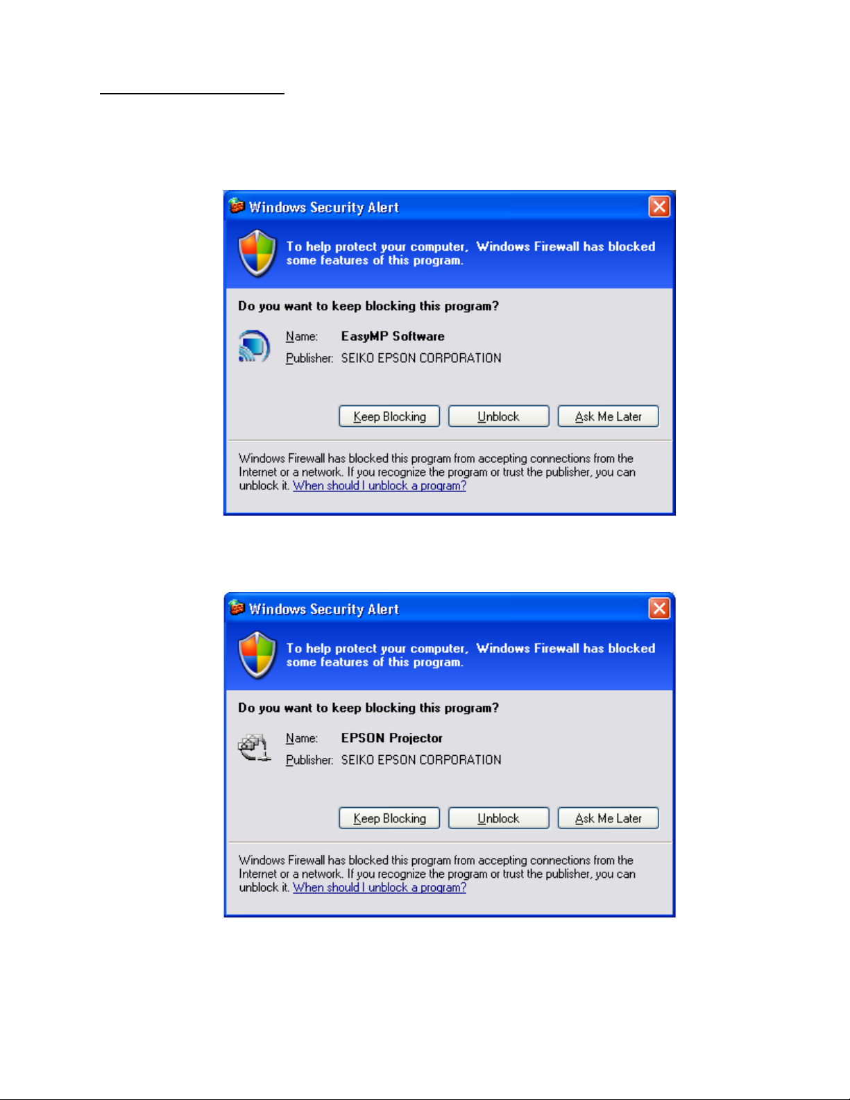
Executing the Software:
When executing the software noted below for the first time after SP2 installation completes,
the following security alert messages are displayed:
[EMP NS Connection]
Security alert screen (EMP NS Connection)
[EMP Network Manager]
Security alert screen (EMP Network Manager)
Page 2 of 14
PSB.2004.10.002
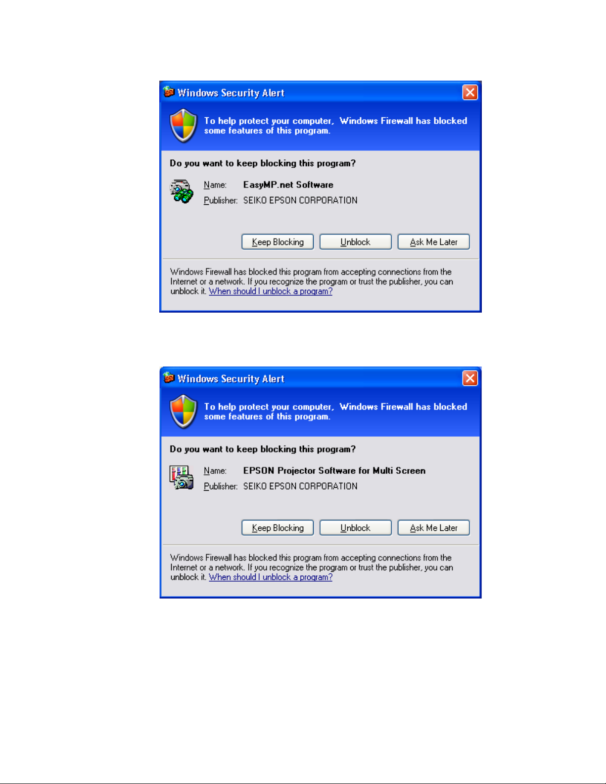
[EMP Monitor]
Security alert screen (EMP Monitor)
[EMP Multi Screen Adjustment]
Security alert screen (EMP Multi Screen Adjustment)
The Security Alert screen for
Auto
button of
IP Address
Network
box.
or clicking the
EMP Multi Screen Adjustment
Add
button after entering an IP address in the
Page 3 of 14
PSB.2004.10.002
is shown after clicking the

[Cinema Color Editor]
Security alert screen (Cinema Color Editor)
The functions of the three buttons displayed in the security alert screen are explained
below.
Keep Blocking
[
] --- Enables you to register a started application in the “
Exceptions”
program of the Windows Firewall. The network port that the
application uses is blocked. By selecting this button once, this
security alert message will not be shown when starting the
application next time.
Unblock
[
] ------------- Enables you to register a started application in the “
Exceptions”
program of the Windows Firewall and unblock the network port that
the application uses. By selecting this option once, this security alert
message will not be shown when starting the application next time.
Ask me later
[
]-------- When you want to select both buttons above or select either one
later, this button is selected. The started application is not registered
in the “
Exceptions
” program of the Windows Firewall and the
network that the application uses is not unblocked. However, when
restarting the application, the same security alert message is shown.
PC applications will work normally on Windows XP with SP2 if the “Unblock
•
Item” is selected when the security alert screen is shown.
For the detail operation information of each application, please refer to the following:
Page 4 of 14
PSB.2004.10.002
Operating Status Report
When selecting the
Keep Blocking
button, the security alert message is closed and the
main screen of each application is displayed.
[EMP NS Connection Application]
3620
Port
is necessary for searching for projectors. If this port is blocked, projectors are not
detected.
The other applications operate normally. However, there is a case that execution of
automatic search disables automatic detection. This occurs when projectors are registered
for automatic detection in EMP Monitor before installing SP2, then the registered projectors
may not be detected again after SP2 installation. Therefore it is recommended to select
Unblock
Keep Blocking”
If “
in the security alert screen.
has been selected when starting the application for the first
time, and the blocking needs to be removed, complete the execution of the application and
proceed with unblocking as follows:
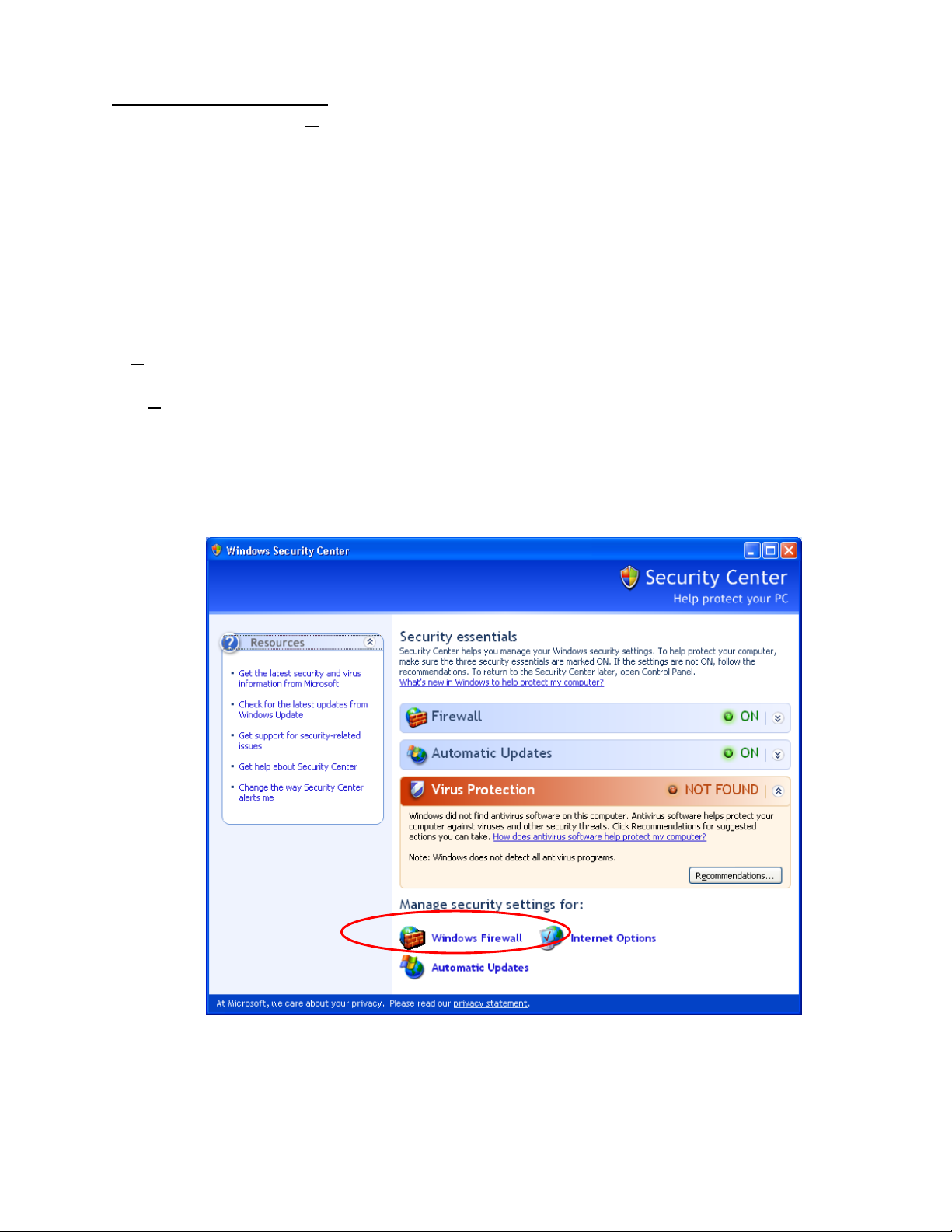
a.) Start the Windows Security Center. Double click the icon in the shape of a shield that
is always displayed on the taskbar after the installation of SP2.
b.) Select and start
Windows Security Center screen
Windows Firewall
Page 5 of 14
PSB.2004.10.002

[Caution]
In case the check box
Don’t allow
for
exceptions
is checked (this box is
not checked at the
initial setting), a
network port for
software is not
unblocked even though
the software is checked
Exceptions
on
Make sure this option is
not selected.
.
Windows Firewall screen
Page 6 of 14
PSB.2004.10.002

c.) Select the
[Caution]
If this check box is
not checked, the
security alert
screen is not
displayed when
starting software.
Exceptions
tab and display exceptions program.
•Exceptions screen
d.) Check the check boxes for the software you don’t want to block.
Page 7 of 14
PSB.2004.10.002

[EMP NS Connection] • Check
EasyMP Software
box
Unblock screen (EMP NS Connection)
Page 8 of 14
PSB.2004.10.002

[EMP Network Manager Application]• Check
EPSON Projector
box
Unblock screen (EMP Network Manager)
Page 9 of 14
PSB.2004.10.002
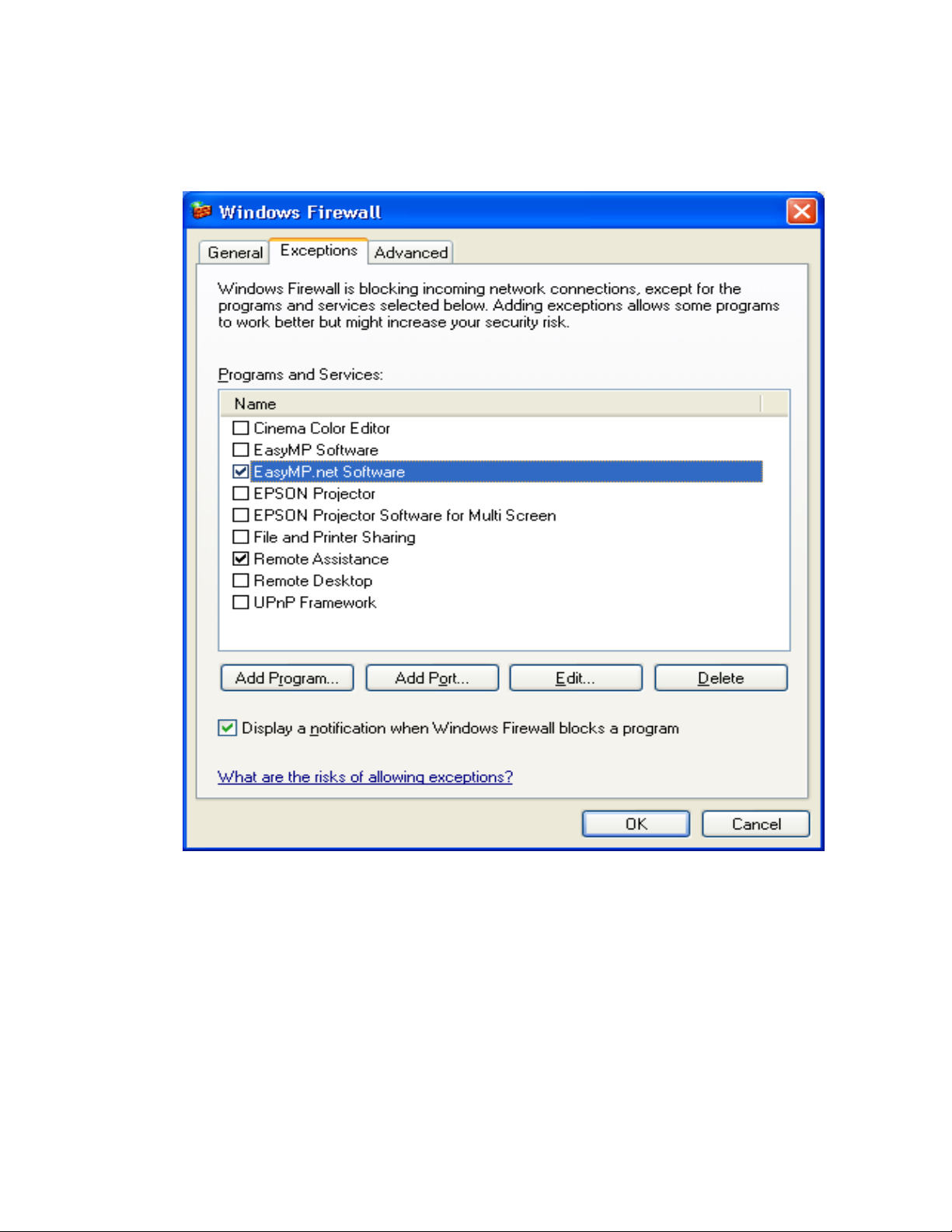
[EMP Monitor Application]→ Check
EasyMP.net Software
box
Unblock screen (EMP Monitor)
Page 10 of 14
PSB.2004.10.002
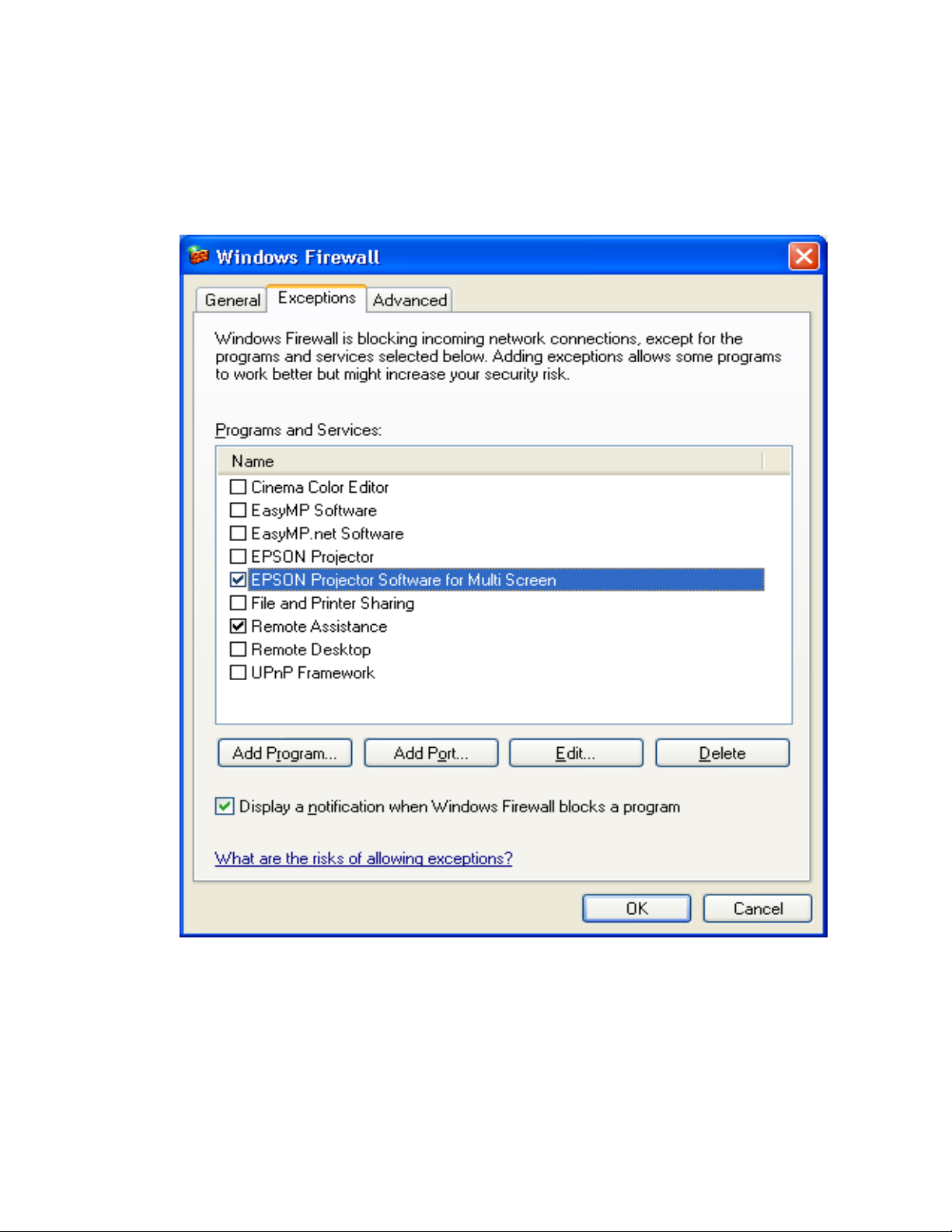
[EMP Multi Screen Adjustment Application]→ Check
Multi Screen
box
EPSON Projector Software for
Unblock screen (EMP Multi Screen Adjustment)
Page 11 of 14
PSB.2004.10.002

[Cinema Color Editor Application] ---> Check
Cinema Color Editor.
Unblock screen (Cinema Color Editor)
By following the above procedure, the network port that each application uses is unblocked
and they can operate normally.
Page 12 of 14
PSB.2004.10.002

Corresponding program name to PC applications
PC Application Program name
EMP NS Connection EasyMP Software
EMP Network Manager EPSON Projector
EMP Monitor EasyMP.net Software
EMP Multi Screen Adjustment EPSON Projector Software for Multi Screen
Cinema Color Editor Cinema Color Editor
When selecting the
Unblock
button:
The Security Alert screen is closed and the main screen is displayed. Then the search result
is displayed.
When selecting the
3620
Port
which is used by EMP NS Connection and is necessary for discovering projectors
Ask Me Later
button:
is blocked, and projectors are not detected.
The other applications operate normally. However, there is a case where execution of
automatic search disables automatic detection. This occurs when projectors are registered
for automatic detection in EMP Monitor before installing SP2, the registered projectors may
not be detected after SP2 installation.
Page 13 of 14
PSB.2004.10.002

VCOM Driver
The following message is shown after the VCOM driver is installed on your PC.
Select “No, not this time” item and continue the Plug&Play of the device.
8.) Notes:
When you add the program to Exceptions list, the program can receive network
communication from outside. This may cause a security risk such as exposure to a virus
attack.
Page 14 of 14
PSB.2004.10.002

EPSON
RODUCT SUPPORT BULLETIN
P
Date:
PSB #:
Reference:
Product(s):
Subject:
This bulletin was created to inform you of the availability of EMP Monitor version 3.03. This
version of the EMP Monitor software has added support for the PowerLite Cinema 500
projector. All other support for previously supported projectors remains the same.
This software update can be downloaded from the Epson website. Locate and download
epson11017.exe. This file is a self extracting archive that will automatically start the program
installer once the file is extracted to your computer hard drive.
Refer to the documentation provided with your projector for further information about the
operation of the EMP Monitor software.
02/26/2004
PSB.2004.02.009
TI03-57e Rev. A
PowerLite 735c / 7800p / 7850p / 8300i / Cinema 500
EMP Monitor version 3.03 Update
Originator:
Authorization:
Total Pages:
AP
1
Page 1 of 1
PSB.2004.02.009
 Loading...