

Page 1
Page 2
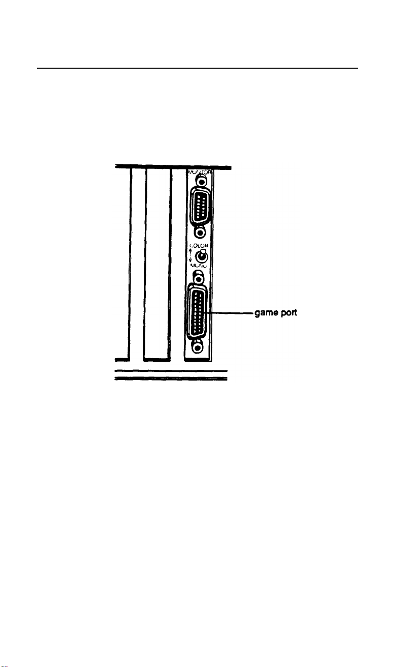
Attention Apex™ Owners
The MGA card in your computer includes a game port, such as
the one shown below. You can easily connect a joystick, track
ball, or other pointing device to this port.
Apex is a trademark of Epson America, Inc.
Copyright © 1989 by Epson America, inc.
Torrance, California
QA50189001
Page 3

IMPORTANT SAFETY INSTRUCTIONS
1.
Read all of these instructions and save them for lacer reference.
2.
Follow all warnings and instructions marked on the product.
3.
Unplug this product from the wall outlet before cleaning. Do not
use liquid cleaners or aerosol cleaners. Use a damp cloth for
cleaning.
Do not use this product near water.
4.
5.
Do not place this product on an unstable cart, stand, or table.
The product may fall, causing serious damage to the product.
6.
Slots and openings in the cabinet and the back or bottom are
provided for ventilation; to ensure reliable operation of the
product and to protect it from overheating, these openings must
not be blocked or covered. The openings should never be
blocked by placing the product on a bed, sofa, rug, or other
similar surface. This product should never he placed near or over
a radiator or heat register. This product should not be placed in a
built in installation unless proper ventilation is provided
7.
This product should he operated from the type of power source
indicated on the marking label. If you are not sure of the type of
power available, consult your dealer or local power company.
8.
This product is equipped with a 3-wire grounding-type plug, a
plug having a third (grounding) pin. This plug will only fit into a
grounding type power outlet. This is a safety feature. If you are
unable to insert the plug into the outlet, contact your electrician
to replace your obsolete outlet. Do not defeat the purpose of the
grounding type plug.
9.
Do not locate this product where the cord will be walked on.
10. If an extension cord is used with this product, make sure that the
total of the ampere ratings on the products plugged into the
extension cord Jo not exceed the extension cord ampere rating.
Also, make sure that the total of all products plugged into the
wall outlet does not exceed 15 amperes.
Page 4

11. Never push objects of any kind into this product through cabinet
slots, as they may touch dangerous voltage points or short out
parts that could result in a risk of fire or electric shock. Never
spill liquid of any kind on the product.
12. Except as specifically explained in the User’s Manual, do not
attempt to service this product yourself. Opening or removing
those covers that are marked "Do Not Remove" may expose you
to dangerous voltage points
or
other risks. Refer all servicing in
those compartments to service personnel.
13. Unplug this product from the wall outlet and refer servicing to
qualified service personnel under the following conditions:
A. When the power cord or plug is damaged or frayed.
B.
If liquid has ken spilled into the product.
C.
If the product has ken exposed to rain or water.
D.
If the product does not operate normally when the operating
instructions are followed. Adjust only those controls that
are covered by the operating instructions, since improper
adjustment of other controls may result in damage and will
often require extensive work by a qualified technician to
restore the product to normal operation.
E.
If the product has ken dropped or the cabinet has been
damaged.
F.
If the product exhibits a distinct change in performance,
indicating a need for service.
Page 5
Page 6

IMPORTANT NOTICE
DISCLAIMER OF WARRANTY
Epson America makes no representations or warranties, either express or
implied, by or with respect to anything in this manual, and shall not be
liable for any implied warranties of merchantability and fitness for a
particular purpose or for any indirect, special, or consequential damages.
Some states do not allow the exclusion of incidental or consequential
damages, so this exclusion may not apply to you.
COPYRIGHT NOTICE
All rights reserved. No part of this publication may be reproduced, stored
in a retrieval system, or transmitted, in any form or by any means,
electtonic, mechanical, photocopying, recording, or otherwise, without the
prior written permission of Epson America, inc. No patent liability is
assumed with respect to the use of information contained herein. While
every precaution has been taken in the preparation of this publication,
Epson America assumes no responsibility for errors or omissions. Nor is any
liability assumed for damages resulting from the use of the information
contained herein. Further, this publication and the features described herein
are subject to change without notice.
TRADEMARKS
ActionPrinter and Apex are trademarks of Epson America, Inc.
Epson is a registered trademark of Seiko Epson Corporation.
Hercules is a registered trademark of Hercules Computer Technology, Corp.
IBM is a registered trademark of International Business Machines Corp.
MS-DOS and Microsoft are registered trademarks of Microsoft Corp.
XTREE is a registered trademark of Executive Systems, inc.
Copyright © 1989 by Epson America, Inc.
Torrance, California
ii
Y14499103200
Page 7

FCC COMPLIANCE STATEMENT FOR AMERICAN USERS
This equipment generates and uses radio frequency energy and if not installed and
used properly, hat is, in strict accordance with the manufacturer’s instructions, may
cause interference co radio and television reception. It has been type
tested
and
found co comply with the limits for a Class B computing device in accordance with
the specifications in Subpart J of Part 15 of FCC Rules, which are designed co
provide reasonable protection against such interference in a residential installation.
However, there is no guarantee that interference will not occur in a particular
installation. If this equipment does cause interference to radio and television
reception, which can be determined by turning the equipment off and on, you are
encouraged co try co correct the interference by one or more of the following
measures:
l
Reorient the receiving antenna
l
Relocate the computer with respect to the receiver
l
Move the computer away from the receiver
l
Plug the computer into a different outlet so chat the computer and receiver are
on different branch circuits.
If necessary, consult your dealer or an experienced radio/television technician for
additional suggestions. You may find the following booklet prepared by the Federal
Communications Commission helpful:
“Television Interference Handbook.”
This booklet is available from the U.S. Government Printing Office, Washington,
DC 20402. Stock No. 004-000-00450-7.
Note:
If the interference stops, it was probably caused by the computer or its
peripheral devices. To further isolate the problem: Disconnect the peripheral devices
and their input/output cables one at a time. If the interference stops, it is caused by
either the peripheral device or its I/O cable. These devices usually require shielded
I/O cables. For Epson peripheral devices, you can obtain the proper shielded cable
from your dealer. For non-Epson peripheral devices contact the manufacturer or
dealer for assistance.
WARNING: This equipment has been certified to comply with the limits for a
Class B computing device, pursuant to Subpart J of Part 15 of FCC Rules. Only
peripherals (computer input/output devices, terminals, printers, etc.) certified co
comply with the Class B limits may be attached to this computer. Operation with
non-certified peripherals is likely to result in interference to radio and TV
reception. The connection of a non-shielded equipment interface cable to this
equipment
will invalidate the FCC Certification of this device and may cause
interference levels that exceed the limits established by the FCC for this
equipment.
This digital apparatus does not exceed the Class A/ Class B (whichever is applicable)
limits for radio noise emissions from digital apparatus as set out in the radio
interference regulations of the Canadian Department of Communications.
Le présent appareil numérique n'émet pas de bruits radioélectriques dépassant la
limites applicables aux appareils numériques de Classe A/de Classe B (selon le cas)
prescrites dans le règlement sur le brouillage radioélectriques édicté par le Ministère
des Communications du Canada.
iii
Page 8

Contents
Introduction..
How to Use This Manual
Where to Get Help
Chapter 1
1 Unpacking
Removing the Diskette Drive Protector Card
2 Choosing a Location
3 Connecting a Monitor
4 Connecting a Peripheral Device.
Using the Parallel Interface
Using the Serial interface.
5 Connecting the Power Cord
.....................................
.............................
..................................
Setting Up Your System
.......................................
.........
...............................
.............................
.....................
.......................
........................
.......................
6 connecting the Keyboard ...........................
Adjusting the Keyboard Angle.
....................
7 Turning On the Computer ..........................
8 Loading MS-DOS
Loading MS-DOS On the Apex 100
The Command Prompt
Setting the Time and Date on the Apex 100\20
9
Copying System
Copying Diskettes on the Apex 100
Copying Diskettes on the
.................................
................
...........................
Diskettes
.........................
................
Apex
100\20
.............
....
1
2
3
1-1
1-2
1-3
1-4
1-7
1-7
1-9
1-10
1-11
1- 13
1-14
1-15
1-16
1-18
1-19
1-21
1-21
1-23
Chapter 2
Changing the Operating Speed
Using
Special Keys
Using Your Computer
........................
..................................
Stopping a Command or Program
Resetting the Computer
Turning Off the Computer
..............................
.........................
.....................
Contents v
2-1
2-2
2-4
2-4
2-5
Page 9

Using Disks and Disk Drives.
How Disks Store Data
Choosing Diskettes.
..........................
...........................
.............................
Caring for Diskettes and Diskette Drives
Inserting and Removing Diskettes
Write-protecting Diskettes
Making Backup Copies
........................
...........................
Using a Single Diskette Drive
Using the Hard Disk Drive
........................
.............
..................
.....................
2-6
2-6
2-8
2-9
2-11
2-13
2-14
2-15
2-16
Chapter 3
Starting
Starting An Application Program.
Using Drive Designators
The Default Drive.
Types of MS-DOS Commands
Entering an MS-DOS Command
Creating and Managing Files
Naming Files.
Copying Files
Renaming Files
Deleting Files
Printing Files.
Using Directories.
The Default Directory
Using MS-DOS With Your Computer
and Exiting MS-DOS
.........................
......................
...............................
..............................
.........................
.......................
..........................
..................................
..................................
.................................
..................................
..................................
...................................
............................
Changing the Default Directory
Using Pathnames
...............................
Including Filenames With Pathnames
Including Drive Letters With Pathnames
and Filenames
Creating Directories
...............................
.............................
Listing the Contents of a Directory
Displaying a List of Directories.
Removing Directories.
...........................
....................
...............
.................
....................
3-2
3-2
3-3
3-3
3-4
3-6
3-8
3-9
3-10
3-12
3-13
3-14
3-15
3-17
3-17
3-18
3-19
3-19
3-21
3-22
3-23
3-24
vi Contents
Page 10

Formatting Diskettes
.................................
Formatting Diskettes on the Apex 100
Formatting Diskettes on the Apex 100\20
Formatting Diskettes With One Diskette Drive
(No Hard Disk)
Backing Up Data
....................................
Using the DISKCOPY Command
Using the BACKUP Command.
Special Epson Utilities
Using HELP
...................................
Using MENU
usingxTREE
Using an AUTOEXEC.BAT File
.............................
..................
...................
.......................
..................................
...................................
.......................
Creating an AUTOEXEC.BAT File
Using HDCACHE for the Hard Disk.
...................
..............
...........
................
3-25
3-26
3-27
3-28
3-29
3-29
3-33
3-34
3-34
3-36
3-39
3-43
3-44
3-45
Chapter 4
Removing the
Installing
Cover.
Inserting an Option Card
Option Cards
................................
.............................
Removing an Access Slot Cover
Removing an Option Card
Replacing the
Cover
Post-installation Setup
............................
.................................
...............................
Optional Disk Drive Controllers
Installing the Optional Controller
Changing the Jumper Setting.
Chapter 5
The Computer
The Computer Locks Up
Keyboard Problems
Monitor Problems
Diskette Problems
Diskette Drive Problems
Hard Disk Problems.
Troubleshooting
Won’t Start
...........................
..............................
..................................
...................................
...................................
..............................
.................................
...................
.......................
..................
.....................
4-2
4-4
4-7
4-8
4-8
4-9
4-10
4-11
4-12
5-1
5-2
5-3
5-3
5-5
5-8
5-9
Contents vii
Page 11

Software
Problems
Printer Problems
...................................
....................................
Option Card Problems
................................
5-11
5-12
5-13
Appendix A
Changing the DIP Switches
DIP Switch Set 1 (Internal Operations)
Changing DIP Switches and Using Setup
...........................
............. A-2
DIP Switch Set 2 (Parallel and Serial Port Operations).
Running the Setup Program
Starting Setup
..................................
Setting the Real-time Clock.
Changing Serial Port Settings
Leaving the Setup Program
Appendix B
Main Unit
Keyboard
Massstorage
Power Supply
Specifications
.....................................
......................................
...................................
..................................
Environmental Requirements.
Physical Characteristics
Video and Display Options.
Other Apex Options.
Parallel Port Pin Assignments
Serial Port Pin Assignments.
Keyboard
Connector Pin Assignments
...........................
......................
.....................
.......................
.....................
..........................
.......................
............................
.....................
......................
..............
Parallel Port Loop-back Connector Pi Assignments
Serial Port Loop-back Connector Pin Assignments
...
....
A-1
A-4
A-6
A-6
A-8
A-10
A-13
B-1
B-2
B-2
B-3
B-3
B-3
B-4
B-4
B-7
B-8
B-9
B-9
B-9
viii Contents
Page 12

Appendix C
Power-on Diagnostics
System
Device Check
Timer and CMOS RAM Check.
RAM Check
.......................................
Keyboard Controller and Keyboard Check.
Floppy Disk Drive Seek Check.
Appendix D
Performing System Diagnostics
Starting System Diagnostics
Modifying the DEVICE LIST
Selecting a Test
Resuming From an Error
System Board Check
Memory Check
Keyboard Check
................................
.......................
...............
........................
...........................
..........................
.....................................
..........................
.................................
...................................
....................................
Monochrome Display Adapter and CRT Check
Monochrome Adapter Check.
Attribute Check
Character Set Check
Video Check
Sync Check
................................
............................
...................................
....................................
Run All Above Checks
Color Graphics Adapter and CRT Check
Color Graphics Adapter Check
Attribute Check
Character Set Check
................................
............................
40-column Character Set Check
320x200 Graphics Mode Check.
640x200 Graphics Mode Check.
Screen Paging Check
Light Pen Check
Color Video Check
Sync Check
...................................
............................
................................
..............................
Run All Above Checks
.....................
..........................
................
....................
...................
...................
...................
..........................
...........
C-1
C-2
C-3
C-3
C-4
D-1
D-3
D-5
D-6
D-7
D-8
D-9
D-10
D-11
D-12
D-12
D-13
D-13
D-13
D-14
D-15
D-15
D-16
D-17
D-17
D-18
D-19
D-20
D-21
D-21
D-21
Contents ix
Page 13

Floppy Disk Drives and Controller Check
................
Formatting a Diskette ...........................
Starting the Floppy Disk Drive Check
Sequential Seek Check
Random Seek Check
Write, Read Check
Speed Check
...................................
Run All Above Checks
..........................
............................
..............................
..........................
Math Coprocessor Check (8087-1)
.....................
..............
Parallel Port (Printer Interface) Check ..................
Parallel Port (on Video Adapter) Check
Serial Port (RS-232C) Check
Alternate Serial Port Check
..........................
...........................
.................
Dot-matrix Printer Check. ............................
Hard Disk Drives and Controller Check
Seek Check
....................................
.................
Write, Read Check .............................
Error Detection and Correction Check
..............
Read, Verify Check .............................
Run All Above Checks
Error Codes and Messages
..........................
.............................
D-22
D-22
D-23
D-24
D-24
D-25
D-25
D-26
D-26
D-27
D-28
D-28
D-30
D-30
D-31
D-32
D-33
D-34
D-34
D-35
D-36
Appendix E
Physically Formatting a Hard Disk
Formatting and Checking Options
Reformatting a Used Disk
Formatting a New Disk
........................
...........................
Starting the Formatting Process
Conditional Format (Normal)
Unconditional Format
...............................
Destructive Surface Analysis
.........................
...........................
Non-destructive Surface Analysis.
x
Contents
.....................
....................
......................
E-2
E-3
E-4
E-4
E-5
E-7
E-10
E-11
Page 14

Appendix F
Preparing a Hard Disk for Use
Creating the MS-DOS Partition
Formatting the MS-DOS Partition
.......................
......................
Copying the Remaining Files to the Hard Disk
Creating the AUTOEXEC.BAT File
Booting From the Hard Disk.
..........................
..........................
Glossary
Index
............
F-2
F-4
F-6
F-7
F-8
Contents xi
Page 15

Introduction
Your Apex” personal computer is powerful, versatile, and easy
to use. After setting up your system with the simple instructions
in this manual, you’ll soon be using your favorite software
programs.
The Apex computer is available in these configurations:
The Apex 100 provides two 360KB (kilobyte) diskette
drives
The Apex 100\20 provides one 20MB (megabyte) hard
disk drive and one 360KB diskette drive.
Both models come with 640KB of internal memory, five
internal option slots, an MGA (multi-graphics adapter) card,
and built-in serial and parallel interfaces. You can connect
either a monochrome or color graphics monitor to the MGA
card in the computer.
Your computer comes with version 3.3 of MS-DOS®—an
operating system by Microsoft.® In addition to the introduction
to MS-DOS provided in this manual, you’ll find a
comprehensive reference manual for the operating system
pack4 in the box with your computer.
As a supplement to MS-DOS, Epson has included several time-
saving utilities that make MS-DOS easier to use: HELP,
MENU, and XTREE.® The HELP program lets you display
information on the screen about any MS-DOS command.
MENU provides an easier way to run many of the most
common MS-DOS commands. XTREE is a file management
utility that simplifies all file and directory operations; it is
especially useful for managing data on a hard disk.
Introduction 1
Page 16

As your needs grow, so can your computer; you can expand your
system by adding a wide variety of options. You can install most
option cards compatible with the IBM” Personal Computer.
For example, you can add an internal modem card to provide
data communications. If you use software that executes lengthy
mathematical calculations, you may want to install an 8087-1,
10 MHz math coprocessor to speed up processing.
How to Use This Manual
This manual explains how to set up and care for your computer.
It also describes how to use your computer and run diagnostic
checks. The instructions in this manual apply to both models
of the Apex computer except where indicated otherwise.
You probably don’t need to read everything in this book; see
the following chapter summaries.
Chapter 1 provides simple step-by-step instructions for setting
up your computer. On the back cover foldout are illustrations
identifying the different parts of the computer; you may want
to refer to this while you are setting up your system.
Chapter 2 covers some general operating procedures, including
how to use and care for your disks and disk drives.
Chapter 3 provides basic instructions for using MS-DOS with
your computer.
Chapter 4 describes how to install option cards in your computer.
Chapter 5 contains troubleshooting tips in case you encounter
any problems while using your computer.
Appendix A explains how to change the DIP switch settings
and run the Setup program if you modify your computer’s
configuration.
Appendix B gives the technical specifications for the computer.
2 Introduction
Page 17

Appendix C provides information on the power-on diagnostics.
Appendix D outlines the system diagnostic checks you can
perform on your computer. If you are having trouble with any
part of the hardware, you may want to run some of these
diagnostic checks.
Appendix E describes how to perform a hardware-level format
on the hard disk. You need to do this only if you are having
serious problems with the hard disk in your Apex 100\20 or if
you have installed a new hard disk that has not received this
type of format. (This is not the same type of format provided by
the MS-DOS FORMAT command.)
Appendix F explains how to prepare a new hard disk for use.
You need to follow these instructions only if you have installed
a new hard disk
or reformat the one you have been using.
At the back of the manual you’ll find a glossary of computer
terms and an index.
in
your computer or if you need to repartition
Where to Get Help
Customer service for Epson products is provided by a network
of authorized Epson Customer Care Centers throughout the
United States.
Call the Epson Consumer Information Center at
1-800-922-8911 for the following:
Customer Care Center referrals
Technical support referrals
Information on Epson User Groups.
To locate or purchase accessories or supplies, contact your
nearest Epson dealer or call 1-800-873-7766.
Introduction 3
Page 18
Chapter 1
Setting Up Your System
Setting up your Apex personal computer is easy. Just follow the
nine steps in this chapter. You may want to leave the back
cover foldout open so you can refer to the two illustrations
identifying the different parts of the computer.
Note:
If you have experience setting up computers, you may prefer
to follow the brief instruction on the Read This First card
included with this manual. (Turn to this chapter if you have
any questions and for instructions on copying your system
diskettes.)
Unpacking
1
As you unpack the different parts of your computer system, be
sure to inspect each piece. If anything is missing or looks
damaged, contact the place where it was purchased for missing
items or replacements. If you cannot obtain the necessary part
or parts, call your Epson Customer Care Center. Please have
the computer’s serial number ready when you call.
Setting Up Your System
1-1
Page 19

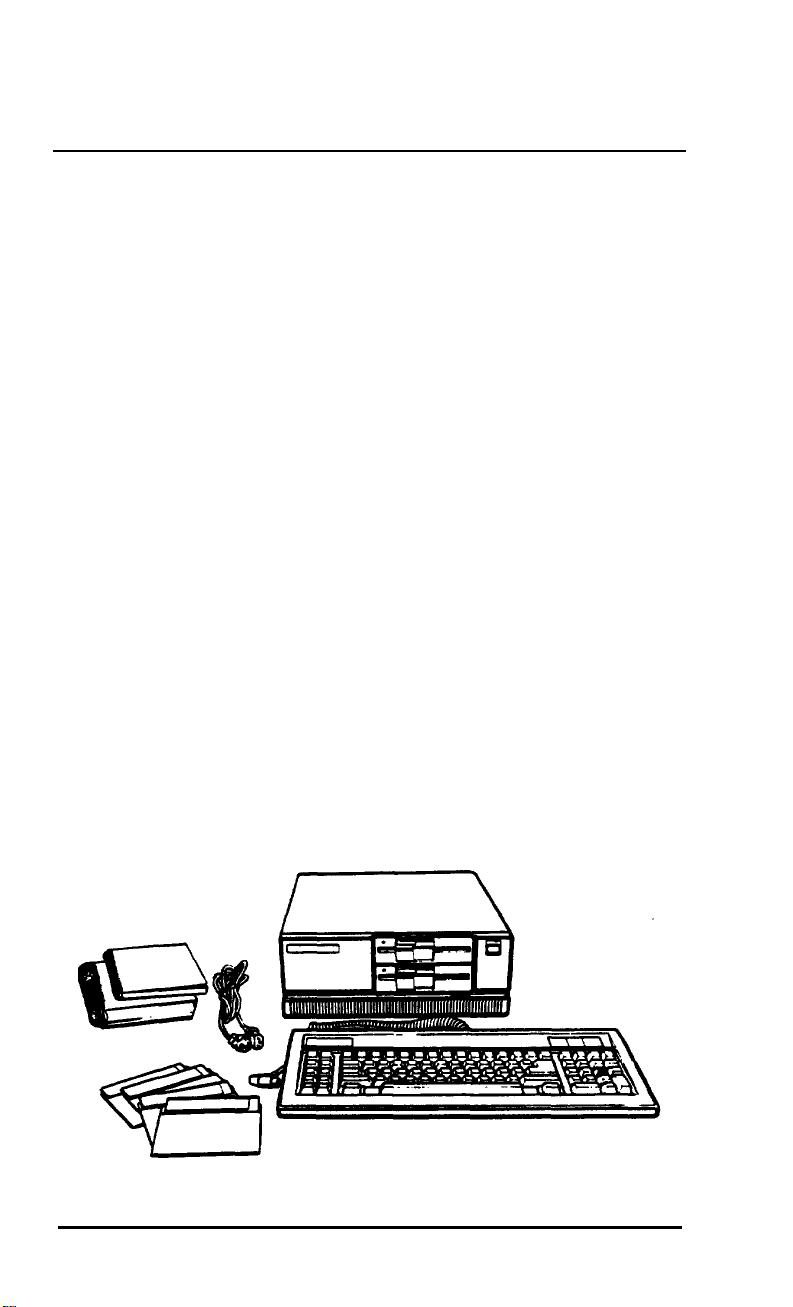
Besides this manual, you should have the following:
The computer and power cord
The keyboard with attached cable
Four diskettes: three that contain the MS-DOS operating
system (Startup, Operating 1, and Operating 2), and a
Reference diskette
An MS-DOS Reference Manual.
In addition to these items, you need a compatible video
monitor to use with the computer. With the MGA (multi-
graphics adapter) card in the computer, you can use a
monochrome or color graphics monitor.
Note
If you chose a monitor that is not compatible with the MGA
card, you'll also need the appropriate display adapter card to
use with that monitor.
You’ll find a warranty card and a registration card with the
computer. Fill out the registration card and mail it to Epson.
With this card on file, Epson can send you update information.
Be sure to keep your packing materials. They provide the best
protection for your computer if you need to transport it later.
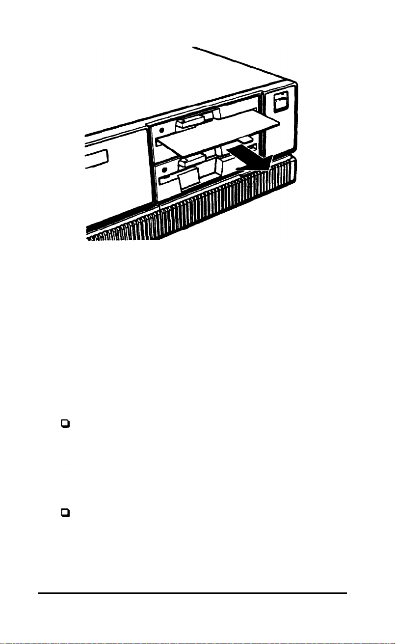
Removing the Diskette Drive Protector Card
A protective piece of cardboard occupies the slot of each
diskette drive in your computer. This card is inserted at the
factory to protect the read/write heads in the drive.
Be sure to remove the card from each diskette drive before you
turn on the computer. Turn the diskette drive latch up until it
is horizontal and carefully pull out the card.
1-2
Setting Up Your System
Page 20
Save
the protector
computer. If you don’t plan to use your computer for a week or
more, reinsert
disk drive.
card
and reinsert it whenever you
the card to help prevent dust from entering the
move
Choosing a Location
2
Before you set up your computer, it is important to choose the
right location. Select a spot that provides the following:
A large, sturdy desk or table that can easily support the
weight of your system, including all its components. Make
sure the surface is hard and flat. Soft surfaces like beds and
carpeted floors
data on your disks and damage the computer’s circuitry.
Soft surfaces also prevent proper ventilation.
attract static
electricity, which
can erase
the
Good air circulation.
the system as well as behind it. Leave several inches of
space around the computer to allow ventilation.
Air must be able to move freely under
Setting Up Your System
1-3
Page 21

Moderate environmental conditions. Protect your
computer from extremes in temperature, direct sunlight, or
any other source of heat. High humidity also hinders
operation, so select a cool, dry area. Avoid dust and smoke,
which can damage disks and disk drives and cause you to
lose valuable data.
Appropriate power sources. To prevent static charges,
connect all your equipment to three-prong, 120-volt
grounded outlets. You need one outlet for the computer,
one for the monitor, and additional outlets for a printer
and any other peripherals. You can plug one peripheral into
the auxiliary power outlet on the back panel of the
computer, reducing the number of wall outlets you need.
(The current required by the peripheral must not exceed
1 amp.)
No electromagnetic interference. Locate your system away
from any electrical device, such as a telephone, that
generates an electromagnetic field.
Connecting a Monitor
Your computer comes with an MGA (multi-graphics adapter)
card installed. This card controls the monitor and provides the
connection to attach the monitor to the computer. You can
connect a monochrome or color graphics monitor to this card.
Note
If you are using another type of monitor with your
computer—such as an EGA (enhanced grapics adapter) or
VGA (video graphics array)—you need a compatible display
adapter card to control if. If the optional card is not already
installed in the computer, you need to do this before you can
connect the monitor. See Chapter 4 Fox instructions on
installing an option card (in this case, the video card).
1-4
Setting Up Your System
Page 22
The procedure you use to connect your monitor to the
computer depends on the type of monitor you have. See your
monitor manual for detailed instructions or follow these
general guidelines:
1.
Place your monitor on top of or near the computer. It is
easiest to connect the monitor cable if the backs of the
monitor and the computer are facing you.
2.
If necessary, connect the monitor cable to the monitor.
(Some monitors-such as the Apex-come with
permanently attached cables.)
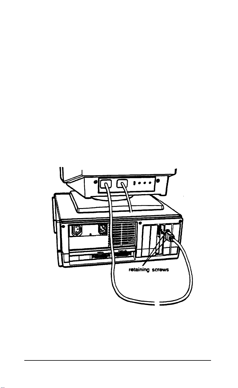
3.
Connect the monitor cable to the video card connector on
the back of the computer, as shown below. If the plug has
retaining screws, tighten them by hand or with a
screwdriver, depending on the screw type.
4.
If necessary, plug the monitor’s power cord into the
monitor’s power inlet.
Setting Up Your System
1-5
Page 23
5.
Plug the other end of the power cord into an electrical
outlet.
Note
If the monitor has the proper type of plug, you can plug
at into the auxiliary power outlet next to the AC power
inlet on the back of the computer.
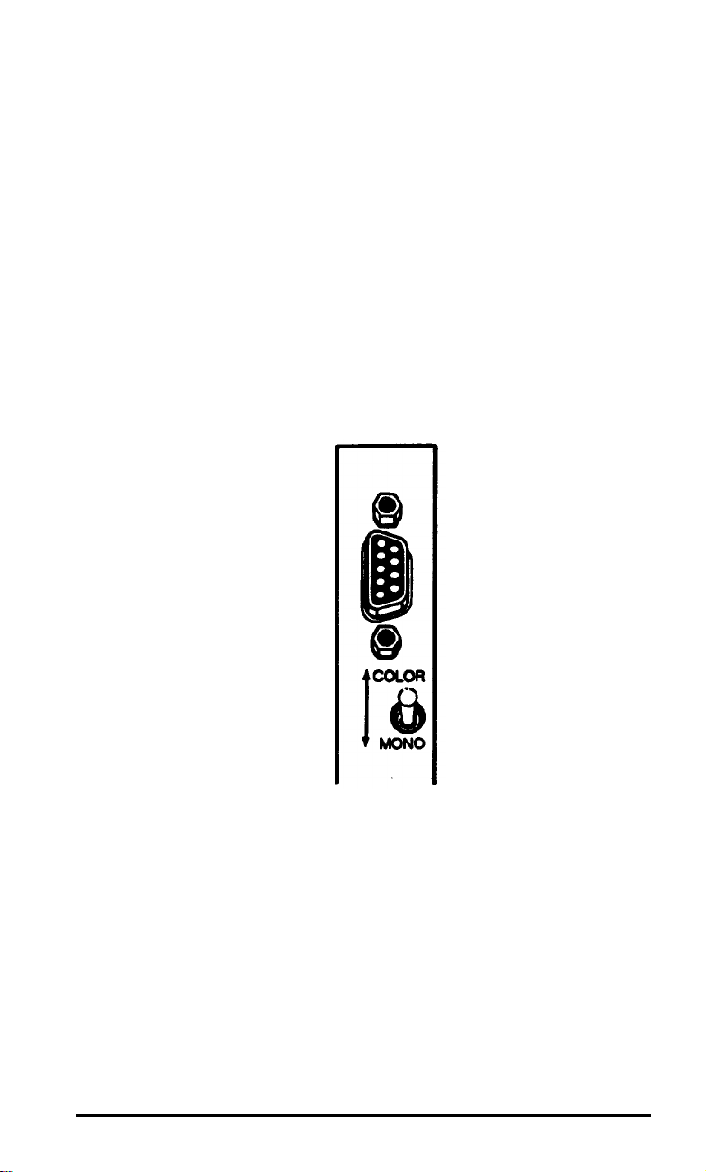
6.
If you connected the monitor to the MGA card in the
computer, set the color/mono monitor switch on the card
to match the type of monitor you are using, either color or
monochrome.
7.
The Apex computer is set up to use an 80-column, color
monitor. If you are connecting any other type of monitor,
you need to change two of the DIP switches (1-5 and 1-6)
on the computer’s front panel to match the monitor and
display adapter you are using. See Appendix A for
instructions on changing the DIP switches.
1-6 Sating Up Your System
Page 24

Connecting a Peripheral Device
4
The computer has a parallel interface and a serial interface on
the back panel; so you can easily connect a printer or other
device with either type of interface.
For example, you can use the parallel port to connect a parallel
printer; most printers have a parallel interface. You can use the
serial port to connect a serial printer, a serial mouse, or an
external modem.
Follow the steps in this section to connect a printer or other
peripheral device to either the parallel or serial interface.
Using the Parallel Interface
The parallel interface on the computer is Centronics
compatible and uses a 25-pin connector. To connect a parallel
printer to your computer, you need an IBM-compatible printer
cable. If you are not sure which one you need, check with the
store where you purchased the computer.
®
Once you have the correct printer cable, follow these steps to
connect the printer to the parallel interface on the computer:
1.
Place the printer next to your computer.
2.
One end of the printer cable has a 25-pin, male connector.
Connect this end to the parallel port on the back panel of
the computer, as shown in the following illustration. If the
plug has retaining screws, tighten them by hand or with a
screwdriver, depending on the screw type.
Setting Up Your System
1-7
Page 25
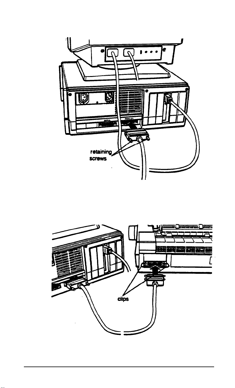
3.
Connect the other end of the cable to the printer as shown
below. If the printer has retaining clips on each side of the
printer port, squeeze them together to secure the cable.
4.
Plug the printer’s power cord into an electrical outlet.
1-8
Setting Up Your System
Page 26
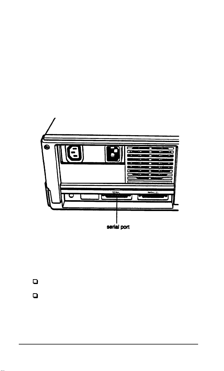
Using the Serial Interface
If you have a printer, modem, mouse, or any other peripheral
with a serial interface, you can connect it to the serial
(RS-232C) port on the back of the computer. The Apex uses a
25-pin male connector, so be sure you have the proper cable. If
you are not sure, check with the store where you bought the
computer and printer.
To connect a serial device, follow the same steps outlined
above for a parallel device, but connect the cable to the serial
port.
Setting up the serial port for a printer
If you are using a serial printer but your software does not
support a serial printer, you must do two things before you can
use the serial printer:
Set up the data transmission parameters for the port
Tell the computer to redirect printer data from the parallel
port to the serial port.
Setting Up Your System
1-9
Page 27
The Setup program on your Reference diskette lets you define
the baud rate, parity, data length, and number of stop bits for a
primary and a secondary serial port. See “Running the Setup
Program” in Appendix A for instructions.
To redirect the printer data you can use either the MS-DOS
MODE command or the Epson MENU utility. (MENU
provides an easy way to use MODE. For instructions, see the
description of the Mode Settings option of the MENU program
in your MS-DOS Reference Manual.)
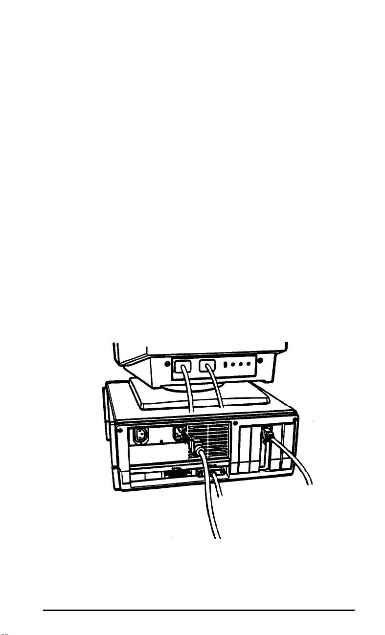
Connecting the Power Cord
5
Follow these steps to connect the power cord:
1.
Insert the power cord into the AC power inlet on the back
panel, as shown below. To avoid an electric shock, be sure
to plug the cord into the computer before plugging it into
the wall socket.
2.
Plug the other end of the power cord into a three-prong,
120-volt, grounded electrical outlet.
1-10 Setting Up Your System
Page 28
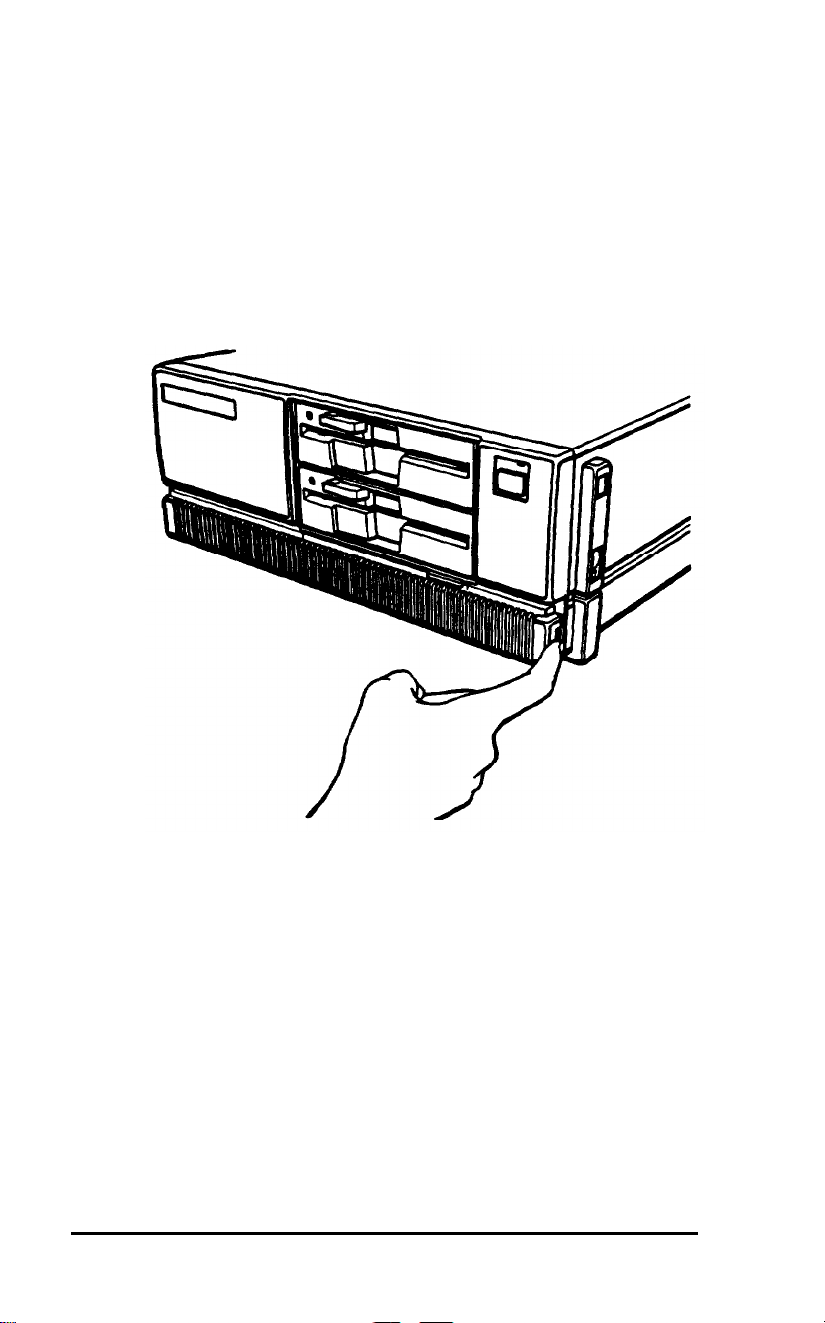
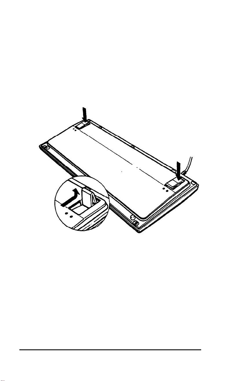
Connecting the Keyboard
6
Follow these steps to connect the keyboard:
1.
Facing the front of the computer, open the cover on the
lower right comer; use the tip of your finger to pull it open
from the right side.
Setting Up Your System
1-11
Page 29
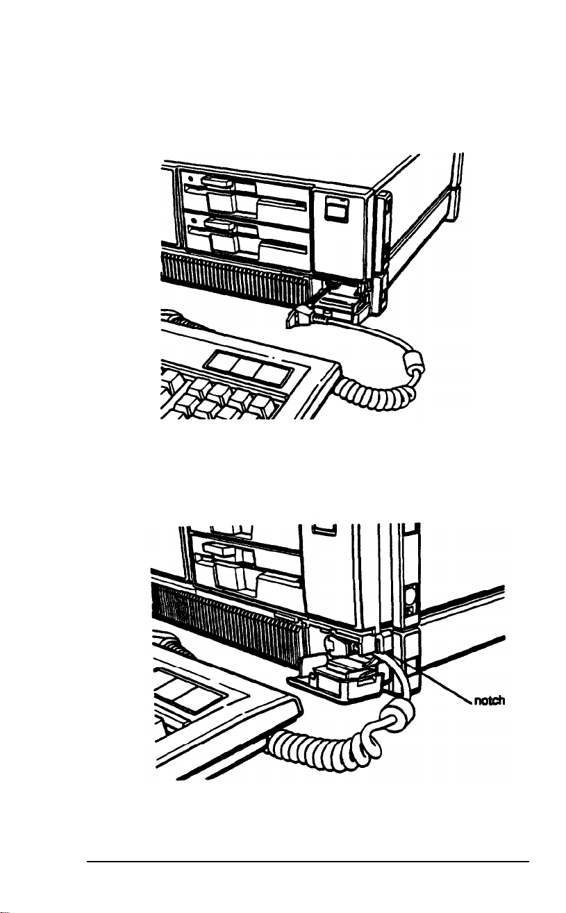
Plug the keyboard cable into the socket, as shown below.
2.
Do not force the connector, but be sure to insert it all the
way.
Push the cable into the notch at the right side of the
3.
computer, as shown below, so the cable leads away to the
right side of the computer.
1-12
Close the keyboard cable cover.
4.
Setting Up Your System
Page 30
Adjusting the Keyboard Angle
You can change the angle of the keyboard by adjusting the legs
on the bottom. Follow these steps:
1. Turn the keyboard over.
2.
Press down on the front part of each leg, as shown below,
and then use your thumbs to lift up the legs until they lock
into place.
3.
Turn the keyboard right-side up.
Setting Up Your System
1-13
Page 31

Turning On the Computer
7
Before you turn on your computer, read the following safety
rules to avoid accidentally damaging the computer or injuring
yourself:
Never turn the computer on with a protector card in the
diskette drive.
Do not unplug cables from the computer when the power
switch is on.
Never turn off or reset your computer while a disk drive
light is on. This can destroy data stored on disk or make a
whole disk unusable.
Always wait at least five seconds after you switch off the
power before you switch it on again. Turning the power off
and on rapidly can damage the computer’s circuitry.
Do not leave a beverage on top of or next to your system or
any of its components. Spilled liquid can damage the
circuitry of your equipment.
Do not attempt to dismantle any part of the computer.
Only remove the cover to install and remove optional
devices. If there is a hardware problem you cannot solve
after reading the appropriate section in Chapter 5 on
troubleshooting, contact your Epson Customer Care
Center.
Always turn off the power, disconnect all cables, and wait
five seconds before you remove the computer’s cover.
Follow these steps to turn on your system:
1.
Turn on the monitor, printer, and any other peripheral
devices connected to the computer.
1-14 Setting Up Your Systems
Page 32

2.
To turn on the computer, press the power
The power indicator on the front panel lights up. After a few
seconds, the computer starts to perform an internal self test.
This is a series of checks the computer completes each time you
turn it on to make sure everything is working correctly. If
anything is wrong, an error message appears on the screen.
If you cannot see the screen display clearly, use the controls on
your monitor to adjust the brightness and contrast until
characters on the screen are clear and bright.
switch.
Loading MS-DOS
8
Once the computer completes its self test, it tries to load
MS-DOS, the operating system, into the computer’s memory.
MS-DOS must be in the computer’s memory before you can
run any application program-such as a word processing
program or a spreadsheet program.
If you have the Apex 100\20, the computer automatically
loads MS-DOS from the hard disk and you see the MS-DOS
command prompt on the screen:
C:\>
Go on to the section below called “The Command Prompt.”
Setting Up Your System 1-15
Page 33

If you have the Apex 100 (no hard disk), the computer does
not load MS-DOS, but instead displays the following:
Non-system disk or disk error
Insert system diskette in drive A
and strike any key when ready
These messages tell you that you need to insert the MS-DOS
Startup (system) diskette in the top drive, drive A, so the
computer can load the operating system. Follow the
instructions below.
Note
You can turn on the computer with Startup diskette in the
drive. If you do this, the computer loading MS-DOS form
the diskette and you do not see the error message.
Loading MS-DOS On the Apex 100
Follow these steps to load MS-DOS from a diskette in drive A:
1.
Insert the Startup diskette into drive A (the top diskette
drive), as shown below. Hold the diskette with the label
facing up and the read/write slot leading into the drive.
1-16 Setting Up Your System
Page 34

When the diskette is in all the way, turn the latch down
2.
(clockwise) to lock the diskette in place. (For detailed
instructions on inserting diskettes, see Chapter 2.)
Press any key. The computer loads MS-DOS into its
3.
memory where it will remain until you turn off the
computer. Once MS-DOS is loaded, you see a date prompt,
such as the following, which appears every time you load
MS-DOS:
Current date is Mon 7-24-1989
Enter new date (mm-dd-yy):
If the date is correct, press
4.
correct the date, enter it in the order shown, using one or
two digits for the month, day, and year, separated by
dashes. For example, to set the date for August 30, 1989,
you would type the following:
Enter
to leave it unchanged. To
8-30-89
Next the screen displays the time prompt, such as this:
5.
Current time is 09:32:21.77
Enter new time:
If the time is correct, press
correct the time, use a 24-hour clock to enter the time in
the format shown, using one or two digits for each part
(you can omit the seconds, if desired). For example, to
change the time to 1:30 p.m., you would type the following:
Enter
to leave it unchanged. To
13:30
The screen displays the MS-DOS command prompt:
A>
Setting Up Your System 1-17
Page 35

You need to set the date and time this way only once; the
computer’s real-time clock keeps track of the date and time
even when the computer is off. The next time you load
MS-DOS, you can
just
press
Enter
when you see each of
these prompts to accept the displayed date and time.
MS-DOS updates months and years correctly-whether the
month has 31, 30, 29, or 28 days—and even accounts for leap
years. You may
accommodate a change
Note
You can also change the date and time with the Setup
program or with the MS-DOS DATE and TIME commands.
The Setup program is described in Appendix A. The DATE
and TIME commands are described below for the Apex
100\20 and in the MS-DOS manual.
need
to change the time later, however, to
such
as daylight savings time.
The Command Prompt
The command prompt tells you that MS-DOS is loaded and
your computer is ready to receive instructions. It also identifies
the current operating drive: A, B, or C. The command prompt
appears on the screen whenever you load MS-DOS, complete
an MS-DOS command, or exit an application program.
On the Apex 100, the top diskette drive
is
drive A and the
bottom diskette drive is B. On the Apex 100\20, the diskette
drive is A and the hard disk is drive C. MS-DOS reserves the
label B for a second diskette drive, whether or not it is
installed.
If you load MS-DOS from a diskette in drive A, the command
prompt looks like this:
A>
1-18
Setting Up Your System
Page 36

If you load MS-DOS from the hard disk, the command prompt
looks like this:
C:\>
The hard disk prompt is different because the Apex
been set up with a special command that changes the
command prompt to show the current directory. (A directory
consists of a group of files stored together under an identifying
name. See Chapter 3 for a complete description of directories.)
The command that changes the command prompt is called
PROMPT and it is stored in a file called AUTOEXEC.BAT.
The AUTOEXEC.BAT file contains a series of commands that
your computer performs each time it loads MS-DOS. You can
add commands to this file to automate a set of procedures you
normally perform each time you turn on the computer. See
Chapter 3 for more information about using the
AUTOEXEC.BAT file.
Note
For consistency, this manual uses the same format for the
command prompt for both drive A and drive C, that is: A>
and C>.
100\20
has
Setting the Time and Date on the Apex 100\20
The first time you use your Apex 100\20, you need to set the
correct date and time for the computer’s real-time clock.
Follow these steps:
1.
At the C> prompt,
displays the following:
type DATE
and press
Enter.
Current date is Mon 7-24-89
Enter new date (mm-dd-yy):
Setting Up Your System
The screen
1-19
Page 37

2.
If the date is correct, press
change the date, type the appropriate numbers for the
month, day, and year, as shown. For example, to set the
date for August 30, 1989, type the following and press
Enter:
8-30-89
Enter
to leave it unchanged. To
3. Next type
following:
TIME
and
press Enter.
The screen displays the
Current time is 09:32:21.0
Enter new time:
If the time is correct, press
To change it, enter the time in the format shown using a
24-hour clock. You can omit the seconds, if desired. For
example, to change the time to 1:30 p.m., type the
following and press
Enter:
Enter
to leave it unchanged.
13:30
You need to set the date and time this way only once; the
computer’s real-time clock keeps track of the date and time
even when the computer is off. it updates months and years
correctly-whether the month has 31, 30, 29, or 28 days-and
accounts for leap years. You may need to change the time later,
however, to accommodate a change such as daylight savings
time.
Note
You can also change the date and time with the Setup
program, described in Appendix A.
1-20
Setting UP Your System
Page 38

Copying System Diskettes
9
Now that you have set up your system and loaded MS-DOS, it
is important that you make copies of your MS-DOS and
Reference diskettes right away. Use only the copies (usually
called “working copies”) for daily use and store the originals in
a safe place.
The procedure for copying diskettes depends on the number of
diskette drives you have. Follow the instructions below for your
model. You’ll need four blank, 360KB, double-sided, doubledensity, 5 1/4-inch diskettes.
Note
If your computer has only one diskette drive and no hard
disk, follow the instructions in Chapter 3 for copying
diskettes with only one drive.
Be sure to label each diskette as you copy it. Write on the label
before you attach it to the diskette to prevent damaging the
diskette.
Copying Diskettes on the Apex 100
1.
The
A>
prompt should be on the screen; if it is not, follow
the steps in the previous section, “Loading MS-DOS on the
Apex 100.”
2.
Remove the Startup diskette from the cop drive by turning
the latch up and pulling out the diskette. Then insert the
diskette labelled “Operating 1” and turn the latch down to
secure the diskette. The Operating 1 diskette contains the
DISKCOPY program which you will use to make the
copies.
Setting Up Your System
1-21
Page 39

3.
Insert a blank 5 1/4-inch 360KB diskette in drive B (the
bottom drive) and turn the latch down to secure the
diskette.
4.
Type the following and press
Enter.
DISKCOPY A: B:
The screen displays these prompts:
Insert SOURCE diskette in drive A:
Insert TARGET diskette in drive B:
Press any key when ready ...
5.
Drive A (the top drive) already contains a diskette you
want to copy (the source diskette) and drive B contains the
blank target diskette, so just press any key. The
DISKCOPY program begins the copy process.
If the diskette in drive B is not formatted, the DISKCOPY
program formats it. (Formatting prepares a diskette to store
data and is described in Chapter 3.) Then the program
copies the contents of the diskette in drive A to the
formatted diskette in drive B. When the copy is complete,
you see this prompt:
Copy another diskette (Y/N)?
6.
Press Y so you can make a copy of the Operating 2 diskette.
Again, you see these prompts:
Insert SOURCE diskette in drive A:
Insert TARGET diskette in drive B:
Press any key when ready . . .
7.
Remove the original Operating 1 diskette from drive A and
the copy from drive B. Insert the Operating 2 diskette in
drive A and another blank diskette in drive B. Then follow
the instructions above and the prompts on the screen to
make a copy of this diskette.
1-22 Setting Up Your System
Page 40

8.
Repeat the procedure for the Startup diskette and the
Reference diskette.
9.
When you finish copying the last system diskette and the
Copy another diskette (Y/N)? prompt
appears, press N to return to the MS-DOS command
prompt.
Copying Diskettes on the Apex l00\20
1.
The
C>
prompt should be on the screen; if it is not, type
C
: and press
2.
Type the following and press
Enter.
Enter:
DISKCOPY A: A:
The screen displays these messages:
Insert SOURCE diskette in drive A:
Press any key when ready . . .
3.
insert the Startup diskette in drive A (the diskette drive),
as shown below, with the label facing up and the read/write
slot leading into the drive.
Setting Up Your System
1-23
Page 41

Then press
contents of the Startup diskette to the computer’s memory,
and then you see the following:
any key. The DISKCOPY program copies the
Insert TARGET diskette in drive A:
Press any key when ready . . .
4.
Remove the Startup diskette and insert a blank diskette
(which is to be the target) in the drive. Then press any key.
If the diskette is not formatted, the DISKCOPY program
formats it. (Formatting prepares a diskette to store data and
is described in Chapter 3.) Then the program begins
copying the data from the computer’s memory to the
formatted diskette. When the copy is complete, you see
this prompt:
Copy
another diskette (Y/N)?
5.
Press Y so you can make a copy of the Operating 1 diskette.
Again, you see the prompt to insert the source diskette.
6.
Remove the copy of the Startup diskette, which you just
made, and insert the Operating 1 diskette in the drive.
Then press any key. Continue following the prompts on
the
screen
Startup diskette.
to make a copy of this diskette, as you did the
7.
Repeat the procedure to copy the Operating 2 diskette and
then the Reference diskette.
8.
When you finish copying the last diskette and the
another diskette (Y/N)?
N to return to the MS-DOS command prompt.
1-24 Setting Up Your System
Copy
prompt appears, press
Page 42

Chapter 2
Using Your Computer
This chapter covers the following basic procedures for using
your computer:
Changing the operating speed
Using special keys on the keyboard
Interrupting a command or program
Resetting and turning off the computer
Using disks and disk drives.
Changing the Operating Speed
Your computer can operate at two speeds: 4.77 MHz or
10 MHz. At 10 MHz, the computer performs all tasks faster,
and you will probably use this speed for almost everything you
do. Certain application programs, however, have specific
timing requirements for diskette access and can run only at the
slower speed. See the manual for your application program to
determine if this is the case.
Use the
To access the switch, open the cover below the disk drives;
press down slightly on the tab to open the cover. Move the
switch left for 4.77 MHz or right for 10 MHz.
CPU
switch on the front panel to change the speed.
Using Your Computer
2-1
Page 43

WARNING
You can change the speed while the computer is on, but do
not change it while you are running a program. Complete
your current operation, exit the program to the MS-DOS
command prompt, and then change the speed.
Using Special Keys
Certain keys on your keyboard serve special functions when
your computer is running application programs. The following
illustration shows the keyboard, and the table that follows
describes the special keys.
2-2
Key
F1-F10
Tab
Ctrl
Shift
Alt
Purpose
Perform special functions within application
programs.
Moves the cursor one tab to the right in normal
mode (and one tab to the left in shift mode when
using some application programs).
Works with other keys to perform special (control)
functions, such as editing operations.
Using Your Computer
Produces uppercase characters or the top
symbols on the keys when used with the main
character keys. Produces lowercase characters
when Caps Lock is on.
Works with other keys to enter alternate character
codes or functions.
Page 44

Key
Backspace
Purpose
Moves the cursor back one space, deleting the
character to the left of the cursor.
Enter
Caps Lock
Esc
Num Lock
Scroll Lock
Break
PrtSc
Home, End
PgUp. PgDn
Ins
Ends a line of keyboard input or executes a
command (may be called the Return key in some
application program manuals).
Changes the letter keys from lower- to uppercase;
changes back to lowercase when pressed again.
The numeric/symbol keys on the top row of the
keyboard are not affected.
Cancels the current command line or operation.
Changes the function of the keys on the numeric/
cursor keypad from numeric entry to cursor
positioning; changes back when pressed again.
Controls scrolling in some applications.
When pressed with the Ctrl key, sends a break
signal to the computer to terminate the current
operation.
When pressed with Shift. prints the screen
display on a dot-matrix printer.
Control cursor location.
Turns the insert function on and off.
Del
The
Num Lock,
Deletes the character marked by the cursor.
Scroll Lock, and
Caps Lock
keys work as
toggles; press the key once to turn on a function and again to
turn it off. When the function is enabled, the corresponding
light on the top right comer of the keyboard is on. When the
function is disabled, the light is off.
Using Your Computer
2-3
Page 45

Stopping a Command or Program
You may sometimes need to stop a command or program while
it is running. Many application programs provide a command
you can use to cancel or even undo an operation. If you have
entered an MS-DOS command that you want to stop, try one
of the following commands:
Hold down the Ctrl key and press C
Hold down the Ctrl key and press
These methods may also work in your application program. If
you cannot stop a particular operation, however, you may need
to reset the computer, as described in the following section.
Cation
It is best not to turn off the computer to stop a program or
command. If you have created new data that you have not
yet stored, it will be erased if you turn off the computer. The
Apex stores your data in its memory until you save it; but
the memory area is erased each time you turn off or reset the
computer.
Break.
Resetting the Computer
Occasionally, you may want to clear the computer’s current
settings or its memory without turning it off. This is called
resetting the computer.
You can reset the computer to reload the operating system. You
may need to do this if an error occurs and the computer does
not respond to anything you enter on the keyboard; you can
reset the computer and try again. However, resetting erases any
data in the computer’s memory that you have not stored; so
reset your computer only if
2-4 Using Your Computer
necessary.
Page 46

WARNING
Do not reset the computer to extra Do not the program unless you have
to Same application progress classify and store new data
when you exit the program. If you reset the computer
without properly exiting the program, you may lose data
To reset the computer, MS-DOS must be either on the hard
disk or on a diskette in drive A; so if you have the Apex 100,
insert the Startup diskette in drive A.
There are three ways to reset. Because each is more powerful
than the last, try them in the order listed here:
1.
If you are using MS-DOS, hold down Ctrl and Alt and press
the
Del
key. The screen goes blank for a moment and then
the computer should reload MS-DOS. If it doesn’t, try the
second method.
2.
Press the RESET button on the front panel. This method
works even when the keyboard does not respond to your
commands. if this does not correct the problem, try the
third method.
3.
Remove any diskette from the diskette drive(s). Turn
off the computer and wait five seconds. If you have the
Apex 100, insert the Startup diskette in drive A. Then
turn the power back on.
Turning Off the Computer
Before turning off your computer, be sure to save your data and
exit the program you are using. Then remove any diskettes
from the disk drives.
Turn off the computer first and then turn off the monitor and
any peripherals.
Using Your Computer
2-5
Page 47

Using Disks and Disk Drives
The disk drives in your computer allow you to store data on
disk, and then retrieve and use it when you like. The Apex 100
has two 360KB diskette drives and the Apex 100\20 has one
360KB diskette drive and one 20MB hard disk.
This section explains how disks work and tells you how to do
the following:
Choose diskettes
Care for your diskettes and diskette drives
Insert and remove diskettes
Write-protect diskettes
Make backup copies of your diskettes
Use a single diskette drive
Use a hard disk drive.
How
2-6 Using Your Computer
Disks Store Data
The diskette you insert in your computer’s diskette drive is
made of flexible plastic coated with magnetic material. It is
enclosed in a square jacket that is slightly flexible. Your
computer stores data on the diskette by recording on the
magnetic surface.
Unlike a diskette, a hard disk is rigid and fixed in place. It is
sealed in a protective case to keep it free from dust and dirt. A
hard disk stores data the same way that a diskette does, but it
works faster and has a much larger storage capacity.
All disks are divided into data storage compartments by sides,
tracks, and sectors. Double-sided diskettes--like the ones you
use in your computer-store data on both sides. There are
concentric rings, called tracks, on the disk in which data is
Page 48

stored. Double-density diskettes have either 40 or 80 tracks,
and high-density diskettes have 80 tracks. The double-density,
360KB diskettes you use in your Apex have 40 tracks.
A hard disk consists of two or more platters stacked on top of
one another; so it has four or more sides with many more tracks
per side than a diskette.
A disk is further divided by sectors. To understand what a
sector is, picture the spokes on a bicycle wheel radiating from
the center of the wheel to the tire. The space between one
spoke and the next is like a sector on a diskette. (See the figure
below.) The diskettes you use on the Apex have 9 sectors per
track; other types of diskettes can have 8, 15, or 18 sectors. The
number of sectors on a hard disk depends on the type of hard
disk.
Using Your Computer
2-7
Page 49

Your computer uses the read/write heads in a disk drive to store
and retrieve data on a disk. There is one head above the
diskette and one below, so the drive can write to both sides of
the diskette. To write to a disk, the computer spins it in the
drive to a position where one of the read/write heads can access
the diskette through the read/write slot. The read/write slot on
a diskette exposes the diskette’s magnetic surface so the read/
write head can write on the appropriate area.
Because data is stored magnetically, you can retrieve it, record
over it, and erase it-just as you play, record, and erase music
on a
Cassette
tape.
Choosing Diskettes
Your computer uses diskettes that are 5 1/4-inch, double-sided,
double-density, 48 TPI (tracks per inch) and have a capacity
of 360KB. The diskette boxes are usually marked DS-DD or
2S-2D, soft sector, 48 TPI. Each. 360KB diskette can hold
approximately 150 pages of text. For best results, choose only
high-quality diskettes with reinforced hub
rings.
These diskettes are the same type used on IBM-compatible
computers with 5 1/4-inch drives; so you can use diskettes in
your computer that were prepared and used on another IBMcompatible computer.
Note
Some computers have 5 1/4-inch diskette drives that have a
capacity of 1.2MB. You cannot use 5 1/4-inch diskettes that
have been formatted for 1.2MB in your 360KB drive.
Additionally, if you are using a 360KB diskette that has been
formatted in a 1.2MB drive, your computer may have trouble
reading that diskette,
2-8 Using Your computer
Page 50

If you have an optional 720KB drive, use 3 l/2-inch, doublesided, double-density, 135 TPI, 720KB diskettes with this drive.
These diskettes contain 80 tracks per side, 9 sectors per track,
and hold up to 720KB of information-approximately 300
pages of text.
Note
You cannot use 3 1/2-inch diskettes that have been
formed for 1.44MB in a 720KB diskette drive.
You need to format new diskettes before you can use them with
MS-DOS. The process of formatting erases all data on a
diskette and prepares it to receive new data; so be sure to
format only new, blank diskettes or diskettes that contain data
you want to erase. See Chapter 3 for instructions on formatting
diskettes.
Caring for Diskettes and Diskette Drives
Follow these basic precautions to protect your diskettes and
avoid losing data:
Do not remove a diskette from the diskette drive or turn off
the computer while the drive light is on. This light
indicates that the computer is copying data to or from a
diskette. If you interrupt this process, you can destroy data.
Remove all diskettes before you turn off the computer.
Keep diskettes away from dust and dirt. Small particles can
scratch the magnetic surface and destroy data. Dust can
also ruin the read/write heads in a diskette drive.
Never wipe, brush, or try to clean diskettes in any way.
Keep diskettes in a moderate environment. They work best
at normal room temperature and in normal humidity. Don’t
leave your diskettes sitting in the sun, or in extreme cold or
heat.
Using Your Computer
2-9
Page 51

Keep diskettes away from magnetic fields. (Remember that
diskettes store information magnetically.) There are many
sources of magnetism in your home or office, such as
electrical appliances, telephones, and loudspeakers.
Do not place diskettes on top of your monitor or near an
external disk drive.
Never touch a diskette’s magnetic surface. The oils on your
fingertips can damage it. Always hold a diskette by its
protective jacket. If you are using a 3 1/2-u& diskette, do
not slide the metal shutter; this exposes the diskette’s
surface.
Do not place anything on top of your diskettes, and be sure
they do not get bent. A diskette does not rotate properly in
the drive if it has been damaged.
Carefully label your diskettes. Attach labels firmly but
gently, and only along the top of a diskette (next to the
manufacturer’s label). Do not stick several labels on top of
one another; too many labels can make it difficult to insert
and remove the diskette in the drive.
2-10
It is best to write on the label before you attach it to the
diskette. If you need to write on a label that is already on a
diskette, use only a soft-tip pen, not a ballpoint pen or a
pencil. Always indicate the storage capacity and density
type on the label.
Store diskettes in a proper location, such as a diskette
container. Do not store diskettes flat or stack them on top
of each other. When you are not using them, keep your
diskettes in their protective envelopes.
Using Your Computer
Page 52

If you have the Apex 100\20, follow these additional
precautions to protect your hard disk drive and its data:
Never turn off the computer when the hard disk drive light
is on. This light indicates that the computer is copying data
to or from the hard disk. If you interrupt this process, you
can lose data.
Never attempt to open the hard disk drive. The disk itself
is enclosed in a sealed container to protect it from dust.
If you need to move the computer, be sure to run the
HDSIT program before you turn it off. See “Preparing the
Hard Disk for Moving,” later in this chapter.
Inserting and Removing Diskettes
To insert a diskette into the drive, hold it with the label facing up
and the read/write slot leading into the drive, as shown below.
Slide the diskette into the slot until it is in all the way. Then
turn the latch down to lock it in a vertical position. This keeps
the diskette in place and enables the read/write heads in the
disk drive to access the diskette.
Using Your Computer
2-11
Page 53

If a diskette is in the drive but the latch is up (horizontal) and
Using Your Computer
you enter a command for that drive, the computer cannot tell
there is a diskette in the drive and displays an error message
such as this:
Drive A:
not ready
Make sure a diskette is inserted into
the drive and the door is closed
Press any key when ready . . .
Close the latch and press any key to continue.
To remove a diskette, turn the latch up until it is horizontal
and the edge of the diskette pops out. Carefully pull out the
diskette, place it in its protective envelope, and store it in a
proper location, such as a diskette container.
Inserting a 3 1/2-inch diskette
If you have an optional 3 1/2-inch diskette drive, insert the
diskette with the label facing up and the metal shutter leading
into the drive, as shown below. Slide the diskette into the drive
until it clicks into place.
2-12
Page 54

To remove a 3 1/2-inch diskette, press the release button to
release it. When the edge pops out of the drive, pull out the
diskette and store it properly.
WARNING
Never remove a diskette or num off the computer while the
drive indicator light is on. You could lose data. Also, be sure
to remove all diskettes before you turn off the computer.
Write-protecting Diskettes
You can write-protect a diskette to prevent its data from being
altered. When a diskette is write-protected, you can read it and
copy data from it, but you cannot store new data on the
diskette or delete any files it contains. If you try to change data on
a
write-protected
To write-protect a 5 1/4-inch diskette, cover the small,
rectangular notch (shown below) with an adhesive writeprotect tab. Write-protect tabs usually come with new
5 1/4-inch diskettes when you buy them.
diskette, MS-DOS displays an error message.
To remove the write protection, peel off the write-protect tab.
Using Your Computer
2-13
Page 55

Note
Some program diskettes, such as your
MS-DOS
diskettes,
have no notch so they are permanently write-protected. This
protects them from being accidentally erased or altered.
On a 3 1/2-inch diskette, the write-protect device is a small
switch on the lower right comer on the back, shown below. To
write-protect a 3 1/2-inch diskette, slide the switch toward the
edge of the diskette
until it
clicks into position, exposing a hole
in the comer.
To remove the write protection, slide the switch toward theTo remove the write protection, slide the switch toward the
center of the diskette so the hole is covered.center of the diskette so the hole is covered.
Making Backup Copies
It is important to make copies of all your data and system
diskettes. Copy all diskettes that contain programs, such as the
original MS-DOS diskettes that come with your computer, and
use only the copies. Store your original MS-DOS diskettes in a
safe place away from your working copies. Back up your data
diskettes regularly, whenever you revise them, to keep them
up-to-date, and store them away from your originals.
2-14
Using Your Computer
Page 56

Chapter 1 describes how to use DISKCOPY to copy your
MS-DOS and Reference diskettes. To make backups of other
diskettes, use the DISKCOPY command or the MENU
program. See Chapter 3 for more instructions on using
DISKCOPY and MENU.
If you have the Apex 100\20, it is best to put most of the
programs and data files you use regularly on the hard disk. Keep
backup copies of all your program files on diskettes, however,
and regularly copy important data files to diskettes as well. For
more information, see “Backing Up Data” in Chapter 3 and
check your MS-DOS Reference Manual.
Using a Single Diskette Drive
The operating system expects the computer to have at least
two diskette drives, and it displays prompts and messages
accordingly. If your system has only one diskette drive,
MS-DOS treats your one drive like two logical drives. This
helps you perform operations that normally require two diskette
drives.
Usually, MS-DOS recognizes the first diskette drive (the top
drive) as drive A and a second diskette drive as B. If you have
only one diskette drive, MS-DOS recognizes it as both A
and B.
For example, if you give a command to copy from A to B,
MS-DOS copies data from the first diskette you place in the
drive (A) to the computer’s memory. Then MS-DOS prompts
you to insert another diskette (for drive B) and copies the
data from memory to the new diskette. When the copying is
complete, you see a prompt to insert the original diskette (for
drive A).
Because you may often swap diskettes this way, it is important
to remember which diskette is which. One way to avoid
accidentally losing data is to hold the diskette for one drive in
your left hand and the diskette for the other in your right. It is
also a good idea to write-protect your original diskette.
Using Your Computer
2-15
Page 57

On the Apex 100\20, you can load the operating system and
application programs from the hard disk, create and store your
data there, and use the diskette drive
from diskettes.
Note
If you have only one diskette drive and no hard disk, you
need to use that drive to load the operating system as well as
just
for copying data to or
the application programs you are using. First load the
operating system; this copies if to the computer's memory
(RAM) so you do not need to leave the system diskette in
the drive. Then you can remove that diskette and insert the
program diskette you want to use, and load that into memory
too. See your application program manual for detailed
instructions.
Using the Hard Disk Drive
You can create and revise files on a hard disk just as you do
on a diskette. The hard disk, however, provides several
advantages:
The 20MB hard disk can store as much data as 55 360KB
diskettes-approximately 10,000 pages of text
Your computer can perform all disk-related operations
faster
You can store all your frequently used programs and data
files on the hard disk, eliminating the inconvenience of
inserting and removing diskettes to access different files.
The added storage capacity makes it easy to move back and
forth between different programs and data files. However,
because it is so easy to add programs
you may find yourself trying to organize hundreds of files.
2-16 Using Your Computer
and files to your hard disk,
Page 58

MS-DOS lets you keep related files together in directories and
subdirectories so they are easier to find and use. See Chapter 3
for instructions on how to use directories.
Epson also includes the XTREE utility with MS-DOS. XTREE
provides simple menus that allow you to move, create, delete,
and rename files and directories. This program is especially
useful on the hard disk drive because of the large number of
files the disk can hold. See Chapter 3 for an introduction to
XTREE or see your MS-DOS Reference Manual for complete
instructions.
The hard disk in your Apex 100\20 has been prepared at the
factory so it contains all the MS-DOS system files and
automatically loads MS-DOS when you turn on or reset the
computer. If your computer does not seem to be working
correctly, however, you may need to repeat some of the
procedures to prepare it for use. If you think this may be the
case, see Appendix F for instructions.
Backing up hard disk files
While the hard disk is very reliable, it is essential to back up
your hard disk files onto diskettes in case you lose some data
accidentally. Make copies of all your system and application
program diskettes before copying the programs to the hard disk.
Be sure to copy your data files to diskettes whenever you revise
them to keep your backup diskettes
up-to-date.
You can use the MENU utility or the BACKUP command to
back up your hard disk files. Use the MENU utility or the
DISKCOPY command to make copies of your system and
application program diskettes. For instructions on using these
programs, see Chapter 3 (or see your MS-DOS manual).
Using Your Computer
2-17
Page 59

Preparing the hard disk for moving
If you need to move your Apex 100\20 to a new location-
whether it is across the
country
or just across the room-there
is a program you should run to protect the hard disk before you
turn off the computer.
The HDSIT program moves the disk drive’s read/write heads to
a region on the disk surface that does not contain data, and
locks them securely in position. This protects the hard disk
from being damaged if the computer is bumped accidentally.
Follow these steps to run HDSIT:
1.
Exit any program you are using so the MS-DOS command
prompt is on the screen.
2.
Insert the Reference diskette in drive A.
3.
Type the following and press
Enter:
A:HDSIT
You see a message on the screen that tells you the disk drive’s
read/write heads will remain locked until you reset the
computer or turn the power
locks the heads and disables the keyboard. You can now turn
off the computer and prepare to move it to the new location.
off
and on
again.
The computer
2-18
Using Your Computer
Page 60

Chapter 3
Using MS-DOS With Your Computer
Your computer comes with version 3.3 of MS-DOS. This
operating system manages your computer by organizing the
computer’s memory, controlling the monitor display, receiving
keyboard input, and accessing data.
To communicate with the operating system, you use MS-DOS
commands. How much you need to know
depends on how you plan to use your computer. If you plan to
use it just to run application programs, the few MS-DOS
commands you’ll need are introduced in this chapter. If you
plan to use
your MS-DOS Reference Manual for a complete description of
MS-DOS.
This chapter covers the following topics:
Starting and exiting MS-DOS
Using drive designators
advanced
features
or
create your own programs, see
about
MS-DOS
Types of MS-DOS commands
Entering an MS-DOS command
Creating and managing files
Using directories
Formatting diskettes
Backing up data
Using special Epson utilities
Using an AUTOEXEC.BAT file.
Using MS-DOS With Your Computer
3-1
Page 61

Starting and Exiting MS-DOS
Before you can run an MS-DOS application program, MS-DOS
must be running in memory. Chapter 1 describes how to load
MS-DOS on your computer.
If you have the Apex 100\20, the computer loads MS-DOS
from the hard disk automatically when you turn on the
computer. If you do not have a hard disk, you need to insert
your working copy of the MS-DOS Startup diskette in drive A
and then turn on the computer to load MS-DOS.
(Alternatively, you can turn on the computer and then insert
the Startup diskette to load MS-DOS.)
If the date and time prompts appear, press
date and time shown. The screen then displays the MS-DOS
command prompt,
loaded and identifies the current drive.
Before you turn off the computer, make sure the
prompt is displayed. Then remove your diskettes, turn off your
computer, and turn off any peripherals.
A>
or
C>.
This tells you that MS-DOS is
Enter
A>
to accept the
or
Starting An Application Program
Once you have loaded MS-DOS, you can start using your
application program. If you have the Apex 100, remove the
Startup diskette from drive A and insert the program diskette
in that drive. If you have the Apex 100\20 and you already
copied the application program to the hard disk, log onto drive
C (and the appropriate directory, if necessary). If the program
is not on the hard disk, insert the diskette in drive A.
Then enter the necessary command to
program, as described in the program’s manual. From this point
on, until you return to the MS-DOS command prompt, refer to
the application program’s manual for any instructions on using
the program.
start the
application
C>
3-2 Using MS-DOS With Your Computer
Page 62

Using Drive Designators
MS-DOS uses letters to identify the disk drives in your system.
If you have one diskette drive, it is known as drive A. If you
have two diskette drives, the top one is called drive A and the
bottom drive is B.
If you have a hard disk drive, MS-DOS identifies it as drive C,
even if you have only one diskette drive.
The Default Drive
At any given time, MS-DOS considers one disk drive to be the
default drive. The default drive is the one on which MS-DOS
executes your next command, unless you tell it to do otherwise.
For example, if the default drive is C, and you issue the DIR
(directory) command, MS-DOS lists the files stored on drive C.
if the default drive is A and you type WP and press
MS-DOS looks on drive A for a file called WP and executes
the instructions in that file.
The MS-DOS command prompt tells you which drive is the
current default. The command prompt consists of the drive
letter followed by a greater-than symbol. (Depending on how
your system has been set up, the command prompt may also
include additional information.) Thus, when you see
displayed on your screen, you
The command prompt also lets you know that MS-DOS is
ready to receive a command from you.
know that the default
Enter,
C>
drive is C.
If you need to access a file or program on another drive, you
can either change the default drive or specify the other drive
when you give the command.
Using MS-DOS With Your Computer 3-3
Page 63

Changing the default drive
To change the default drive, type the letter of the drive you
want to change to, followed by a colon. Then press
example, to change the default from A to C, type the following
and press
Enter:
Enter.
C:
MS-DOS acknowledges the change by displaying the command
prompt
that drive.
Specifying the drive designator
If you want to access a program or file on another drive without
first changing the default drive, type the drive designator along
with the filename. For example, if you are logged onto drive A
and want to use a file named PROGRAM on drive B, you
would type the following:
MS-DOS loads and executes the file named PROGRAM from
drive B, but stays logged onto drive A.
C>.
Changing to a new drive is also called logging onto
B:PROGRAM
For
Types of MS-DOS Commands
Each MS-DOS command is either internal or external. Internal
commands are commands that are built into
he used at any time once
External commands are stored on your system diskettes as
program files.
If you display a directory of the files on your MS-DOS
diskettes, you see the names of the external commands but not
the internal ones. The following lists show which external
commands are on which diskette.
3-4
Using MS-DOS
With Your Computer
MS-DOS is loaded into memory.
MS-DOS and can
Page 64

Startup diskette
ANSI.SYS
COMMAND.COM
COUNTRY.SYS
DISPLAY.SYS
DRIVER.SYS
EGA.CPI
FASTOPEN.EXE
Operating 1 diskette
APPEND.EXE
ASSIGN.COM
ATTRIB.EXE
BACKUP.COM
CHKDSK.COM
COMMAND.COM
COMP.COM
DEBUG.COM
DISKCOMP.COM
DISKCOPY.COM
Operating 2 diskette
DU.EXE
EPSON.TXT
HELP.COM
HELP.TXT
GRAPH24.COM
FDISK.COM
FORMAT.COM
KEYB.COM
KEYBOARD.SYS
MODE.COM
NLSFUNC.EXE
PRINTER.SYS
EDLIN.COM
FC.EXE
FIND.EXE
FORMAT.COM
GRAFTABL.COM
GRAPHICS.COM
JOIN.EXE
LABEL.COM
MORE.COM
PRINT.COM
MENU.EXE
SETATTR.EXE
SETBCKUP.EXE
SETFC.EXE
SETMODE.EXE
REPLACE.EXE
SELECT.COM
SYS.COM
VDISK.SYS
XCOPY.EXE
4201.CPI
RECOVER.COM
RESTORE.COM
SHARE.EXE
SORT.EXE
SUBST.EXE
TREE.COM
XTREE.EXE
XTREEINS.DAT
XTREEINS.EXE
TESTBUG.COM
SETPRINT.EXE
SETRPLCE.EXE
SETRSTOR.EXE
SETXCOPY.EXE
Reference diskette
ALTPTST.DIG
ALTSTST.DIG
AUTOEXEC.BAT
COLRTST.DIG
COMMAND.COM
CO87TST.DlG
DIAG.COM
DlAGSYS.COM
FDDTST.DIG
FORMAT.COM
HDFMTALL.COM
HDSIT.EXE
HDTST.DIG
KEYST.DIG
MAINTST.DlG
MEMTST.DIG
Using MS-DOS
With Your Computer
MONOTST.DIG
MPRTTST.DIG
PARATST.DIG
ROMBIOS.COM
SERITST.DIG
SETUP.EXE
SYSTAT.COM
VDOPTST.DIG
3-5
Page 65

To
run an external command, MS-DOS must be able to locate
the file containing the command’s instructions. If it cannot
find the file, MS-DOS gives you an error message. If you have
the Apex 100\20, all the external files are on your hard disk
(drive C) in a directory named \DOS; so MS-DOS can find
any external command you need.
If you have the Apex 100 (with no hard disk), you must insert
the proper diskette to access an MS-DOS command. For
example, if you want to use the FORMAT program, you must
insert the Startup diskette in one of the diskette drives. Then
you can either log onto that drive and give the FORMAT
command or specify the appropriate drive when you enter the
command.
For example, if the Startup diskette is in drive A and you are
logged onto that drive, and you want to format a diskette that
is in drive B, you could enter the command as follows:
FORMAT B:
In this case, MS-DOS looks on drive A, the default drive, for
the file named FORMAT.COM and finds it there.
If you are logged onto drive B, however, you would need to
enter the command like this:
A:FORMAT B:
This tells MS-LXX to look on drive A for FORMAT.COM.
Entering an MS-DOS Command
To enter an MS-DOS command, you need to type the
command in the correct format. The command format provides
MS-DOS with the information needed to perform a task.
3-6
Using MS-DOS With Your Computer
Page 66

The MS-DOS command format consists of the command name,
parameters, and delimiters. The command name tells MS-DOS
the task you want the computer to perform. Parameters specify
details such as what data you want co process and where to
locate or store a file. Delimiters are characters such as spaces or
commas that separate command names and parameters.
For example, the command to format a diskette in drive A is:
FORMAT is the command name to execute the file
FORMAT.COM. The A: is a parameter that tells the
command what to format-in this case, the diskette in drive A.
The apace between FORMAT and A: is the delimiter that lets
MS-DOS distinguish the command name (FORMAT) from the
parameter (A:).
Some commands also have optional switches you can use. A
switch is a type of parameter that alters the effects of a
command. For example, suppose you want to make a copy of a
single-sided diskette. To do this, you need to add a switch to
the DISKCOPY command like this:
DISKCOPY A: B:/1
Without the / 1 switch, DISKCOPY would expect the diskette to
be double-sided. Switches are preceded by a forward slash ( /).
See your MS-DOS Reference Manual for a more detailed
explanation of the command format. Also see your MS-DOS
manual for command descriptions that tell you which
parameters and delimiters are required for each command and
which optional parameters and switches you can use.
Using
MS-DOS
With Your Computer
3-7
Page 67

You can enter an MS-DOS command whenever you see the
MS-DOS command prompt. Type the command name and any
necessary parameters and delimiters and then press
execute the command. MS-DOS does not execute your
command until you press
You can type command names and parameters in either
uppercase or lowercase letters. If you make a mistake when
typing a command and you notice
you can do either of two things:
Use the backspace key to back up to the error so you can
correct it
Enter.
it
before you press
Enter
Enter,
to
Press ESC to cancel the command line.
If
you press
screen displays an error message. Usually, the command prompt
reappears so you can try again. Type the correct command and
press Enter.
Enter
when a command line has an error in it, the
Creating and Managing Files
All your data and programs are stored in files on disk. A data
file contains information, such as words, numbers, or pictures.
A program file contains instructions that the computer can
understand and execute.
The kind of file you create depends on the MS-DOS command
or application program you use to create it. In general, a data
file that you create using an application program is stored in a
special format. If you use a different application program to
read that file, you may encounter problems.
When you create a file, you need to give it a name. You must
name your files in a certain format required by MS-DOS.
3-8
Using MS-DOS With Your Computer
Page 68

Naming Files
Each file must have a unique filename so you can retrieve it
when you need to. The filename consists of two parts: the name
and the extension (which is optional).
You can choose a name up to eight characters long. Create a
name that identifies the information the file contains. The
name can contain any characters or numbers except for blank
spaces and the following symbols:
*\/{}:I<>+=;.?
The extension is optional and can be up to three characters
long. You can use the extension to further identify a file or to
describe what type of file it is, such as a text file or program file.
When you use an extension, separate it from the filename with
a period. For example, an MS-DOS filename might look like this:
DATA.TXT
Some application programs automatically add extensions to the
files you create. These programs use the extension to determine
whether it is a compatible data file. Avoid using the same
extensions as your application programs. Also, do not use
uppercase and lowercase letters to distinguish between files.
MS-DOS does not recognize the difference and displays all
filenames in uppercase.
Certain extensions are reserved for program files and you must
not use them for your data files. The reserved extensions are
.COM, .EXE, and .BAT. Files with these extensions are also
sometimes called executable files.
The .BAT extension denotes a particular kind of executable
file called a batch file. Batch files can be used to automate
sequences of MS-DOS instructions. Even if you are not a
programmer, you may want to create some batch files to assist
you in your work. A particularly useful kind of batch file, called
an autoexecute batch file (or “AUTOEXEC” file) is discussed
later in this chapter.
Using MS-DOS With Your Computer 3-9
Page 69

Copying Files
You can use the COPY command to copy individual files or
groups of files. COPY is an internal command; you can use it
any time you see the MS-DOS command prompt.
You can use the COPY command to copy files in several ways:
You can copy individual files from one disk to another
You
can
copy a group of files using wildcard characters
You can copy one or more files and give them new names
You can combine or merge files into one file.
To use the COPY command, type
prompt, followed by the drive designators and
filenames. Then press
For example, to copy a file named REPORT from the diskette
in drive A to the diskette in drive B (using the same name for
the copy as for the original file), type the following and press
Enter:
Enter
COPY
to execute the command.
at the command
necessary
COPY A:REPORT B:
You now have two files named REPORT,
in drive A and one on the diskette in drive B.
If you want to copy the file named REPORT from the diskette
in drive A to the diskette in drive B using a new name,
FACTS, for the copy, type the following
one
on the
and press Enter:
diskette
COPY A:REPORT B:FACTS
The file REPORT remains unchanged on drive A, but a new
file named FACTS now exists on
drive
B.
3-10
Using MS-DOS With Your Computer
Page 70

To copy the file named
name the copy
FACTS,
REPORT
type the following and press
to the same diskette and
Enter:
COPY REPORT FACTS
Now you have two files on the default drive that have the same
contents but different names. In this example, you can omit the
drive designators because the original file and the copy are both
on the current drive.
Using wildcards
An easy way to copy a group of files is by using wildcard
characters in the filenames. You can use two wildcards:
* and ?. The asterisk represents any group of characters and
the question mark represents any single character.
For example, to copy all the files on the diskette in drive A to
the diskette in drive B, type the following and press
Enter:
COPY A:*.* B:
To copy all files with names that begin with the four letters
MEMO and end with any single character (such as MEMO1),
type the following and press
Enter:
COPY A:MEMO? B:
You can also use the COPY command to combine several files
into one. For example, to create a new file called DATA that
consists of the files REPORT, FACTS, and MEMO, type the
following and press
Enter:
COPY REPORT + FACTS + MEMO DATA
Now the file DATA consists of REPORT followed by FACTS
followed by MEMO.
Using MS-DOS With Your Computer
3-11
Page 71

To copy REPORT, FACTS,
named DATA on drive B, type the following and press
and MEMO from drive A to a file
Enter:
COPY A:REPORT + A:FACTS + A:MEMO B:DATA
Remember these rules when copying files:
You must tell MS-DOS where to find the original file and
where to store the copy; that is, you need to specify the
drive (and directory, if necessary) for Both.
You cannot create a new file with the same name and in
the same directory as an existing file.
If there is a file on the destination diskette or directory that
has the same name as the file you are copying, the copy
automatically replaces the existing file. There is no warning
that the existing file is Being replaced; so be careful that
you do not accidentally erase a file you want to keep.
If you are copying to another diskette, that diskette must
have been previously formatted.
Note
You can also use the XCOPY command to copy individual
files or groups of files. XCOPY, an external command, offers
an efficient way to copy certain groups of files. For details
about XCOPY, see your MS-DOS Reference Manual.
Renaming Files
You can use the RENAME command to change the name of a
file or group of files on the same disk and directory. For
example, to rename a file named PROSPECT (in the default
directory) to CLIENT, type the following and press
RENAME PROSPECT CLIENT
3-12
Using MS-DOS With Your Computer
Enter:
Page 72

You can shorten the RENAME command to REN. To change
the name of a file from HAMMERS to WRENCHES,
therefore, you can type the following and press
Enter:
REN HAMMERS WRENCHES
You can use wildcards to rename groups of files. For example, to
change just the extensions of all files on drive B with the
extension .NEW to .OLD, type the following and press
Enter:
REN B:*.NEW *.OLD
To add the extension .OLD to all files that begin with the same
five characters, MEMOS,
type the following and press
but
end with one varying character,
Enter:
REN MEMOS? MEMOS?.OLD
This command would rename files
MEMO2 to MEMO1.OLD and MEMO2.OLD.
See your MS-DOS Reference Manual for more information on
the RENAME command.
such
as MEMO1 and
Deleting Files
You can delete files you no longer need with the DEL (delete)
command. For example, to delete REPORT.AUG from drive
B, type the following and press
Enter:
DEL B:REPORT.AUG
To delete the file WRENCHES from drive B, type the
following and press
Enter:
DEL B:WRENCHES
Using MS-DOS With Your Computer 3-13
Page 73

You can use wildcards to delete groups of files. For example, to
delete all files on the diskette in drive A (in the current
directory), you could type the following and press
Enter:
DEL A:*.*
Because deleting all files is a serious procedure, MS-DOS
prompts you to confirm the command when you use the *.*
wildcard combination with the DEL command. You see this
prompt:
ARE YOU SURE (Y/N)?
Press Y for yes or N for no.
A synonym for DEL is ERASE. Thus, you could substitute
ERASE for DEL in any of the preceding examples.
Printing Files
If you have a printer attached to your computer, you can print
files with the PRINT command. Of course, you will probably
be printing files with the application programs you use with
MS-DOS,
command prompt, follow the steps below.
but
if you need to print a file from the MS-DOS
To print a file named STATS.NBA on drive A:
1.
Make sure your printer is on and ready to print.
2.
At the command prompt, type the following and press
Enter:
PRINT A:STATS.NBA
MS-DOS prompts you for the name of the printing device
connected to your computer. (This is usually the name of
the communications port that the printer cable is
connected to, such as LPT1.)
3-14
Using MS-DOS With Your Computer
Page 74

3.
Type the name of the device, such as LPT1, and press
Enter.
See your MS-DOS Reference Manual for more information on
the PRINT command.
MS-DOS prints the file on your printer.
Using Directories
You can create many files on a diskette, and a hard disk can
store thousands of files. To help you organize this much
information, MS-DOS lets you subdivide a disk into logical
units called directories. Directories allow you to arrange the
data on your disk so that files of similar type or purpose are kept
together.
While you may not need to create directories on a 360KB
diskette-especially if it contains only a few large files—
directories are essential for organizing files on a hard disk.
Whenever you format a disk, MS-DOS creates one main
directory for you, This directory is called the root directory.
Any subsequent directories you create are logically subordinate
to the root directory; that is, they are subdirectories of the root
directory. A simple directory structure might look like this:
This arrangement would enable you to keep your word
processing programs and data files in a directory called
WORDPROC,
directory called SPDSHEET, and the MS-DOS files in a
directory called DOS. The few files that MS-DOS needs to find
as soon as you boot your system (COMMAND.COM,
CONFIG.SYS, and perhaps AUTOEXEC.BAT) could remain
at the top level of the structure, in the root directory.
your
spreadsheet program and data files in a
Using MS-DOS With Your Computer
3-15
Page 75

As the number of files in your WORDPROC and SPDSHEET
directories grows, you can create additional directories
subordinate to those two-like this, for example:
This structure would let you segregate your business word
processing files from your personal word processing files, and
your sales spreadsheets from spreadsheet files used for financial
projections.
Your directory structure may be as simple as this example or it
could be much more complex. Organize your disk(s) to suit
your own needs, and you can always delete old directories and
create new ones as your needs change.
Here are some additional points to note about directories:
3-16
In the root directory, the total number of files and
subdirectories must not exceed 512 on the hard disk and
112 on a 360KB diskette.
All directories other than the root directory can have any
number of files and subdirectories.
Subdirectories are named the same way files are. The name
can include as many as eight characters, and you can add
an extension of up to three characters.
The root directory does not have a name. It is identified by
the backslash character: \.
Diskettes have root directories, just as hard disks do, and
you can create subdirectories on diskettes the same as on
hard disks.
Using MS-DOS With Your Computer
Page 76

The following sections discuss the basics of creating and using
directories.
Note:
The XTREE utility provides a simple way to see and organize
your directories. See the description of XTREE later in this
chapter.
The Default Directory
MS-DOS always recognizes one directory as the &fault or
current directory, just as it always recognizes one drive as the
default drive. The default directory is the one in which
MS-DOS performs your commands, unless you tell it to do
otherwise. If you want to run a program or access a data file
that is not stored in the default directory, you can either
change directories (malting a different directory the default) or
include a pathname in your command.
Changing the Default Directory
To change from one directory to another, use the CHDIR
command, or its shorthand equivalent, CD. For example, to
change to the root directory of the default drive from anywhere
in the directory tree, type the following and press
Enter:
CHDIR \
If you are in the WORDPROC directory and you want to
change to PERSONAL, a subdirectory of WORDPROC, type
the following and press
Enter:
CD PERSONAL
Using MS-DOS With Your Computer
3-17
Page 77

To change from PERSONAL back to WORDPROC, you can
use the special symbol . .
absolute pathname. (The . .
parent directory, which is the level above the current
directory.) In other words, you can type:
(two periods) or you can use an
symbol always designates the
CD . .
or
CD \WORDPROC
Using Pathnames
A pathname tells MS-DOS how to find its way to the directory
you want to access. There are two types of pathnames: relative
and absolute. A relative pathname tells MS-DOS how to find
its way to the desired directory from the
An absolute pathname tells MS-DOS how to find its way to
the desired directory from the root directory.
Here is an example of an absolute pathname:
current
default directory.
\WORDPROC\PERSONAL
The backslash at the beginning of this pathname tells
MS-DOS to start its search at the root directory, proceed down
the directory tree to WORDPROC, then continue down the
tree to PERSONAL.
Here is an example of a relative pathname:
SALES
Because this pathname does not begin with a backslash,
MS-DOS assumes that the starting point of the path is the
current, default directory. This pathname thus tells MS-DOS
to find a directory named SALES that is a subdirectory in the
current, default directory. Using the example above, you would
have to be logged onto the SPDSHEET directory for this
pathname to be valid.
3-18
Using MS-DOS With Your Computer
Page 78

Relative pathnames can tell MS-DOS to move upward in the
directory tree as well as downward. The symbol . . (two periods)
in a pathname tells MS-DOS to move upward one level in the
tree. Thus, if the default directory were WORDPROC (in the
above example), the pathname . . \ DOS would tell MS-DOS to
move up one level from WORDPROC (in this case to the root
directory) and then find a subdirectory called DOS.
You can use either relative or absolute pathnames at any time,
as long as you give
directory or file at the end of the pathname.
MS-DOS
enough information to find the
Including Filenames With Pathnames
You usually use a pathname when you want to access a file that
is not stored in the current default directory. The name of the
file you want to access is specified at the end of the pathname,
like this:
TYPE
This command tells MS-DOS to list on screen (TYPE) the
contents of the file JEAN 1204.DOC, which is stored in the
directory \ WORDPROC\ PERSONAL. Note that the
filename is connected to the pathname by a backslash
character-the same character used to separate the various
directories in the pathname itself.
\WORDPROC\PERSONAL\JEAN1204.DOC
Including Drive Letters With Pathnames and Filenames
As explained earlier, if you want to access a file stored on a
drive other than the default drive, you have to include a drive
designator (A:, for example) along with the filename. Likewise,
if the file you want is not stored in the default directory of that
drive, you need to include a pathname as well as the drive
designator.
Using MS-DOS With Your Computer
3-19
Page 79

For
example, suppose you are logged onto the root directory
drive
A,
and you want to delete the file JEAN1204.DOC,
which is stored in the directory \ WORDPROC\ PERSONAL
of drive C. Enter the command as follows:
of
DEL
Note that if you change from one drive to another and then try
to access a file on the previous drive, MS-DOS remembers
which was the default directory when you were last logged onto
that drive. For example, suppose the Last time you were logged
onto drive C, the default directory was the root directory. Now
you are logged onto drive A and enter the following command
to delete the file JEAN 1204.DOC:
\WORDPROC\PERSONAL\JEAN1204.DOC
C:
DEL C:JEAN1204.DOC
MS-DOS tries to find the file you want in the root directory of
drive C, but the file is not there and an error message appears
on the screen. For this case, you would need to enter the
complete pathname as in the previous example.
If you do not know which is the default directory on another
drive, it is a good idea to include the full pathname whether
you need it or not. You can never give MS-DOS too much
information.
If you want to change to another directory on another drive,
just include the drive designator in the command-like this,
for example:
3-20
CD B:\WORDPROC\PERSONAL
Using MS-DOS With Your Computer
Page 80

Note
MS-DOS provides several commands that make using
pathnames easy:
APPEND lets you set a search path for date files and
executable files so MS-DOS known where to find them
even if you don' specify the drive and directory.
PATH lets you specify a search path for commands and
programs files; so you don't have to type a full pathname
every time you want to run an application program or an
MS-DOS command.
SUBST lets you substitute drive letter for a directory
path, which is convenient if you frequently type long
pathnames.
See your MS-DOS Reference Manual for information on
these helpful commands.
Creating Directories
You use the MKDIR command to create directories in
MS-DOS. For example, to create a LEDGER directory under
your root directory, type the following and press
Enter:
MKDIR \LEDGER
You can abbreviate the name of this command to MD. For
example, to create a SALES directory under the LEDGER
directory, type the following and press
Enter:
MD \LEDGER\SALES
If you are currently in the LEDGER directory, you could create
the SALES subdirectory with this command:
MD SALES
Using MS-DOS With Your Computer
3-21
Page 81

In this case, you do not need to specify the path to the
LEDGER directory because it is the default directory.
Listing the Contents of a Directory
You can use the DIR command to list all the files in a particular
directory. For example, to list the files in the current directory,
type the following and press
Enter:
DIR
MS-DOS lists the names of the files in the current directory on
the current drive, in a format like the following example:
Directory of
•
LETTERS
RESUME.713
BOOKRPRT
5
File(s)
A directory listing includes the following information about
each file: the name and extension, the size in bytes, and the
date and time the file was created or last modified (whichever
is later).
Any subdirectories in the directory are listed along with the
files; they are identified by the letters <DIR>. At the bottom of
the listing,
(including directories) and the number of bytes on the disk
that are still available for use.
If the listing is too long to fit on one screen, you can add the /P
switch to the command, like this:
MS-DOS
C:\WORDPROC\PERSONAL
<DIR>
<DIR> S-23-89
<DIR> 7-13-89
8293 7-29-89
6-09-89 10:16a
3:24p
1:48p
9:07a
10866 6-18-89 11:43p
16013560 bytes free
reports the total number of files
3-22
DIR /P
Using MS-DOS With Your Computer
Page 82

This switch causes
screenful of information.
key.
Another way to view a long directory listing is to use the /W
switch:
MS-DOS
To
to pause after displaying each
see the next screenful, press any
DIR /W
This displays the directory listing in a wide format, as follows:
Directory of C:\WORDPROC\PERSONAL
. .
.
LETTER.713 RESUME BOOKRPRT
5
File(s)
16013560 bytes free
As you can see, this type of listing does not show the size
file or the time and date it was last modified.
To list the contents of a different drive or a different directory,
include the appropriate drive designator and/or pathname in
the command. For example, to see what is in the root directory
of the diskette in drive A, type the following and press
DIR A:\
To display the contents of the WORDPROC\ PERSONAL
directory (on drive C), type the following and press
Enter:
DIR C:\WORDPROC\PERSONAL
Displaying a List of Directories
The TREE command lets you display a list of all the directories
on the specified drive. For example, to see the names of all the
directories on the default drive, type the following and press
Enter:
of
Enter:
the
TREE
Using MS-DOS With Your Computer
3-23
Page 83

The screen displays a report for every directory on the drive, for
example:
Path:
C:\LEDGER
Sub-directories:RECEIV
PAYABL
SALES
If you would also like to see a list of all the files in the
directories, add the /F switch to the command:
TREE /F
The screen displays the directory information shown above plus
the names of all files in each subdirectory, for example:
Path:
C:LEDGER\SALES
Sub-directories:None
Files :
DECSALES
FORECAST.90
OCTSALES
NOVSALES
To see the list of directories on another drive, include the drive
designator:
TREE
A:
Removing Directories
You may sometimes want to remove directories you no longer
need.
A directory must be empty, however, before you can delete it.
If it contains any files or subdirectories, MS-DOS displays an
error message and does not delete the directory. (Use the DEL
command to delete the files in a directory.)
3-24
Using MS-DOS With Your Computer
Page 84

To delete an empty directory from a disk, use the RMDIR
command, or its shorthand equivalent, RD. For example, to
remove the directory ACCOUNTS, which is a subdirectory in
the LEDGER directory, type the following and press
RD \LEDGER\ACCOUNTS
If you are currently in the LEDGER directory, you can enter
the command as follows:
RD ACCOUNTS
Enter:
Formatting Diskettes
Before you can store data on a new diskette, you must format it.
Formatting prepares the diskette so that MS-DOS can write to
it. You need to do this only once, before you use the diskette
for the first time.
You can reformat previously used diskettes. This process erases
all data on the diskette, however; so be sure you do not want to
save any of the data on a used diskette before you format it.
If you plan to use a new diskette to make a backup copy of
another diskette, you do not need to format it first; the
DISKCOPY program automatically formats a blank diskette if
it has never been formatted. (See the description of
DISKCOPY later in this chapter.)
The formatting procedure you use depends on whether you
have the Apex 100 or the Apex 100\20. Follow the
instructions below for your configuration.
Using MS-DOS With Your Computer
3-25
Page 85

Note
Besides the method described below, you can also format
diskettes using the Epson MENU utility. This program is
easy to use because it lets you select options from a Menu.
For more information, see the section on MENU later in this
chapter or see your MS-DOS Reference Manual.
Formatting Diskettes on the Apex 100
1.
Make sure you are logged onto drive A, with your working
copy of the MS-DOS Startup diskette in the drive.
2.
When you see the
Enter:
A>
prompt, type the following and press
FORMAT B:
You see this prompt:
Insert new diskette for drive B:
and strike ENTER when ready
3-26
3.
Insert the diskette you want to format into drive B and
press
Enter
4.
When the diskette is formatted, you see a message similar
to this:
to start formatting.
Format complete
362496 bytes total disk space
362496 bytes available on disk
Format another (Y/N)?
At this point, you can either format another diskette by
pressing Y and
prompt by pressing N and
Using MS-DOS With Your Computer
Enter, or
return to the MS-DOS command
Enter.
Page 86

The formatted diskette is now ready to store data. See the
MS-DOS Reference Manual for information about options you
can use with the
FORMAT
command.
Formatting Diskettes on the Apex 100\20
1.
If necessary, type C : to log onto drive C.
2.
When you see the C> prompt, type the following and press
Enter:
FORMAT A:
You see this prompt:
Insert new diskette for drive A:
and strike ENTER when ready
3.
insert the diskette you want to format in drive A and press
Enter
4.
When the diskette is formatted, you see a message similar
to this:
to start formatting.
Format complete
362496 bytes total disk space
362496 bytes available on disk
Format another (Y/N)?
At this point, you can either format another diskette
pressing Y and
prompt by pressing N and
The formatted diskette is now ready to store data. See the
MS-DOS Reference Manual for information about options you
can use with the FORMAT command.
Enter,
Using MS-DOS With Your Computer
or return to the MS-DOS command
Enter.
by
3-27
Page 87

Formatting Diskettes With One Diskette Drive
(No Hard Disk)
If your computer has only one diskette drive and no hard disk,
follow this procedure to format a diskette:
1.
Insert the working copy of your MS-DOS Startup diskette
in drive A.
2.
When you see the
Enter:
A>
prompt, type the following and press
FORMAT A:
You see this prompt:
Insert new diskette for drive A:
and strike ENTER when ready
3.
Remove the MS-DOS Startup diskette from the diskette
drive. insert the diskette you want to format into drive A
and press
Enter.
3-28
4.
When the diskette is formatted, you see a message similar
to this:
Format complete
362496 bytes total disk space
362496 bytes available on disk
Format another (Y/N)?
At this point, you can either
pressing Y and
Enter, or
prompt by pressing N
Using MS-DOS With Your Computer
format
return to the MS-DOS command
and
Enter.
another diskette by
Page 88

Backing Up Data
It is very important to keep backup diskettes containing copies
of the files you create. You can copy data and program files
several ways:
You can use the COPY or XCOPY command to copy
individual files or groups of files.
You can use the DISKCOPY command to make an exact
duplicate of a diskette.
You can use the BACKUP command to back up hard disk
files to diskettes. Because BACKUP can split large files
across two or more diskettes, it makes more efficient use of
diskette space than COPY or XCOPY. It also gives you a
way to back up files that are larger than the capacity of
your diskettes.
DISKCOPY and BACKUP are described below. The COPY
command is
See your MS-DOS manual for information on XCOPY.
described
in the previous section, ‘Copying Files.”
Note
The MENU and XTREE programs provide alternative ways
to perform the functions listed above. See the sections on
MENU and XTREE later in this chapter.
Using the DISKCOPY Command
The DISKCOPY command lets you make an exact copy of a
diskette. (You cannot use DISKCOPY to copy to or from a
hard disk.) Because this procedure copies the data byte-by-byte,
the two diskettes must be of the same type; that is, you cannot
use DISKCOPY to copy a 5 1/4-inch, 360KB diskette to a
3 1/2-inch 720KB diskette. You can use the COPY command,
however, to copy files between incompatible diskettes and to
copy files to or from the hard disk.
Using MS-DOS With Your Computer
3-29
Page 89

If the diskette you are copying to has not been formatted,
DISKCOPY formats it automatically before copying the data.
The procedure for copying diskettes depends on whether you
have one or two diskette drives. Follow the instructions below
for your model.
Using DISKCOPY with the Apex 100
1.
Make sure the diskette you want to copy is write-protected.
(See Chapter 2 for instructions.)
2.
Insert the Operating 1 diskette in drive A.
3.
At
A>
prompt, type the following and
press Enter:
DISKCOPY A: B:
MS-DOS prompts you to insert your diskettes:
Insert SOURCE diskette in drive A:
Insert TARGET diskette in drive B:
Press any key when ready . . .
3-30
4.
Remove the Operating 1 diskette from drive A. Then
insert the diskette you want to copy from (the source) into
drive A and the diskette you want to copy to (the target)
into drive B. Then press any key. If the target diskette is
not formatted, DISKCOPY formats it and then begins
copying.
When the copy is complete, you see this message:
COPY
5.
Press
to return to the MS-DOS command prompt.
Using MS-DOS With Your Computer
another
Y and Enter to copy another
diskette
(Y/N) ?
diskette or
N and Enter
Page 90

Using DISKCOPY with the Apex 100\20
1.
Make sure the diskette you want to copy is write-protected.
(See Chapter 2 for instructions.)
2.
If necessary, type C : to log onto drive C.
3.
At the
C>
prompt, type the following and press
DISKCOPY A: A:
MS-DOS displays this message:
Insert SOURCE diskette in drive A:
Press any key when ready . . .
4.
Insert the diskette you want to copy from (the source) in
the diskette drive and press any key. DISKCOPY copies the
contents of the diskette to the computer’s memory. Then
the screen displays this message:
Insert TARGET diskette in drive A:
Press any key when ready . . .
Enter:
5.
Remove the original diskette from drive A and insert the
blank diskette (the target) in the drive. Press any key. If the
new diskette is not formatted, DISKCOPY formats it and
then copies the contents of memory to the diskette. When
the copy is complete, you see this message:
Copy another diskette (Y/N)?
6.
Press Y and
to return to the MS-DOS command prompt.
Enter
to copy another diskette or N and
Using MS-DOS With Your Computer
Enter
3-31
Page 91

Using DISKCOPY with one drive only
If your computer has only one diskette drive and no hard disk,
follow these steps to copy a diskette:
1.
Make sure the diskette you want to copy is write-protected.
(See Chapter 2 for instructions.)
2.
Insert the Operating 1 diskette in the diskette drive.
3.
At
A>
prompt, type the following and press
Enter:
DISKCOPY A: A:
MS-DOS displays this message:
Insert SOURCE diskette in drive A:
Press any key when ready . . .
4.
Remove the Operating 1 diskette and insert the diskette
you want to copy (the source) in the diskette drive and
press any key. DISKCOPY copies
diskette to the computer’s memory. Then the screen
displays this message:
the contents
of the
3-32
Insert TARGET diskette in drive A:
Press any key when ready . . .
5.
Remove the original diskette from drive A and insert the
blank diskette (the target) in the drive. Press any key. If
the
new
diskette
and then copies the contents of
When the copy is
is not formatted,
complete, you see this message:
DISKCOPY formats it
memory to the diskette.
Copy another diskette (Y/N)?
6.
Press Y and
to return to the MS-DOS command prompt.
Using MS-DOS With Your Computer
Enter to
copy another diskette or
N and Enter
Page 92

Using the BACKUP Command
Use the BACKUP command to back up the data on your hard
disk. It provides a convenient and efficient way to copy the
files on your hard disk. BACKUP allows you to do the
following:
Split large files across two or more diskettes
Copy
only those files
chat
have been modified since the
most recent backup
Copy only those files that have been created (or modified)
after a specified date
Copy files in the current directory together with files in all
subdirectories of the current directory
Format diskettes while copying files.
Unlike DISKCOPY and COPY, which make readable copies of
files, BACKUP creates files that you cannot access directly. To
return files copied with the BACKUP command to their
original locations on the hard disk, you must use the
RESTORE command.
Make sure you have enough
diskettes
to back up the data on
your hard disk drive. It takes about 57 360KB diskettes to copy
a 20MB hard disk that is completely full.
See your MS-DOS Reference Manual for complete instructions
on
using
BACKUP.
Using MS-DOS
With Your Computer 3-33
Page 93

Special Epson Utilities
Epson has included several time-saving utilities to make
MS-DOS easier for you to use:
HELP lets you display information on the screen about any
MS-DOS command.
MENU provides an easier way to run many of the most
common MS-DOS commands.
XTREE is a file management utility that simplifies all file
and directory operations, and it is especially useful for
managing data on a hard disk.
Each of these programs is described below.
Using HELP
The Epson HELP program provides online information about
MS-DOS commands and programs. You can use HELP in
either of two ways:
You can type
Enter
You can bypass the menu by typing
the command you want information about.
to display the HELP menu
HELP
at the command prompt and press
HELP
plus the name of
Note
The HELP program requires two files, HELP.COM and
HELP.TXT, which are on the Operating 2 diskette. If you
have the Apex 100, be sure the Operating 2 diskette is in
one of your diskette drives and you are logged onto that
drive.
3-34
Using MS-DOS With Your Computer
Page 94

To use the HELP menu, follow these steps:
1.
Type
HELP
at the MS-DOS command prompt and press
Enter.
2.
The screen displays a menu of MS-DOS commands. Use
the cursor keys to highlight the command you want
information about and press
If there is more than one screen of information about the
3.
Enter.
command you selected, you see the prompt PgUp at the
top of the screen. Press the
PgUp
key to display the rest of
the text.
To return to the HELP menu, press the
4.
E
SC
key. Press
again to exit the HELP program.
To bypass the HELP menu and get information about one
command, follow these steps:
1.
At the command prompt,
type! HELP,
followed by the
name of the MS-DOS command you want information
about, and press
Enter.
For example, to see help
information for the COPY command, type the following
and press
Enter:
HELP COPY
2.
If there is more than one page of information about the
command you selected, you see the prompt PgUp at the
top of the screen. Press
3.
Press
E
SC
to exit the HELP program.
PgUp
to display the rest of the text.
E
SC
Using MS-DOS With Your Computer 3-35
Page 95

You
can also request help information for more than one
command. Follow these steps:
1.
At the command prompt, type
HELP
followed by the
names of the commands you want information about. Then
press
Enter.
Separate each command name with a space.
For example, to see help information for the DISKCOPY,
FORMAT, and COPY commands, type the following and
press
Enter:
HELP DISKCOPY FORMAT COPY
2.
The help information for the first command is displayed
first. If there is more than one page of information about
the command, you see the prompt PgUp at the top of the
screen. Press
3.
Press
ESC
command.
4.
To exit the HELP program, press
information for the last command.
PgUp
to see more.
to see the help information for the next
E
SC
after viewing the
Using MENU
The MENU program lets you display a menu of MS-DOS
commands and select the one you need. MENU is easy to use
because you can execute commands without having to
remember the exact syntax for each command.
Follow these steps to access the MENU program:
1.
Log onto drive C (if you have a hard disk) or insert the
Operating 2 diskette into drive A and log onto that drive.
3-36
Using MS-DOS With Your Computer
Page 96

2.
Type
MENU
see this main menu:
at the command prompt and
press
Enter. You
EXIT
File Utilities
Disk Utilities
Mode Settings
Help
Enter DOS Command
3.
To select an option, use the arrow keys to highlight your
selection and then press
submenus; keep highlighting your selection and pressing
Enter
Because MENU works by calling other external commands, you
may occassionally see an error message similar to this when you
select an option:
until you have selected the desired operation.
Enter.
Most options contain
SETPRINT.EXE not on the current disk.
Press any key to continue...
This message appears if you try to run MENU from a diskette
that does not contain the command called by MENU-in this
case, SETPRINT. (This does not happen on the Apex 100\20
because the hard disk is set up with a PATH command so
MS-DOS can find the appropriate command.)
If you see this message, insert the diskette that has the
command in the diskette drive and try again. (See “Types of
MS-DOS Commands” at the beginning of this chapter to
determine which commands are on which MS-DOS diskettes.)
Note
If you find that you frequently have to swap diskettes
while using MENU, see the description of MENU in your
MS-DOS Reference Manual for some recommended
solutions.
Using MS-DOS With Your Computer
3-37
Page 97

MENU program options
Following is a description of each option. For step-by-step
instructions on using each MENU option, see your MS-DOS
Reference Manual.
File Utilities
Disk Utilities
Mode Settings
Lets you back up and restore files, replace
files, compare files, change file attributes,
copy files, and copy directories. This
option does the work of the MS-DOS
commands BACKUP, RESTORE,
REPLACE, FC, ATTRIB, and XCOPY.
Lets you check, copy, compare, and
format diskettes. This option provides an
easy-to-use alternative to the MS-DOS
CHKDSK, DISKCOPY, DISKCOMP,
and FORMAT commands.
Lets you change your configuration
settings. This option also lets you select
alternate code pages (character sets) and
redirect data from the parallel port to the
serial port. Because you can perform so
many tasks from the Mode Settings
submenus, this option is a simpler
alternative to the MS-DOS MODE
command.
Help
Enter DOS
Command
Lets you access the Epson HELP program.
Lets you run other MS-DOS commands
without leaving the MENU program.
See your MS-DOS Reference Manual for a complete
description of the MENU program.
3-38
Using MS-DOS With Your Computer
Page 98

Using XTREE
Epson has included the XTREE program with MS-DOS to
make it easier for you to manage files and run other MS-DOS
programs. XTREE is especially useful for managing the data on
a hard disk, where you may have hundreds of files.
XTREE lets you do the work of many MS-DOS commands
through a convenient menu, and provides several features not
available elsewhere in MS-DOS. It allows you to do the
following:
Display all the directories on a disk as well as all the files in
each directory and the statistics for each file
Display, copy, move, print, and delete files individually or
in groups, to any directory or disk
Make new directories, rename directories, delete empty
directories, and change from one directory to another
Display data in both ASCII and hexadecimal format
Execute programs without leaving the XTREE program
Display how much space is available on your disks.
Follow these steps to run XTREE:
1. Log onto drive C (if you have the Apex 100\20) or insert
the Operating 1 diskette in drive A.
2.
Type
XTREE
When XTREE is loaded, you see a menu similar to the one
on the following page.
at the command prompt and press
Using MS-DOS With Your Computer
Enter.
3-39
Page 99

This menu provides the following information:
Path:
PILE
DISK
Shows the pathname for the current
directory. A single backslash identifies
the root directory.
The directory structure illustrated under
this backslash reflects the organization of
the directories on the disk. In this case,
there is one subdirectory called DOS. If
there are no directories listed under the
backslash, the disk contains no
subdirectories under the root directory.
Shows the files XTREE is set to display.
This window shows that XTREE is set to
display all files matching the DOS
specification *.*, which is all files.
Shows the name (or letter) of the disk
being displayed and the number of bytes
still available for data.
3-40
Using MS-DOS With Your Computer
Page 100

DISK Statistics
Summarizes information about the files
on the disk.
Files window
Lists the names of all the files in the
current directory.
DIR COMMANDS Displays all the key commands you can
use while this display is on the screen.
Just press the uppercase letter in the
command name to perform the function.
You use the cursor keys, letter keys, function keys, the Ctrl key,
and the
Alt
key to perform various functions in XTREE.
Use the cursor keys to move the highlighted bar. To select a
file or directory, use the arrow keys to highlight the name of
the file or directory. Press
Enter
to move the cursor from the
directory (top) window to the file (bottom) window. Press
Enter
to expand the file window, and then press it again to
return to the directory window.
Letter keys execute XTREE commands. The available XTREE
commands appear on the DIR COMMANDS or FILE
COMMANDS line at the bottom of your screen. The
highlighted letter of the word (the D in Delete, for example)
indicates the key you press to execute the command.
To execute a command on more than one file or directory,
press T
to tag the desired files or directories with the Tag
command. A diamond appears next to each tagged file or
directory name. Then hold down the Ctrl key as you press the
highlighted letter of the command name. Pressing Ctrl D, for
example, deletes all tagged files.
Alt key commands execute additional XTREE commands.
Press the Alt key to display the ALT DIR COMMANDS or
ALT FILE COMMANDS. These commands appear on the line
where the DIR COMMANDS or FILE COMMANDS
normally appear. To execute an
Alt
key command, hold down
the Alt key and press the highlighted letter of the command name.
Using MS-DOS With Your Computer
3-41
 Loading...