

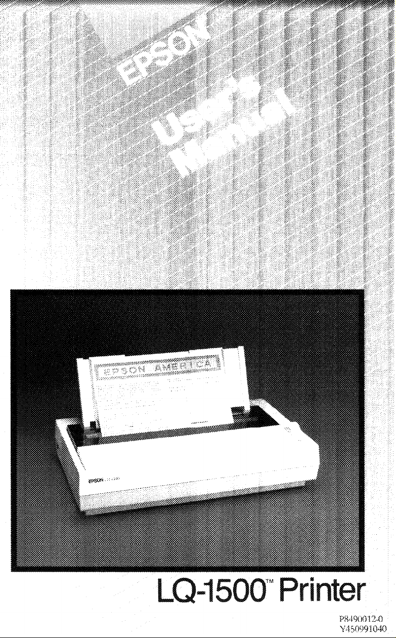
Page 1
Page 2
Page 3

FCC COMPLIANCE STATEMENT
FOR AMERICAN USERS
This equipment generates and uses radio frequency energy and if not installed and used
properly, that is, in strict accordance with the manufacturer’s instructions, may cause
interference to radio and television reception. It has been type tested and found to comply
with the limits for a Class B computing device in accordance with the specifications in
Subpart J of part 15 of FCC Rules, which are designed to provide reasonable protection
against such interference in a residential installation. However, there is no guarantee that
interference will not occur in a particular installation. If this equipment does cause interference to radio or television reception, which can be determined by turning the equipment off and on, the user is encouraged to try to correct the interference by one or more of
the following measures:
- Reorient the receiving antenna
- Relocate the computer with respect to the receiver
- Plug the computer into a different outlet so that the computer and receiver are on
different branch circuits.
If necessary, the user should consult the dealer or an experienced radio/television technician for additional suggestions. The user may find the following booklet prepared by the
Federal Communications Commission helpful:
This booklet is available from the U.S. Government Printing Office, Washington, DC
20402. Stock No. 004-000-00345-4.
All rights reserved. No part of this publication may be reproduced, stored in a retrieval system,
or transmitted, in any form or by any means, mechanical, photocopying, recording or otherwise, without the prior written permission of Epson America, Inc. No patent liability is
assumed with respect to the use of the information contained herein. While every precaution
has been taken in the preparation of this book, Epson America, Inc. assumes no responsibility
for errors or omissions. Neither is any liability assumed for damages resulting from the use of
the information contained herein.
LQ-1500 is a trademark of Epson America, Inc.
“How to Identify and Resolve Radio-TV Interference Problems.”
Copyright © 1984 by Epson America, Inc.
Torrance, California 90505
ii
PB490012
Page 4

Contents
Introduction
LQ-1500 Features
About This Manual
Setting Up
1
Finding a Suitable Location
Getting to Know Your Printer
Installing the paper feed knob
Removing the dust cover
Removing the front cover
Discovering what’s inside
Installing the Ribbon Cartridge
Installing the Sheet Guide
Assembling the three pieces
Attaching the sheet guide
Connecting the LQ-1500 to Your Computer
Locating the interface card
Installing the interface card
Attaching the cable to the printer
Connecting the printer cable
Setting the DIP Switches
Switch1
Switch2
Installing the Power Cord
..................................
..............................
............................
Your LQ-1500
...................................
...................................
.......................
.....................
...................
.....................
.....................
.....................
..................
.......................
...................
.....................
....................
....................
...................
........................
.......................
.................
........
...............
1
1
2
3
3
5
5
7
7
8
9
12
12
12
15
15
17
18
18
19
21
22
24
Operation
2
Controls and Indicators
The power switch
The control panel
The paper-out detector
Maintenance
Cleaning the LQ-1500
Other maintenance
and
..................................
Maintenance
...........................
............................
.....................
.........................
.......................
........................
..........................
25
25
25
25
27
27
27
28
iii
Page 5

Installing Paper and Paper Feeders
3
Types of Paper and Paper Feeders
Single-sheet paper and sheet guide
Pin-feed paper and tractor unit
More Printer Parts
Platen release lever
Print head adjustment lever
Loading Single-Sheet Paper
Preparing the printer for single-sheet feed
Loading single-sheet paper
Removing single-sheet paper
Loading Pin-feed Paper
Installing the tractor unit
Preparing the printer for pin-feed paper
Inserting pin-feed paper
Proper placement of pin-feed paper
Removing pin-feed paper
Removing the tractor unit
The LQ-1500 Self-Test
.............................
..........................
.........................
..........................
................
................
..............
................
...................
.....................
........
....................
..................
.....................
.........
.......................
.............
.....................
.....................
29
29
29
29
30
30
31
31
31
32
34
34
34
35
37
40
41
41
42
Control codes
4
Computer-to-Printer-Communications
How Many Names Can One Code Have?
Appendixes . . . . . . . . . . . . . . . . . . . . . . . . . . . . . . . . . . .
A LQ-1500 Command Summary
Vertical Spacing Commands
Horizontal Spacing Commands
Print Style Commands
Character Set Commands
Graphics Commands
Miscellaneous Commands
Changing Print Styles
B
Proportional Print Styles
Letter Quality Print Styles
Draft Pica Print Styles
Draft Elite Print Styles
.................................
............
...................
.....................
..................
.........................
.......................
...........................
......................
..........................
.......................
......................
..........................
..........................
.........
45
45
46
49
49
50
54
56
61
62
64
69
70
71
72
73
iv
Page 6

C The LQ-1500 Character Set
Regular Characters
International Character sets
............................
.....................
.....................
75
75
78
D
Widths of the Proportional Characters . . . . . . . . . . . .
E
ASCII Code Conversion Chart
F
Specifications of the LQ-1500 . . . . . . . . . . . . . . . . . . . .
. . . . . . . . . . . . . . . . . .
79
87
91
v
Page 7

Figures
1-1
1-2
1-3
1-4
1-5
1-6
1-7
1-8
1-9
1-10
1-11
1-12
1-13
1-14
1-15
1-16
1-17
1-18
1-19
2-1
2-2
Unpacking the LQ-1500
Paperplacement
The LQ-1500 printer
Paper feed knob
Removing the front cover
Printer parts
Ribbon cartridge
Ribbon installation
Ribbon operation
Sheet guide assembly
Paper guide position
Sheet guide installation
Printing single sheets
The dust cover
Interface card
Locating the interface card
Interface card installation
Interface connection to computer
Switch settings
Controls and indicators
Maintenance
...........................
...........................
...............................
...........................
.............................
..............................
.............................
..............................
.....................
........................
....................
.........................
..........................
.......................
........................
......................
........................
...................
....................
.....................
.............
4
5
6
7
8
9
10
11
11
13
14
14
15
16
16
17
19
20
21
26
28
3-1
3-2
3-3
3-4
3-5
3-6
3-7
3-8
3-9
3-10
3-11
D-1
Adjustment levers
Sheetload
Protective cover removed
Tractor unit installation
Printer parts used with pin-feed paper
Paper inserted
Aligning pin frames
Pin-feeder covers
Paper path
Removing the tractor unit
The LQ-1500 self-test
A character and its widths . . . . . . . . . . . . . . . . . . .
................................
................................
..........................
....................
.....................
.........
.............................
.........................
...........................
...................
.......................
30
33
35
36
37
38
39
40
41
42
43
80
vii
Page 8

Tables
1-1 Settings for switch 1
1-2 Settings for switch 2
1-3 International character switch settings
........................
........................
.........
22
23
23
ix
Page 9

Introduction
Congratulations! You’ve purchased the Epson LQ-1500TM. This
advanced, state-of-the-art printer combines the quality of typewriter
print with the speed of a dot matrix printer. Of course, it has all the
capabilities of the other Epson printers-and more too.
LQ-1500 Features
The LQ-1500 is designed to be used day in and day out in an office
environment. Its size and rugged good looks proclaim this fact. Its
Epson engineering guarantees it.
The LQ-1500 has a long list of features. Just a few of the highlights
include:
l
Letter quality printing. The LQ-1500’s 24-pin print head can print
letter quality characters in four widths.
l
Proportional letter quality printing. The LQ-1500 can print in two
widths of proportional letter quality characters.
l
Draft speed. The LQ-1500 can print at 200 characters per second
using the draft character set.
l
Two hundred and twenty-four printing styles. The LQ-1500 can
print in 224 different printing styles, not counting superscripts and
subscripts.
l
Upward compatibility. The LQ-1500 includes all of the major fea-
tures of the FX series of printers.
l
Userdefined characters. The LQ-1500 allows you to design your
own character sets, in either draft or letter quality mode.
1
Page 10

l
2
High-resolution graphics. The LQ-1500 has all the graphics capabi-
lities of the FX series of printers and more. The 24-pin print head
provides top-quality, high-resolution graphics.
l
Text buffer. The LQ-1500 has a 2048 character text buffer to increase
printing speed. The buffer takes information quickly from your
computer, leaving the computer free for other tasks while the
LQ-1500 finishes printing.
About This Manual
The LQ-1500 is a sophisticated machine. Although it is simple to
operate, writing programs for it can be complicated. In many cases,
the people who use the LQ-1500 are not the ones who do the programming. Therefore, Epson has provided two different manuals. This
LQ-1500 User’s Manual contains all the information required to set up
and operate, the LQ-1500. The LQ-1500 Programmer’s Manual contains the information required to write programs for the LQ-1500.
Epson also supplies Application Notes that tell you how to use the
LQ-1500 with specific software programs.
The first three chapters of this manual will help you set up, operate
and maintain your printer. Chapter 4 contains information on how to
use control codes with your printer.
The appendixes contain helpful information about selecting print
styles and character sets, and about using control codes to command
certain printer functions. Appendix A summarizes the control codes.
Appendix B explains how to change from one print style to another
and shows examples of different print styles. Appendix C shows the
character sets available on the LQ-1500, including the regular and
international sets. Appendix D gives the dot width of each of the
available proportional characters. Finally, Appendix E, a convenient
conversion chart, provides all the possible names for each ASCII
code.
This user’s manual is not long, but it contains a lot of important
information. In spite of its simple design, the LQ-1500 is a precision
printer, and you should know the right way to assemble and take care
of it. Reading this manual will help assure you of success when you
begin to use the LQ-1500.
Page 11

Chapter
1
Setting Up Your LQ-1500
You’ve just purchased a terrific new printer, and dug far enough into
the box to find this manual. Now what? In this chapter we’ll show you
how to set up your
First, take inventory. Carefully unpack the carton and make sure
that you have all of the pieces shown in Figure
l
LQ-1500 printer
l
Sheet guide (three pieces)
l
Dust cover
l
Front cover (installed on the printer)
l
Paper feed knob
l
Power cord
l
Ribbon cartridge
l
This User’s Manual.
LQ-1500
and connect it to your computer.
1-1:
Note: It’s a good idea to save all of the packing materials in case you
want to move your LQ-1500 some day.
Finding a Suitable Location
Before you actually set up your printer, you should give some
thought to where you are going to put it. Of course, your printer must
sit somewhere near your computer (the length of the printer cable is
the limiting factor). However, you may not want to place your com-
puter and printer side by side because the printer does make noise
3
Page 12
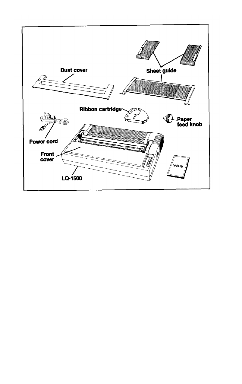
Fig-we 1-1. Unpacking the LQ-1500
during operation. Here are some additional suggestions to follow:
1.
Place the LQ-1500 on a flat, stable surface. The printer will make
more noise if you place it on a table that moves or vibrates.
2. Connect the printer to a grounded electrical outlet (do not use an
adapter plug). It’s a good idea to choose an outlet which is not
controlled by a wall switch that could be accidentally shut off dur-
ing the printing process.
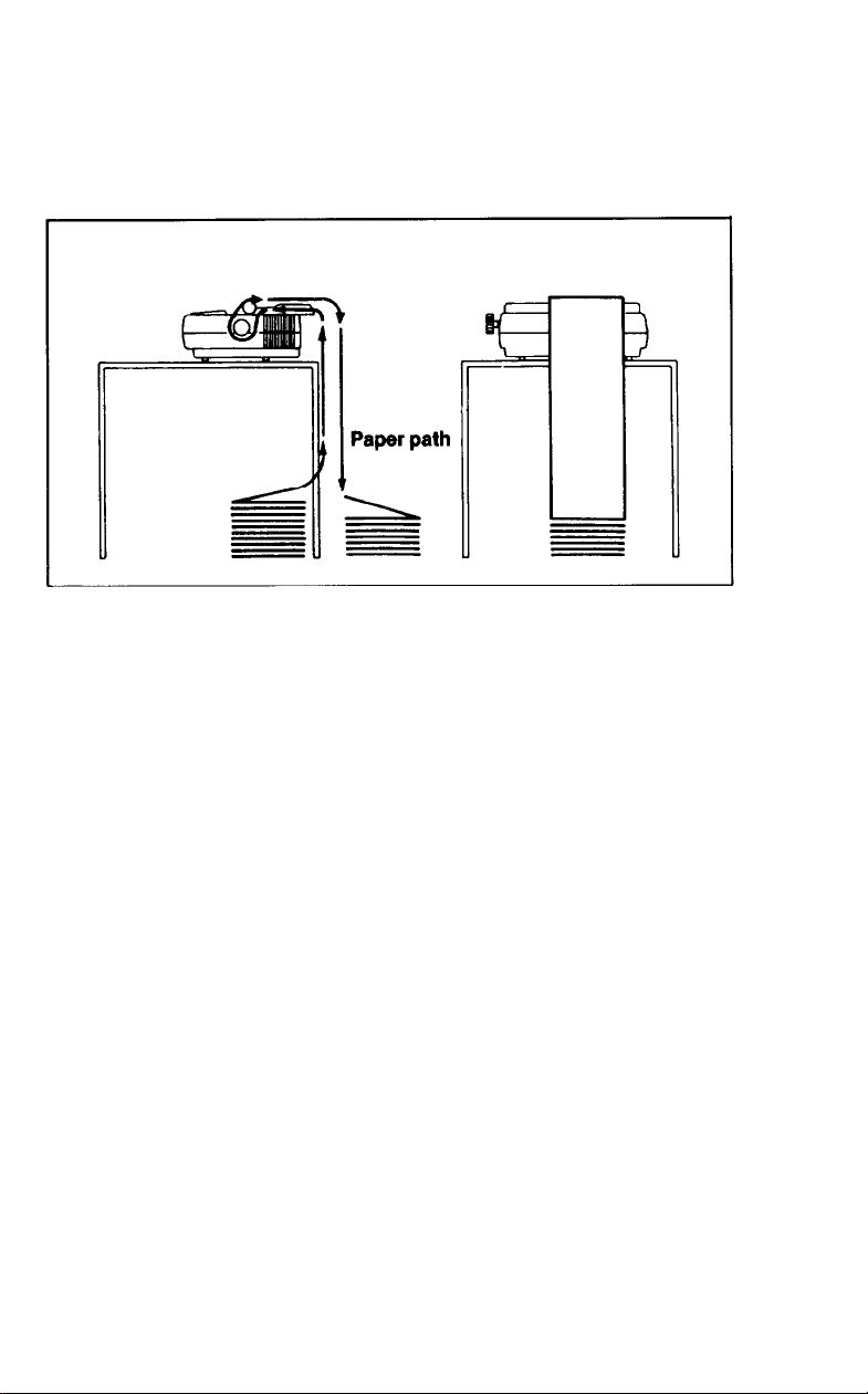
3. Choose a location which will allow enough space beneath or
behind the printer to load the paper. If you are using continuous (or
pin-feed) paper, the paper path should be free from obstruction
(see Figure
4. Protect the printer from prolonged exposure to direct sunlight,
moisture, and dust. Make sure that it is not close to a heater or any
other heat source.
1-2).
4
Page 13
5. Use the LQ-1500 in areas that are comfortable for you. If you find
5
it too hot, too cold, or too humid, the environment is not right for
the LQ-1500; it may not operate properly.
Figure 1-2. Paper placement
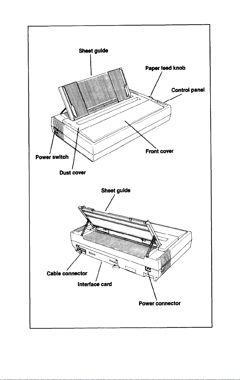
Getting to Know Your Printer
Now you’ve got a small collection of odd-shaped pieces placed in a
suitable location. The next step is to put them all together to form a
functional printer. Figure 1-3 shows the assembled printer and identifies some of the main parts.
WARNING: To avoid shock hazard and prevent damage to the
LQ-1500,
described here with the power to the printer turned OFF.
Installing
The first piece to install is
manually turn the platen and advance the paper-just as you do on a
typewriter. To install the paper feed knob, simply push it onto the
shaft on the right side of the printer. This is shown in Figure 1-4.
the paper feed knob
complete all of the installation procedures
the
paper feed knob, which you use to
Page 14
6
Figure 1-3.
The LQ-1500 printer
Page 15
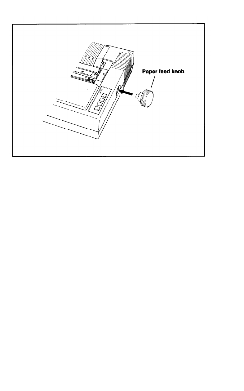
Figure 1-4. Paper feed knob
Removing the dust cover
The dust cover is the brown plastic cover which keeps dust out of
the print mechanism and reduces the noise level when the printer is
on. If you are using
cover.
Lift off the dust cover. It just sits in a recess on the top of the printer
so removal is easy Set the dust cover aside if you will be needing it.
Put it away in
unit.
the
optional tractor unit, you will not use the dust
the
printer box if you plan to use
the
optional tractor
Removing the front cover
The next assembly step, installing the ribbon cartridge, first
requires a bit of disassembly. You should remove the front cover to
gain easier access to the print head when you install the ribbon.
Open the front cover by tilting the back edge up and toward you.
Push left and up. Gently lift off the cover and set it aside (see Figure
1-5).
You’ll see it’s easier to do than it is to describe!
7
Page 16
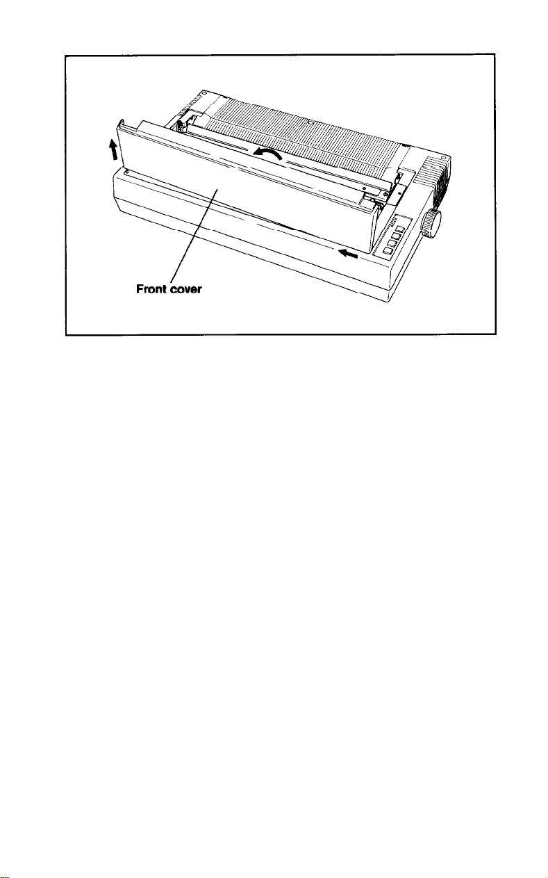
Figure 1-5. Removing the front cover
Discovering what’s inside
Now that you can see the insides of the printer, take a few moments
to find some of the parts that you need to know about. Study Figure
1-6
until you can identify these parts:
The print head is probably the easiest part to locate, so start with it.
The print head is the large, black, finned object that moves back and
forth on two silver rods across the printer.
The ribbon guide is the silver shield on the side of the print head
next to the paper. The ribbon guide guides the ribbon between the
print head and the paper.
The paper is guided through the printer by a large rubber roller
called the platen. It has the same function as the platen in a typewriter.
The paper bail is the numbered scale with three black rollers on it.
The paper bail rests against the platen and holds the paper in place as it
moves through the printer.
8
Page 17
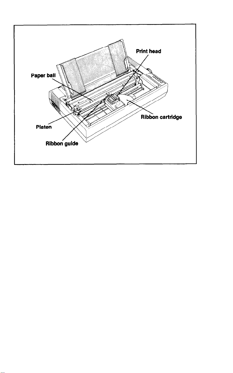
Figure 1-6. Printer parts
Once you identify these parts, you will know enough about the
printer to get started. This manual will help you identify other parts as
the need arises.
Installing the Ribbon Cartridge
The LQ-1500’s ribbon cartridge is easy to install, and it won’t get
your hands dirty. Follow these steps for a quick installation.
1.
Close the paper bail so that it is against the platen.
2.
Grasp the print head by the finned part and slide it along the silver
rods until it is positioned at
space on either side of the print head when you insert the ribbon
cartridge.
3.
Rotate the ribbon cartridge take-up knob in the direction indicated
by the arrow next to it so that the ribbon is tight (see Figure
Don’t worry about wasting the ribbon by turning too much; the
ribbon is a continuous loop inside the ribbon cartridge.
40
on the paper bail scale. You will need
1-7).
9
Page 18
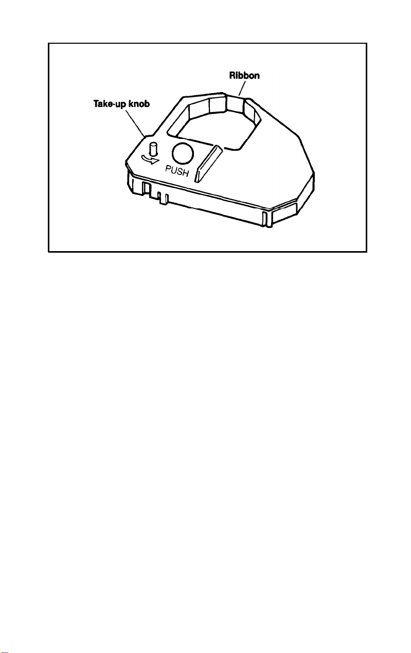
Figure 1-7. Ribbon cartridge
4.
Hold the ribbon cartridge in both hands to position it over the print
head (the hole in the ribbon cartridge fits over the finned part of the
print head). The short piece of exposed ribbon must go between
the print head and the ribbon guide so that the ribbon does not rest
directly against the platen (see Figure
tridge and press the spot marked PUSH to seat the back of the
ribbon cartridge first.
5. Once you have positioned the exposed ribbon and secured the
back end of the ribbon cartridge, push down on the front of the
cartridge to snap it into place. The ribbon cartridge will sit level
when it is positioned correctly.
1-8).
Lower the ribbon car-
6. Now
give the take-up knob several turns to straighten out the ribbon so that it is not wrinkled or twisted. The ribbon should move
freely between the print head and the ribbon guide (Figure 1-9).
10
Page 19
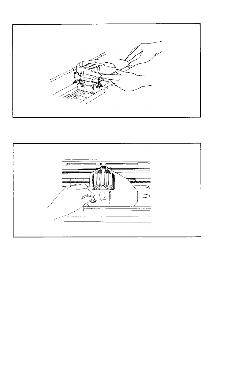
Figure 1-8. Ribbon installation
Figure
To replace the front cover, simply reverse the steps you took to
remove it. Fit
until it is securely in place. Tilt the cover back into the closed position.
It should fit snugly.
the
right end into place first and then lower the left end
1-9. Ribbon operation
11
Page 20

Installing the Sheet Guide
The sheet guide serves a dual purpose on the LQ-1500. If you are
using single sheets of paper, the guide ensures consistent margins and
straight lines of print. If you are using pin-feed paper, the sheet guide is
used as a paper separator to keep the incoming and outgoing paper
from interfering with each other.
Assembling the three pieces
First, you must assemble the three pieces of the sheet guide.
1. Orient the sheet guide so that the textured side is up and the metal
mounting pins are facing you. Lay one of the two sliding paper
guides on top of the sheet guide. The matching textured side should
be facing up and the lipped end should be facing toward you. Now
tilt the top of the sheet guide up so that you can hook the tabs at the
top of the sliding paper guide over the top edge of the sheet guide
(see Figure 1-10).
2.Next,
your thumbs to snap the the two plastic spring clips over the bottom edge of the sheet guide. One of the sliding paper guides should
now be securely in place.
3.Again,
you. Move the installed sliding guide to the proper end of the sheet
guide. The vertical standing edge of the sliding paper guide should
be flush against the outer edge of the sheet guide. The flattened side
of the sliding guide faces toward the center.
4.
To install the other paper guide, just repeat the steps above. Be sure
to attach the second sliding guide with the vertical standing edge
facing out toward the end of the sheet guide and away from the
center (see Figure
turn the sheet guide over so the back side is facing you. Use
position the sheet guide so that the textured side is facing
1-11).
Attaching the sheet guide
To install the sheet guide, place the metal mounting pin on the right
side of the sheet guide into the corresponding hole in the metal frame.
Then lower the left side until the tab on the left side drops into the slot
in the metal frame. Figure
1-12
shows how to do this.
12
Page 21
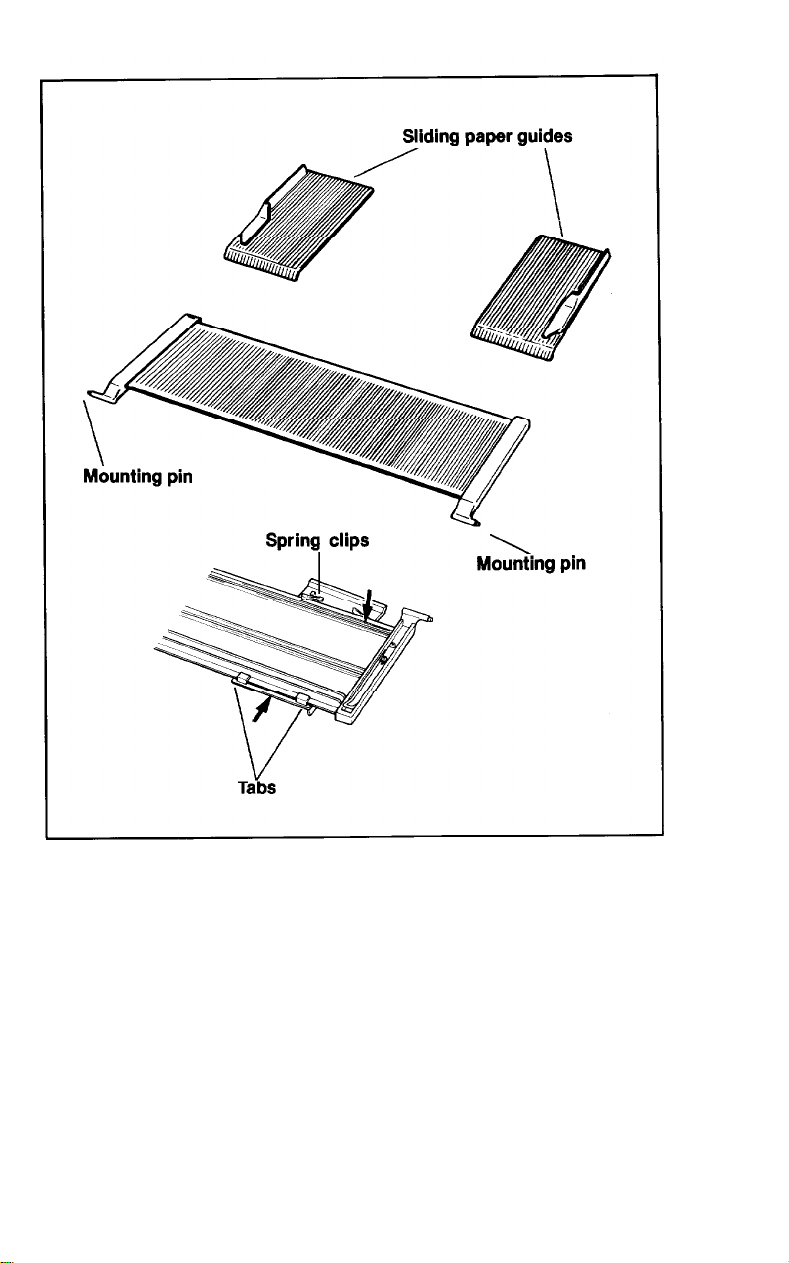
Figure 1-10. Sheet guide assembly
13
Page 22
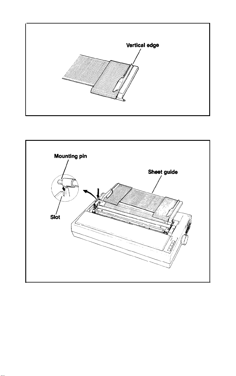
Figure 1-11. Paper guide position
Figure 1-12. Sheet guide installation
If you plan to use your LQ-1500 with single sheets of paper, lift up
the
sheet guide at the back and fold down the metal legs on the bottom
of the sheet guide. As shown in Figure 1-13, the legs fit into slots in the
top case of the LQ-1500. (This step is not necessary if you will be using
the
optional tractor unit.)
14
Page 23
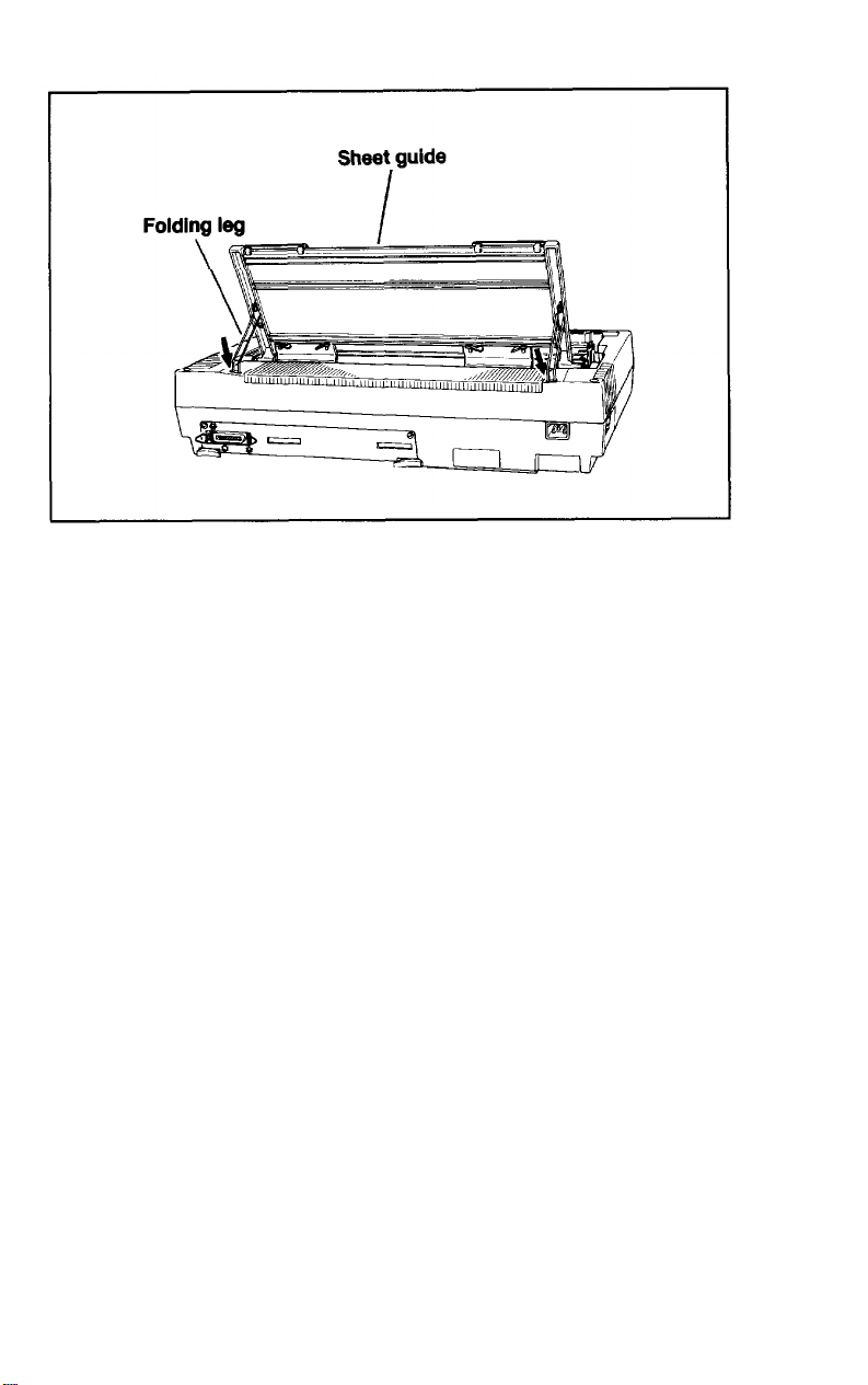
Figure 1-13. Printing single sheets
Once the sheet guide is installed you can replace the dust cover on
top, as shown in Figure
tective film that is on the switch panel at the right front of the
LQ-1500.
shipment and can be easily peeled off.
This film protects the switch panel during manufacture and
1-14.
Also, you may want to remove the pro-
Connecting the LQ-1500 to Your Computer
Your printer setup is now almost complete. The next step will be to
connect your printer to your computer. At the printer end of this connection, two additional pieces of equipment are required: an interface
card and a printer cable. The interface card consists of a circuit board
pre-mounted into a metal carrier (Figure
Locating the interface card
Epson makes three types of interface cards for the LQ-1500: para1lel, serial, and IEEE 488. With the use of easily interchangeable interface cards, this powerful printer can be driven by nearly any
computer or word processor. Your Epson dealer can advise you about
which interface is best for your computer and application.
1-15).
15
Page 24
Figure 1-14. The dust cover
Figure 1-15. Interface card
16
Page 25
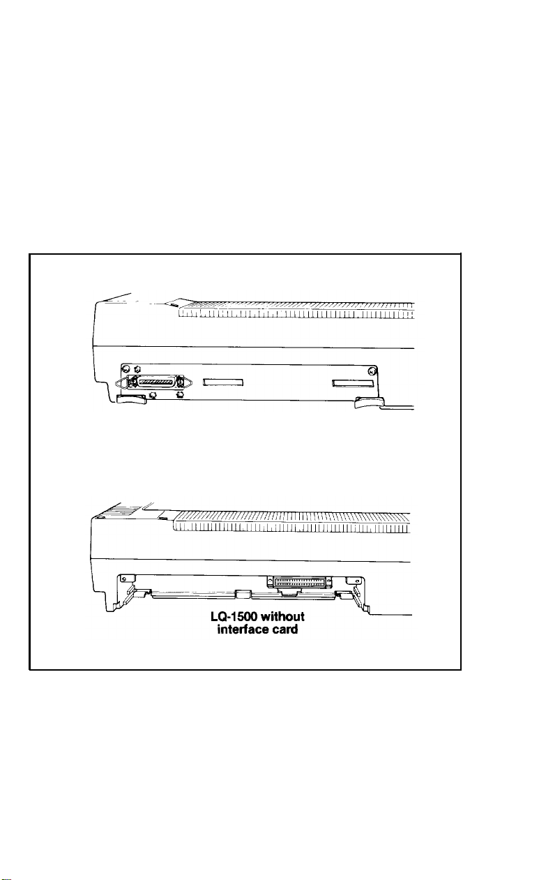
Installing the interface card
Your dealer may have already installed the interface card for you.
Turn your printer around and look at the back of the printer to tell if
the interface card has been installed (see Figure
cavity at the lower left, the interface card is missing and you must
install it before you can use your LQ-1500. If, on the other hand, there
is a plug connector at the lower left, the interface card has been
installed for you. (If your interface card has been installed, you can
skip to the next section.)
LQ-1500 with interface
card installed
1-16).
If there is a large
Figure 1-16. Locating the interface card
17
Page 26

The installation procedure is the same for all three of the available
interface cards. The card is easily mounted or removed. The only tool
you need is a Phillips screwdriver.
To install the interface card slide it into the cavity on the back of the
LQ-1500 as shown in Figure 1-17. It should slide between the upper
and lower plastic guide rails on either side of the opening.
When you feel resistance on the right side of the card, firmly push it
in with both hands. It may help to push against the card release levers
to snap the card into place. The interface card should be flush and
even with the back of the printer; it should not tilt or protrude.
Now, lift up slightly on the card and secure it in place with the
screws provided.
If you use your LQ-1500 with different computers, you may have to
remove and replace this card. Begin by removing the retaining screws.
Then pull the release levers on both sides of the interface card at the
same time. The card will slide out easily.
Attaching the cable to the printer
Note: Before you connect any cables, be sure that both the printer
and the computer are turned OFF.
One end of your printer cable should plug right into the connector
on the interface card (if it doesn’t, you have the wrong cable). To
secure the connection, attach the two clips on the interface card to the
cable (parallel interface only) or tighten the two screws on the cable
connecter (serial and IEEE 488 interfaces). If your cable has a ground
strap, connect it to the screw just above the interface connector. Figure
1-18 shows both types of connections.
Connecting the printer cable
For many computers, you merely plug the cable into the printer
port on your computer. Some computers require a printer interface
card, either mounted inside the computer or externally. Check your
computer installation and operations manual for details on how to
connect your computer to a printer.
18
Page 27
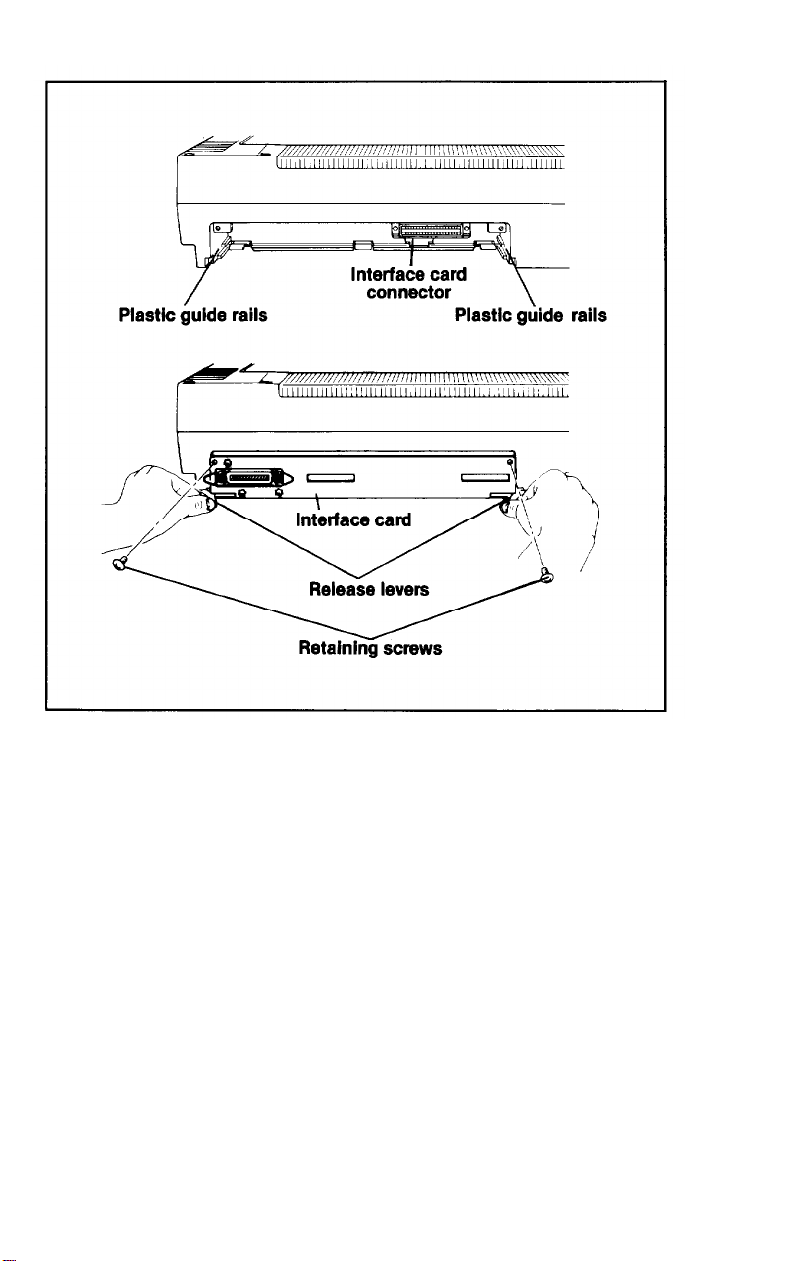
Figure 1-17. Interface card installation
Setting the DIP Switches
This is the last step in installing your printer. Because each com-
puter installation is slightly different, Epson has placed a series of DIP
switches on the back of theprinter interface, which you can change to
best suit your printing application. You can see them through a slot in
the back cover of the interface card.
19
Page 28
Figure 1-18. Interface connection to computer
WARNING: The DIP switches we are discussing are in the interface
unit on the back of the printer. Do not change the set-
tings of the DIP switches that are inside the printer.
These settings have been determined by the manufacturer to be correct for this LQ-1500 printer. Special
knowledge is required to set these switches.
You can use a ballpoint pen to reach into the interface slot and change
switch settings.
Note: Be sure that the printer is turned OFF before you make any changes
in the DIP switch settings. Your printer does not register changes in
switch settings made while the power is ON. You must reinitialize,
or restart, the printer to record the switch settings.
The switches are all numbered for identification. The number has
two parts. The first part refers to the switch group. Look at the back of
your printer; you will see one group of four and one group of eight
switches. You can identify the switch groups by looking at Figure
As you can see, each switch group is actually a series of switches.
That’s the reason that each switch is referred to by two numbers. The
1-19.
20
Page 29
second digit refers to the individual switch number. It is printed right
on the switch itself.
You can also see that there is a small arrow on the left side of the
switch group which indicates the ON position for these switches.
However, it’s easier to remember switch settings according to whether
the switch is pointing up (toward the top of the printer) or down
(toward the bottom of the printer).
Interface
Switch 1
Switch 2
Figure 1-19. Switch settings
Switch1
The functions of the four switches that make up switch 1 are sum-
marized in Table
1-1.
The right-hand column shows how the switches
are set when the printer is delivered. These predetermined settings are
best for most applications.
21
Page 30

Table 1-1. Settings for switch 1
Switch
1-1
1-2
1-3
1-4
Function
2K byte input buffer
Paper-out detector
Automatic line feed
Reserved for future use
Up
Disable
Disable
On
Always down
Switch 1-1--In the down position, this switch
buffer of
want to print a document at the same time you continue to use your
2048
bytes
of memory.
This
buffer can be useful when you
Down
Enable
Enable Down
Off
allows
Factory
Down
Down
Down
you to create a
computer for other tasks.
WARNING:
If you turn
OFF
the LQ-1500, any information in the
buffer is lost.
Switch 1-2--Switch 1-2 enables a detector in the LQ-1500 that warns
you when the printer is out of paper. This is very important when you
are using continuous paper. The printer stops, issues an audible warn-
ing, and waits for you to load more paper before proceeding-and no
data is lost.
However, if you are using single sheets, the paper-out detector stops
the printer when it nears the bottom of the sheet (even if you want to
print all the way to the bottom or if you have another sheet ready to
feed). In this case, it is best to disable the paper-out detector by turning
switch
1-2
to the Up position. With the printer’s paper-out detector
disabled, the application software in your computer must determine
when it has come to the end of a page. Check with your software
dealer if you have difficulty.
Switch 1-3--Switch 1-3 controls whether or not the LQ-1500 does an
automatic line feed each time it receives a carriage return. Some computers do not send line feeds to the printer which means that this
switch must be up.
Switch 2
Switch 2 determines which print characteristics will be in use when
the
LQ-1500
is turned on. Each of these functions can be changed at
22
Page 31

any time by sending the appropriate command to the printer. The
functions of the individual switches are summarized in Table 1-2.
Switch
2-1
2-2
2-3
2-4
2-5
2-6
2-7
2-8
Table 1-2. Settings
Function
International character sets (see Table 1-3)
Form length
Skip over perforation
Bell
Print mode
SLCT IN signal
for
switch 2
Up
12 in.
On
Disable
Letter quality Draft
Fixed
Down
11 in.
Off
Enable
Not fixed Up
Factory
UP
UP
Up
Down
Down
Down
Down
Switches 2-1, 2-2, and 2-3--These switches are used to determine the
default international character set. Appendix C shows the characters
that are included in each of the character sets. Table 1-3 shows the
required switch settings for each set.
Table 1-3. International character set switch settings
2-1
UP
UP
UP
Up
Down
Down
Down
Down
2-2
UP
UP
Down
Down
UP
UP
Down
Down
2-3
UP
Down
UP
Down
UP
Down
UP
Down
International character set
U.S.A.
France
Germany
United Kingdom
Denmark
Sweden
Italy
Spain
Switch 2-4.--Switch
2-4
is used to tell the LQ-1500 the size of paper
that you will be using. It uses this information to keep track of the
perforation and the top of the form.
Switch 2-5--The LQ-1500 automatically leaves a top and bottom
margin of 1/2 inch on each page if switch 2-5 is in the up position. The
switch tells the printer to skip over each perforation so that nothing is
printed on top of the perforation. This is especially useful for printing
long program listings. Many word processing programs, however,
23
Page 32

have commands for setting top and bottom margins and they work
best if the skip-over-perforation feature is turned off.
Switch 2-6--There are occasions when the printer bell (which is actually a buzzer) can be used to signal the operator. For example, you
may want to switch paper in the middle of a long document. You can
use the bell to signal when it is time to make the change, To make use
of this feature, leave switch 2-6 down in the down position. For a
rough draft, it may not be necessary to switch paper, so by turning
switch 2-6 up, you won’t be bothered by unnecessary noise. Gener-
ally, switch 2-6 is left in the down position.
Switch 2-7--This switch also selects a feature that you may want to
use one way for rough drafts and another way for the final printout.
You can select either letter quality printing or draft printing. The
LQ-1500 prints much faster in draft mode, but the quality isn’t as
good. You can also change between draft and letter quality printing by
using commands sent from your computer.
Switch 2-8--This switch is used to control the select signal. Most com-
puters require that the select signal be fixed (switch is in the up posi-
tion). If your computer requires that the select signal not be fixed, then
set the switch in the down position.
If you have a parallel interface card, your installation is now complete! Go on to Chapter 2, where you’ll learn how to operate the
LQ-1500.
If, on the other hand, you have a serial or IEEE 488 interface card,
you have a few more switches to set in order to ensure that your computer and LQ-1500 are communicating properly. Consult your interface user manual for instructions on the proper setting of these
switches.
Installing the Power Cord
If you have been following along so far you should have one piece
left: the power cord. Plug one end into the LQ-1500--the connection
is on the rear of the printer near the right side (as you face the rear).
Plug the other end into a standard (120 VAC, 60 Hz) grounded electrical outlet (do not use an adapter plug).
24
Page 33

Chapter 2
Operation and Maintenance
Your
LQ-1500
and set the switches. Now you’re ready to learn how to use the controls and indicators on the printer to operate it correctly. We’ll also
give you some advice on how to maintain your LQ-1500 and keep it
printing smoothly for a long time.
is now set up. You’ve connected it to your computer
Then, in Chapter
feeders which will give you an opportunity to use the controls discussed here.
3,
you’ll learn how to install and load the paper
Controls and Indicators
There are several controls and indicators on the LQ-1500 (see Figure
2-1). You use them to operate the printer and make your day-to-day
printing easier for you. Here’s what these controls do:
The power switch
The power switch is located on the left side (toward the rear) of the
printer. Press the front side of the switch to turn the printer ON; press
the back side to turn it OFF.
The control panel
The control panel, located on top of the computer, has indicator
lights and buttons which monitor the printing process. They are:
l
POWER light -- glows green when the power is ON.
• READY light -- glows green when the printer is ready to accept
data. The light flickers somewhat during transmission. This flick-
ering is normal.
25
Page 34

Power switch
Figure 2-1. Controls and indicators
l
PAPER OUT light -- glows red when the printer is out of paper;
printer will stop printing (if Switch 1-2 is in the up position).
l
ON LINE light -- glows green when data reception is possible.
l
ON LINE button -- allows you to switch from on-line to
off-line
status (this is a toggle). When the printer is on line, it is ready to
accept data from the computer and the ON LINE light glows green.
When the printer is off line, it is not ready to print.
When the printer is off line, you can use the form feed (FF) and line
feed (LF) buttons on the control panel to move the paper. The ON
LINE and READY lights will be off. You can return the printer to
on-line operation at any time, just by pressing the ON LINE button.
l
FF button -- stands for
form feed.
When you’re off line, pressing
this button will advance the paper to the top of a new page.
26
Page 35

l
LF button -- stands for
line
feed. When you’re off line, tapping this
button advances the paper one line at a time. To advance multiple
lines, hold down the LF button. Do not perform continuous line
feeds for more than two minutes.
l
SHEET LOAD button -- opens the paper bail and loads single-
sheet paper into the printer.
The paper-out detector
The printer is equipped with a device which warns you that the
printer is out of paper. When your paper runs out, printing stops, the
PAPER OUT light goes on, and the printer buzzer sounds five times.
When you have loaded more paper, the PAPER OUT light goes off.
Printing can be resumed in one of two ways. If you are in the middle
of printing, press the ON LINE button. If you want to reinitialize the
printer, turn the power switch OFF and then back ON.
You can turn off the paper-out detector in two ways: by DIP switch
1-2 on the interface card, or by a control code sent from the computer.
Turning off the paper-out detector tells the printer to ignore the paperout sensor and allows you to print to the bottom of the page. Some
computers will stop the printer before the end of the page, even
though DIP switch 1-2 is down (off). If this happens, you may need to
consult your dealer about the interface between your computer and
printer. You may also consult your software dealer for further information.
Maintenance
As with any mechanical device, the best maintenance of your
LQ-1500 is preventive maintenance. You’ve already started by choosing a clean, dust-free location with a comfortable temperature range.
Of course, you will change your ribbon cartridge whenever it loses
quality through use.
In addition, your printer requires periodic cleaning. Here are a few
tips on how to perform this maintenance properly.
Cleaning the
You should clean the outside of the printer case whenever it appears
to be dirty. Use a clean damp rag and alcohol. Be careful not to drip
alcohol on the printer mechanism.
LQ-1500
27
Page 36

You should also clean the inside front portion of the printer (Figure
2-2) to get rid of dust and paper lint. To do this, turn the power switch
off and disconnect the power cord. Remove the dust cover, the front
cover, and the ribbon cartridge. Use a small vaccum cleaner and a soft
brush to clean inside the printer. Be careful not to bend or damage any
of the parts inside the printer. With the power off, you can easily move
the print head back and forth to clean under it. Use as light a touch as
possible to get the job done.
Figure 2-2. Maintenance
Other maintenance
Changing the ribbon cartridge and cleaning
maintenance tasks that you should do. There are no user-serviceable
parts inside the LQ-1500. Leave any other types of maintenance
(fuses, print heads, etc.) for your Epson dealer or authorized service
center. The LQ-1500’s print head is not user-replaceable because it
must be carefully aligned with special tools to achieve the best printing
quality
28
the
printer are the only
Page 37

Chapter 3
Installing Paper and Paper Feeders
Now that you are more familiar with your LQ-1500, you’re ready
to install and load the paper feeders. Since you’re into the third chapter, you’re probably getting anxious to print something by now. First,
you need some facts on the different types of paper and paper feeders
the LQ-1500 uses.
Types of Paper and Paper Feeders
You can use a great variety of paper types with the LQ-1500 which
makes your printing both flexible and convenient. Paper thickness can
range from 0.07 mm to 0.20 mm for both types of paper feeders.
Single-sheet paper and sheet guide
First, you can use single-sheet paper including all the standard sizes
of stationery and preprinted business forms. Single-sheet paper may
vary in width from 7.2 to 14.3 inches. The sheet guide unit is used to
feed single-sheet paper into the LQ-1500. As you may recall, Chapter
1 gave you the details for installing the sheet guide unit.
Pin-feed paper and tractor unit
Second, you can use pin-feed paper (also called continuous-feed
paper). This includes the familiar fan-fold paper with pin-holes on
either side, pin-feed labels, and other types of continuous forms. The
LQ-1500 will handle pin-feed paper from 4 to 16 inches wide. Pin-feed
paper is used with an optional tractor unit which pulls the paper
through the printer by the pin holes.
29
Page 38

More Printer Parts
You also need to become familiar with two other important printer
parts before you attempt to load any type of paper. Remove the dust
cover and open the front cover to find and identify these parts: the
platen release lever and the print head adjustment lever.
Platen release lever
The platen release lever controls the pressure of the friction rollers
against the platen. It is the black lever located on the left side of the
printer at the end of the platen (as shown in Figure
two settings: engaged (back) and released (forward).
3-1).
This lever has
Figure 3-1. Adjustment levers
The first setting, engaged, is used with the single-sheet feed operation which is also called friction feed. In this position the pressure of
the friction rollers against the paper causes it to feed through the
printer.
30
Page 39

The second setting, released, is used when the tractor unit is in
place. The platen release lever is pulled forward toward the front of
the printer. In this position, the friction rollers do not catch the paper
but allow it to move freely through the paper path. The tractor unit is
installed above the platen and draws the paper through by its pin
holes.
Print head adjustment lever
The space between the print head and the platen should be adjusted
to accommodate the thickness of the paper you’re using. Thicker
paper needs a wider space to allow for clean printing and smooth
paper movement. Open the front cover of your printer. You’ll find
that the print head adjustment lever is a small black-tipped lever
located on the left side of the printer in front of the platen release lever
(as shown in Figure
The print head adjustment lever has five positions to widen or narrow the space between the print head and the platen. Move the lever
back (toward the rear of the printer) to decrease the space and forward
(toward the front of the printer) to increase the space. Most paper of
standard thickness should be accommodated with the lever in the
straight-up position.
3-1).
Loading Single-Sheet Paper
Printing on single-sheet paper is fast and easy with the LQ-1500.
The printer does most of the work and does it the same way every
time. Your main responsibility is to set each sheet of paper in the sheet
guide unit evenly and press the correct button. We’re sure you’ll agree
this method is much easier than setting up your paper manually each
time you insert a new sheet.
Preparing the printer for single-sheet feed
The following steps tell you how to prepare the printer for single-
sheet feed.
1.
Remove the dust cover and front cover. Remove the tractor unit if
it is installed.
31
Page 40

2.
Install the sheet guide unit and place it in the upright position (see
Chapter 1 for details). Line up the left edge of the left sliding guide
with the 1 on the paper bail. This is very important because paper
near the center or the right side of the platen will not be detected by
the printer.
3. Be sure that switch 1-2 is in the up position to disable the paper-out
detector. This allows the printer to print to the end of the page.
Remember that your computer is now responsible for stopping the
printer when it reaches the end of the paper.
4. Close the paper bail so that it rests against the platen.
5. Engage the platen release lever by pushing it toward the rear of the
printer.
6.
Set the print head adjustment lever for the paper you are using.
Remember that upright is the right adjustment for most paper.
7. Replace the front cover and dust cover.
Loading single-sheet paper
Now that you have prepared the printer, you can load the paper
into the sheet guide unit. Remember to load one sheet at a time.
Follow the steps outlined below and refer to Figure
single-sheet paper into the printer.
1.Place
paper guide on the right to the width of the paper. The paper
should be square in the guide. Tap the top of the paper gently to
work it down into the printer.
2. If the printer is OFF, turn it ON. The PAPER OUT light should be
off. If it is on, then the paper is not down in the printer far enough
or it is not far enough to the left side of the platen.
3.Press
Both the READY and ON LINE lights are off.
4. Press the SHEET LOAD button. The paper will begin to automati-
cally feed into the printer and the paper bail will open. After the
paper has been loaded, the paper bail will automatically close.
a single sheet of paper in the sheet guide unit and adjust the
the ON LINE button to put the printer into off-line mode.
3-2
to load
32
Page 41

Paper
Figure 3-2. Sheet load
Note:
If the paper does not advance far enough to be held by the paper
bail, turn OFF the power, remove the dust cover, open the paper
bail, and use the paper feed knob to advance the paper to the
proper position. This problem is caused by not having the paper
far enough down in the printer when you press the SHEET
LOAD button. You may damage your printer parts if you do
this repeatedly with the power ON.
If the paper is not straight in the printer, press the FF (FORM FEED)
button; the paper feeds the rest of the way through the printer.
Remove the paper and place it back in the sheet guide unit. Repeat
step 4 to reload the paper.
WARNING: Do not move the paper backward through the printer
because it may damage the paper-out detector.
5. Return the printer to the on-line mode by pressing the ON LINE
button. The ON LINE and READY lights should now be on.
You are now ready to print! Repeat the steps above to print more
single pages.
33
Page 42

Removing single-sheet paper
To remove single-sheet paper from the printer, set the printer in the
off-line mode by pressing the ON LINE button (remember its’s a tog-
gle). The ON LINE and READY lights should now be off. Press the FF
(FORM FEED) button and the paper will be ejected from the printer.
Loading Pin-feed Paper
Pin-feed paper is used quite frequently. It is convenient if you do
lots of printing or want to use special pin-feed forms such as labels. It
is also very convenient for printing rough drafts of documents where
you can use less expensive paper.
Loading the LQ-1500 with pin-feed paper is not difficult, but it does
require that you have the optional tractor unit purchased separately
from your dealer. As with single-sheet feed, the printer does most of
the work and virtually takes care of itself until the paper runs out. All
you have to do is load the paper correctly.
Installing the tractor unit
The following steps show you how to prepare the printer for pinfeed paper (see Figures 3-3 and 3-4).
1. Turn OFF the printer. Remove the dust cover and the front cover.
2. If the sheet guide unit is installed, lay it back flat against the top of
the printer. It should not remain in the upright position when you
install the tractor unit.
3. Remove the small protective cover on the right side of the printer
to make room for the tractor unit. It is retained by a single Phillips
screw as shown in Figure 3-3. Put the piece away in a safe place.
4.
Locate the metal brackets on either side of the printer. These brackets have two functions: they hold the sheet guide unit and the tractor unit. Notice that there are two unused wedge-shaped slots
which will hold the tractor unit. Pick up the tractor unit by each
end and slip the tiny silver pegs into the open slots (see Figure 3-4).
34
Page 43

Figure 3-3. Protective cover removed
5. Gently tilt the tractor unit toward you and push the tractor unit
down until you feel it lock into place.
Preparing the printer for pin-feed paper
With the tractor unit now installed, you can prepare the printer to
load the pin-feed paper. Follow the steps outlined below and refer to
Figure 3-5.
1. Set DIP switch
detector. This allows the printer to stop printing and signal when
you are out of pin-feed paper.
2.Open
3. Unlock the gray pin-feeder lock levers on the tractor unit by pull-
the paper bail by pulling it forward (toward the front of the
printer).
ing them toward the front of the printer and slide both pin-feeders
outward to the sides. Open the black covers on the pin-feeders.
1-2
in the down position to enable the paper-out
35
Page 44

36
Figure 3-4. Tractor
unit installation
Page 45

Figure 3-5. Printer parts used with pin-feed paper
4.
Set the paper support skids evenly from the approximate center of
the paper width (as shown in Figure 3-6). This helps the paper feed
smoothly.
Note: If you are using narrow or standard width paper, you must
insert it at the far left of the platen (just as you did with singlesheet paper).
5. Make sure the platen release lever is closed (back).
Inserting pin-feed paper
Now that you have prepared the printer, you can load the pin-feed
paper by following these steps:
1. Make sure you have a clean top edge. Insert the pin-feed paper into
the paper guide slit at the rear of the platen as shown in Figure 3-6.
(If the sheet guide unit is installed, slide the paper underneath it.)
37
Page 46

Advance the paper by turning the paper feed knob clockwise.
With the platen release lever closed, the paper should easily catch
on the platen and be fed through.
Figure 3-6. Paper inserted
Note: If the paper is not feeding correctly (or easily), stop, turn the
paper feed knob counterclockwise, and at the same time gently
pull the paper back out. Check the paper to be sure it is not
wrinkled or torn and try again.
2. Stop turning and release the platen release lever (pull it forward)
when the top of the paper reaches the two pin-feeders. The paper
should now be free to move without using the paper feed knob (see
Figure 3-7).
3. Adjust the pin-feeders to the paper width by sliding them inward to
line up with the paper pin-holes. Place the paper pin-holes onto the
tractor pins, close the pin-feeder covers, and adjust the paper tension by pulling the pin-feeders gently apart (see Figure 3-8).
38
Page 47

Figure 3-7. Aligning pin frames
Note: Position wide paper
and
136
on your paper bail (the holes will be outside of these
margins on the left and right).
5. Lock the pin-feeders in place by pushing the gray pin-feeder lock
levers back.
6. Confirm that the tractor pins are centered in the paper pin-holes
and that the paper tension is correct. If they are not, open the pinfeeder covers, readjust the paper, and close them again.
7. Close the paper bail.
8. Set the print head adjustment lever according to the thickness of
your paper.
Turn the paper feed knob clockwise to advance the paper until the
9.
print head is positioned just under the first perforation which separates one page from another.
10.
Install the tractor unit dust cover.
Turn the printer on. The ON LINE and READY lights should now
11.
be on.
so that
the printable surface is between
1
39
Page 48

Figure 3-8. Pin-feeder covers
Proper placement of pin-feed paper
When using the LQ-1500 with pin-feed paper, we recommend that
you arrange your stack of paper in one of two ways.
First, if you use a stack of paper and have to place it behind the
printer, make sure that it is not higher than the surface of the sheet
guide unit. Placing the paper behind the printer makes it difficult for
the printed paper to be collected without interfering with the printer
operation. You have to watch the paper more closely.
Second, if you have room to place the paper on the floor, you
should arrange it as shown in Figure 3-9. It’s best to leave the paper
right in the box. We recommend this type of paper placement if at all
possible.
Be sure that the paper is free to unfold in an accordian fashion with
no obstructions that would hinder the movement of paper through the
printer. You’re now ready to print with continuous-feed paper!
40
Page 49

Figure 3-9. Paper path
Removing pin-feed paper
If you want to remove the pin-feed paper from the printer, follow
the steps outlined below:
1.Remove the (tractor) dust cover.
2. Tear the paper at the perforation nearest the rear of the printer.
3. Set the printer in the off-line mode by pressing the ON LINE button. The ON LINE and READY lights should now be off.
4. Open the pin-feeder covers (on the tractor unit) and remove the
paper from the pins. Make sure the platen release lever is in the
forward (released position).
Gently pull the paper up through the paper path until it is free from
5.
the printer.
Removing the tractor unit
If the tractor unit is installed on the printer, you will have to remove
it to use the single and automatic sheet feed options.
Follow the steps outlined below to remove the tractor unit from the
printer and refer to Figure 3-10.
41
Page 50

Figure 3-10. Removing the tractor unit
1. Turn OFF the printer. Remove the (tractor) dust cover.
2. Release the metal lock levers on each end of the tractor unit by
pulling them forward (toward the front of the printer).
3. Keeping the lock levers pulled forward, move the entire tractor
unit toward the front of the printer and up. The pegs at each end of
the unit will slide out from the slots on the printer.
The LQ-1500 Self-Test
Now that you are an expert on loading your LQ-1500, you’re ready
to print. The LQ-1500 self-test is a built-in program which generates a
complete printing of all standard characters. The self-test also provides an opportunity to test the ribbon and paper installation without
having to request a printout from your computer. In fact, you can
perform the self-test without a computer at all! Try it yourself and see
by completing the following steps.
1. Install 14-inch wide paper.
42
Page 51

2. With the power OFF hold down the LF (LINE FEED) button and
turn the printer ON. Watch as all the characters are printed as
shown in Figure
begins.
Draft (switch 2-7 down)
Version 1.7
3-11.
You can release the LF button once printing
Letter quality (switch 2-7 up)
Version 1.7
3. Turn the printer OFF to end the test. Otherwise, it will continue to
print indefinitely.
Now, it’s time to start learning to communicate with your LQ-1500.
Chapter 4 shows you how to do this efficiently and effectively.
43
Page 52

Chapter 4
Control Codes
This chapter introduces you to the control codes you can use to
send instructions from your computer to your printer. If you already
know how to program your printer, you’ll want to know how control
codes work with the
A and E which provide the control codes.
Please note that this chapter contains technical information and
you don’t have to read it in order to operate your printer or to perform
ordinary word processing operations. If you don’t know how to program a printer, you can use your applications software to find out
how to control the LQ-1500.
Computer-to-Printer-Communications
Alphabetical characters (letters) are foreign to computers; comput-
ers only know numbers. However, computers still manage to do a
good job of manipulating the letters that we use for word processing.
The secret lies in the fact that a computer doesn’t manipulate letters at
all-it just manipulates numbers that represent letters and turns these
numbers into the letters that we see on the screen and the printout.
LQ-1500.
You’ll also be interested in Appendixes
The computer communicates with the printer by means of numeri-
cal codes. There are 256 different codes that the computer can send to
the printer, represented by the numbers from 0 to 255. Since there are
many different kinds of computers and many different kinds of printers, a standard set of codes was developed that almost all computers
use to comunicate with printers. This set of codes is called the Ameri-
can Standard Code For Information Interchange, or ASCII for short.
There are ASCII codes for all the letters in the alphabet (both upper-
and lowercase), the numbers from 0 to 9, most punctuation marks,
45
Page 53

and some of the LQ-1500’s functions. Because of these standard codes,
you can use your LQ-1500 printer with virtually any kind of computer without having to worry about their ability to talk to each other.
Your LQ-1500 printer can communicate with any computer that uses
ASCII.
How Many Names Can One Code Have?
Although these codes are standard from computer to computer, the
way they are referred to is not standard. The same ASCII code can be
called by many different names. For example, the letter A is represented by the decimal number 65 in ASCII. This code may either be
called A or 65. In the BASIC programming language, this code may
be referred to as CHR$(65).
At other times, ASCII codes are referred to by their hex value. Hex
is short for hexadecimal, which is a base-16 numbering system (our
usual numbering system is a base-10 system). Since 16 digits are
required for a base-16 number system, hex uses the digits 0 through 9
and the letters A through F. In hex, A is 41H, where the H stands for
hex.
Most of the time we don’t have to give this code system a thought. If
you press A on the keyboard, the computer sends the code to print an
A to the printer.
Some ASCII codes don’t have keys on the keyboard. The most
important of these are the codes that have values of less than 32. These
codes are used to control many of the LQ-1500’s functions. Most key-
boards can produce these codes, by holding down the control key
(often marked CTRL) while pressing a letter key. The combination of
CRTL/A produces ASCII 1, CTRL/B produces ASCII 2, and so on.
Because of the way these codes are created, they are often referred to
as control A, control B, etc.
Most of these control codes also have names that describe their
functions. For example ASCII 13, which is the code to start a new line,
is called carriage return. The following chart shows many different
ways of referring to the code for the carriage return function.
46
Page 54

Carriage return
CR
13
0DH
CTRL/M
CHR$(13)
So your problem is to figure out what code you want to use, no
matter what it is called. You may find that this can be quite a problem.
Your computer’s manual may say to use ASCII 10 while your spreadsheet program recommends a CTRL/J. You need to know that they
are both talking about the same code.
This manual tells you the different names for the same code.
Appendix A gives a complete summary of all the control codes (also
called commands). Appendix E contains a conversion chart for all the
common names for the ASCII codes.
Some of the LQ-1500’s functions are controlled by codes consisting
of one character. These are the ASCII codes with decimal values
between 1 and 31, and are the codes that you can type by holding the
control key while you press a letter key. For example, the code ASCII
12 is the same as CTRL/L and advances the paper to the top of a new
page.
Its common name
The abbreviation of its name
Its decimal ASCII code
Its hexadecimal ASCII code
Its control-code name
Its usage in BASIC
Of course the LQ-1500 has many more than 31 functions. To use the
many additional functions, you use one special code to enable all the
control codes that consist of more than one character. This code is
called Escape, and in this manual it is abbreviated as <ESC> . You will
use this code often with the LQ-1500 because it allows you to use the
many features of the printer.
Here is an example of how the escape code is used. It may seem
tricky at first, but follow along and you’ll soon understand. The code
to turn on the italic print function is <ESC>
the numeral
Remember that the ASCII codes 0 through
abbreviations for their names. In these cases we use the abbreviations.
<ESC>q is the abbreviation for escape, which is also ASCII
Therefore, the <ESC> “4” that turns on italic print actually is ASCII
27
followed by ASCII
remember.
4,
not ASCII
4;
52.
But <ESC>
the numeral 4 is ASCII
“4”.
The 4 in this code is
52.
32
have commonly used
27.
“4”
is easier to understand and
47
Page 55

Here are some other common abbreviations:
Name
Escape
Line Feed
Form Feed
Carriage Return
You now have the basics about codes. This knowledge should help
you understand and use the information contained in your software
documentation to take advantage of the LQ-1500's many features.
ASCII code
(decimal)
27
10
12
13
Abbreviation
<ESC>
<LF>
<FF>
<CR>
48
Page 56

Appendix A
LQ-1500 Command Summary
This appendix gives a brief summary of the
(control codes). While th
descriptions are not complete in all cases. The complete descriptions
of all the commands, including examples of their use, can be found in
the LQ-1500 Programmer’s Manual.
In some cases the explanations given here describe the apparent
function of the commands, rather than the actual mechanical movements of the printer. For example, since the printer prints in both
directions, the line feed command may not actually return the print
head to the left margin if the next line prints from right to left, but the
final effect on the printed page is the same as if it had.
The commands are organized into five logical groups: Vertical
Spacing Commands, Horizontal Spacing Commands, Character Set
Commands, Graphics Set Commands, and Miscellaneous Commands. The function is what the printer will do when given the proper
command. The format is the correct syntax for the ASCII code that
the printer undertands. This code may expressed as a symbol, a deci-
mal value, or a hexadecimal value depending on the program you are
using. Where n (or another italic letter) is used as a variable, it stands
for a numerical value.
is is a complete list of the commands, the
LQ-1500
commands
49
Page 57

Vertical Spacing Commands
Function:
Line
feed
Format:
Symbol
Decimal
Hexadecimal 0A
Remarks :
Returns the print head to the left margin and advances the paper
one line.
Function:
One-time n/180-inch line feed
Format:
Symbol
Decimal
Hexadecimal 1B 4A n
Remarks:
Advances the paper n/180 inches. It does not execute a carriage
return (n can range from 0 to 255).
Function:
Select 1/8-inch line spacing
Format:
Symbol
Decimal
Hexadecimal 1B 30
Remarks:
Sets the line spacing for subsequent line feed commands to 1/8 inch.
<LF>
10
<ESC> “J” n
27 74 n
<ESC> “0”
27 48
Function:
Select 1/6-inch line spacing
Format:
Symbol
Decimal
Hexadecimal 1B 32
Remarks:
Sets the line spacing for subsequent line feed commands to l/6 inch.
50
<ESC> “2”
27 50
Page 58

Vertical Spacing Commands (continued)
Function:
Set n/180-inch line spacing
Format :
Symbol
Decimal
Hexadecimal 1B 33 n
Remarks:
Sets the line spacing for subsequent line feed commands to n/180
inch. 1/180 inch is the vertical distance between dots on the
LQ-1500 (n can range from 0 to 255).
Function:
Set n/60-inch line spacing.
Format:
Symbol
Decimal
Hexadecimal 1B 41 n
Remarks:
Sets the line spacing for subsequent line feed commands to n/60
inches (n can range from 0 to 85).
<ESC> “3” n
27 51 n
<ESC> “A” n
27 65 n
Function:
Form Feed
Format:
Symbol
Decimal
Hexadecimal 0C
Remarks:
Advances the paper to the top of the next page.
Function:
Set page length by lines
Format:
Symbol
Decimal
Hexadecimal 1B 43 n
Remarks:
Sets the length of the page to n lines (n can range from 1 to 127).
<FF>
12
<ESC> “C” n
27 67 n
51
Page 59

Vertical Spacing Commands (continued)
Function:
Set page length by inches
Format:
Symbol <ESC> “C”
Decimal
Hexadecimal 1B 43 00 n
Remarks:
Sets the page length to n inches
Function:
Set bottom margin
Format:
ASCII
Decimal
Hexadecimal 1B 4E n
Remarks:
Sets a bottom margin of n lines so that you can skip over the perforations in pin-feed paper (n can range from 1 to 127).
Function:
Cancel bottom margin
Format:
ASCII
Decimal
Hexadecimal 1B 4F
Remarks:
Sets the bottom margin to 0 lines. The command uses the letter
not the number zero.
“O”,
7
<ESC> “N” n
27 78
<ESC> “O”
27 79
<NUL> n
67 0 n
(n
can range from 1 to
n
22).
Function:
Vertical tab
Format:
ASCII
Decimal
Hexadecimal 0B
Remarks:
Advances the paper to the next vertical tab position. If no vertical
tabs have been set, this code advances the paper one line.
52
<VT>
11
Page 60

Vertical Spacing Commands (continued)
Function:
Set vertical tabs
Format:
ASCII
Decimal
<ESC> “B” n1 n2 n3 . . .
27 66 nl
n2 n3
. . .
<NUL>
0
Hexadecimal 1B 42 nl n2 n3 . . . 00
Remarks:
Sets vertical tabs on lines
n1, n2,
n3, etc. You can set up to 16 verti-
cal tab positions. The values of n1, n2, n3, etc. can range from 1 to
254 and must be entered in ascending order.
Function:
Select a vertical tab channel
Format:
ASCII
Decimal
<ESC> “/” c
27 47 c
Hexadecimal 1B 2F c
Remarks :
This command selects one of the vertical tab channels. Subsequent
vertical tab codes will advance the paper to the next vertical tab
position in the selected channel (c can range from 0 to 7).
Function:
Set vertical tabs in tab channels
Format:
ASCII
Decimal
<ESC> “b” c n1 n2 . . .
27 98 c n1 n2 . . . 0
<NUL>
Hexadecimal 1B 62 c n1 n2 ... 00
Remarks:
Sets vertical tabs on lines nl, n2, n3, etc. of vertical tab channel c.
You can set up to 16 vertical tab positions. The values of
nl, n2, n3,
etc. can range from 1 to 254 and must be entered in ascending order
(c can range from 0 to 7).
53
Page 61

Horizontal Spacing Commands
Function:
Carriage return
Format:
ASCII
Decimal
Hexadecimal OD
Remarks:
Returns the print head to the left margin. If auto-line feed is on,
paper is also advanced one line.
Function:
Set right margin
Format:
ASCII
Decimal
Hexadecimal 1B 51 n
Remarks:
Sets a right margin at n character columns of the current character
width. The value of n can range from 1 to 255. This command must
be sent at the beginning of a line. If a line to be printed exceeds the
right margin, a carriage return and line feed will be inserted to keep
the line from exceeding the right margin.
(CR)
13
<ESC> “Q” n
27 81 n
Function:
Set left margin
Format:
ASCII
Decimal
Hexadecimal 1B 49 n
Remarks:
Sets the left margin at n character positions of the current character
width. The value of n can range from 0 to 160, but if the value is too
large (if it results in a left margin greater than 8 inches), the com-
mand will be ignored. This command should be placed at the beginning of a line.
54
(ESC) “I” n
27
108 n
Page 62

Horizontal Spacing Commands (continued)
Function:
Horizontal tab
Format:
ASCII
Decimal
<HT>
9
Hexadecimal 09
Remarks:
This code advances the print head to the next horizontal tab posi-
tion. The default tab settings are every eight characters.
Function:
Set horizontal tabs
Format:
ASCII
Decimal
(ESC) “D” n1 n2 n3 ...
27 68 nl n2 n3 ... 0
<NUL>
Hexadecimal 1B 44 n1 n2 n3 ... 00
Remarks:
Sets horizontal tabs at positions n1, n2, n3, etc. You can set up to 32
horizontal tab positions. The values of n1, n2, n3, etc. can range
from 1 to 137 and must be entered in ascending order.
Function:
Set intercharacter space
Format:
ASCII
Decimal
<ESC> <SP> n
27 32 n
Hexadecimal 1B 20 n
Remarks:
Increases the space between characters by n dots (n can range from
0 to
127).
Function:
Absolute dot position
Format:
ASCII
Decimal
(ESC) "$” n1 n2
27 36 n1 n2
Hexadecimal 1B 24 nl n2
Remarks:
Moves the print head to an absolute horizontal position. The posi-
tion, in inches, is determined by the formula (nl + n2 x 256) / 60.
The maximum position is 13.6 inches.
55
Page 63

Horizontal Spacing Commands (continued)
Function:
Move print head
Format:
ASCII
Decimal
Hexadecimal 1B 5C n1 n2
Remarks:
Moves the print head a specified distance from the last character
printed. It can move the print head either left or right. The distance,
in inches, is determined by the following formulas:
Draft: (n1 + n2 x 256) / 120
Letter Quality: (n1 + n2 x 256) / 180
Proportional: (nl + n2 x 256) / 360
To move to the left, add 64 to the calculated value for n2. The maxi-
mum distance is 13.6 inches. The command will be ignored if you
try to move to a position outside of the current margins.
(ESC) “\” n1 n2
27 92 n1 n2
Print Style Commands
Function:
Select print mode
Format:
ASCII
Decimal
Hexadecimal 1B 78 n
<ESC> ‘x’ n
27
120 n
Remarks:
Selects between the draft mode (n = 0) and the letter quality mode.
(n = 1).
Function:
Select print style (Master Select)
Format:
ASCII
Decimal
Hexadecimal 1B 21 n
Remarks :
Allows you to select multiple print styles (i.e., pica-italicunderlined) with one command. The value of n determines the style
selected. A chart in Appendix B shows the valid values for n and
samples
56
(ESC) “!” n
27 33 n
of the print styles.
Page 64

Print
Style Commands (continued)
Function:
Select elite width print
Format:
ASCII
Decimal
Hexadecimal 1B 4D
Remarks:
Selects elite width (12 characters per inch) print.
Function:
Cancel elite width print
Format:
ASCII <ESC> “I’”
Decimal
Hexadecimal 1B 50
Remarks:
Cancels elite width print and returns the LQ-1500 to pica width
print.
Function:
Proportional print on/off
Format:
ASCII
Decimal
Hexadecimal 1B 70 n
Remarks:
This command either selects proportional print (n = 1) or cancels
proportional print (n = 0).
<ESC> “M”
27 77
27 80
<ESC> “p’ n
27
112 n
Function:
One-line expanded width print
Format :
ASCII
Decimal
Hexadecimal 0E
Remarks:
This code selects expanded width print for the remainder of the
current line (unless explicitly canceled sooner).
<SO>
14
57
Page 65

Print Style Commands (continued)
Function:
One-line expanded width print
Format:
ASCII
Decimal
Hexadecimal 1B 0E
Remarks :
This command selects expanded width print for the remainder of
the current line (unless explicitly canceled sooner). This command
is the same as (SO).
Function:
Cancel one-line expanded width print
Format:
ASCII
Decimal
Hexadecimal 14
Remarks:
This code can be used to cancel one-line expanded width print
before the end of the line.
<ESC> <SO>
27 14
<DC4>
20
Function:
Expanded width print on/off
Format:
ASCII
Decimal
Hexadecimal 1B 57 n
Remarks:
Either turns expanded width print on (n = 1) or turns expanded
width print off (n = 0).
Function:
Select compressed width print
Format:
ASCII
Decimal
Hexadecimal OF
58
<ESC> “W” n
27 87 n
<SI>
15
Page 66

Print Style Commands (continued)
Function:
Select compressed width print
Format:
ASCII
Decimal
<ESC> <SI>
27 15
Hexadecimal 1B OF
Function:
Cancel compressed width print
Format:
ASCII
Decimal
<DC2>
18
Hexadecimal 12
Function:
Select emphasized print
Format:
ASCII
Decimal
<ESC> “E”
27 69
Hexadecimal 1B 45
Function:
Cancel emphasized print
Format :
ASCII
Decimal
<ESC> “F”
27 70
Hexadecimal 1B 46
Function:
Select double-strike print
Format:
ASCII
Decimal
(ESC) “G”
27 71
Hexadecimal 1B 47
Function:
Cancel double-strike print
Format:
ASCII
Decimal
(ESC) “H”
27 72
Hexadecimal 1B 48
I
59
Page 67

Print Style Commands (continued)
Function:
Select italic print
Format:
ASCII
Decimal
Hexadecimal 1B 34
Function:
Cancel italic print
Format:
ASCII
Decimal
Hexadecimal 1B 35
Remarks:
This command cancels italic printing and returns you to the
standard character set.
Function:
Underline on/off
Format :
ASCII
Decimal
Hexadecimal 1B 2D n
Remarks :
This command turns underlining on (n = 1) or turns underlining
off (n = 0).
<ESC> “4”
27 52
<ESC> “5”
27 53
(ESC) “-” n
27 45 n
Function:
Select superscripts or subscripts
Format:
ASCII
Decimal
Hexadecimal 1B 53 n
Remarks:
This command either selects superscripts (n = 0) or selects subscripts (n=l).
60
<ESC> “S" n
27 83 n
Page 68

Print Style Commands (continued)
Function:
Cancel superscripts and subscripts
Format:
ASCII
Decimal
<ESC> “T”
27 84
Hexadecimal 1B 54
Character Set Commands
Function:
Userdefined character set on/off
Format:
ASCII
Decimal
Hexadecimal 1B 25 n
Remarks:
This command either selects the user-defined character set (n = 1)
or cancels the user-defined character set (n = 0).
Function:
Define userdefined characters
(ESC) “%” n
27 37 n
Format:
ASCII
Decimal
<ESC> “&’
27 30 0 nl n2
<NUL> nl n2
Hexadecimal 1B 26 00 n1 n2
data
data
data
Remarks:
Defines user-defined characters of the currently selected style. The
function of this command is covered in the LQ-I500 Programmer’s
Manual.
Function:
Copy normal character set into userdefined character set
Format:
ASCII
Decimal
<ESC> “:”
27 58 0 0 0
<NUL> <NUL> <NUL>
Hexadecimal 1B 3A 00 00 00
Remarks:
This command copies the currently active character set into the
user-defined character set.
61
Page 69

Character Set Commands (continued)
Function:
Select international character set
Format:
ASCII
Decimal
(ESC) “R” n
27 82 n
Hexadecimal 1B 52 n
Remarks:
Selects one of the 11 international character sets. The following
table shows the valid values of n and the character sets selected for
each. Appendix C shows the characters that change in the intemational character sets.
n
0
1
2
3
4
5
6
7
8
9
10
Country
U.S.A.
France
Germany
United Kingdom
Denmark
Sweden
Italy
Spain
Japan
Norway
Denmark II
Graphics Commands
Function:
Single-density dot graphics
Format :
ASCII
Decimal
(ESC) “K” nl n2
27 75 nl n2
Hexadecimal 1B 4B nl n2
Remarks:
Prints single-density dot graphics at 60 dots per inch. The values of
nI and n2 define the number of bytes of data according to the for-
mula nl + n2 x 256. Each byte of data controls the print head pins
in one vertical row of dots. The maximum number of bytes of data
is
816.
data
data
data
62
Page 70

Graphics Commands (continued)
Function:
Double-density dot graphics
Format:
ASCII
Decimal
Hexadecimal 1B 4C nl n2
Remarks:
Prints double-density dot graphics at 120 dots per inch. The values
of nl and n2 define the number of bytes of data according to the
formula n1 + n2 x 256. Each byte of data controls the print head
pins in one vertical row of dots. The maximum number of bytes of
data is 1632.
Function:
High-speed, double-density dot graphics
Format:
ASCII
Decimal
Hexadecimal 1B 59 nl n2
Remarks:
Prints high-speed, double-density dot graphics at 120 dots per inch.
The values nI and n2 define the number of bytes of data according
to the formula nl + n2 x 256. Each byte of data controls the print
head pins in one vertical row of dots. The maximum number of
bytes of data is 1632.
(ESC) “L” n1 n2
27 76 nl n2
(ESC) "Y” n1 n2
27 89 n1 n2
data
data
data
data
data
data
Function:
Quadruple-density dot graphics
Format:
ASCII
Decimal
Hexadecimal 1B 5A nl n2
Remarks:
This function prints quadruple-density dot graphics at 240 dots per
inch. The values of nl and n2 define the number of bytes of data
according to the formula nl + n2 x 256. Each byte of data controls
the print head pins in one vertical row of dots. The maximum num-
ber of bytes of data is 3264.
(ESC) “Z” nl n2
27 90 nl n2
data
data
data
63
Page 71

Graphics Commands (continued)
Function:
Selected density dot graphics
Format:
ASCII
Decimal
Hexadecimal 1B 2A s nl n2
Remarks:
Prints dot graphics in a selected density, and with either 8 pins or 24
pins. The functions of this command are covered in the LQ-1500
Programmer’s
Function:
Change dot graphics density
Format:
ASCII
Decimal
Hexadecimal 1B 3F n s
Remarks:
Assigns one of the graphics densities of the selected density dot
graphics command to any of the four other dot graphics commands. The functions of this command are covered in the LQ-1500
Programmer’s
(ESC) "*" s nl n2
27 42 s
Manual.
(ESC) “?” n s
27 63 n s
Manual.
nl n2
data
data
data
Miscellaneous Commands
Function:
Delete line
Format:
ASCII
Decimal
Hexadecimal 18
Remarks:
Clears the current line from the printer’s data buffer.
64
<can>
24
Page 72

Miscellaneous Commands (continued)
Function:
Delete character
Format :
ASCII
Decimal
Hexadecimal 7F
Remarks:
Deletes the character immediately preceding it, unless that character has already been printed.
Function:
Deselect printer
Format:
ASCII
Decimal
Hexadecimal 13
Remarks :
Places the LQ-1500 in an off-line state. It will ignore all codes until it
receives a select printer code.
<DEL>
127
<DC3>
19
Function:
Select printer
Format:
ASCII
Decimal
Hexadecimal 11
Remarks:
Returns the LQ-1500 to an on-line state. It enables the printer to
receive data again after it has been deactivated by a deselect printer
code. This code will not override the ON LINE button.
<DCU>
17
65
Page 73

Miscellaneous Commands (continued)
Function:
Set specified data to repeat printing
Format:
ASCII
Decimal
Hexadecimal 1B 56 n
Remarks:
This command sequence will repeat data n times. This sequence can
be nested up to five times, and the data string can contain up to 2K
characters. DIP switch 1-1 must be in the down position to use this
command sequence.
Function:
Set eighth-bit
Format:
ASCII
Decimal
Hexadecimal 1B 3E
Remarks:
Sets the eighth data bit to
<ESC> “V” n
27 86 n
<ESC> “<”
27 62
1.
data
data 27 86 0
data 1B 56 00
<ESC> “V”
<NUL>
Function:
Clear eighth-bit
Format:
ASCII
Decimal
Hexadecimal 1B 3D
Remarks:
Sets the eighth data bit to 0.
Function:
Cancel eighth-bit control
Format:
ASCII
Decimal
Hexadecimal 1B 23
Remarks:
Cancels control of the eighth data bit set by either the set eighth-bit
or clear eighth-bit commands.
<ESC> “=”
27 61
(ESC) “#”
27 35
66
Page 74

Miscellaneous
Function:
BelI
Format:
ASCII
Decimal
Hexadecimal 7
Remarks:
Sounds the LQ-1500’s buzzer.
Function:
Backspace
Format :
ASCII
Decimal
Hexadecimal 8
Remarks:
Moves the print head one character to the left. This allows you to
overstrike characters. (Note: the print head doesn’t actually move
to the left, the LQ-1500 combines the two characters and prints
them as one.)
Commands
<BEL>
7
<BS>
8
(continued)
Function:
Initialize printer
Format:
ASCII
Decimal
Hexadecimal 1B 40
Remarks:
Resets the printer to the power-on state, including top of form.
Function:
Disable paper-out detector
Format:
ASCII
Decimal
Hexadecimal 1B 38
Remarks:
Turns the paper detector off so that you can print to the bottom of
single sheets of paper. This code performs the same function as DIP
switch 1-2.
<ESC> “@”
27 64
<ESC> “8’
27 56
67
Page 75

Miscellaneous Commands (continued)
Function:
Enable paper-out detector
Format:
ASCII
Decimal
Hexadecimal 1B 39
Remarks:
Turns the paper detector on so that it will report when the printer
runs out of paper.
Function:
Return print head to home position (one-line unidirectional printing)
Format:
ASCII
Decimal
Hexadecimal 1B 3C
Remarks :
Returns the print head to the left side of the printer.
(ESC) “9”
27 57
<ESC> “<”
27 60
Function:
Unidirectional printing on/off
Format:
ASCII
Decimal
Hexadecimal 1B 55 n
Remarks:
Selects unidirectional printing (n = 1) or returns the printer to
bidirectional printing (n = 0).
Function:
Half-speed printing on/off
Format:
ASCII
Decimal
Hexadecimal 1B 73 n
Remarks:
Either selects half-speed printing (n = 1) or returns the printer to
full-speed printing (n = 0).
68
(ESC) “U” n
27 85 n
(ESC) “s” n
27
115 n
Page 76

Appendix B
Changing Printing Style
The LQ-1500 can produce
there are many commands to select these different styles of printing,
there is one command that lets you choose at will between any of
them. This command is called Master Select. The Master Select command consists of <ESC> “!” followed by a single ASCII code. The
value of the ASCII code determines the printing style that is selected.
A typical Master Select command might look like this:
224
different styles of printing. Although
(ESC) "!" 66
This command would select italic proportional print. In BASIC the
same command would look like this:
LPRINT CHR$(27) "!" CHR$(
On the following four pages are charts showing each of the printing
styles that the LQ-1500 can produce. Following each example is the
ASCII code (decimal) that will select a particular print style.
The first of the four charts shows the proportional print styles.
These styles are available in both the Letter Quality and Draft sets.
The second chart shows the printing styles that are available in the
Letter Quality set. The third and fourth charts show the printing styles
that are available in the Draft set.
66);
The letters, MISwiy were chosen to represent typical wide,
medium, narrow, and descending characters. The letters are represented in these print styles: regular, emphasized, double-strike, and
emphasized and double-strike.
69
Page 77

The Select Print Quality command will select either
the
Letter Qual-
ity or the Draft set. The Select Print Quality command looks like this:
<ESC>
<ESC>
“x” 0 To select the Draft set
"x" 1 To select the Letter Quality set
In BASIC this command would look like this:
LPRINT CHR$(27) "x" CHR$(0);
or
LPRINT CHR$(27) "x" CHR$(l);
Proportional Print Styles
Pica
Master
select
Number
2
130
138
146
154
194
202
210
218
MISwiy
M1Swiy
MISwiy
MISwiy
MISwiy
MISwiy
MISwiy
MISwiy
MISwiy
MISwiy
MISwiy
MISwiy
MISwiy
MISwiy
MISwiy
MISwiy
Regular
Emphasized
Double-strike
Double-strike emphasized
Italic
Regular
Emphasized
Double-strike
Double-strike emphasized
Underlined
Regular
Emphasized
Double-strike
Double-strike emphasized
Italic underlined
Regular
Emphasized
Double-strike
Double-strike emphasized
Print
Sample
MISwiy
Miswiy 10
MISwiy 18
MisWiy 26
MISwiy 66
MlSwiy 74
MISwiy 82
Miswiy 90
MISwiy
MISwiy
MISwiy
MISwiy
MISwiy
MIswiy
MISWiY
MISwiy
Expanded
Print
Sample
Master
select
Number
34
42
50
58
98
106
114
122
162
170
178
186
226
234
242
250
70
Page 78

Page 79

72
Page 80

73
Page 81

Appendix C
The LQ-1500 Character Set
ASCII
32
33
34
35
36
37
38
39
40
41
42
43
44
45
46
47
48
49
50
51
52
53
54
55
56
57
58
59
60
61
62
Draft
!
"
#
%
&
'
(
)
*
+
,
...
-
/
0
1
2
3
4
5
6
7
8
9
=
;
<
=
>
LQ
,
,
/
0
1
2
3
4
5
6
7
8
9
:
;
<
=
>
Prop.
!
"
*
$
%
&
,
(
)
*
+
-
!
"
#
$
%
&
,
(
)
*
+
,
-
,
/
0
1
2
3
4
5
6
7
8
9
:
;
<
=
>
ASCII
63
64
65
66
67
68
69
70
71
72
73
74
75
76
77
78
79
80
81
82
83
84
85
86
87
88
89
90
91
92
93
Draft
?
@
A
B
C
D
E
F
G
H
I
J
K
L
M
N
O
P
Q
R
S
T
U
V
W
Y
Y
Z
[
\
]
LQ
?
Q
A
B
C
D
E
F
G
H
I
J
K
L
M
N
0
P
Q
R
S
T
U
V
W
X
Y
Z
[
\
Prop.
?
@
A
B
C
D
E
F
G
H
I
J
K
L
M
N
O
P
Q
R
S
T
U
V
W
X
Y
Z
[
\
]
]
75
Page 82

ASCII
94
95
96
97
98
99
100
101
102
103
104
105
106
107
108
109
110
111
112
113
114
115
116
117
118
119
120
121
122
123
124
125
126
161
162
163
164
165
166
167
168
169
170
171
Draft LQ
^
a
b
c
d
e
f
g
h
i
j
k
l
m
n
o
p
q
r
s
t
u
v
w
x
y
z
{t
|
}
~
!
"
#
*
%
&
,
(
)
*
+
^
a
b
c
d
e
f
g
h
i
j
k
l
m
n
o
p
q
r
s
t
u
v
w
x
y
{
}
~
!
"
#
$
%
&
,
(
)
*
+
Prop.
^
a
b
C
d
i”
ii
i
j
k
1
m
n
0
P
q
r
8
t
U
V
W
X
y
Z
;
|
:
}
~
1
,,
r
%
&
,
(
)
*
+
ASCII
172
173
174
175
176
177
178
179
180
181
182
183
184
185
186
187
188 <
189
190 >
191
192
193
194
195
196
197
198
199
200
201
202
203
204
205
206
207
208
209
210
211
Draft LQ
,
-
.
/
17
1
0
1
2 2
3 3
4
5
ci
7
4
5
6
7
8 8
9
9
: :
; ;
<
:!: = =
>
?
@
A
i3
? ?
@
B A
c
D DD
E
F
G
E E
F F
G G
H H
.%
j J J
I I
K K K
L
L
M M M
N N N
0
P P P
Q
R R R
S
O
Q
S
Prop.
I
-
/
2
L
0
Q
S
212 T T T
213
214
215
216
U
V
w w w
X X X
U U
V V
0
1
3
4
5
6
7
8
9
:
<
>
@
B
c
H
76
Page 83

ASCII
217
218
219
220
221
222
223
224
225
226
227
228
229
230
231
232
233
234
235
Draft LQ
Y Y Y
Z Z Z
a
b
c
d d
e
f
g
h
i i
j
k k
a
b
c
e
f
g
h
j
Prop.
a
b
C
d
e
f
g
h
i
j
k
ASCII
236
237
238
239
240
241
242
243
244
245
246
247
248
249
250
251
252
253
254
Draft LQ
l l
m
n
0
P P
m
n
0 0
q q
r r
s
t t
u
v
W
x
Y
z
{ { {
s
u
V V
W
X X
Y
z
Prop.
l
m
n
P
q
r
s
t
U
W
Y
z
77
Page 84

Draft
Letter quality
International Characters
ProDortional
78
Page 85

Appendix D
Widths of the
Proportional Characters
This table lists
The values given are in 360ths of an inch (for example: a value of 36 is
36/360 inch). You may need to enter these widths into a special table
for your word processing program so that it can calculate the number
of proportional characters
the character, its ASCII code (decimal) and lists four widths. Figure
D-1 shows what
value is the only width that you will probably need to know. The leftspace, body and right-space widths are all values that are internal to
the LQ-1500.
the
widths of the LQ-1500’s proportional characters.
that
will fit on each line. The table shows:
each
of the four width values are for. The total width
79
Page 86

Total width
r-
Right-space
Body
Left-space
Figure D-1. A character and its widths
LQ Proportional (normal)
Character
80
ASCII
code
Left-
space
BUY
Right- Total
space
width
Page 87

LQ Proportional (normal) (continued)
81
Page 88

LQ Proportional (normal) (continued)
Character
ASCII
code
Left-
space
Body
Right- Total
82
Page 89

LQ Proportional (normal) (continued)
Character
ASCII
code
Left
space
Body
Right
space
Total
Text
83
Page 90

LQ Proportional (superscript/subscript)
Character
ASCII\
code
Left
space
Body
Right
space
Total
width
Page 91

LQ Proportional (superscript/subscript) (continued)
85
Page 92

86
Page 93

Appendix E
ASCII Code Conversion Chart
This chart can be used to convert between the different names for
ASCII codes. The codes from 0 to
ma1 numbers, abbreviations, and the control keys used to type them.
The codes above
viation .
32
have the character that prints instead of the abbre-
32
have both decimal and hexideci-
Decimal Hexadecimal
0
1
00
01
2 02
3 03
4 04
5 05
6 06
7
8
9
10
11
12
13
14
15
16
17
07
08
09
0A
0B
0C
0D
0E
0F
10
11
18 12
19 13
20
14
21 15
22
23
24
16
17
18
Abbreviation
<NUL>
<SOH>
<STX>
<ETX>
<EOT>
<ENQ>
<ACK>
<BEL>
<BS>
<HT>
<LF>
<VT>
<FF>
<CR>
<SO>
<SI>
<DLE>
<DC1>
<DC2>
<DC3>
<DC4)
<NAK>
<SYN>
<ETB>
<CAN>
Control key
Control-@
Control-A
Control-B
Control-C
Control-D
Control-E
Control-F
Control-G
Control-H
Control-I
Control-J
Control-K
Control-L
Control-M
Control-N
Control-O
Control-P
Control-Q
Control-R
Control-S
Control-T
Control-U
Control-V
Control-W
Control-X
87
Page 94

Decimal
25
26
27
28
29
30
31
32
Hexadecimal Abbreviation
19
1A
1B
1C
1D
1E
1F
20
<EM>
<SUB>
<ESC>
<FS>
<GS>
<RS>
<US>
<SP>
Control key
Control-Y
Control-Z
Control-[
Decimal
33
34
35
36
37
38
39
40
41
42
43
44
45
46
47
48
49
50
51
52
53
54
55
56
57
58
59
60
61
62
63
64
65
66
67
Hexadecimal Character
21
22
23
24
25
26
27
28
29
2A
2B
2C
2D
2E
2F
30
31
32
33
34
35
36
37
38
39
3A
3B
3C
3D
3E
3F
40
41
42
43
Decimal
68
69
70
71
72
73
74
75
76
77
78
79
80
81
82
83
84
8.5
86
87
88
89
90
91
92
93
94
95
96
97
98
99
l00
101
102
Hexadecimal Character
44
45
46
47
48
49
4A
4B
4C
4D
4E
4F
50
51
52
53
54
55
56
57
58
59
5A
5B
SC
5D
5E
5F
60
61
62
63
64
65
66
88
Page 95

Decimal
Hexadecimal
103
104
105 69
106
107
108
109
110 6E
111
112
113
114
67
68
6A
6B
6C
6D
6F
70
71
72
Character
I
m
n
O
P
q
r
Decimal
Hexadecimal
115
116
117
118
119
120
121 79
122
123
124
125
126
73
74
75
76
77
78
7A
7B
7C
7D
7E
Character
S
t
u
V
W
X
Y
Z
Decimal
127
128
129
130
131
132
133
134
135
136
137
138
139
140
141
142
143
Decimal Hexadecimal
161
162
163
164
165
166
Hexadecimal Abbreviation Decimal
7F
80
81
82
83
84
85
86
87
88
89
8A
8B
8C
8D
8E
8F
Al
A2
A3
A4
A5
A6
<DEL>
<NUL>
(SOH>
<STX>
<ETX>
<EOT>
<ENQ>
<ACK>
<BEL>
<BS>
<HT>
<LF>
<VT>
<`FF>
<CR>
<SO>
<SI>
Character
Hexadecimal Abbreviation
144
145 91
146
147
148
149
150
151
152
153
154
155
156
157
158
159
160
Decimal
Hexadecimal
167
168
169
170
17l
172
90
92
93
94
95
96
97
98
99
9A
9B
9C
9D
9E
9F
A0
<DLE>
<DC1>
<DC2>
<DC3>
<DC4>
<NAK>
<SYN>
<ETB>
<CAN>
<EM>
<SUB>
<ESC>
<FS>
<GS>
<RS>
<US>
<SP>
Character
A7
A8
A9
AC '
'
(
)
*
+
89
Page 96

Decimal
173
174
175
176
177
178
179
180
181
182
183
184
185
186
187
188
189
190
191
192
193
194
195
196
197
198
199
200
201
202
203
204
205
206
207
208
209
210
211
212
213
Hexadecimal
AD
AE
AF
BO
B1
B2
B3
B4
B5
B6
B7
B8
B9
BA
BB
BC
BD
BE
BF
co
Cl
C2
C3
C4
C5
C6
C7
C8
C9
CA
CB
cc
CD
CE
CF
D0
Dl
D2
D3
D4
D5
Character
.
/
0
1
2
3
4
5
6
7
8
9
:
;
<
=
>
?
@
A
B
C
D
E
F
G
H
I
J
K
L
M
N
O
P
Q
R
S
T
U
Decimal
214
215
216
217
218
219
220
221
222
223
224
225
226
227
228
229
230
231
232
233
234
235
236
237
238
239
240
241
242
243
244
245
246
247
248
249
250
251
252
253
254
255
Hexadecimal Character
D6
D7
D8
D9
DA
DB
DC
DD
DE
DF
E0
El
E2
E3
E4
E5
E6
E7
E8
E9
EA
EB
EC
ED
EE
EF
FO
Fl
F2
F3
F4
F5
F6
F7
F8
F9
FA
FB
FC
FD
FE
V
W
X
Y
Z
\
-
/
]
'
a
b
C
d
e
f
g
h
i
j
k
l
m
n
o
P
q
r
S
t
u
v
W
X
Y
z
`
{
{
~
FF
90
Page 97

of the Epson LQ-1500
Printing
Printing Method
Appendix F
Specifications
Impact dot matrix, with 24-pin print head
Printing Speed
Character sets
Character matrix
Column width
Line spacing
Draft 200 characters per second
Letter Quality 67 characters per second
96 regular, 96 italic, 32 international characters in each of; letter quality, proportional letter quality and draft styles.
Proportional 37 x 17
Letter quality 15 x 17
Draft 9 x 17
Pica: 136 columns
Pica expanded: 68 columns
Pica compressed: 233 columns
Pica compressed-expanded: 116 columns
Elite: 163
Elite expanded: 81
Elite compressed: 272
Elite compressed-expanded: 136 columns
l/6-inch, l/&inch or programmable
91
Page 98

Paper
Paper types
Printer
Dimensions
Single-sheet, friction feed, 7.2 to 14.3
inches wide.
Pin-feed, with optional tractor unit, 4 to 16
inches wide.
Original and up to three no-carbon copies
Single sheet thickness: 0.06mm - O.1mm
Total of all sheets 0.2mm maximum
Height: 130mm
Width: 604mm (without knob)
Depth: 363mm
Weight
Power required
Environment
Ribbon
Printer MTBF
Print head life
14kg
Voltage: 108 to 122 VAC
Frequency: 49.5 to 60.5 Hz
Power consumption: 300 VA maximum,
60 VA typical
Temperature: 5°to 35°C
Humidity: 10 to 80%, non condensing
Black cloth ribbon in cartridge
Ribbon life: 3 x 10° draft characters
6
5 x
10
lines (print head excluded)
2 x 10⁹ strokes per wire
92
Page 99

INDEX
American Standard Code for Information Interchange (ASCII) 45
codes, conversion 87
Application Notes 2
Assembly
of printer 5
of sheet guide 12
Backspace 67
BASIC 46
Bell 23, 24, 67
Buttons 25
FF (Form feed) 26
LF (Line feed) 27
ON LINE 26
SHEET LOAD 27,32
Cable, connection of 18
Carriage return 46, 54
Cartridge, ribbon 9
Character matrix 91
Character set 75, 91
Character set commands 61
Characters, international 23, 78
Characters, proportional widths 79
Cleaning, of printer 27
Codes, names of 46
Commands 49
character set 61
graphics 62
horizontal spacing 54
miscellaneous 64
vertical spacing 50
Communications, computer-to-printer 45
Compressed print 58
Computer, connecting printer to 15, 18
Continuous forms 29
Control codes 45, 46
Control key (CTRL) 46
Control panel 25
Controls 25
CTRL 46
Delete character 65
Delete line 64
Deselect printer 65
Dimensions 92
93
Page 100

DIP switches 19
switch 121
switch 1-122, 66
switch 1-2 22, 27, 32, 35, 67
switch 1-3 22
switch 2 22
switches 2-1, 2-2, 2-323
switch 2-4 23
switch 2-5 23
switch 2-6 24
switch 2-7 24, 43
switch 2-8 24
Double-strike print 59
Draft print 23, 24, 72
Dust cover 7
Eighth-bit control 66
Electrical outlet 4, 24
Emphasized print 59
Environment, of printer 92
Escape code <ESC> 47
Expanded print 57
FF (Form feed) button 26
Foreign (international) charcters 23, 62, 78
Form feed 51
Form length 23, 51
Friction feed 30
Front cover 7
Graphics commands 62
Half-speed printing 68
Hexadecimal 46
Horizontal spacing commands 54
Horizontal tab 55
IEEE 488 interface card 15, 24
Indicators 25
Initialize printer 67
Input buffer 22
Installation
interface card 17
power cord 24
ribbon cartridge 9
sheet guide 12
tractor unit 34
Inter-character space 55
Interface card 15, 24
installation of 17
International (foreign) characters 23, 62, 78
Italic print 60
Letter quality print 23, 24, 71
Lever, pin-feeder lock 35, 79
Lever, platen release 30, 32, 37, 38
Lever, print head adjustment 30, 31, 32, 39
94
 Loading...