

Page 1

®
EPSON
24-PIN DOT MATRIX PRINTER
LQ-570+/1070+
All rights reserved. No part of this publication may be reproduced, stored in a retrieval
system, or transmitted in any form or by any means, mechanical, photocopying,
recording, or otherwise, without the prior written permission of Seiko Epson Corporation.
No patent liability is assumed with respect to the use of the information contained herein.
While every precaution has been taken in the preparation of this book, Seiko Epson
Corporation assumes no responsibility for errors or omissions. Neither is any liability
assumed for damages resulting from the use of the information contained herein.
Neither Seiko Epson Corporation nor its affiliates shall be liable to the purchaser of this
product or third parties for damages, losses, costs, or expenses incurred by purchaser or
third parties as a result of: accident. misuse, or abuse of this product or unauthorized
modifications, repairs, or alterations to this product, or (excluding the U.S.) failure to
strictly comply with Seiko Epson Corporation’s operating and maintenance instructions.
Seiko Epson Corporation shall not be liable against any damages or problems arising from
the use of any options or any consumable products other than those designated as
Original Epson Products or Epson Approved Products by Seiko Epson Corporation.
Epson and Epson ESC/P are registered trademarks and Epson ESC/P 2 is a trademark of
Seiko Epson Corporation.
ActionPrinter is a trademarkof Epson America. Inc
IBM and IBM PC are trademarks of International
Microsoft Windows is a trademark of Microsoft Corporation.
Helvetica and Times are trademarks of Linotype AG and/or its subsidiaries
General Notice: Other product names used herein are for identification purposes only and
may be trademarks of their respective companies.
Copyright © 1993 by Seiko Epson Corporation
Nagano, Japan
Business Machines Corporation.
User’s Guide
Page 2

FCC Compliance Statement
For United States Users
0
Increase the separation between the equipment and receiver
0
Connect the equipment into an outlet on a circuit different from that to which the
receiver is connected
0
Consult the dealer or an experienced radio/TV technician for help.
WARNING
Changes or modifications not expressly approved by the manufacturer could void the
user's authority to operate the equipment.
For Canadian Users
Page 3
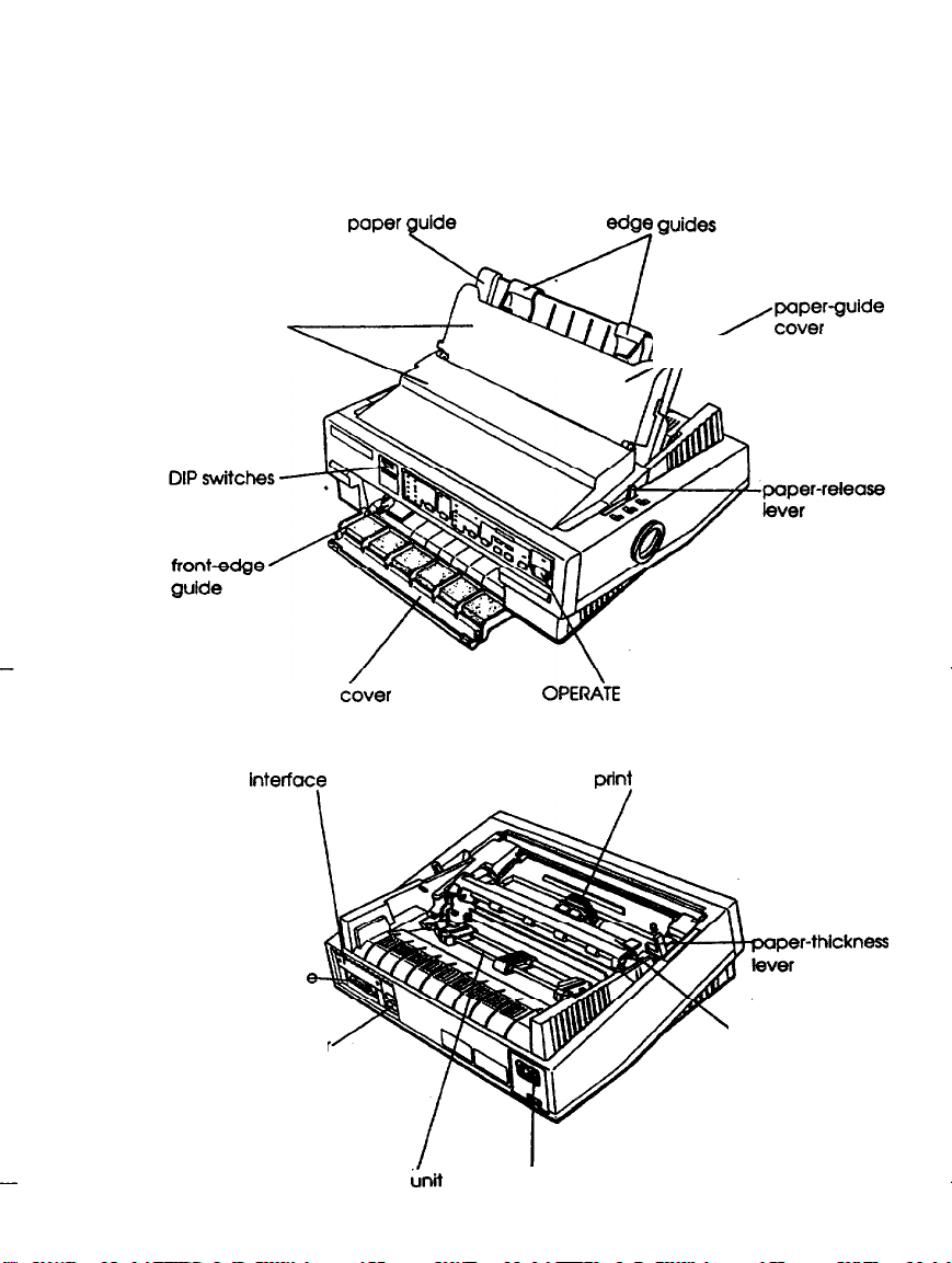
Printer Parts
paper guide
\
printer cover
interfay
T/
front
&over
cover
Y
OPERATE switch
prtnf
guide;~Zguide
head
parallel lnterfac
ground connector
tractor
L-bit
paper-tension unit
AC inlet
Page 4
TIPS FOR PRINTING ON SINGLE SHEETS
There are a few things you should know about printing on
single sheets as opposed to continuous paper. When you print
on single sheets, you may notice that your printer prints the
first page of your file correctly but then prints too low on the
next page, or that it prints the last few lines
the next.
These differences in print position are easy to adjust; you can
simply change some of the settings in your software as
described below to get the right results.
1.
When you install software, it normally ask you what printer
you are using. Make sure you choose the correct printer.
See Chapter 1 for the right printer to choose.
2
Many programs include an option to set the maximum lines
per page. If your program has a lines-per-page setting and
you are using standard 8% x 11-inch paper, set the lines
per page to 61.
Note:
To find’Uut tight
II,createatestdaru~~gyour~Setyourtopand
boftommarginstoOandthenaerrfeafileofnumberedlinesFwn
I
to 66. when you
on the first
lines-F-pge &ting for paper
plirlt purjzle, notice
page. This
is your maximum lines-per-page
the
from one
page onto
that is not 8% x
last
number
setting.
pri?lted
3.
If your program doesn’t have a lines-per-page setting, try
decreasing the top margin or increasing thebottom
margin, or both, until you get the results you want.
4.
You can also try adjusting the form length setting. For a
standard 8% x 11-inch page, try setting the form length at
10 inches
5.
Some programs also let you indicate whether you are using
single sheets or continuous paper. Make sure you choose
single sheets.
iii
Page 5

Where to Get Help for
United States Users
Epson America provides customer support and service
through a nationwide network of authorized Epson dealers
and Service Centers.
Epson also provides the following support services through
the Epson Consumer Resource Center at (800) 922-8911:
Assistance in locating your nearest Authorized Epson
0
Reseller or Service Center
0
Technical assistance with the installation, configuration,
and operation of Epson products
Information on software drivers
cl
Cl
Sales of the Epson ESC/P® Reference
contains comprehensive information on ESC/P 2™
Epson technical information library fax service
cl
Product literature with technical specifications on our
Cl
current and new products
0
Sales of ribbons, supplies, parts, documentation, and
accessories for your Epson product
Customer Relations
cl
0
Information about user groups
Manual, which
Page 6

For United Kingdom Users
Epson product guarantee
Under the law, goods sold must comply with their description
and must be of merchantable quality and fit for their purpose
or correspond with any sample.
This guarantee does not affect the seller's legal obligation or
the rights of the consumer in the “consumer transactions”
under any Statute, including Sections 12 to 15 of the Sales of
Goods Act, 1979.
All Epson Products, other than OEM products, are fully
guaranteed against faulty operation or performance for a
period of ONE YEAR from date of purchase by the w of the
product.
All claims under this guarantee MUST be supported by
evidence of purchase, normally the bill of sale invoice, and it is
the responsibility of the claimant to furnish such proof. Epson
(UK) Limited does not issue or operate any form of guarantee
registration card.
Claims are made by the user returning the product to the
supplier from whom it was purchased or, if this is impractical,
to any Epson supplier who also handles the same product. In
the event of any difficulty, users are requested to contact the
Service Co-ordinator Manager at Epson (UK) Limited.
Epson (UK) limited, or
their discretion repair or replace part or all of the product to
provide, in their judgement, a satisfactory performance of the
product consistent with its age and apparent usage.
This guarantee covers the cost of both the parts and labour
required to correct any malfuntion of the equipment, but
specifically excludes: wear and tear, consumables, physical
damage due to unauthorized and inexpert repair.
Epson Appointed Distributors, will at
Page 7

The guarantee is restricted to the performance of the product
alone; and Epson (UK) Limited does not accept responsibility
for any consequential loss or damage, nor claimed or implied
performance, when the product is used in any combination
with other equipment or program software.
Product guarantee may be invalidated as a result of excessive
or inappropriate use, use in adverse environment or in
conditions outside the specifcations or if the product has been
subjected to unapproved modifications.
The guarantee does not cover visits to the user’s premises or
the repair or commissioning of the product on site.
Use of options
Epson (UK) Limited shall not be liable against any damages or
problems arising from the use of any options or consumable
products other than those designated as Original Epson
Products or Epson Approved Products by Epson (UK) Limited.
Safety information
Warning: This appliance must be earthed. Refer to rating plate
for voltage and check that the appliance voltage corresponds to
the supply voltage.
Important: The wires in the mains lead fitted to this appliance
are coloured in accordance with the following code:
Green and yellow-Earth
Blue - Neutral
Brown - Live
As the colours of the wires in the mains lead of this appliance
may not correspond with the coloured markings identifying
the terminals in your plug, proceed as follows:
vi
Page 8

The green and yellow wire must be connected to the terminal
in the plug which is marked with the letter B or with the earth
symbol (+I or coloured green or green and yellow.
The blue wire must be connected to the terminal in the plug
marked with the letter N or coloured black.
The brown wire must be connected to the terminal in the plug
marked with the letter L or coloured red.
If damage occurs
qualified electrician.
Replace fuses only with a fuse of the correct size and rating.
to the plug, replace the cord set or consult a
vii
Page 9

IMPORTANT SAFETY INSTRUCTIONS
Read all of these instructions and save them for later
1.
reference.
Follow all warnings and instructions marked on the product.
2
Unplug this product from the wall outlet before cleaning. Do
3.
not use liquid cleaners or aerosol cleaners. Use a damp
cloth for cleaning.
4.
Do not use this product near water.
Do not place this product on an unstable cart, stand, or table.
5.
The product may fall, causing serious damage to the
product.
Slots and openings in the cabinet and the back or bottom are
6.
provided for ventilation to ensure
product and to protect it from overheating, these openings
must not be blocked or covered. The openings should
never be blocked by placing the product on a bed, sofa,
rug, or other similar surface. This product should never be
placed near or over a radiator or heat register. This product
should not be placed in a built-in installation unless proper
ventilation is provided.
reliable operation of the
viii
7.
This product should be operated from the type of power
source indicated on the marking label. If you are not sure
of the type of power available, consult your dealer or local
power company.
This product is equipped with a 3-wire grounding-type plus,
8.
a plug having a third (grounding) pin. This plug will only
fit into a grounding-type power outlet. This is a safety
feature. If you are unable to insert the plug into the outlet,
contact your electrician to replace your obsolete outlet. Do
not defeat the purpose of the grounding-type plug.
Page 10

9.
Do not locate this product where the cord will be walked on.
10. If an extension cord is used with this product, make sure
that the total of the ampere ratings on the products
plugged into the extension cord does not exceed the
extension cord ampere rating. Also, make sure that the
total of all products plugged into the wall outlet does not
exceed 15 amperes.
11. Never push objects of any kind into this product through
cabinet slots as they may touch dangerous voltage points
or short out parts that could result in a risk of fire or
electric shock. Never spill liquid of any kind on the
product.
12. Except as specifically explained in the User’s Manual, do not
attempt to service this product yourself. Opening or
removing those covers that are marked “Do Not Remove”
may expose you to dangerous voltage points or other risks.
Refer all servicing in those compartments to service
personnel.
13. Unplug this product from the wall outlet and refer servicing
to qualified service
personnel under the following
conditions:
A.
When the power cord or plug is damaged or frayed
B.
If liquid has been spilled into the product
C. If the product has been exposed to rain or water
D.
If the product does not operate normally when the
operating instructions am followed. Adjust only those
controls that are covered by the operating instructions
since improper adjustment of other controls may result
in damage and willoften require extensive work by a
qualified
technician
to restore the product to normal
operation.
Page 11

E.
If the product has been dropped or the cabinet has been
damaged.
F.
If the product exhibits a distinct change in performance,
indicating a need for service.
Page 12

Contents
lntroduction
Features..
More about ESC/P2
Options
Finding Your Way Around
Warnings, Cautions, and Notes
Chapter 1
Unpacking the Printer
checking the parts
Choosing a Place for the Printer
Assembling the Printer
Removing the protective materials
Installing the ribbon cartridge
Attaching the paper guide
Testing the Printer
Plugging in the printer
Running the self test
Connecting the Printer to Your Computer
Configuring Your Software for the Printer
Choosing from a menu
...........................
.....................
.............................
............... ..
.............
Setting Up the Printer
........................
.......................
..................
.......................
.............
................
..................
...........
..............
....................
......................
............
...........
....................
.
1
2
2
4
4
1-2
1-2
1-3
l-4
1-4
1-4
l-8
l-9
l-9
1-9
1-12
1-14
1-14
Chapter 2 Paper Handling
Selecting a Paper Feeding Method
.................
Setting the paper-release lever
Using Single Sheets
.........................
Loading single sheets from the top
Loading single sheets from the front
................
.............
............
2-2
2-2
2-3
2-3
2-5
xi
Page 13

Using Continuous Paper
......................
Tractor position and available paper paths
Changing
tractor positions
.................
........
2-7
2-7
2-8
Installing in the push-tractor position-Installing
in the pull-tractor position
Loading continuous paper with the push tractor
Removing continuous paper from the push tractor.
Loading continuous paper with the pull tractor
Removing continuous paper from the pull tractor
Switching Between Continuous Paper and Single Sheets
Switching to single sheets
Switching to continuous paper
Printing on Special Paper
......................
Paper-thickness lever
Multi-part forms
........................
..................
...............
.....................
..... 2-10
...
2-13
.....
2-14
.... 2-18
...
2-18
2-18
2-20
2-20
2-21
2-22
Labels. .. .. .. ... .. .. ... ... ... ... ... ... ... ... ... ... .. . . .. .. . ... .... 2-22
Envelopes.
...........................
2-24
Chapter 3
Using the Printer
Control Panel. . . . . . . . . . . . . . . . . . . . . . . . . . . . . 3-2
Lights.............................................................................3-2
Buttons . . . . . . . . . . . . . . . . . . . . . . . . . . . . . 3-3
Other control-panel features . . . . . . . . . . . . . . . . . 3-5
DIP Switches . . . . . . . . . . . . . . . . . . . . . . . . . . . . . 3-6
Changing a DIP-switch setting . . . . . . . . . . . . . . . 3-6
DIP-switch tables . . . . . . . . . . . . . . . . . . . . . . . 3-7
DIP-switch functions . . . . . . ._ . . . . . . . . . . . . . . 3-9
International character
sets-Character tablesPrint direction-Printer mode-Input buffer
capacity-Skip-over-perforation-Continuous-paper page length-Tear off-Auto
line feed
Micro Feed . . . . . . . . . . . . . . . . . . . . . . . . . . . . . . 3-13
Using micro feed . . . . . . . . . . . . . . . . . . . . . . . 3-13
Adjusting the loading position . . . . . . . . . . . . . . . .3-14
xii
Page 14

Tear Off
................................
Tear-off mode
.........................
Using the TEAR OFF button.
Adjusting the tear-off position
Typestyles.
Character fonts.
Character spacing
Condensed printing
Data Dump Mode..
..............................
........................
.......................
......................
........................
.................
................
3-16
3-16
3-17
3-18
3-19
3-19
3-24
3-25
3-25
Chapter 4
Using Printer Options
Cut-Sheet Feeders . . . . . . . . . . . . . . . . . . . . . . . . . .
Installing a cut-sheet feeder . . . . . . . . . . . . . . . . .
Loading paper with the single-bin cut-sheet feeder. . . .
Loading paper or envelopes with the high-capacity
cut-sheet feeder . . . . . . . . . . . . . . . . . . . . . . .
Assembling the double-bin cut-sheet feeder . . . . . . . .
Switching between continuous paper and the cut-sheet
feeder . . . . . . . . . . . . . . . . . . . . . . . . . . . . .
Switching to continuous paper-Switching to the
cut-sheet feeder
Pull Tractor ..................................................................
Loading paper with the push tractor and the optional
pull tractor . . . . . . . . . . . . . . . . . . . . . . . . . .
Interfacecards............................
Installing an interface card . . . . . . . . . . . . . . . . . .
The C823051/C823061 serial interface card . . . . . . . .
Selecting a baud rate-Handshake timing-Error
handling
Chapter 5
Maintenance and Transportation
4-2
4-2
4-3
4-6
4-8
4-11
4-12
4-12
4-14
4-14
4-16
Cleaning the Printer
Replacing the Ribbon
..........................
........................
Transporting the Printer
......................
5-2
5-3
5-3
xiii
Page 15

Chapter 6 Troubleshooting
Power Supply
............................
6-2
Printing.............................................................................. 6-2
Paper Handling
Chapter 7 Technical Specitications
Printer Specifications
Printing
Paper
Mechanical
Eletrical
Environmental
Interface Specifications
Specifications and pin assignments
Interface timing
Option Specifications
Cut-sheet feeders
Initialization
Default settings
Chapter 8 Command Summary
...........................
........................
............................. 7-2
.............................
........................... 7-7
............................. 7-7
.........................
.......................
............. 7-9
........................
........................
....................... 7-12
.............................
........................ 7-14
6-7
7-2
7-4
7-8
7-9
7-12
7-12
7-14
Using the Command
Commands Arranged by Topic
General operation
Paper feeding
Page format
Print position motion
Font selection
Summay .................................................................... 8-2
..................
.......................
8-2
8-2
......................... 8-3
.......................... 8-3
...................... 8-4
............................................................. 8-6
Font enhancement................................................................................ 8-7
Character handling ....
Spacing
Graphics
Bit image
xiv
............................. 8-11
...........................
............................
..........................
8-8
8-11
8-12
Page 16

Appendix
Character Tables
Italic Character Table
...........................
.....................
Graphics Character Tables
International Character Sets
Glossary
Index
....................
..................
A-2
A-2
A-3
A-8
xv
Page 17

Introduction
These features make your Epson printer an outstanding value:
0
Quiet operation. This printer makes far less noise than
previous dot-matrix printers.
0
Fast printing speed. You can print up to 269 characters per
second in 12-cpi draft mode.
A wide choice of scalable fonts. Four scalable fonts are
c1
available: Epson Roman, Epson Roman T, Epson Sans Serif,
and Epson Sans Serif H.
0
Easy paper handling. The printer has four paper paths to
suit your printing needs: top, rear, bottom, and front.
‘0
Epson’s ESC/P 2™. This is the first dot-matrix printer
control language to offer scalable fonts and enhanced
graphics.
0
Compatibility. The printer supports the Epson ESC/P
commands widely used in application software.
®
0
Unique control-panel design. You can choose from nine
popular letterquality fonts and one draft font.
0
IBM® emulation mode (European version only). This mode
emulates IBM Proprinter X24E and XL24E.
The LQ-570+ and LQ-1070+ are basically the same printer
except for the width of their carriages. The LQ-570+
accommodates paper up to 254 mm (10 inches) wide. The
LQ-1070+ accommodates paper up to 355.6 mm (14 inches)
wide.
Page 18

More about ESC/P 2
Epson’s enhanced printer control language, ESC/P 2, offers
four scalable fonts in sizes from 8 to 32 points. You can use this
feature if your software supports scalable fonts. For DOS-based
word processing software, new ESC/P 2 drivers may be
available to enable your software to use your printer's scalable
fonts. Contact your software manufacturer or Epson to ask
about special ESC/P 2 drivers.
For graphics-based software, such as Microsoft’ Windows”,
ESC/P 2 works with your software to provide enhanced
graphics printing capability. In the Windows environment,
you’ll be able to print the Windows scalable fonts instead of
the Epson fonts.
If you’re an experienced printer user, you may also want to
order the
programming information. Contact your Epson dealer or see
Where to Get Help for United States Users in this manual for
further information.
Epson ESC/P Reference
Guide for complete
Options
For more information on these option, see Chapter 4.
0
Single-Bin Cut-Sheet Feeder
KM%37*
This economical cut-sheet feeder automatically feeds up to
50 sheets of paper into your printer without reloading. You
can load continuous paper and manually load single sheets
without removing the
P
High-Capacity Cut-Sheet Feeder
(C80638*
This cut-sheet feeder automatically feeds up to
of paper
You can create
this cut-sheet feeder to the single-bin model.
2 Introduction
for
4-570+,
for
4-570+, CBO640*
or 25 plain bond envelopes
C80639*
cut-sheet
a double&in cut-sheet feeder by connecting
for
LQ-1070+)
feeder.
for
LQ-1070+)
without reloading.
150 sheets
Page 19
Pull-Tractor Unit
0
030019*
for
LQ-570+, cBOO22*
for
LQ-1070+)
Using this option along with the standard tractor improves
printing accuracy, which is especially useful for printing
on multi-part forms.
Film Ribbon Cartridge
cl
(#7768 for
An optional
LQ-570+, #7770
film
ribbon cartridge provides even higher
for
LQ-1070+)
quality printing than the standard fabric ribbon.
Interface Cards
a
6
Optional interface cards are available to supplement the
printer’s built-in
para.Uel
interface. See Chapter 4 for more
information.
The last figure in option part numbers, represented by an
asterisk
(~1,
varies by country. Contact your local Epson dealer
for the part number in your country.
Page 20

Finding your Way Around
This manual provides fully illustrated, step-by-step
instructions for setting up and operating your printer.
0
Chapter 1 contains information on unpacking, setting up,
testing, and connecting the printer.
chapter
cl
Chapters 2 and 3 include important information on paper
handling and day-today operation of your printer.
a
Chapter 6 contains tmubleshooting information. If the
printer does not operate properly or the printed results are
not what you expect, see Chapter 6 for a list of
and solutions.
cl
Other chapters contain information on options, general
maintenance,
the end of this manual for a glossary of printer
an index.
Arst.
spedficatkm,
and printer comman
J3e
sure to read this
Warnings, Cautions, and Notes
pmblems
d&see
tems
and
Warnings must
P
Cautions must be obsenxd to avoid damage to your equipment.
&N
Notes contain
?fyour
4 Introduction
printer.
6efblhxd
import@ injbmation
to
a7d
bodily
and useful tips on the operation
injuy
Page 21

Chapter 1
Unpacking the Printer. . . . . . . . . . . . . . . . . . . . . . . . 1-2
Checking the parts . . . . . . . . . . . . . . . . . . . . . . . . 1-2
Choosing a Place for the Printer . . . . . . . . . . . . . . . . . . 1-3
Assembling the Printer
Removing the protective materials
Installing the ribbon cartridge
Attaching the paper guide
Testing the Printer
Plugging in the printer
Running the self test
Connecting the Printer to Your Computer . . . . . . . . . . . . 1-12
Configuring Your Software for the Printer
Choosing from a menu
.......................
...............
.................
.....................
..........................
......................
.......................
............
......................
1-4
1-4
1-4
1-8
1-9
1-9
l-9
1-14
l-14
Setting Up the Printer
1-1
Page 22
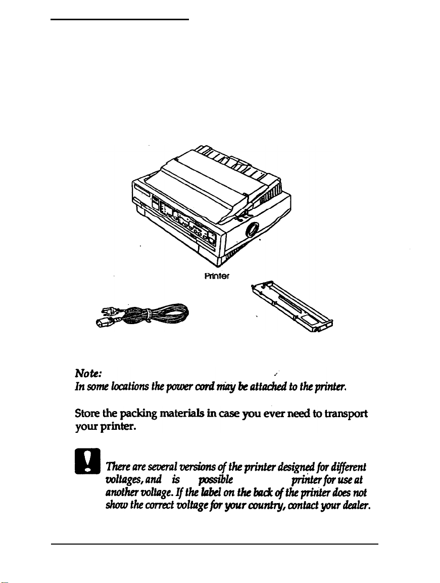
Unpacking the Printer
Checking the parts
When you unpack the printer, make sure you have all the parts
shown below and that none is damaged.
1-2
Power cord
Caution:
Q
‘Ihere~SeWalVe?ShS
uoltages,and
another~l~ge.Ifthelobclonfhckackqftheprinterdoesnot
shaothecorrectwl~gefotyrnrr~ntry,aontactyourdealer
Setting Up the Printer
it is not
Rlbbon cartridge
oftheprinterdesignedford~~
pssible
to adjust the
piiterfi3r
useat
Page 23
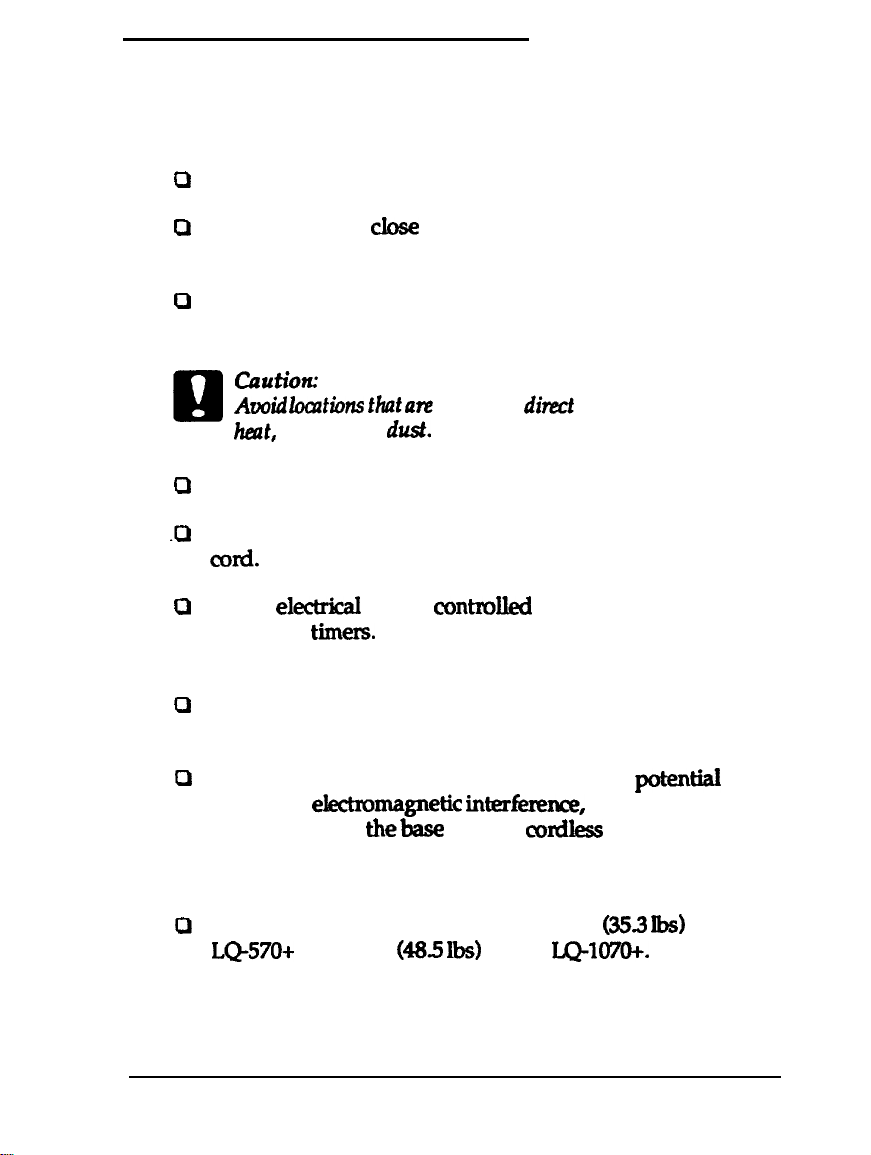
Choosing a Place for the Printer
When selecting a place to set up your printer, be sure to follow
the guidelines below.
0
Place the printer on a flat, stable surface.
0
Place the printer
printer’s interface cable to reach it.
0
Leave adequate room around the printer to allow for easy
operation and maintenance.
cautio?c
Awid
Q
Use a grounded outlet do not use an adapter plug.
Q
Place the printer where you can easily unplug the power
.a
loadions
heat,
moisture, or
cord.
0
Avoid
elect&al
automatic
out information in the memory of your printer or computer.
outlets
timers.
&se
enough to the computer for the
that
ate
subject to
dust.
contx&d
direct
sunlight, excessive
by wall switches or
Accidental disruption of power can wipe
cl
Avoid outlets on the same circuit as large motors or other
appliances that can cause fluctuations in line voltage.
0
Keep the entire computer system away from potential
sources of ekxtnxnagnetic interference such as
loudspeakers or
thebase
units of con3ess telephones.
If you plan to use a printer stand, follow these guidelines:
0
Use a stand that supports at least 16.0 kg
L&)-570+
or 22.0 kg
(48.5 lbs)
for the
Setting Up the Printer
(3!53 lbs)
LQ-1070+.
for the
1-3
Page 24
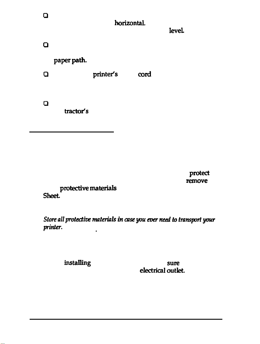
Never use a stand that tilts the printer at an angle of more
0
than 15 degrees from
horizontaL
If you install a cut-sheet
feeder, the stand must keep your printer
If you plan to load continuous paper through the bottom of
0
the printer, choose a stand that provides an unobstructed
paper
pa**
0
Position your
printeis
power cord and interface cable so
they do not interfere with paper feeding. If possible, secure
the cables to a leg of the printer stand.
a
Align the paper stack so that the paper feeds straight into
the
tract&s
sprocket units.
Assembling the Printer
Removing the protective materials
1eveL
During shipping, several pieces of packing material
printer. Before you assemble the printer, you must remove
these protective materials as shown in the attached Notice
Sheet.
Note:
Installing the ribbon cartridge
Before instaIling the ribbon cartridge, make sufe that the
power cord is
1-4
Setting Up the Printer
not
plugged into an
eIect&al outlet.
pro&t
the
Page 25
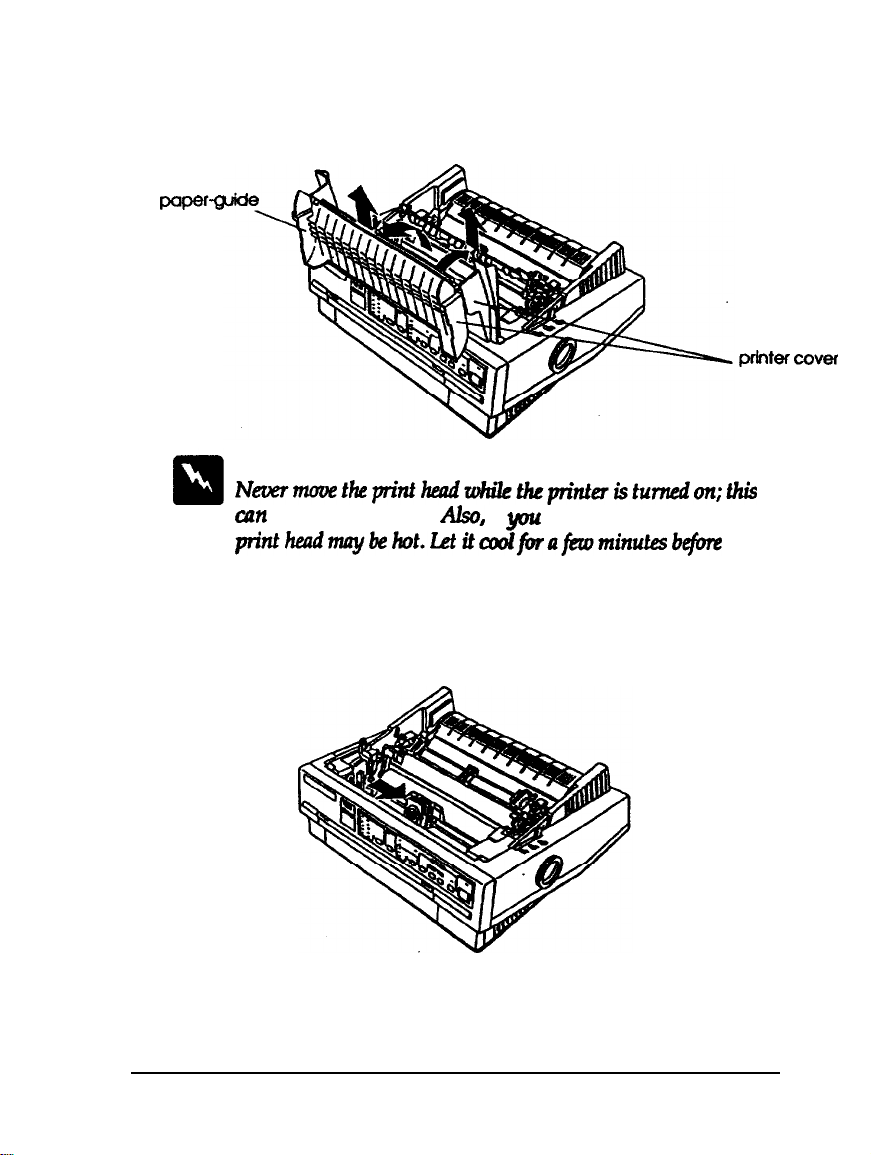
1.
Raise the paper-guide cover and rest it on the printer cover.
Lift the paper guide up and off. Lift the printer cover up
and off. Grasp both ends of the clear plastic paper-tension
unit; lift up the front of the unit and then lift it off.
WWQ
cover
Warning:
Ntsermovetkprinthtndwhilctheprinteristurnedon;this
cun damage the printer. Also, if
pn’ntheadmaybehot.~itoodforaferominu~be3fore
touching it.
2
Slide the print head to the middle of the printer.
you
just used the printer, the
prbltercover
Setting Up the Printer
1-5
Page 26
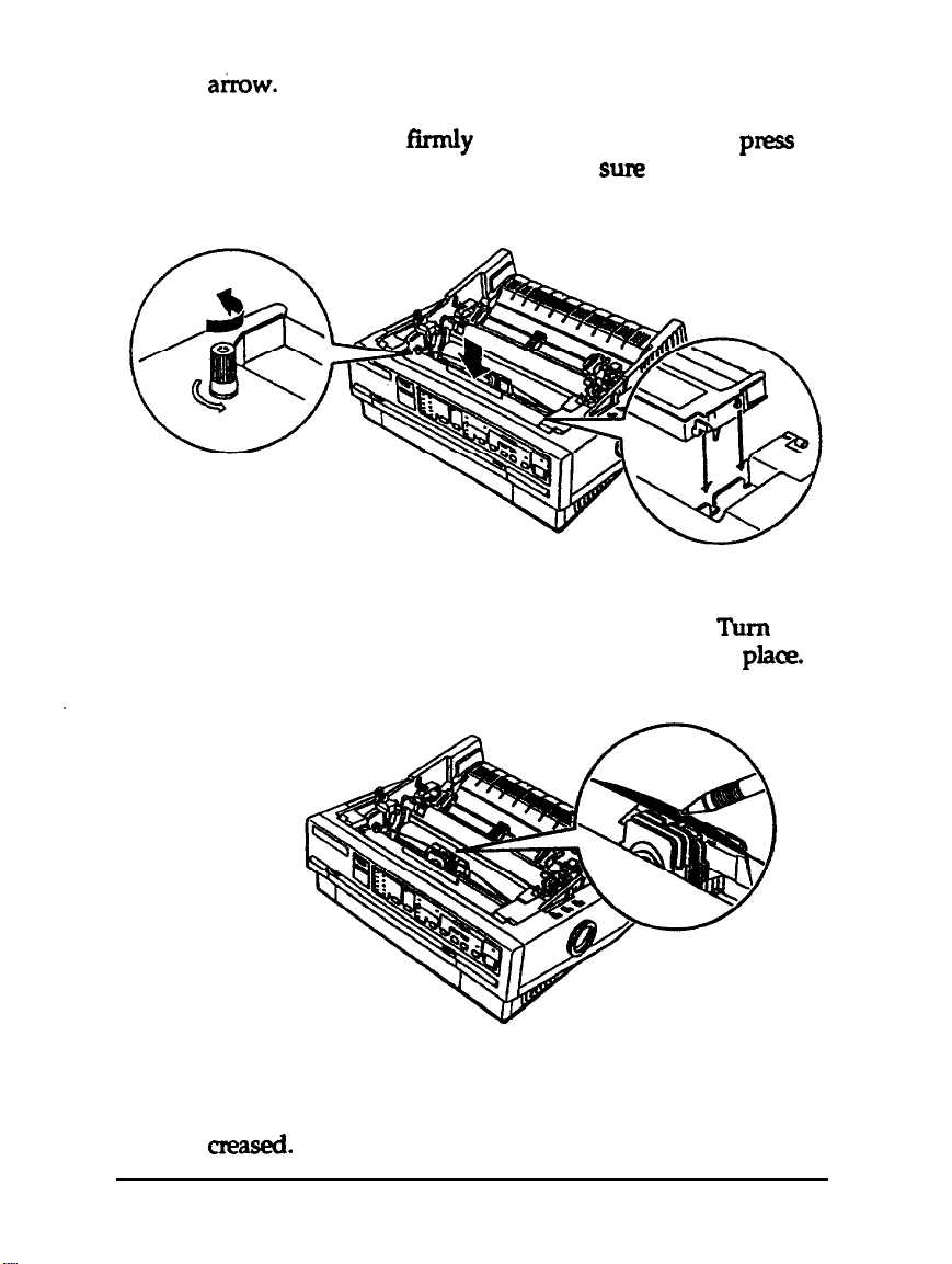
3.
Turn the ribbon-tightening knob in the direction of the
a&w.
This removes any slack in the ribbon and makes it
easier to install. Next, hold the ribbon cartridge by its
handle and push it
fixmly
down into position; then
pnzss
on both ends of the cartridge to make sum the plastic
hooks fit into the slots.
4.
Use a pointed object, such as a ball point pen, to guide the
ribbon between the print head and ribbon guide. Turn the
ribbon-tightening knob to help feed the ribbon into
pla<~.
1-6
5.
Slide the print head from side to side to make sure it moves
smoothly. Also check that the ribbon is not twisted or
cre&.
Setting Up the Printer
Page 27
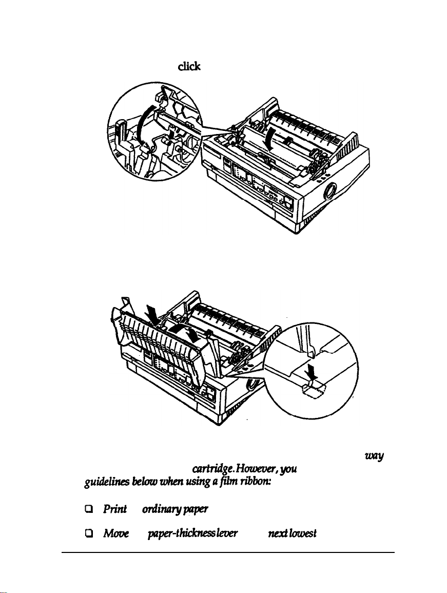
6.
Replace the paper-tension unit by placing it on the printer’s
mounting pegs; then lower the front of the unit into place.
Press on the front of both sides of the paper-tension unit
until you feel it
7.
Replace the printer cover by first inserting the front tabs into
ckk
into place.
the slots on the printer, then lower it into place.
Note:
You install the optional #7768 or #7770 film ribbons in the same
pu
as you install the ribbon
guWinest&wwhenusingaj?lmribbox
P
Print
on
oniinanj paper
P
Mum
the
pper-t~
cxrtridge.
only.
leuer
Huwever,
to the
should follow the
nexI lavest
Setting Up the Printer
position.
unzy
1-7
Page 28
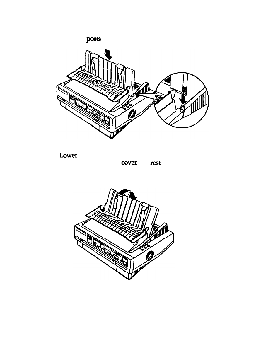
Attaching the paper guide
Place the notches on the paper guide straight down over the
1.
mounting
Lower
2.
.
Raise the paper guide cover and
guide.
p&s
on the printer.
the paper guide until it stops in the upright position.
nest
it against the paper
1-8
Setting
Up
the Printer
Page 29
Testing the Printer
Before connecting your printer to a computer, use the built-in
self-test function to see that the printer is working properly.
Before running the self test, you need to plug your printer's
power cord into an electrical outlet.
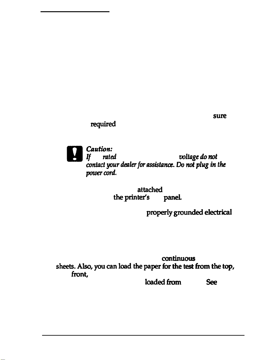
Plugging in the printer
1.
Make sure the printer is turned off.
2
Check the label on the back of the printer to make
voltage
nquired
by the printer matches that of your
electrical outlet.
ciaution:
If
m
3.
If the power cord is not attached to the printer, connect it to
the AC inlet on
the rated voltage and your outlet voltage do not match,
lTontadyourdtnlerfor&tarKx.Do~pluginthe
pouner~.
theprinteis
rear
par&
sun2
the
4.
Plug the power cord into a properly
gxxmded electrical
outlet.
Running the self test
You can run the self test with either
sheek.Also,youcanloadthepaperborthetestfromthetap,
mar, front, or bottom. The following steps describe how to run
the test on single-sheet paper,
2
for full details on paper handling.
loadd
ctM.nuous
fmm the top.
Setting Up the Printer
paper or single
See
Chapter
1-9
Page 30
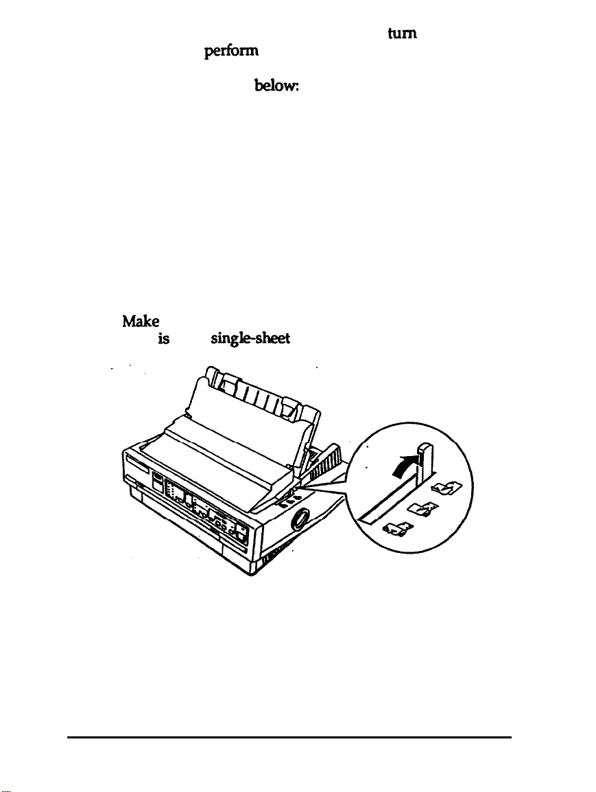
By holding down a certain button while you
printer, you can
perfom
the self test in draft or LQ mode, or
turn
on the
you can print out a list of the current DIP-switch settings.
These buttons are listed
below
LOAD/EJECT
LF/FF
ALT
Draft mode self test
LQ mode self test
DIP-switch setting list
The self test begins by printing on the first and last lines of
page 1. The printer then print the character samples on page 2
If you select LQ mode, the printer print the self test in every
font, in turn.
1.
h4ake
sure the printer is turned off and that the paper-release
lever is in the
sin&sheet
position.
1-10
2.
While holding down the appropriate button, turn on the
printer. The printer beeps and the platen turns for a few
seconds, signaling that the printer is in self-test mode.
Setting Up the Printer
Page 31

3.
Move the left edge guide until it locks in place next to the
guide mark. Then adjust the right edge guide to match the
width of your paper.
Caution:
Fun
the self test using paper at least
fortheLQ-57O+or36Omm(Z4iruhs)rctide~
LQ-2070+; otkrwGe, tk
plilten.
print
220
mm (8.2
kud
prints directly on
inches)
tk
wide
tk
4.
Insert a sheet of paper between the edge guides until it meek
resistance. After a few seconds, the printer loads the paper
to the loading position andbegins printing the self test.
Setting
Up the
Printer
1-11
Page 32

5.
To stop the self test, press the PAUSE button (you can resume
the self test by pressing the PAUSE button again).
6.
Press the LOAD/EJECT button to eject the paper from the
printer and then turn the printer off.
If test results are not
satisfadtxy,
see Chapter 6.
Roman
“‘#$%&‘()*i.-./01234567!39:;<=>?@ABCDEFGHIJKl
‘“#$%&‘o*+
;‘t$%&‘( I*+,
,-./0123456789:
-./0123456789::
;<=>?@ABCDEFGHIJKLb
<=>?OABCDEFGHIJKLMl
#$%&‘()*+,-./0123456789:;<=>?BABCDEFGHIJKLMN(
$%&‘(I*+,-.
/0123456789:
;<=>?BABCDEFGHIJKLMNOl
Connecting the Printer to Your Computer
If the self test prints
printer to the computer. Use a shielded twisted-pair
cable to
connect
interface.
Connect the parallel interface cable as
your
co&y,
amputer
you are ready to
conned
parakl
to the print&s built-in
dexribed belowz
your
parakl
1-12
Setting Up the Printer
Page 33

1.
Make sure both the printer and computer are turned off; then
plug the cable connector securely into the
printeis
parallel
interface connector. Squeeze the wire clips together until
they lock in place on either side of the connector.
Note:
If your
cable
has a
ground toire, connect
it to the
gmnd con-
besidetheinttrfceaonnadar.
2.
Plug the other end of the cable into the computer.
(if
there is
a ground wire at the computer end of the cable, attach it to
the
gxwnd
connector at the back of the computer.)
Setting Up the Printer
1-13
Page 34

Configuring Your Software for the Printer
Most software lets you specify the type of printer you use so
that you can take full advantage of the print&s features. Your
software probably provides an installation or setup section that
presents a list of printers.
Choosing from a menu
To take full advantage of your printer’s features, including
ESC/P
the menu. If these printers are not listed, contact the software
manufacturer or see “Where to Get Help for United States
Users” at the beginning of this manual to see
the software is available. Until you receive an update, choose
from the following
ActionPrinter 5000+
ActionPrinter 5000
LQ-570/1070
LQ-870/1170
LQ-100
SQ-870/1170
LQ-510/550
LQ-500
LQ-860 / LQ-1060
LQ-850 /LQ-1050
LQ-2550
2,
choose the
LQ-570+/1070+
listz
or Stylus 800/1000 from
ifan
update to
If none of these printers is listed, select the first one available
from the following
listz
LQ, FX, LX, RX, MX, Epson printer,
Standard printer,Draft printer. Because some of the printers in
this list are 9-pin printers, your graphics printing may not be
correct.
1-14
Setting Up the Printer
Page 35

Chapter
2
Paper Handling
Selecting a Paper Feeding Method
Setting the paper-release lever
Using Single sheets . . . . . . . .
Loading single sheets from the top
Loading single sheets from the front
Using Continuous Paper
Tractor position and available paper paths
Changing tractor positions
Loading continuous paper with the push tractor.
Removing continuous paper from the push tractor
Loading continuous paper with the pull tractor
Removing continuous paper from the pull tractor
Switching Between Continuous Paper and Single Sheets
Switching to single sheets
Switching to continuous paper
Printing on Special Paper
Paper-thickness lever.
Multi-part forms
Labels
Envelones
................................
.............................
......................
......................
......................
.........................
.................
.................
. . . . . . . . . . . . . . . . .
...............
..............
..........
...................
......
.....
.......
......
...
....................
.................
2-2
2-2
2-3
2-3
2-5
2-7
2-7
2-8
2-10
2-13
2-14
2-18
2-18
2-18
2-20
2-20
2-21
2-22
2-22
2-24
Paper Handling 2-1
Page 36

Selecting a Paper Feeding Method
Your printer can feed single sheets from the top and front and
continuous paper from the rear, front, and bottom. Also, you
can use the tractor unit for continuous paper as either a push
or pull tractor.
You will probably use only one or two of these methods on a
regularbasis.
This chapter explains the various methods of paper handling
and includes
suited to your specific needs.
nxwnmendations
on the feeding methods best
Setting the paper-release lever
The paper-release lever has three positions, with icons
indicating the type of paper and paper path for each position.
Single sheet This position is for loading single sheets.
2-2 Paper Handling
Page 37

Push tractor This position is for loading continuous paper from
the rear, with the tractor in the push-tractor
position.
Pull tractor
This position is for loading continuous paper
the mar,
pull-tractor position. Use this position when
you have installed both the push tractor and
the optional pull tractor.
front
or bottom, with the tractor in the
Using Single Sheets
Your printer can print on single
(5.8 inches) to 257 mm (10.1 inches) wide on the
from148mm(5JBinches)toau)mm(165~)wideonthe
LQ1070+.
You can load single sheets
printer.
sheets
of paper from 148 mm
tirn
either the top or front of the
Loading single sheets from the top
1.
Move
Make sure the paper guide is in the upright position
the paper-release lever to the
single&M
LQ570+
position.
from
and
Paper Handling 2-3
Page 38

2.
Turn on the printer. The OPERATE light on the control panel
comes on.
3.
Slowly slide the left edge guide until it stops next to the
arrow on the paper guide. Then adjust the right edge guide
to match the width of your paper.
4. Insert the paper fimly between the edge guides until it meets
xesistanoe;
paper to the loading
after a few seconds, the printer advances the
positkm
2-4 Paper Handling
Page 39

Caution:
LIsetheknobonthert’gtrtside4theprinteronly~oclaarpaper
jams
&en
printer or
tk printer is
cnuse
it to he tk
of. Othemise,
top+inm
you may
pith
damage
If the platen tums but the printer doesn’t load the paper,
completely remove the paper and x-e-insert it more firmly.
To eject the paper, press the LOAD/EJECT button.
Loading single sheets from the front
1.
Move the papernzlease lever to the
open the front cover.
singlesheet
position and
the
2
Turn on the printer. The OPERATE light on the control panel
comes on.
Paper Handling 2-5
Page 40

3.
Slide the edge guide until you feel it click into place at the
guide mark. You can slide the edge guide to the left in
1 /IO-inch
increments
to
inaease
the size of the left margin
on your paper.
4.
While aliening the
.
insert the paper
seconds, the printer loads the paper to the
papeis
fmnly
left edge with the edge guide,
until it meets resistance; after a few
kmding
position.
2-6 Paper Handling
Page 41

Use the
jmnszahenthepn’ntaisoff.Othenctise,yyoumaydmnagethe
printer ur
knob
awe
on the
it to
luse
right
the
side of
top-oj$nm
the printer only to
position.
clear
paper
If the platen turns but the printer doesn’t load the paper,
completely remove the paper and re-insert it more firmly.
To eject the paper, press the LOAD/EJECT button.
Note
7’he
printer’s built-in
!SOsheetsofejectedpaper.
stack
in front of the
paper gui& am
hold up to
Using Continuous Paper
You can print on continuous paper from 101 mm (4 inches) to
254 mm (10 inches) wide on the
‘inches) to 406 mm (16 inches) wide on the
LQ-570+
and from 101 mm (4
LQ-1070+.
Tractor position and
avai/abie
paper paths
You can feed continuous paper from the rear, front, or bottom.
Your printer comes with the tractor installed in the
push-tractor position, for feeding paper from the rear. To feed
paper from the front
pull-tractor position. You can also install an optional
0rWto~installthetractorinthe
pull
tradoranduseboththepushandpull~~~together.
Always move the paper-release lever to the position indicated
for the paper-feeding method you are using, as shown in the
table on page 2-8.
Make sure you align your paper supply with the paper loaded
in the tractor so the paper feeds smoothly into the printer.
Paper Handling 2-7
Page 42

If you
stand that has a large enough opening lor paper to feed from
thebottom without
feed
paper through the bottom paper slot, use a printer
obstructkm.
Puh-tractor
d
ful-tractaf
position
.
.
.
.
.
.
.
.
d
I
Changing tractor positions
Youonusethe~~runitasei~apushtractororapull
tractor.Youcanchangethelxxtorp&tkma~toyour
paperkedingmethod.TheprWerccm3eswiththetmctor
instakiintkpush-trackxposition.
1. Make sure the printer is turned off. Lift the printer cover and
the paper guide up and off the printer.
2.
If necessary, remove the tractor from the pull-tractor position
by pressing the tabs open while lifting the tractor up
and out of the mounting slots.
2-8 Paper Handing
Page 43

Press
3.
open the
horizontally above the printer and
intotheprinteA3bmkmountingslda
tract&s
.
lock
4.
5.
tabs.
Hold the
kwer
it
tmtar
sttalght
down
6.
7.
Page 44

3.
If necessary, remove the tractor
from
the
push-tractur
positionbypressingthehcktabsopenwhflellwngthe
tractorupandoutofthemountingshoQ
4.
Pushthetr~slocktabsintotheope!n~Tiltthe
tractorhwadand~itintotkpdnWsftont
moundngslotaAnatMwoneachsid@ddre-w
dotsshowsyouwhen?toalignthe~.
5.
Whenthettactorispo6itlonedinthem0un~s~~
thelocklalxL
2-10 Paper Handling
Page 45

Make
2.
paper-dease
sure the
tra&x
is in the push-tractor
position
lever is in the push-tractor position
and the
-
-
Page 46

4.
Slide the left sprocket unit using the scale on the printer as a
guide. The printer prints to the right of the position
markedO.Pushthespm&etbckkerbacktokxkitin
place.
of your paper, but do
‘Then
slide the r@ht sprocket unit to match the width
not lo&
it. Move the paper support
soitismidwaybetweenthespmcketti&
5.
Makesureyour&erhasadean,ibtmlgMleadingedge.
lknopenthespro&tcoversand&MeGiscthreeh&
ofthepaperoverthe~pinn
7.
Slidetherightsprocktunitto
lU?IMW~~sIadrhthepaper.
Thenlo&itinphxx!bypushingthesprodcetlodr~r
back
Page 47

8.
Place the notches on the paper guide
mounting
9.
Slightly lift the paper guide and then
posts on the printer.
straight
bwer %
theprMer.Rdsethepaperguklemverandrestitonthe
papergubdt.
10.
Slidebothedgegukksbthe~dtkppguMe.
ll.~ontheprin~.Theprinterad~thf?paperto~
loading
position
when it
nxeives
data
down over the
until it
resk
on
-
Page 48

Loading continuous paper with the pull tractor
By pIacing the tractor ii\ the pull-tractor position, you can load
paper from the rear,
for all paper paths.
Note:
Whmtktmctorf6intkpuaJraclor
EAR-oFFhttonw*LoAD/E
tO#UStllndby~
1.
Makesuretheprinterishuwdoffandthepapergukieand
theprintercoverare~ved.
fron~orbottom.Thestqs axe
donotwetk
R
buttontofczdtkpyIpokck
the same
2.
Makesurethetracbrisinthepulkacbr
paperhleverlsinthe~poeitbar
positionandthe
*
2-14
Paper Handling
Page 49

4.
Slide the left sprocket unit using the scale on the printer as a
guide. The
marked 0.
sprocket unit in
match the width of your paper, but do not lock it in
Move the paper
spxxxket unit&
5.
if you are
front
cover and slide the edge guide
printer prints
to the right of the position
Push the sprocket lock lever back to lock the
place.
Then slide the right sprocket unit to
place.
support
insert@
so it is midway between the
paper in thy front paper
completely to the left.
slot,
remove the
6. h4akesureyourpaperhasaclean,straightedge.hsertthe
paperintothedesiredpapersld(rpar,frontor~)
untilitemergesbetweentheplatenindprinthead.
Page 50

7.
Pullthepaperupuntiltheperfkatbnbetweenthefirstand
sand
pages is even with the top of
the prlnWs r&bun.
Page 51

10. Close the
sprucket
covers.
11. Slide the right sprocket unit to remove any slack in the
~w~-.‘l’&m lock it in place by pushing the spmcket lock
12.
Pkethel-lotdmonthepaperguidestrsightdowno~the
mounting posts on the printer.
13.
Sl&htlyliftthepePerguideandthenbwerituntiItlests
on the printer.
14. Slkiebothecigeguidestothemickile,ofthepap@rgufde.
15.
Tumontheprinter.
16.
ifnewsaxy,adjustthepaperpositionusingthemko-feed
katuredescribedfnchapkr3.
-
Page 52

Removing continuous paper from the pull tractor
1.
To Rmove continuous paper when using the
offthepaperata~~itentersthepapgs~.
puSI
tractor, tear
2
msaheWFFbuttdohedtheIlemalning’paper~
outoftheprhter.
.
I
Page 53

1.
If any rinted
EAR&F
button to
pobsition.
2
Tear off the printed
sheets remain in the printer,
advanm
the paper to the
pages.
pwss
tea&f
the
4.
Adjusttheedgeguidestomat&tbewidthdpurp&=
Ycnlcannowloads;ingleshtletsas
sheets”inthkchapter.
-
.
I
-in-JNsfngh
.:
Page 54

Switching to continuous paper
To switch from single sheets back b continuous paper in the
push tractor, follow the steps below
1.
Ifaslngle~tkinthepeperpath,p~theLOAD/EJECT
bUttOIHOC!jlXtt
3. SlidebothedgeguidestothemiddleofthepaperguLde.
4.
Move the
paper-
lever to the push-tractor p&ion.
2-20 Paper Handling
Page 55

Note:
Page 56

Yourprtntercanprintonbothsingle-sheetandconttnuous
mu&part brms.
You can load
singlesheet
multi-part
fixms
onlyinthefrontpaperslot.
YoucanusemultCpartfonnsofuptofourparts(includlngthe
original).Makesureyousetthepa~~kvertothe
properpositiox~ Use only carbonless multi-part
ti
Youloadmultl-partionnsthesamewayasywbaddngle
shixts
multi-part forms, it k
pull
or continuous paper.
installed in the
tractor.
For details, see
let3mmdedyaIusethe~
push-tractor
Wsing
Single
J?or
best results with
aMinuous
po&ion togethw with the optional
Sheets”
or
Toading
continuous
.
paperwiththepulltractor~earlierinthkchapter.Payspedal
attentiontosettingthek&ngpusitionasdesaIbedin”Using
micro-feed”inchapter3.
Whenprintinglabels,alwayschoosethetypemountedcma
continuousbackingsbtwithsprock&h&sforu8ewitha
tl?xtor.Donottrytoprintlabelsassinglesheetsbecaust?labels
onashinybackingsheetcioru3tf6edpqeriy.
Page 57

It is recommended you
paper slots with the tracks in the
load
labels
the
sane
thepullhxtor~,exceptyousetthepaperthkkneWkverb
po6itkm2
bad
labels from the
way that you
fiat
of bottom
puUractor po&ion.
load aMnuous
paper (with
ct
‘0
cl
You
I
Page 58

Page 59

Chapter 3
Using the Printer
Control Panel.............................................................................. 3-2
zght8.T
............................................................
3-2
Other control-panel features
DIP Switches
~;~Pb&setthg
DIP-&t&functb;r;::::.
Micro-Feed
Using micro-feed
Adjusting the loading position
TearOff
Tear-off mode
Using the TEAR OFF button
Adjusting the tear-off position
Typestyles
Character fonts
Character spacing
Condensed-
.............................
..............................
.........................
................................
...........................
..........................................................................
.........................
.........................
..................
......................................................
.................
................................................
3-5
3-6
3-6
3-9
3-13
3-13
3-14
3-16
3-16
3-17
3-18
3-19
3-19
3-24
3-25
Data Dump Mode
..............................
3-25
..
Using the Printer 3-1
I
Page 60

Control Panel
The indicator lights give you the current status of
The buttons let you control many printer
s&tin&L
OPERATE (green)
Onwhentfu?opecateswitchfsonandpowerksup~
the
printer.
-
I
I
Page 61

Using the Printer 3-3
.
I
Page 62

ALT
Use this button in combination with
the
following tmklx
otkbulton~ to perfhn
f3lJFFERCLEARPAUSQ
MICRO FEED
ttLOAD/=CTl
ClearstheprinMsbu&rand
inidalkestheprlntersettings.
Peedspaper6lmvaIdin
1/18@td tnaelmnb
Page 63

Note:
The typesty& samples on the panel are meant
printai lvsufts
may
d@.r
slightly.
11s gddes
Other control-panel features
Thecontmlpanelakogivesyouaccesstotwoothetspedal
flUKdtW.
only;
actual
selftest
Data dump:
Hold down the
LOAD/WECTbutton (lor draft
LF/FF
button (for LQ printing) or the
printing) while
tUmangOntheprlnber.Thl?selfteStletSp
~~yauP~~koperatfngPFoperfy.
HolddowntheALTbuttonwhiletumhgonthe
printertoPrintoutalktofthecumnt
DxP*witchse~
sehetheon~testingprinterinchapter
1
for more ilbkmnation.
HoIddowntheiF/FFandLOAD/~buttmi
Whik?~On~z;rintertOentepdata
dumpmochDatadumpmodealluws
advanoeduser3tofindthecauseof
ccImm&atiproblemsbetweentheprinter
andthemputer.
Thedatadum+odekmomhllyatplalnedat
theendoft.bk@ter.
I
Page 64

The tables below list the functions of the DIP switches. You can
see the current DIP-switch settings at any time by running the
self test as described in Chapter 1.
DIP switch 1
1-2
I
l-3
l-4
M
1-5
I
/l-7
1
l-8 / 1 -inch skip-over-perforation
** SW l-6 has no function on printers other than the European version.
I
sets/character tables
Print direction
/
Printer mode**
Input buffer
I
On
See the tables on the
page.
Unidirectional
Off
8 KB*
next
DIP switch 2
SW
2-l
Description
Page length (for continuous
On
See the Page length table
Off
paper)
2-2
2-3
2-4
*
The asterisks indicate the default or factory settings. The defaults for DIP
switches
Tear off
Auto line feed
l-l,
1-2, 1-3, 1-4, 2-1, and 2-2 vary according to the country.
On
On
Using the Printer 3-7
off*
off*
Page 65

on
14
otl
on
OI
af
011
an
on
on
Page 66

llhchmmm
at
Ott
11.7hchao96~
on on
ntlsst?ctimdesaibesthefun&msaftheDIpstitCheB.
Page 67

You
can select the character tables with DIP switches 1-1,1-2,
1-3,
and 1-4, according to
@Character
tables” on
page34
To select a graphics character table, you must first turn
switch 1-4 on.
Print direction
Printer mode
T&isfeatuxeisava&bIeodyontheEiuro~~ofthls
printer.
DIP
3-10 Using the Printer
Page 68

In IBM emulation mode, the functions of some DIP switches
differ from those listed on pages 3-7 to 3-9. These functions are
-Pm.@
48.
880
880
868
866
437Gled
858
862
l-l
on
,cm
on
on
oft
oft
‘otf
oft
Page 69

The printer stores data sent from your
buffer. Keep DIP switch 1-7 off to select an 8 KB
mmputer
in its input
bufkr.
WhenautolinekdisaaOXPswkh24orr),the~
aac0mpanieseach~retumcode(CR)~vedwltha
line-fi?edcade!m.
.
Page 70

If your printer is double spacing, turn DIP switch 2-4 off. If
each line overprints the next, turn DIP switch 2-4 on.
Micro Feed
The micro-feed feature allows you to move the paper forward
or
t&cward
feature to adjust the loading and
Before you adjust the loading position, it is set to the factory
setting (8.5
theloadingpositiontoas~~as5~mm~mthetopedgeof
the paper. You can then print more lines per page.
mn
you make adjustments to the loading or tear-off
posibIonswithoontinuous~~,theprinterremembersthe
new
position,
When you adjust the loading position of single-sheet paper, the
printer remembers the new position until you turn off the
power. The loading position returns to the factory setting
(85mm)whenthepoweristumedonagain.
in
l/180-inch inaements.
mm). By moving the paper backward, you can set
even if you turn off the printer.
You can use this
tear4
positions.
Tousethe~~feature,presstheALT~atthesame
time as you
indicated on the print&s control panel. To use the
feature,foBowthestepsbebw
1. Makesureprintinghasstopped.Ifnecessary,tifttheprinter
coverupsoyoucanseethepaperposition.
presq
the
LOAD/EJECT
or
LUFF
button, as
Using the Printer
mia&eed
3-13
Page 71

2.
While holding down the
buttontofeedthepaperfoxwardortheff~buttonto
feed the paper backward, as indicated by the arrows above
the buttons.
AL1
button, pmss the LOAD/EJECT
Page 72

3.
While holding down the
AL1
button, press the LOAD/EJECT
buttontoadjustthebadingp&iontoabwposltbnon
thepage;presstheLF/FFbuttontoadjustthebading
position to a higher position on
light keeps
i
fkhing
until the printer nxtzives data.
the
page.
The
MULTI-PART
Using the Printer 3-15
Page 73

Tear Off
AfkJWUhaVetihedprinting,yoUCanuSethe~ff
featureto8dvancxcontinu0uspapermtkpushtzMorto~
tearoffedgeofthepzinter.Youc8nthe!nessnytearoffprlnt0d
--yar
backlothebadfirgpositbh
Thisfeatult?leQyousavepaperthatwMlldnlmmanybelost
between documents.
Youcanusethe~ff~~inhvowayffbyhvningonDIP
switch2-3tosekctautmmtictearaffmode,orbypredngtk
TEAf?OfTbuttondnthemntdpanet
Ifthepe&uationbehveenpagesisnotaligmdwiththekaroff
edge,youcanadjusttheteamffpodt&nusingthe~~
fkatilre.
-P*ttng,*printer-paper
3-16 Using the Printer
Page 74

Enter tear-off
1.
h4akestmtheprhteristumaioff.
2
Turn DIP switch 2-3 an.
3.
~mtheprinterOh
mode
by
perfom
the
hollowing
steps:
WhenteaMfmodeisonandyoupxintoncontinuouspaper
onthepushtractor,t.heprinteradvantxsthe~prinkdpage
totheteaMff~ti~ThenyoucantearoffaIiprintedpages.
IftheperfoMonisnotalignedwiththe~edge,adjuat
thetearoffpositionasdescrkdinthesecHononadjustingthe
tear-offpositionhterinthkchapter.
~you
lesumeprtnting,theprinterfeedsthepaperbackto
thebadingpo6itbnandbegfns~dng.cyoucanalso
manuaIlykithepaperbacktotheloadingposit4onby
pressingthel.OAD/fiJECTorTEARoFFbutton3
Page 75

Adjusting the tear-off position
If the perforation is not aligned with the
the tear-off position by
h4akesumthepaperishtheteardpa6itianandthelEAR
1.
OFFlightison
2.
Tear off any printed pages
3.
4.
Mowhg the!
tear4
stepsbeknw
edge, adjust
3-18 Using the Printer
Page 76

Typestyles
You can produce a wide range of typestyles by combing
different
can select typestyles using the control panel
Your printer has I2 built-in
character fonts, widths, and other enhancements. You
cxyour
software.
The draft font uses
Thismakesitideal
Nme
Ietterquality
fonts produce
(LQ)
fon
fully-foxmed
doamen&
printefs controt
panel until
With Epson’s new’EiiC/P 2 p
alsokk!ctacataMebn~
fast printing.
work
alsoavaiIabIe.Letterquality
ctem
for
presntationquality
iightnexttoyourdesiredfont
cctntrd~youcan
l
”
andSansserifhws,s&tble
areavaihble;RoeMnTis
S&fHi@mihtO
Page 77

Roman
with.
boat
rishoo
with best wishes
with best wishes
with best wishes
with best wishes
with best wishes
with best wishes
RolXMIkT
rihbatufaba
with best
with best wishes
wishes
with best wishes
with best wishes
with best wishes
with best Wishes
3-20 Using the Printer
Page 78

Sons Serif
with
host wlshu
with best wishes
with best wishes
with best wishes
with best wishes
with best wishes
with best wishes
SansSedfH
wuhbe8twkh
wittlbestwishes
with best wishes
.
with best wishes
with best wishes
with best wishes
with best wishes.
Using the Printer 3-21
Page 79

The tOllowing shows sample characters for the draft
fonts
Epson Courier
and
LQ
I”#$%& ( )*+,-.
LHNOPQRSTW'WXYZ[\]-
mtyz{:)-Cuea~a6~~~~S~~~~~~u~Q~~~~f4R~~l6
GilRBPjr++io
l$sonRoman
/0123456789~;<=>?8CCDBFGHIJK
‘abcdefghijklamopqrstuv
Page 80

Epson Sans Serif Proportional
!‘?I$%&‘()*+,-./01234567S3:;<=>?OABCDEFGHIJK
LMNOPQRSTlJVWXYZ[U^,‘abcdefghijklmnopqrstuv
wxyz{:}“~OB~~~‘iTiAA~sR6tlbGQ~UO~fYPlfAf6
GfiRBQdnf*i~
Epson Prestige
Epson Orator
Epson Orator-S
-
-
Page 81

OCR-B
Character spacing
Characterspacings
pqmtional am
application
available for each font.
UseRomanTorSansSerifHfontonlyinpxqxxtionalmode
for best results.
The
printout below
prugraxn. !ke
This is
This is 12 cpi printing.
Thiiis pmportkmal printing.-
of10,12or15cpi(c~a~perinch)ani
available using
Chapter 7 for the chamckr spacings
amqwes
10Cypi
s&varecommands
the different tvpes
printing.
or your
ofsgwing:
3-24
Using the Printer
Page 82

Condensed printing
Condensed printing reduces the size of characters to
approximately 60 percent of their normal width, allowing
more characters to fit on a
and other applications where you need to print the maximum
amount of information on a page.
he.
This is
useful
for spreadsheets
You can condense 10 cpi, 12
using
s&warp
cannot condense
condensed 10 and
commands or your applkation program You
Scpi pxinting.
12cpi
Ibis is cordensed 10
This is
coadeased
cpi,
and proportional spacing
The printout below shows
printing.
cpi printing.
12
cpi
prirltinq.
Data Dump Mode
Datadumpmodeisaspecialf@aturethatallowsexperb&
usemtofindthecauseofcommunicationproblemsbetween
the printer and computer. In data dump mode, the printer
produces an exact
To use data dump mode, follow these
1.
Maketi~printerisoff.
2
Hold down both the
you turn on the printer.
printctut
of the codes it receive&
stq:
LF/FF and LOAD/EJECT buttons while
3. Load the paper.
Using the Printer
3-25
Page 83

4.
Next, run either an application program or a program you
have written in any
pmgammhg
language. Your printer
prints all the codes it receives, as shown bebw.
oata Dump
ID
20 205466
607060 66 20 6F 66 2061206461 74 61
7S
697320 69 73 20ti656174
66 657320 6974206S61
5.
nod8
40
lb 62
00
1D
74 01
69 73 20 69IS20616C2065 ID
60 70 20 70 72 696C74
ADs612
6C 76742C2044
IS
To turn off data dump mode,
ID 90 20 20 20
7.5
72 6S
79 20666F 72 20
press
20 64
20 60
the
61
60
61
PAUSE
.@.a..t..6..P
This is sn 0x8
-18 of
IRP
is is
&S
button to stop
prhtfngandthentumtheprhterofE
~katthedatadunpshownfn~4.Onthe~sMeofthe
pxintout, aR&xx%les
are
pfinted in%exadW‘tannat.On
theright&ieoftheprhtou~thesaznea3&sappearas
printable-or,Weyarenonprintable~as
contmlc0d~appearasdoQ
Bybokingateitherthe&axWers
printedInthetextfieL1or
thehexc&s,youcanseeexactiywhatcodesarebeingaentto
theprinter.
s
dats
pcintOut.
tMtur0
it
8&8y
tor
d
Th
as
Page 84

Chapter 4
Using Printer Options
Cut-Sheet Feeder
Installing a cut-sheet feeder
Loading paper with the single-bin cut-sheet feeder
Assembling the double-bin cut-sheet feeder
Switching between continuous paper and the cut-sheet
feeder
Pull Tractor.................................................................................. 4-12
Loading paper with the push tractor and the optional pull
tractor............................. 4-12
Interface Cards
Installing an interface card
The C823051/C823061 serial interface card
..........................
...................
.....
.........
..............................
.............................
..........
4-2
4-2
4-3
4-6
4-8
4-11
4-14
4-14
4-16
Using Printer Options
4-1
Page 85

Cut-Sheet Feeder
Two cut-sheet feeders are available for use with your pr@er.
The
singlebin
paperandthehighqMtycut&eetfe&erhoklsupto150
sheetsofpapercxupto3oairmallor2splafnbol\denwbpes.
Befolxqahstallyourcu~heetfeeder,assembleitby
foncwi.ng
cut-sheet feeder holds up to 50 single sheets of
-inthemanualthatcomeswithiL
the
1.
2
Page 86

3.
Make sure the paper-release lever is in the single-sheet
position.
4.
Hold the cut-sheet f&der in
the
latch
levers on each side.
both
hands and press back on
Fit the notches in the
cutdeet
kederoverthemountingpostsontheprinter.Releasethe
latchleversandbwerthecut&eetfeederuntilitrestson
5.
Replacdhep~a3ver.
Yalarenowleadytobadpa~withyour&~~.
~~vhiw~+=t~~thelwgse~~~~.~
. . .
.
x..,:: .’ = ,-
Page 87

2.
SlldetheleffpaperguidesoitLallgnedwiththeblangle
mark. Next, slide
of your paper. Slide the paper support to
the *ht
paper guide to match the width
midway
~paperguld~
3.
between
4.
TakeastaclcofpaperandfankNext,tapthesideand’
bottomoftkpapefcmaflatsur&mtoevenupthestadc
4-4 Using Printer Options
Page 88

Insert up to 50 sheets of paper
5.
Adjust the position of the right paper guide so that it matches
6.
your paper33 width. Make sure the position of the
allows
the paper to move
along
the left paper guide.
up and down freely.
guide
Push the paper-set
7.
Ieven
back to clamp the paper against the
guide rollers.
If
8.
necessq,
attach the stacker-support wires (that cume with
the cut-sheet feeder) to the edge guides of the paper guide.
Replacethepaperguddebypbdngthendchesonthepaper
9.
guide
straight
printer. Lower the paper gukik
down over the
mounHng
inao po&on
posts on the
and then slide
theedgeguidestothemkidk.
10.Raðepaperguidecoverandksthagainstthepaper
gu*
Thecut-sheetfeederbadspaperwheny~.sendprint&~to
theprinter(asbngasthePAUSHghtEsnotonI.Youcanalso
loadpaperbypmssingtheLOAD/E.ECTbuttm
Page 89

To load paper using the high-capacity cut-sheet
thestepsbebw:
k&r, foUow
4
Page 90

open to allow for paper loading.
4.
Talceastackofpaperandibnit.Next,taptheskieand
bottomdt?epaperoaafbtzsurhcetoevenupthesta&
4
6. Adj~the~~noftherlghtpaperguidesothatitmatches
yourpa~swidthMalcesurethatthepositkmofthe
guidealbwsthepapertomovemoVeyupanddavn.Then
Page 91

thembadcbrenvebpes.
8.
Pushthepapersetleversbacktoclampthepqeror
enkdopesagainsttheguiderdfers.
4-9
4-8 Using Printer Options
-
-
Page 92

e
2
HoWhesingle-bincut-sheetfeederinbothhands.Fitthe
IbOtdWShtheSfnglebinCU~kedesOV~the
molmtingpo6tsmtheIwdfhe~tycllt-sheet
Page 93

plessthetwocut-s~feederstogetheruntuKneyare
securelywtogether.
5.
Lmdpaperintcmchbin.Seethesect&nsonbadingpaper
earkrilithkchapter.
4-1
Youcanalsospedfythebinnuniberusingsofhme
commandaYoumaybeabletospedtyb\ebinnumberusing
yoursattware.seeyoursoftwaremanualfordetaifs.
Page 94

You can easily switch between
feeder operation without
amtinuous pap
lrmoving
and
cut-shet
the cantinuous paper.
3. Press~lBAD/EJK=Tbuttar.Theprintgfeedsthepaper
backwardtothestandbystandby~Thepa~isstili
attachedbthepushtractorbutknolongerinthepaper
iwlth
-
-
Page 95

4.
-LoadthepaperfmhepushtxactmasdesaibedfnCha~2
-
.
thepaper,andtknwetheLF#Fbut&nbfedtwoshe&3
4lQqerfhrpughtheprinter.
LOAD/EJEClbutton took&
.
Page 96

7.
Luadthepaperfor~pulltractorasa
8. hrlloutonOlegeatatdretightsldedthepulltracaorand
esumt?a Ul*Uwr~U
tumittooveanysladcinthepaperbetweenthepush
andpulltractors.
9.
PIaazthenotchesonthepqxrguidestraightdownoverthe
moUntingptSOnthU!printer.
10.
SlidebothedgeguidesbtkmkWeofthepaperguide.
sttghtlyIlftthepapgguideandthenloweritmtiitrests
OntheprInter.
Lr
Using Printer Options 4-13
Page 97

You can use optional interface cards to supplement your
printer's built-in parallel interface.
The Epson Interface cards below are compatible with your
printer.(Not all interfaces are available in all countries)
+ This is a substitute for the last digit, which varies by country.
If you are
unsure whether you need an optional interface or
would like to know more about interfaces, contact your dealer.
Installing an interface card
Follow the steps below to install an optional interface card.
1. Make sure the printer is turned off. Unplug the printer's
power cord and
disconnect the interface cable.
4-14 Using
Printer Options
Page 98

3. Be sure to set any switches and jumpers on the card. See the
interface card's manual for details. Make sure that you set
jumper JG to on, or the card will not work properly.
4. Slide the interface card along the slots on both sides of the
interface compartment. Push in firmly to make sure you
fully insert the connector
at the rear of the interface card
into the printer's internal socket.
5. Re-insert the screws and tighten to complete installation of
the optional interface.
Removal of the interface card is the
reverse of the steps above.
Using Printer Options
4-15
Page 99

Page 100

Chapter 5
Maintenance and Transportation
Cleaning the Printer . . . . . . . . . . . . . . . . . . . . . . . l 5-2
Replacing the Ribbon . . . . . . . . . . . . . . . . . . . . . . . . 5-3
Transporting the Printer . . . . . . . . . . . . . . . . . . . . . 5-3
Maintenance and Transportation 5-1
 Loading...