

Page 1
®
Impact Serial Dot Matrix Printer
EPSON FX-980
Page 2

Notice:
g
g
g
g
g
g
g
g
g
EPSON is a re
General Notice: Other product names used herein are for identification purpose only and may be trademarks or re
Copyri
hts reserved. No part of this manual may be reproduced, stored in a retrieval system, or transmitted in any form or by any means,
All ri
electronic, mechanical, photocopyi n
The contents of this manual are subject to chan
All effort have been made to ensure the accuracy of the contents of this manual. However , shoul d any errors be detected, SEIKO EPSON
would
The above not withstandin
thereof.
reatly appreciate being informed of them.
SEIKO EPSON CORPORATION can assume no responsibility for any errors in this manual or the consequences
istered trademark of SEIKO EPSON CORPORATION.
respective owners. EPSON disclaims any and all ri
ht © 1996 SEIKO EPSON CORPORATION. Printed in Japan.
, recording, or otherwise, without the prior written permission of SEIKO EPSON CORPORATION.
e without notice.
istered trademarks of their
hts in those marks.
Page 3

PRECAUTIONS
g
g
Precautionary notations throughout the text are categorized relative to 1)Personal injury and 2) damage to equipment.
DANGER
WARNING
The precautionary measures itemized below should a lways be observed when performin
Signals a precaution which, if ignored, could result in serious or fatal personal injury. Great caution should be exercised in
performin
Signals a precaution which, if ignored, could result in damage to equipment.
procedures preceded by DANGER Headings.
repair/maintenance procedures.
DANGER
1. ALWAYS DISCONNECT THE PRODUCT FROM THE POWER SOURCE AND PERIPHERAL DEVICES PERFORMING ANY MAINTENANCE
OR REPAIR PROCEDURES.
2. NOWORK SHOULD BE PERFORMED ON THE UNIT BY PERSONS UNFAMILIAR WITH BASIC SAFETY MEASURES AS DICTATED FOR
ALL ELECTRONICS TECHNICIANS IN THEIR LINE OF WORK.
3. WHEN PERFORMING TESTING AS DICTATED WITHIN THIS MANUAL, DO NOT CONNECT THE UNIT TO A POWER SOURCE UNTIL
INSTRUCTED TO DO SO. WHEN THE POWER SUPPLY CABLE MUST BE CONNECTED, USE EXTREME CAUTION IN WORKING ON
POWER SUPPLY AND OTHER ELECTRONIC COMPONENTS.
WARNING
1. REPAIRS ON EPSON PRODUCT SHOULD BE PERFORMED ONLY BY AN EPSON CERTIFIED REPAIR TECHNICIAN.
2. MAKE CERTAIN THAT THE SOURCE VOLTAGES IS THE SAME AS THE RATED VOLTAGE, LISTED ON THE SERIAL NUMBER/RATING
PLATE. IF THE EPSON PRODUCT HAS A PRIMARY AC RATING DIFFERENT FROM AVAILABLE POWER SOURCE, DO NOT CONNECT IT
TO THE POWER SOURCE.
3. ALWAYS VERIFY THAT THE EPSON PRODUCT HAS BEEN DISCONNECTED FROM THE POWER SOURCE BEFORE REMOVING OR
REPLACING PRINTED CIRCUIT BOARDS AND/OR INDIVIDUAL CHIPS.
4. IN ORDER TO PROTECT SENSITIVE MICROPROCESSORS AND CIRCUITRY, USE STATIC DISCHARGE EQUIPMENT, SUCH AS ANTISTATIC WRIST STRAPS, WHEN ACCESSING INTERNAL COMPONENTS.
5. REPLACE MALFUNCTIONING COMPONENTS ONLY WITH THOSE COMPONENTS BY THE MANUFACTURE; INTRODUCTION OF
SECOND-SOURCE ICs OR OTHER NONAPPROVED COMPONENTS MAY DAMAGE THE PRODUCT AND VOID ANY APPLICABLE EPSON
WARRANTY.
Page 4

PREFACE
g
g
This manual describes basic functions, theory of el ectrical and mechanical operations, maintenance and repair pro cedures of FX-980. The
instructions and procedures included herein are intended for the experienced repair technicians, and attention should be
the precedin
page. The chapters are organized as follows:
CHAPTER 1. PRODUCT DESCRIPTIONS
Provides a general overview and specifications of the product.
CHAPTER 2. OPERATING PRINCIPLES
Describes the theory of electrical and mechanical operations of the product.
CHAPTER 3. DISASSEMBLY AND ASSEMBLY
Describes the step-by-step procedures for disassembling and assembling the
product.
CHAPTER 4. ADJUSTMENTS
Provides Epson-approved methods for adjustment.
CHAPTER 5. TROUBLESHOOTING
Provides the step-by-step procedures for troubleshooting.
iven to the precautions on
CHAPTER 6. MAINTENANCE
Provides preventive maintenance procedures and the lists of Epson-approved
lubricants and adhesives required for servicing the product.
APPENDIX
Provides the following additional information for reference:
• EEPROM Address Map
• Connector Pin Assignments
• C276 Main Board / C244 PSH Board Component Layout
• C276 Main Board / C244 PSH Board Circuit Diagram
Page 5

Revision Status
Revision Issued Date Description
A March 17, 1999 First Release
Page 6

EPSON FX-980 Revision A
Contents
Product Description
Overview ........ ............................................. .................................................. 9
Specifications ..................................... ....... ...... ....... ...... ....... ........................ 9
Features ................................................................................................... 9
Accessories .................. ....................................................................... ... 10
Hardware Specifications ........................................................................... 11
Printing Specifications ............................................................................ 11
Paper Handling ....................................................................................... 12
Paper Specifications ............................................................................... 14
Ribbon Specifications ............................................................................. 17
Electrical Specifications .......................................................................... 17
Reliability ...................... ....................................................................... ... 17
Safety Approvals .................................................................................... 17
CE Marking ......................... ....... ...... .............................................. ......... 18
Physical Specifications ........................................................................... 18
Firmware Specifications ........................................................................... 19
Control Codes and Fonts ....................................................................... 19
Printable Area ..................... ....... ...... .............................................. ......... 20
Interface Specifications .......................................................................... 20
Parallel Interface (Forward Channel) .................................................. 20
Parallel Interface (Reverse Channel) ................................................. 21
Serial Interface ................................................................................... 21
Operation Instruction ................................................................................ 23
Errors .................................. ............. ............. ............. ............. ............. ... 25
Bi-directional Adjustment Function ......................................................... 25
EEPROM Initialization ............................................................................ 26
Main Components ..................................................................................... 27
C276 Main Board ................................................................................... 27
C276 PNL Board .................................................................................... 27
Operating Principles
Printer Mechanism Operations ................................................................ 29
Power Supply Operation ........................................................................... 29
Control Circuit ........................................................................................... 30
Overview of the Control Circuit Operation .............................................. 30
System Reset Circuit .............................................................................. 32
Printhead Driver Circuit .......................................................................... 33
CR Motor Driver Circuit .......................................................................... 33
PF Motor Driver Circuit .......................................................................... 35
EEPROM Control Circuit ........................................................................ 35
Sensor Circuit ........................................................................................ 36
Disassembly and Assembly
Overview .................................................................................................... 38
Printer Disassembly and Assembly ....................................................... 38
Adjustment
Overview .................................................................................................... 45
Pre-operation for the Adjustment Program ............................................ 45
Bi-D Adjustment ..................................................................................... 47
TPE Level Reset .................................................................................... 48
Writing the User-characteristic Data ...................................................... 49
Troubleshooting
Overview .................................................................................................... 52
Troubleshooting Information ................................................................... 52
Printhead .............................. .......................................................... ........ 52
Sensors .................................................................................................. 52
6
Page 7

EPSON FX-980 Revision A
Motors .................................................................................................... 52
The Error codes with Indicators and Buzzer .......................................... 53
Unit Level Troubleshooting ...................................................................... 54
Repairing the C166 PSB/PSE Board ........................................................ 54
Repairing the C276 Main Board ............................................................... 54
Repairing the Printer Mechanism ............................................................ 56
Maintenance
Appendix
EEPROM Address Map ............................................................................. 60
Connector Summary ................................................................................. 64
Component Layout .................................................................................... 66
Circuit Diagrams ........................................................................................ 69
7
Page 8

PRODUCT DESCRIPTION
Page 9
FX-980 Revision A
1.1 Overview
The EPSON FX-980 serial impact dot matrix printeris designed based
on the existing FX-2170. Both products are common in most features,
but vary in width; the FX-980 is narrower than the FX-2170. So this
manual only provides information specific to the FX-980.
1.2 Specifications
These specifications provide statistical information for the FX-980. For
information that is not included in this section, refer to the FX-2170
Service Manual.
Copy capability: 1 original + 5 copies always
1 original + 6 copies at pull tractor feed
(front, bottom)
Control panel functions: Font, Pause, Condensed Pause, Tear off,
Bin, LF/FF, Load/Eject, Micro Adjust,
Self-Test, Data Dump, and the Default
Setting
Power supply: Universal Power Supply version
supported
1.2.1 Features
The main features of this printer are:
Print speed: High speed draft: 506 cps at 10 cpi
Draft: 380 cps at 10 cpi
NLQ: 95 cps at 10 cpi
Character tables: Standard version: 13 tables
NLSP version: 37 tables
Reliability: Total print volume: 25 million lines
(except printhead)
MTBF: 10,000 power on hours (POH)
Printhead life: 300 million cahracters
Ribbon life:7.5 million characters
Interface: Bi-directional parallel interface
Type-B interface
Serial interface
Control codes: ESC/P2 and IBM 2380 plus emulation
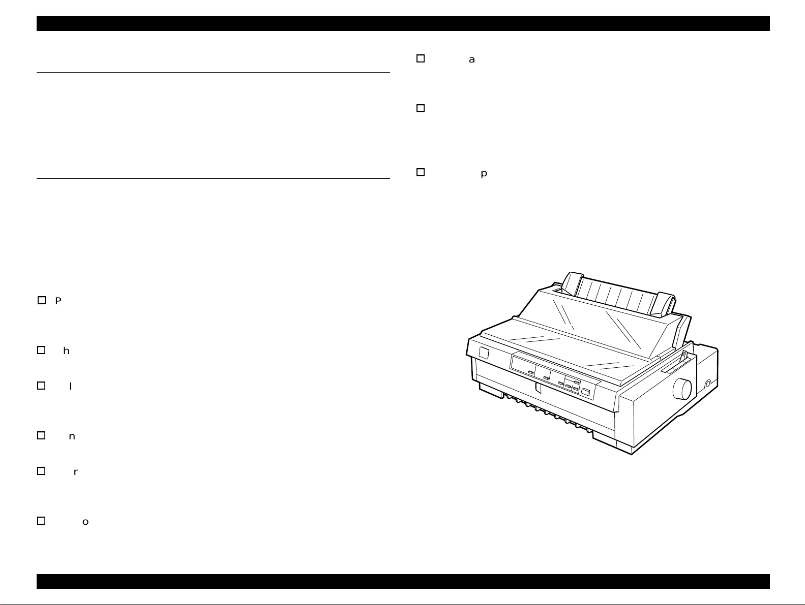
Product Description Overview 9
Figure 1-1. Exterior View of the FX-980
Page 10
FX-980 Revision A
1.2.2 Accessories
Table 1-1. Items Included with the Printer
Enclosed Items Quantity
User's manual 1
Driver diskette 1
Ribbon cartridge 1
Power supply cable (230 V Version) 1
Table 1-2. Consumable and Optional Items
Unit Description
Ribbon cartridge S015091-0036
Ribbon pack S010036-0036
High-capacity cut sheet feeder (bin 1) C806841 (EAI), C806842 (Non-EAI)
Second bin cut sheet feeder (bin 2) C806851 (EAI), C806852 (Non-EAI)
Pull tractor unit C800331 (EAI), C800332 (Non-EAI)
Roll paper holder #8310
32 KB intelligent serial I/F card C82307* / C82308*
Type-B Local Talk I/F card C82312*
Coax I/F card C82314*
Twinax I/F card C82315*
IEEE-1284 parallel I/F card C82345*
Type-B Ethernet I/F card for 10Base T/2 C82362*
Type-B Ethernet I/F card for 100Base T /
100Base TX
*1: When you use Ethernet interface card (C82363*), you need to attach the
optional interface card adapter (C82525*) to the interface card.
C82363*
*1
, C82364*,
Product Description Specifications 10
Page 11
FX-980 Revision A
1.3 Hardware Specifications
Print speed and printable columns: See the table below.
This section also contains information specific to the FX-980. For other
information, refer to the FX-2170 Service Manual.
1.3.1 Printing Specifications
Print method: Impact dot matrix
Number of pins: 18 pins
Print pin alignment: 9
Print pin diameter: 0.0114 inch (0.29 mm)
Color: Black
Print direction: Bi-directional with logic seeking
Resolution: See the table below:
Table 1-3. Resolution
Printing mode
Hifh speed draft 90 dpi 72 dpi No
Horizontal
density
× 2
Vertical density Adjacent dot print
Table 1-4. Print Speed and Printable Columns
Print Mode
High-speed draft
High-speed draft
condensed
Draft
Draft Condensed
Draft emphasized 10 cpi 80 190 165 142
NLQ
Character
Pitch
10 cpi
12 cpi
15 cpi
17 cpi
20 cpi
10 cpi
12 cpi
15 cpi
17 cpi
20 cpi
10 cpi
12 cpi
15 cpi
17 cpi
20 cpi
Printable
Columns
80
96
120
137
160
80
96
120
137
160
80
96
120
137
160
Print Speed (cps)
Normal Copy 1 Copy 2
506
569
569
560
506
380
455
380
325
380
95
114
94
81
95
439
455
494
483
379
330
396
285
282
330
82
99
71
70
82
337
404
426
322
329
284
341
285
244
284
71
85
31
60
71
Draft 120 dpi 72 dpi No
Draft condensed 240 dpi 72 dpi No
Draft emphasized 120 dpi 72 dpi Yes
NLQ 240 dpi 144 dpi No
Bit image
60, 72, 80, 90, or
120 dpi
120 or 240 dpi 72 dpi No
72 dpi Yes
NOTES:
1. When the power sup ply v ol tag e drops to the low er l im it, the printer stops printing and
then starts printing on that line again more slowly than before.
2. When the head temperature rises to the upper limit, the printer stops printing. When
the head temperature falls to the normal level, the printer start printing again more
slowly than before.
3. Copy 1: When the paper thieckess lever is set to 2 or 3.
4. Copy 2: When the paper thickness lever is set to 4 or more.
Product Description Hardware Specifications 11
Page 12

FX-980 Revision A
1.3.2 Paper Handling
Feeding method
Friction feed (front, rear)
Push tractor feed (front lever)
Push & Pull tractor feed (front, rear)
Pull tractor feed (front, rear, bottom)
Feed speed
Normal mode: 1/6 inch feed: 46 msec
Continuous feed: 0.127 MPS (m/second)
5.0 IPS (inches / second)
Copy mode: 1/6 inch feed: 68 msec
Continuous feed: 0.078 MPS (m/second)
3.1 IPS (inches/second)
Input data buffer: 0 Kbyte or 64 Kbyte
(depends on the default setting)
Product Description Hardware Specifications 12
Page 13
FX-980 Revision A
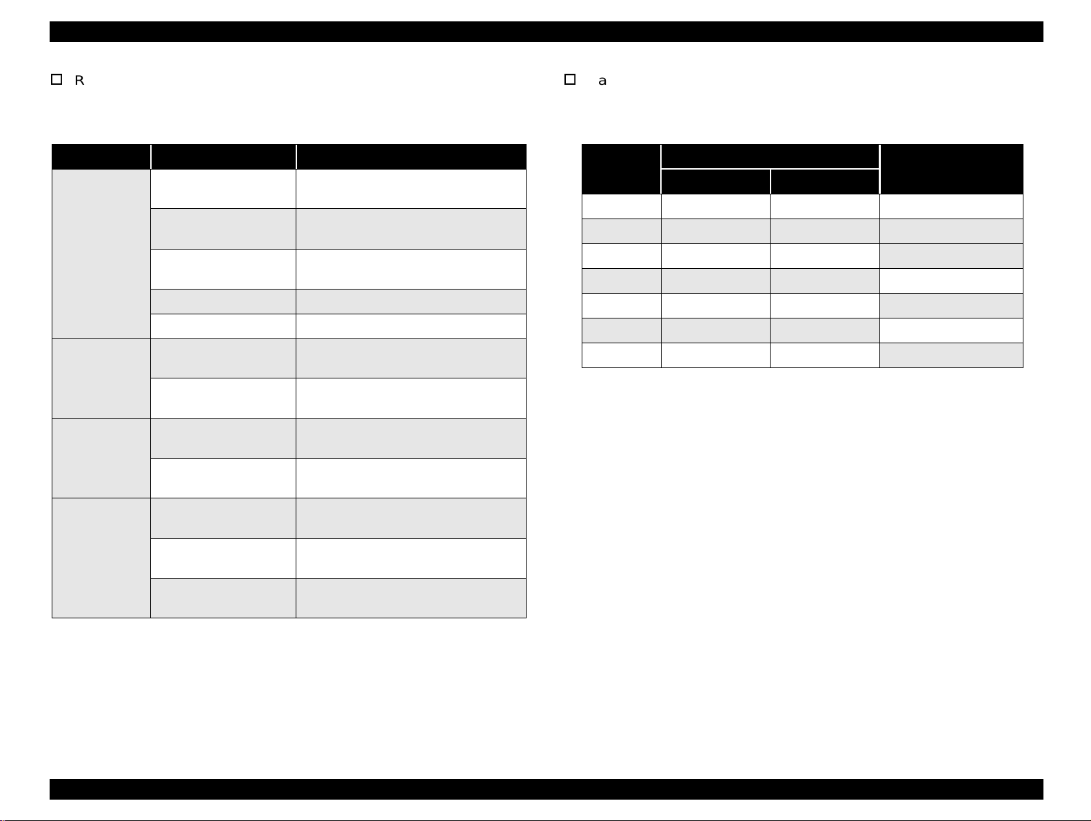
Release lever: See the following table.
Paper thickenss lever: See the following table.
Table 1-5. Release Lever Settings
Lever Position Paper path / Feeder Paper / Media
Manual insertion (front)
Manual insertion (rear)
Friction
CSF Bin 1
CSF Bin 2 Cut sheet (Single sheet)
Roll paper holder Roll paper
Push tractor feed (front)
Front tractor
Push & Pull tractor feed
(front)
Push tractor feed (rear)
Rear tractor
Push & Pull tractor feed
(rear)
Pull tractor feed (front)
Cut sheet
(Single sheet & Multipart), Card
Cut sheet (Single sheet & Multipart),
Card, Envelope
Cut sheet (Single sheet & Multipart),
Card, Envelops
Continuous paper (Single sheet &
Multipart), Continuous paper with labels
Continuous paper (Single sheet &
Multipart), Continuous paper with labels
Continuous paper
(Single sheet & Multipart)
Continuous paper
(Single sheet & Multipart)
Continuous paper (Single sheet &
Multipart), Continuous paper with labels
Table 1-6. Adjust Lever Setting Position
Setting
Position
0 0.0024 0.0043 over 0.06 up to 0.11
1 0.0043 0.0071 over 0.11 up to 0.18
2 0.0071 0.0079 over 0.18 up to 0.20
3 0.0079 0.0098 over 0.20 up to 0.25
4 0.0098 0.0126 over 0.25 up to 0.32
5 0.0126 0.0154 over 0.32 up to 0.39
6 0.0154 0.0185 over 0.39 up to 0.47
Paper Thickness (inch)
Paper Thickness (mm)
Minimum Maximum
Full release
Pull tractor feed (rear)
Pull tractor feed
(bottom)
Continuous paper
(Single sheet & Multipart)
Continuous paper (Single sheet &
Multipart), Continuous paper with labels
Product Description Hardware Specifications 13
Page 14

FX-980 Revision A
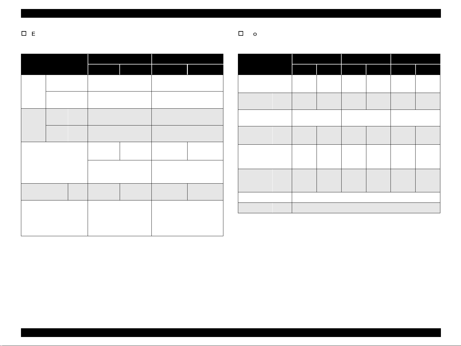
1.3.3 Paper Specifications
Cut sheet (multipart)
This section provides paper specifications for the FX-980.
Cut seet (single sheet, not multipart)
Table 1-7. Cut Sheet (Single Sheet, Not Multipart)
Front Entry Rear Entry
Minimum Maximum Minimum Maximum
Width
Length
Thickness
Weight
Quality
(inch)
(mm)
(inch)
(mm)
(inch)
(mm)
(g/m2)
(lb.)
3.9
100
5.8
148
0.0025
0.065
52
14
Plain paper, Recycled paper
crumpled
*1: Value whe n CSF bin 2 is used.
*2: Printing on recycled paper is available only under normal temperature and
humidity conditions.
10.1
257
14.3
364
0.0055
0.14
90
24
3.9 (7.2*1)
0.0025
0.065
52
14
*1
)
*1
)
100 (182
3.9 (8.3*1)
100 (210
*2
, Not curled, folded, or
0.0055
10.1
257
14.3
364
0.14
90
24
Table 1-8. Cut Sheet (Multipart)
Front Entry Rear Entry
Minimum Maximum Minimum Maximum
Width
Length
Copies 1 original + 5 copies 1 original + 5 copies
Total Thickness
Weight
(one sheet of
multipart)
Quality
Jointing
(inch)
(mm)
(inch)
(mm)
(inch)
(mm)
(g/m2)
(lb.)
3.9
100
5.8
148
0.0047
0.12
40
12
Plain paper, Recycled paper, Paper that is not curled,
folded, or crumpled.
Line glue at the top or one
side of form.
10.1
257
14.3
364
0.018
0.46
58
15
3.9
100
3.9
100
0.0047
0.12
40
12
Line glue at the top of form.
*1: Not available for the 2nd CSF.
*1
10.1
257
14.3
364
0.018
0.46
58
15
Product Description Hardware Specifications 14
Page 15
FX-980 Revision A
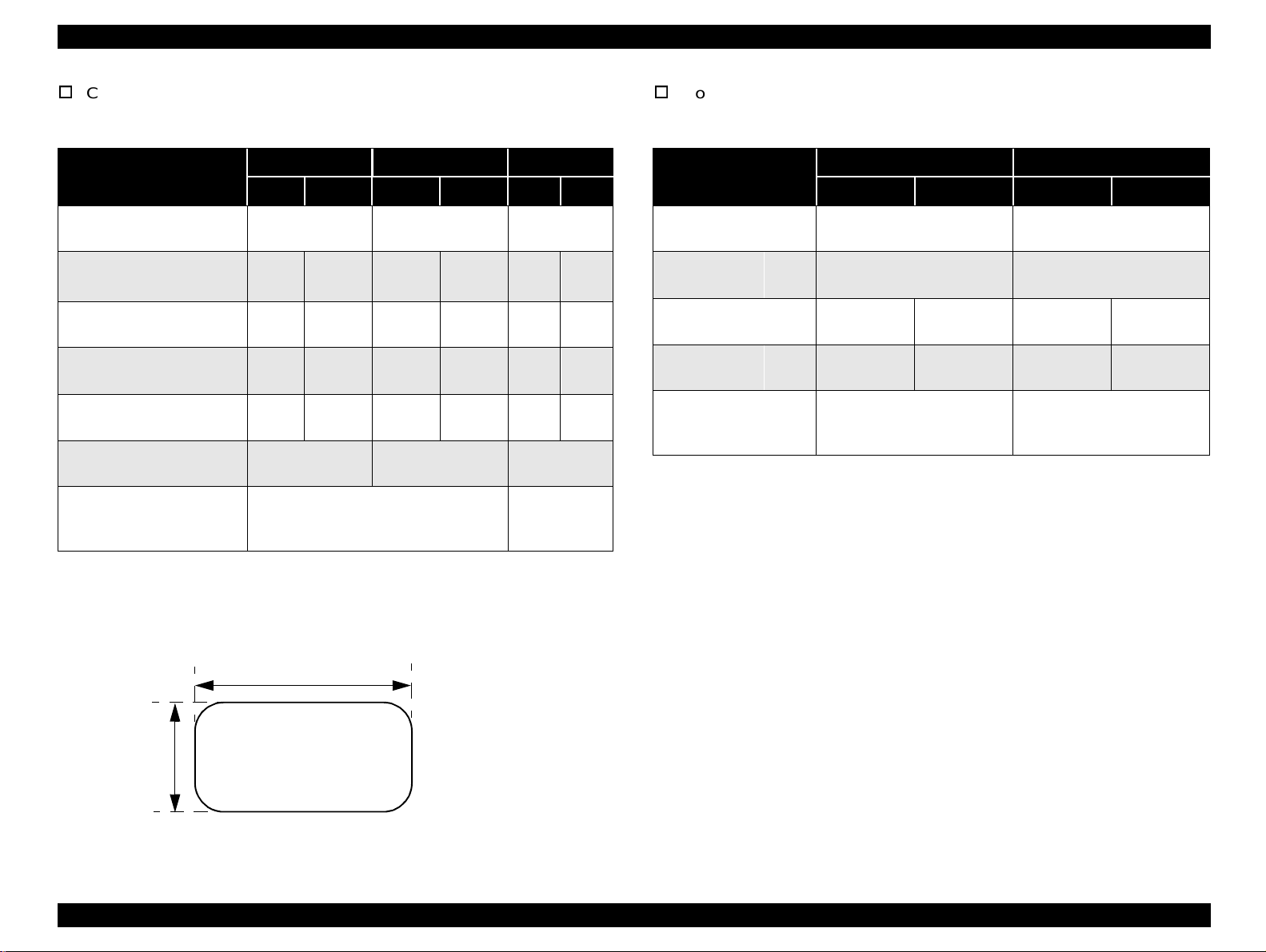
Envelope
Continuous paper (Single sheet and Multipart)
Table 1-9. Envelope
Front Entry Rear Entry
Minimum Maximum Minimum Maximum
Envelop
Width
(No. 6)
Length
Width
Envelop
(No. 10)
Length
Total Thickness
Weight
Quality - - -
(inch)
(mm)
(inch)
(mm)
(inch)
(mm)
(inch)
(mm)
(inch)
(mm)
(g/m2)
(lb.)
- - -
- - -
- - -
- - -
- - - - - -
- - -
- - - - - -
6.5
165
3.6
92
9.5
241
4.1
105
0.0063
0.16
The difference of thickness
at the printable area is within
0.0098 inch (0.25mm).
45
12
BOND paper, plain paper or
AIRMAIL
No glue at a flap
Not curled, not folded, not
crumpled
0.020
0.52
90
24
Table 1-10. Continuous Paper (Single sheet and Multipart)
Front Entry Rear Entry Bottom Entry
Min. Max. Min. Max. Min. Max.
Width
Length
(one page)
Copies
Total
Thickness
Weight
(not
multipart)
Weight
(one sheet
of multipart )
Quality Plain paper, Recycled paper, Carbonless multipart paper
Jointing Point glue or paper staple (both sides)
(inch)
(mm)
(inch)
(mm)4101.6
(inch)
(mm)
(g/m
(lb.)
(g/m2)
(lb.)
2
)
4
101.6
1 original + 5
0.0025
0.065
52
14
40
12
10.0
254
22
558.84101.622558.84101.622558.8
*1
copies
0.018
0.46
82
22
58
15
4
101.6
1 original + 5
0.0025
0.065
52
14
40
12
*1: When pull tractor is used, 1 original copy + 6 copies is available.
copies
10.0
254
0.018
0.46
82
22
58
15
4
101.6
1 original + 5
copies
0.0025
0.065
52
14
40
12
10.0
254
*1
0.018
0.46
82
22
58
15
NOTES:
1. Printing on envelope is available only under normal temperature and humidity
conditions.
2. Envelopes should be inserted from rear entrance only.
3. Set the longer side of envelope horizontally.
Product Description Hardware Specifications 15
Page 16
FX-980 Revision A
Coutnuous paper with labels
Roll paper
Table 1-11. Continuous Paper with Labels
Front Entry Bottom Entry Rear Entry
Min. Max. Min. Max. Min. Max.
Label size
Base sheet width
Base sheet length
(one page)
Base sheet
thickness
Total thickness
Label weight
Quality
(inch)
(mm)4101.6
(inch)
(mm)4101.622558.84101.6
(inch)
(mm)
(inch)
(mm)
(g/m2)
(lb.)
See the figure
below.
10.0
254
0.0028
0.07
0.0063
0.16
AVERY CONTINUOUS FORM
LABELS, AVERY MINI-LINE LABELS
or the same quality labels
0.0035
0.09
0.0075
0.19
64
17
NOTES:
1. Printing on labels is available only under normal temperature and humidity condition.
2. The base sheet of labels must be continuous paper.
3. Continuous paper with labels should be inserted from the front or bottom entrance.
2.5 inch (63.5 mm) min.
See the figure
below.
4
101.6
0.0028
0.07
0.0063
0.16
10.0
558.8
0.0035
0.09
0.0075
0.19
64
17
254
22
---
--- ---
--- ---
--- ---
---
---
Table 1-12. Roll Paper
Front Entry Rear Entry
Minimum Maximum Minimum Maximum
Width
Length
Thickness
Weight
Quality - - -
(inch)
(mm)
(inch)
(mm)
(inch)
(mm)
(g/m2)
(lb.)
- - -
- - - - - -
- - - - - -
- - - - - -
8.5
216
0.0028
0.07
52
14
Plain paper, Recycl ed p aper
Not curled, folded, or
crumpled
0.0035
0.09
82
22
15/16inch
(23.8 mm)
min.
Label
R 0.1 inch (2.5 mm) min.
Figure 1-2. Printable Area - Label
Product Description Hardware Specifications 16
Page 17
FX-980 Revision A
1.3.4 Ribbon Specifications
Type: Fabric
Color: Black
Ribbon Life: Approximately 7.5 million character s
(Draft 10 cpi, 14 dots / character)
Power consumption: Approximatel y 46 W
(ISO/IEC10561 Letter pattern)
Energy Star Compliant
Insulation resistance: 10 M
Dielectric strength: AC 1500 Vrms. 1 min.
Ω min.
(between AC line and chassis, DC 500 V)
(between AC line and chassis)
1.3.5 Electrical Specifications
The electrical specifications for the FX-980 are t he same as for the FX2170 except for the items belo w. For informati on on other items, see t he
FX-2170 Service Manual.
120 V Version
Input voltage range: AC 99 to 132 V
Power consumption: Approximately 46 W
(ISO/IEC10561 Letter pattern)
Energy Star Compliant
230 V version
Power consumption: Approximately 46 W
(ISO/IEC10561 Letter pattern)
Energy Star Compliant
UPS version
Rated voltage range: AC 100 to 120 V / AC 220 to 240 V
Input voltage range: AC 90 to 132 V / AC198 to 264 V
Rated frequency range: 50 to 60 Hz
Input frequency range: 49.5 to 60.5 Hz
Rated current: 1.1 A (max. 2.2 A / 0.6 A (max 1.1 A)
1.3.6 Reliability
Total print volume: 25 million lines (except printhead)
MTBF: 10000 POH (24% duty)
Printhead life: Approximately 300 million characters
1.3.7 Safety Approvals
120 V version
Safety standards: UL1950, CSA C22.2 No. 950
EMI: FCC part15 subpart B class B
CSA C108.8 class B
230 V version
Safety standards: EN60950 (VDE)
EMI: EN55022 (CISPR pub.22) class B
AS/NZS 3548 class B
UPS version
Safety standards: UL1950, CSA C22.2 No. 950,
EN60950 (VDE)
Product Description Hardware Specifications 17
Page 18

FX-980 Revision A
EMI: FCC part15 subpart B class B
CSA C108.8 class B
EN55022 (CISPR pub.22) class B
AS/NZS 3548 class B
1.3.8 CE Marking
230 V version & UPS version
Low voltage directive 73/23/EEC:EN60950
EMC Directive 89/336/EEC: EN55022 class B
EN61000-3-2
EN61000-3-3
EN50082-1
IEC801-2
IEC801-3
IEC801-4
1.3.9 Physical Specifications
Without options
- Dimensions: 528 mm(W) x 404 mm(D) x 236 mm(H)
- Weight: Approximately 11 kg
Including CSF bin 1
- Dimensions: 528 mm(W) x 471 mm(D) x 380 mm(H)
- Weight: Approximately 13 kg
Including CSF bin 1 & bin 2
- Dimensions: 528 mm(W) x 600 mm(D) x 411 mm(H)
- Weight: Aproximately 13.5 kg
Product Description Hardware Specifications 18
Page 19
FX-980 Revision A
1.4 Firmware Specifications
This section describes the firmware specifications for the FX-980.
1.4.1 Control Codes and Fonts
Control codes: ESC/P2 and IBM 2391 Plus Emulation
Character tables:
Standard version (13 character tables )
Italic table PC 860 (Portuguese)
PC 850 (Multilingual) PC 437 (US, Standard Europe)
PC 861 (Icelandic) PC 863 (Canadian-French)
PC 865 (Nordic) Abicomp
BRASCII Roman 8
ISO Latin 1 PC 858
ISO 8859-15
NLSP version (37 character tables)
Italic table PC437 (US, Standard Europe)
PC437 Greek PC850 (Multilingual)
PC852 (East Europe) PC853 (Turkish) PC855 (Cyrillic)
PC857 (Turkish) PC866 (Russian) PC869(Greek)
MAZOWIA (Poland) Code MJK (CSFR)
ISO 8859-7 (Latin/Greek)lSO Latin 1T (Turkish)
Bulgaria (Bulgarian) PC774 (LST 1283:1993)
Estonia (Estonia) ISO 8859-2 PC866 LAT. (Latvian)
PC866 UKR (Ukraina)PC860 (Portuguese)
PC861 (Icelandic) PC865 (Nordic) PC APTEC(Arabic)
PC708 (Arabic) PC720 (Arabic) PCAR864 (Arabic)
PC863 (Canadian-French) Abicomp
BRASCII Roman 8 ISO Latin 1
Hebrew7* Hebrew8* PC862 (Hebrew)*
PC 858 lSO 8859-15
International character set (13 countr ies)
U.S.A. France Germany
U.K. Denmark 1 Sweden
Italy Spain 1 Japan
Norway Denmark 2 Spain 2
Latin America
* The international and legal characters are these 12 codes:
23H, 24H, 40H, 5BH, 5CH, 5DH,
5EH, 60H, 7BH, 7CH, 7DH, 7EH
Typeface:
Bitmap fonts
EPSON Draft (10 cpi, 12 cpi, 15 cpi)
EPSON Roman (10 cpi, 12 cpi, 15 cpi, Proportional)
EPSON Sans Serif (10 cpi, 12 cpi, 15 cpi, Proportional)
Bar codes
EAN-13, EAN-8, Interleaved 2 of 5, UPC-A, UPC-E,
Code 39, Code 128, POSTNET
Character tables and available typefaces:
The following bitmap fonts are supported by all character tables
available for FX-980.
EPSON Draft, EPSON Roman, EPSON Sans Serif
NOTE:
ESC R command is effective on all the chracter tables.
* Not displayed in the Default setting mode.
Product Description Firmware Specifications 19
Page 20
FX-980 Revision A
1.4.2 Printable Area
Printable area for the FX-980 is the same as for the FX-2170 exept for
the point below:
Cut Sheet:
Left Margine
(Single/Multipart)
Right Margine
(Single/Multipart)
<FX-980>
3 mm or more (Paper width is
27 mm or more (Paper width is ≤ 257 mm)
<FX-980>
3 mm or more (Paper width is
27 mm or more (Paper width is
216 mm)
≤
216 mm)
≤
257 mm)
≤
1.4.3 Interface Specifications
This printer provides bi-directional 8-bit parallel interface, serial
interface, and Type-B interface ooptional interface card slot as
standard.
For information that is not covered in this section, refer to the FX-2170
Service Manual.
1.4.3.1 Parallel Interface (Forward Channel)
Transmission mode: IEEE-1284 compatibil ity mode
Signal level: TTL compatible
IEEE-1284 level 1 device)
Pin assignment: The pin assignment (forward channel) is
the same as for the FX-2170 except for
the function of the pins below:
Pin No. Function
18 <FX-980> This line is pulled up to +5 V through 3.9 k Ω resistor.
35 <FX-980> This line is pulled up to +5 V through 1.0 k Ω resistor.
BUSY signal is active (HIGH level) under the conditions below:
In addition to the conditions given in the FX-2170 Service Manual,
If -ERROR or PE signal is active (low level, high level,
respectively).
-ERROR signal is active (low level) under the conditions below:
If there is a paper-out error.
If there is a release lever error.
If there is a cover open error.
PE signal is active (high level) under the condition below:
If therer is a paper-out error.
Product Description Firmware Specifications 20
Page 21
FX-980 Revision A
1.4.3.2 Parallel Interface (Reverse Channel)
Transmission mode: 8 bit parallel, IEEE-1284 nibble mode
Synchronization: Refer to the IEEE-1284 specification
Handshaking: Refer to the IEEE-1284 specification
Signal level: IEEE-1284 level 1 device
Data transmission timing: Refer to the IEEE-1284 specification
Device ID:
[00H][4DH]
MFG: EPSON;
CMD: ESCPL2,PRPXL24,BDC;
MDL: FX-980;
CLS: PRINTER;
DES: EPSON[SP]FX-980;
Pin assignment: The pin assignment (reverse channel) is
the same as for the FX-2170 except for
the functions of the pins below:
1.4.3.3 Serial Interface
Synchronization: Asychronous
Signal level: EIA-233D
MARK (logical 1): -3 V to -25V
SPAC:E (logical 0): +3 V to +25V
Word length: Start bit: 1 bit
Data bit: 8 bit
Parity biy: Odd, Even, Non, Ignore
Stop bit: 1 bit or more
Baud rate: 2400, 4800, 9600, or 19200 bps
Handshaking: DTR signal and XON/SOFF
Error handling: When a parity error is detected, the
received byte is changed to a “*”
character code. Overrun error and
framing error are ignored.
Connector: 25 pin subminiature D-shell connector
(female)
Pin No. Function
18 <FX-980> This line is pulled up to +5 V through 3.9 k Ω resistor.
35 <FX-980> This line is pulled up to +5 V through 1.0 k Ω resistor.
Connecotr pin assgnment and signals:
See Table 1-13 on the following page.
Product Description Firmware Specifications 21
Page 22

FX-980 Revision A
Table 1-13.
Connector Pin Assignment and Signals for Serial I/F
Pin
No.
other NC - Not used. Not connected.
*1: In/Out refers to the direction of signal flow from the printer’s point of view/.
Signal Name
2 TXD Out Transmits data.
20 DTR Out
11 REV Out Connected directly to the DTR signal.
4 RTS Out
3 RXD In Receives data.
7 Signal GND - Signal GND.
1 Chassis GND - Chassis GND.
In/
Out
*1
Indicates that the printer is ready to
receive data or not.
Request to send. Always SPACE level
when the printer is powered on. Pulled
up to +12 V via 4.7 K Ω resistor.
Functional Description
Product Description Firmware Specifications 22
Page 23

FX-980 Revision A
1.5 Operation Instruction
Operations at power on
This section provides information on the FX-980 control panel buttons,
LED, and operations. Since the layout and functions of t he control panel
are mostly common to those of FX-2170, this section only provides the
information that is speci fic to FX-980. For other information, see FX2170 Service Manual.
Draft
Roman
Sans serif
Font
10cpi
12cpi
15cpi
17cpi
20cpi
PS
Pitch
Tear O ff
Bin 1
Bin 2
Card
: L E D O n , : L E D B lin k s ,
T ear O ff/B in
Micro Adjust
LF/FF
: L E D O ff
Pause
3se c.
L oad /E ject
Paper O ut
O perate
Figure 1-3. Control Panel
Turning on the printer while pressing panel buttons executes the
functions shown in the following table.
Table 1-14. Operations at Power On
No. Buttons Function
1 Load / Eject NLQ self test
2 LF / FF Draft self test
3Pitch
4 Load / Eject & LF / FF Data dump
5 Font & Tear Off / Bin EEPROM clear
6 Tear Off / Bin & LF / FF
7 Pause Bi-d adjustment
8 Font
Default setting (See the following table for
the setting menu.)
Clear EEPROM for Driving Line count for
ribbon change timing
Alternates copy mode on and off.
When “off” is selected, beeps one time.
When “on” is selected, beeps two times.
The setting is saved to non-volatile
memory.
9 The others Not available.
Product Description Operation Instruction 23
Page 24

FX-980 Revision A
Table 1-15. Default Setting Menu
Item Setting / Value
Standard version / NLSP version: See Section 1.3 for
Character table
International character set
for Italic table
Page length for front tractor
Page length for rear tractor
Print direction
Software
I/F mode
Auto I/F wait time
Input buffer
Baud rate
Parity
Skip over perforation On,
the character tables available.
PC437
Italic U.S.A.
Italic Denmark 1, Italic Sweden, Italic Italy,
Italic Spain 1
3 inch, 3.5 in ch , 4 in ch, 5.5 inch, 6 in ch, 7 inch, 8 inch ,
8.5 inch,
3 inch, 3.5 in ch , 4 in ch, 5.5 inch, 6 in ch, 7 inch, 8 inch ,
8.5 inch,
Bi-d.
ESC-P2
Auto
10 sec.
On
19200BPS
None
, Italic France, Italic Germany, Italic U.K.,
11 inch
11 inch
, Uni-d.
, IBM 2380 Plus
, Parallel, Serial, Optional
, 30 sec.
, Off
, Odd, Even, Ignore
Off
, 70/6 inch, 12 inch, 14 inch, 17 inch
, 70/6 inch, 12 inch, 14 inch, 17 inch
, 9600BPS, 4800BPS, 2400 BPS
*1
Status code indicated by the LEDs
Table 1-16. Status code indicated by the LEDs
Pause
Pause On --- --- --- --Paper out On On --- --- --Paper jam On Blink --- --- --Head hot Blink --- --- --- --Cover Open On --- --- --- --Micro Adjust Blink --- --- --- --Tear off --- --- * --- --Bin selection --- --- * --- --Pitch selection --- --- --- * --Font selection --- --- --- --- *
Fatal error Blink Blink Blink Blink Blink
*: Varies depending on the selection. (See Figure 1-2.)
Buzzer
Paper
Out
Tear Off /
Bin
Condensed Font
Auto tear off On,
Auto line feed On,
Auto CR (IBM 2380 Plus)
0 slash On,
*2
On,
Off
Off
Off
Off
Paper out error: Beeper sounds (...) *
Cover Open error: Beeper sounds (...) *
Release lever operation error: Beeper sounds (- - - - -)*
Illegal panel operation: Beeper sounds (.)*
* The description (.) and (-) shows how the beeper sounds.
Buzzer
IBM character table
*1: Setings with bold weight meas the standard factory settings.
*2: This setting is effective when IBM Plus 2380 emulation is selected.
On
, Off
Table2
, Table 1
(.): Beeper sounds approx.100 ms and interval is approx. 100 ms.
(-): Beeper sounds approx.500 ms and interval is approx. 100 ms.
Product Description Operation Instruction 24
Page 25

FX-980 Revision A
1.5.1 Errors
Paper out:
When the printer fails to feed a sheet, it goes a paper out error.
Release lever error:
When release lever position is wrong, it goes a release lever error.
Cover Open error:
When the printer’s cover is opened, it goes a release lever error.
Fatal error:
Carriage control error and Power supply voltage error
1.5.2 Bi-directional Adjustment Function
Bi-directional adjustment can be made for the following three modes.
High-speed draft mode
Draft mode
NLQ mode
Product Description Operation Instruction 25
Page 26

FX-980 Revision A
1.5.3 EEPROM Initialization
Areas reset by EEPROM clear operation (described in Section 1.3.1)
are as shown in the following tables:
Table 1-17. Initialization Area for EEPROM (1/2)
No. Item Factory setting
1 Character table selection PC437
2 Page length (rear tractor) 11 inch
3 Page length (front tractor) 11 inch
4 Page length (CSF Bin 1) 22 inch
5 Page length (CSF Bin 2) 22 inch
6 TOF adjustment value (rear tractor) 8.5 mm
7 TOF adjustment value (front tractor) 8.5 mm
8 TOF adjustment value (CSF Bin 1) 8.5 mm
9 TOF adjustment value (CSF Bin 2) 8.5 mm
TOF adjustment value
10
(rear manual insertion)
TOF adjustment value
11
(front manual insertion)
12 Bottom margin (rear tractor) 11 inch
13 Bottom margin (front tractor) 11 inch
14 Font selection Roman
15 Pitch selection 10 cpi
16 Copy mode Off
17 Print direct ion setting Bi-D
18 I/F mode selection Auto
19 Auto I/F wait time setting 10 sec
8.5 mm
8.5 mm
Table 1-18. Initialization Area for EERPOM (2/2)
No. Item Factory setting
20 Auto line feed Off
21 Auto tear off Off
21 Skip over perforation Off
22 High speed draft On
23 Input buffer On
24 Software ESC/P
25 0 slash Off
26 Buzzer On
27 Roll paper Off
28 Auto CR (IBM) Off
29 Tear-off adjustment value 0 clear
30 Manual insertion wait time 2 or 3 sec.
31 Tear-off wait time 3 sec.
32 Serial baud rate 19200
33 Serial parity None
34 Paper width measure On
35 TOF minimum value 4.2 mm
36 I/F timing data BUSY
37 Paper edge length 0 clear
38 Page length (rear manual insertion) 22 inch
39 Page length (front manual insertion) 22 inch
Product Description Operation Instruction 26
Page 27

FX-980 Revision A
5
1.6 Main Components
The main components for the FX-980 are as fol lows. They are designed
for easy disassembly and repair work.
C276 Main Board
C166 PSB/PSE / C244 PSH
C276 PNL Board
Printer Mechanism
Housing (upper and lower cases)
1.6.1 C276 Main Board
The C276 Main Board consists of the TMP96C141 CPU, an E05B50
gate array, a PS-RAM, a PROM, and so on.
CN17
CN3
CN4
CN5
CN6
CN8
CN7
CN9
Figure 1-4. C276 Main Board Assembly
CN18
CN10
CN11
CN16 CN12 CN13
IC 1 5
IC 5
IC 1
IC 3
CR1
IC 2
CN14
CN1
1.6.2 C276 PNL Board
This board function is the control panel for the FX-98 0. It consis ts of the
power switch, six buttons, and the indicator LEDs.
LE DLE DLE DLE DLE D
SWSWSWSWSW
Figure 1-5. C276 PNL Board Assembly
Product Description Main Components 27
Page 28

OPERATING PRINCIPLES
Page 29

FX-980 Revision A
2.1 Printer Mechanism Operations
See the LQ-2070 Service Manual.
2.2 Power Supply Operation
See the LQ-2070 Service Manual.
Operating Principles Printer Mechanism Operations 29
Page 30

FX-980 Revision A
2.3 Control Circuit
The control circuit consists of the C276 Main Boa rd assembly and C276
PNL Board. This section describes t he major components and explains
how the boards work.
2.3.1 Overview of the Control Circuit Operation
The printer's control circuit includes a TMP96C141 CPU that runs at
19.66 MHz, an E05B50 gate array, a 1M bit PS-RAM (8-bit bus, less
than 100ns), a 4M bit PROM (8-bit bus, less than 120ns), and other
circuits. It oversees control of all the components in the printer. The
following chart shows you a block diagram of the control circuit.
Type B I/F
P a r a lle l I/ F
Panel LE D
Power SW
PSC
PW DN
P/ S
Unit
5V
GL
35V
4M EP-R O M
IC 5
(M ASK ROM )
IC 1
G a te A r ra y
E05B 50
IC 9
CR Drv.
SLA7024M
IC 8
EEPRO M
IC 1 5
R e s t IC
IC 1 2
PF Drv.
A2917S E B
IC 3
PSRAM
CSF Drv.
IC 2
CPU
TM P96C 141
CSF
Detector
Q2 - Q19
H ead D rv.
H ead T em p.
Detector
+35V V oltage
Detector
PE -R ear
Detector
PE -Front
Detector
P-W idth (Top)
Detector
Hom e
Detector
R elease 1
R elease 2
Lever
Detector
PG 1, PG 2
Lever
Detector
: D a ta B u s
: A ddress Bus
Figure 2-1. Control Circuit Block Diagram
Operating Principles Control Circuit 30
Page 31

FX-980 Revision A
The following figure shows the data flow from the host compute r to the
printhead. Data sent fr om the host comput er is conve rt ed to i mage dat a
and transmitted to the printhead through the gate array.
Serial I/F
O p tio n I/F
P a ra lle l I/F
Host
C om puter
IC 7
Tranceiver
G a te A r ra y
E05B50
D a ta la tc h
a n d
data output
CPU
TM P96C 141
P rin t d a ta
conversion 1
P rin t d a ta
conversion 2
Im age data
transfer
RAM
In p u t
B u ffe r
Line E dit
B u ffe r
Im age
B u ffe r
The table below lists the each function of the main components of the
C276 Main Board.
Table 2-1. Functions of the Main Board
IC Location Function
Receives data from the host computer and sends it
to the input buffer in RAM (under interrupt
CPU IC 2
Gate Array IC 1
processing control). E x tends the input data held in
the buffer to create image data. Loads this image
data to the image buffer in RAM. Transfers the
image data to the printhead driver circuit.
Controls the functions below:
• Controls output data from the internal block
• Memory management
• Address latch of the address/data bus from the
CPU
• Clock control unit
• Bit manipulation
• Interface control
• Expanded parallel port
• Printhead control
• Motor control
An electrically writable and erasable ROM used to
EEPROM IC 8
Printhead drive
circuit
hold such information as the TOF position and
bidirectional adjustment value.
The ROM contains the program that runs the CPU
ROM IC 5
Figure 2-2. Data Flow
RAM IC 3
and holds the character design (also called the
character generator).
The RAM contains the CPU working area and the
buffers.
SLA7024M IC 9 Driver circuit for the CR motor.
A2917SEB IC 12 Driver circuit for the PF motor.
Operating Principles Control Circuit 31
Page 32

FX-980 Revision A
+5V
2
IN
IC 15 Reset
4
GND
5
OUT2
61
23
/R S T
/R S T
IC 2 G .A .
IC 1 C P U
2.3.2 System Reset Circuit
Control circuits IC1 and IC2 are initialized when a /RESET si gnal (LOW
level) is output from port 5 (VOUT) of IC15. IC15 monitors the +5 V line
on port 2, and resets under the following condit ions:
1. When the power supply is turned on, a /RESET signal is output.
/RESET is canceled when the +5 V line goes up to 4.2 V, and then
100 ms passes.
2. When the +5 V line goes below +4.2 V, a /RESET signal is output.
/RESET is canceled when the +5 V line goes back up to 4.2 V and
then 100 ms passes.
Figure 2-3. Reset Circuit
(v )
5
4
100m s
RESET
3
2
1
Power O n
VOUT (RESET)
Figure 2-4. Reset Signal Output Timing
100m s
RESET
VCC (+5V line)
Operating Principles Control Circuit 32
Page 33

FX-980 Revision A
1
2.3.3 Printhead Driver Circuit
The standard voltage for the A/D conv erter is made in ZD1 and input to
CPU port 78. Based on this standard voltage, the A/D converter in the
CPU operates. Port 74 monitors the +35 V line between R70 and R71 to
determine the printhead driver pulse width . Using the monitored
voltage, the CPU converts the voltage to a digital value and decides the
printhead driver pulse width, and then trans ports the data to the gate
array via CPU ports 15 and 19. Based on the monitored voltage, the
CPU decides the printing interval. Port 73 monitors the printhead
temperature to protect th e printhead. If the t emperature exceeds 107
° F), printing is stopped.
(225
Printhead
Printhead D rive Transistor Q 2 - Q 19
Printhead D rive Signal
31
32
Address
D ata Line
CPU
19
15
Gate
Array
74
73
7879
ZD1
+35V
C2
+35V
+
+35V
+35V
HTMP
R72
° C
R70
R71
2.3.4 CR Motor Driver Circuit
The CR motor driver circuit is shown below.
IC 2 C P U
CN1
PG00
PG01
PG02
PG03
68
67
5
6
17
16
6
/IN A
5
/IN -A
/IN B
/IN -B
IC9 SLA2024M
Figure 2-6. CR Motor Driver Circuit
The carriage motor driver circuit controls the CR motor, using an
open-loop, constant drive arrangement. 2-2 and 1-2 phases excite the
motor. One step of the 2-2 phase switching system corresponds to 2
steps of the 1-2 phase switching system. Ports 1, 8, 11, and 18 of the
SLA7024M are used to change the excitation phase, depending on the
selected print mode. Table 2-2 on the following page describes the
motor driver modes.
The SLA7024M (IC9) CR motor driver circuit detects and regulates the
amount of current flowing in the carriage mot or coil . The curr ent flowi ng
through the coil varies, depending on the speed of the CR motor. The
CPU sets the amount of current via the Address / Data line. Signals are
sent via ports 3 (RFA) and 14 (RFB) to the SLA7024M. The SLA7024M
sets the coil current, depending on the CR speed.
8
A
/A
18
B
11
/B
1
1
2
3
4
C42
Figure 2-5. Printhead Drive Circuit
Operating Principles Control Circuit 33
Page 34

FX-980 Revision A
Table 2-2. CR Motor Driver Modes
Speed Mode
8/3 507 6080 2-2 HN H: High speed draft
5/2 475 5700 2-2 HN (12 cpi)
44/19 440 5280 2-2 HC-1
2 380 4560 2-2 HC-1 (12cpi), DN, HN (15 cpi)
16/9 338 4053 2-2 HC-2, H cold mode, HC-2 (12cpi)
33/19 330 3960 2-2 DC-1, HC-1 (15 cpi), HN (17 cpi)
3/2 285 3420 2-2
4/3 253 6080 1-2
1 190 4560 1-2
33/38 165 3960 1-2 LC-1, HC-1P (15 cpi), HP (17 cpi)
3/4 143 3420 1-2 LC-2, LC-2P (15 cpi)
Print Speed
(CPS)
Drive
Frequency
(PPS)
Excitation
Phase
Application (See the Remarks.) Remarks
D: Draft
L: LQ
B: Bit image
R: Raster graphics
N: Normal
C-1: Copy 1
C-2: Copy 2
HP, H (12 cpi) cold mode, DC-2, HC-2, (15
cpi), HC-1 (17 cpi)
HP (12 cpi), D cold mode, H (15 cpi) cold
mode, HN (20 cpi)
HC-1P, HC-2P, HC-1P (12 cpi), HC-2P (12
cpi), DP, LN, HP (15 cpi), HC-2 (17 cpi), H
(17 cpi) cold mode, HC-1 (20 cpi), HC-2
(20 cpi)
P: Power down
CP: Copy Power down
2/3 127 3040 1-2 L cold mode, HC-1P (17 cpi), LN (15 cpi)
1/2 95 2280 1-2
33/76 82 1980 1-2 LC-1 (17 cpi), LC-1 (20 cpi)
57/152 71 1710 1-2 LC-2 (17 cpi), LC-2 (20 cpi)
33/152 41 990 1-2 LC1P, LC2P
77/456 770 1-2 LC1PP (17 cpi), LC2PP (17 cpi)
LP, HC-2 (17 cpi), LC-1 (15 cpi), LC-2 (15
cpi), LN (17 cpi), LN (20 cpi)
Operating Principles Control Circuit 34
Page 35

FX-980 Revision A
2.3.5 PF Motor Driver Circuit
The figure below shows the PF motor driver circuit.
IC 2 C P U
9
PP61
10
PP60
61
P27
2
IC 1 G .A .
PG10
PG11
68PFI1
67PFI2
5
6
IC 11 74LS32
1
23
24
IC 12 A2917S EB
Figure 2-7. PF Motor Driver Circuit
IC 12 driver receives phase data from the CPU and gate array. The PF
driver current is controlled by the 74LS32 using port 61 (P27) of IC2.
These controlled drive currents are output to ports 2 (I10), 1 (I11), 23
(I20), and 24 (I21) of the A2917SEB.
I1 0
I1 1
I2 0
I2 1
43
26
PH1
PH2
A
/A
B
/B
18
21
CN10
6
1
3
3
2
4
2.3.6 EEPROM Control Circuit
The EEPROM is nonvolatile memory that stores information even if the
printer power is off. The figure below shows the EEPROM control
circuit.
IC 2
9
10
11
12
CPU
P70
P71
P72
P73
Figure 2-8. EEPROM Control Circuit
The EEPROM is controlled by CPU ports 9 (P70), 10 (P71), 11 (P72),
and 12 (P73). Port 11 is the data output line used to save the
information to the EEPROM, and port 12 is the data input line used to
read the saved data from the EEPROM. Port 70 is the chip select line,
and port 71 is the clock timing line. When the PWDN signal (power
down) is detected on port 20 (INTO), the CPU writes the necessar y data
to the EEPROM before the +5 V line drops to 4.75 V.
1
CS
2
SK
3
DI
4
DO
IC 8
EEPRO M
Operating Principles Control Circuit 35
Page 36

FX-980 Revision A
2.3.7 Sensor Circuit
The CPU detects conditions of the following sensors: home posit ion
(HP) sensor, release sensors 1 and 2, pl aten gap (PG) sensors 1 and 2,
rear and front paper end (PE) sensors, paper width (PW) senso r, and
cover open sensor.
Two types of sensors are used in this printer. Release sens ors 1 and 2,
the PG sensors 1 and 2, the front PE sensor, and the cover open
sensor are momentary switches.
The other type of sensor i s used for the HP sensor, rea r PE sensor, and
PW sensor, which are photo diode switches. The HP sensor detec ts CR
home position when the photo diode rays are cut off by the printhead.
+5V
Rear PE
S ensor
Front P E
Sensor
PW S ensor
+5V
+5V
75
70
68
P40
P36
AN2
The rear PE sensor detects that paper has been loaded when the photo
diode rays are cut off by the sensor plate, which is included in the rear
PE sensor. The PW sensor, used for paper width measurement and
paper loading positioning, detects the paper edge by comparing the
measured voltage with standard voltage, which was measured during
the power on sequence.
Additionally, as mentioned on the page 2-24 (LQ-2070 Servi ce Manual),
the +35 V line and head temperatures are monitored to set the pulse
length of the head driver signal.
+5V
+5V
HP Sensor
R elease
Sensor 2
R elease
Sensor 1
PG Sensor 1
PG Sensor 2
C over O pen
Sensor
CPU
P53
P32
P33
P34
P35
IN T 7
76
64
65
66
67
18
+5V
+5V
+5V
+5V
+5V
+5V
+5V
Figure 2-9. Sensor Circuit
Operating Principles Control Circuit 36
Page 37

DISASSEMBLY AND ASSEMBLY
Page 38

FX-980 Revision A
3.1 Overview
This chapter provides disassembling / assembling procedures for the
FX-980. Since the most procedures are common to the FX-2170, this
chapter only includes information that is specific to the FX-980.
3.2 Printer Disassembly and Assembly
The assembly procedures to be explained for the FX-980 are as listed
below. (Note the heading numbers and figure numbers used in the FX2170 Service Manual are applied to this chapter.)
Section 3.2.10 Removing the Printer Mechanism
Section 3.2.10.3 Removing the Right Frame Assembly
Section 3.2.10.5 Removing the Left Frame Assembly
Section 3.2.11 Removing the C276 Main Board Assembly
For other disassembly procedures, see the FX-2170 Service Manual.
Disassembly and Assembly Overview 38
Page 39

FX-980 Revision A
CHECK
PO INT
3.2.10 Removing the Printer Mechanism
Changed point:
The printer mechanism and the connector cover are connected with
a screw, so the operation for removing the screw (step 3) is added.
1. Remove the rear / front edge guide assembly, front cover, paper
eject assembly, rear / front tractor unit s, and printer cover (see
Section 3.2.1).
2. Remove the panel board assembly (see Section 3.2.2) and upper
housing assembly (see Section 3.2.7).
3. Remove the screw securing the upper connector cover located
above the option I/F slot to the printer mechanism.
4. Remove 4 printer mechanism mounting screws.
5. Disconnect the following connectors on the C276 Main Board
assembly:
CN4 (3-pin, white) CN5 (3-pin, black)
CN6 (2-pin, white) CN7 (4-pin white FFC)
CN8 (18-pin, white FFC) CN9 (16-pin, white FFC)
CN10 (4-pin, blue) CN11 (5-pin, blue)
CN12 (2-pin, blue) CN13 (4-pin, black)
CN16 (2-pin, yellow)
Printer Mechanism Mounting Screws
NOTE:Disconnect the cables for CN10 and CN11 after
releasing the connector lock by pulling up.
6. Remove the printer mechanism.
ADJUSTMENT
REQUIRED
Perform the Bi-directional adjustment and TPE reset.
Refer to Chapter 4.
Figure 3-17. Removing the Printer Mechanism
Notice the connection for cables CN10 and CN11
and align the red colored cable to the pin 1 of the
connector.
The tightening torque for the printer mechanism
mounting screw = 0.98 Nm - 1.18 Nm (10 - 12 Kg cm)
Disassembly and Assembly Printer Disassembly and Assembly 39
Page 40

FX-980 Revision A
ADJUSTMENT
REQUIRED
y
3.2.10.3 Removing the Right Frame Assembly
Changed points:
Step 4 for removing the release sensor 1 is added. (See Figure
3-21 for its location.) In the FX-2170, the release sensor 1 is on
the left frame.
The Hexagon nut standard M7 (step 5) is used instead of the
FX-2170’s standard M4.
1. Remove the rear / front edge guide assembly, front cover, paper
eject assembly, rear / front tractor unit , and the printer cover (see
Section 3.2.1).
2. Remove the panel board (see Section 3.2.2) and upper housing
assemblies (see Section 3.2.7).
3. Remove the printer mechanism (see Section 3.2.1 0 in t his manual) ,
CR motor assembly (see Section 3.2.9), PF motor (see Section
3.2.10.1), and PG sensor assembly (see Section 3.2.10.2).
4. Remove the release lever sensor 1 from the inner side of the ri ght
sub frame.
5. Remove the hexagon nut (standard M7) securing the gap
adjustment lever. Then, remove the gap adjust lever from the right
frame assembly.
6. Remove 2 CBS screws (3
7. Remove 3 CBS screws (3
× 6, F/Zn) securing the platen cover.
× 6, F/Zn) securing the right frame
assembly at the positions illustrated.
8. Remove the right frame assembly.
R elease Lever S ensor 1
CBS Screw (3 x6) Securing th e R ight Fram e Assem bl
Figure 3-21. Removing the Right Frame Assembly
Perform the platen gap adjustment and the Bidirectional adjustment. (Refer to Chapter 4.)
Disassembly and Assembly Printer Disassembly and Assembly 40
Page 41

FX-980 Revision A
CHECK
PO INT
y
3.2.10.5 Removing the Left Frame Assembly
Changed points:
Step 6
There are only two connectors to be disconnected instead of
FX-2170’s three, because the FX-980 has only one release
lever sensor on the left frame.
The Hexagon nut standard M7 is used instead of the FX-2170’s
standard M4.
1. Remove the rear / front edge guide assembly, front cover, paper
eject assembly, rear / front tractor unit , and the printer cover.
2. Remove the panel board assembly (see Section 3.2.2), upper
housing assemblies (see Section 3.2.7), and then remove the
printer mechanism (see Section 3.2.10 in this manual).
3. Remove 2 CBS screws (3
4. Remove the hexagon nut (standard M7) secur ing the front CR gui de
and left frame.
× 6, F/Zn) securing the platen cover.
Platen C over
CBS Screws (3 X 6 F/Zn ) Securing the Left Fram e A ssem bl
C.B.S Screw (3 X 6 F/Zn)
H exagon N ut (S tandard, M 7)
Figure 3-26. Removing the Left Frame Assembly
P laten
Left Fram e A ssem bly
5. Remove 4 CBS screws (3
× 6, F/Zn) securing the left frame
assembly.
6. Disconnect the connector cable (blue) f rom the release lever
sensor, and then disconnect the connector cable from the HP
sensor.
7. Remove the left frame assembly.
ADJUSTMENT
REQUIRED
Adjust the platen gap and Bi-D adjustment. (Refer to
Chapter 5.)
R elease Lever S ensor 2 (B lue connector)
Figure 3-27. Release Lever Sensor
The tightening torque for the CBS screw (3
= 0.78 to 0.98 Nm (8 - 10 Kgf - cm)
The tightening torque for the hexagon nut (standard
M7) = 1.18 - 1.37Nm (12 - 14 Kgf - cm)
Disassembly and Assembly Printer Disassembly and Assembly 41
×
6, F/Zn)
Page 42

FX-980 Revision A
ADJUSTMENT
REQUIRED
r
3.2.11 Removing the C276 Main Board Assembly
Changed points:
The C276 Main Board in the FX-980 can be removed without
removing the I/F cage, so the operation for removing th e cage is
eliminated.
Step 5 (I/F cover removal) is added. (This operation is not new
but omitted in the FX-2170 Service Manual.)
1. Remove the rear / front edge guide assembly, front cover, paper
eject assembly, rear / front tractor unit , and prin ter cover (see
Section 3.2.1).
2. Remove the panel board (see Section 3.2.2).
3. Disconnect the following connectors fro m the C276 Main Board
assembly.
CN3 (10-pin, white) CN4 (3-pin, white)
CN5 (3-pin, black) CN6 (2-pin, white)
CN7 (4-pin white FFC) CN8 (18-pin, white FFC)
CN9 (16-pin, white FFC) CN10 (4-pin, blue)
CN11 (5-pin, blue) CN12 (2-pin, blue)
CN13 (4-pin, black) CN15 (22-pin, FFC)
CN16 (2-pin, yellow)
5. Remove the 2 screws securing the I/F cover and remove the I/F
cover.
6. Remove the 5 CBB screws (3 x 12, F/Zn) and 1 CBC lamitite screw
(3 x 8, F/Zn) securing the C276 Main Board assembly to the lower
housing assembly.
7. Remove the C276 Main Board.
C 276 M AIN Board A ssem bly
Lam itite Screw
I/F C o v e
4. Remove the 3 CBS screws (3 x 12, F/Zn) securing the upper
Disassembly and Assembly Printer Disassembly and Assembly 42
NOTE:Disconnect the cables for CN10 and CN11 after
releasing the connector lock.
NOTE:Disconnect the cable for CN3 by pushing down the
connector lock.
connector cover.
Figure 3-37. Removing the C276 Main Board Assembly
If you replace the main board, perform the Bidirectional adjustment and run the default setti ng
program.
Page 43

FX-980 Revision A
CHECK
PO INT
Notice the location of the CBC lamitite screw (3 x 8,
F/Zn). Refer to Figure 3-37 on the previous page.
Lock CN10 and CN11 by pushing down each
connector’s lock after inserting the connector cable.
The tightening torque for the CBB (3 x 12, F/Zn)
screw and CBB (3 x 8, F/Zn) = 0.78 - 0.98 Nm (8 - 10
Kgf - cm)
Disassembly and Assembly Printer Disassembly and Assembly 43
Page 44

ADJUSTMENT
Page 45

FX-980 Revision A
4.1 Overview
The adjustment items required for the FX-980 are the same as for the
FX-2170. Therefore, see Table 4-1 in the FX-2170 Service Manual and
perform any necessary adjustment after disassembling/assembling the
printer.
CAUTIO N
4.1.1 Pre-operation for the Adjustment Program
1. Load continuous paper. (80-column paper should be used to avoid
printing on the platen.)
CAUTIO N
Though the conditions for each adjustment are the
same as for the FX-2170, the adjustment program
used for the FX-980 is diff erent. Therefore, obser ve the
instructions given in the following sections.
Do not use cut sheet for the Bi-D adjustment. Since
the Bi-D adjustment has to be performed with the t op
and bottom edges of the sheet firmly set in the paper
path, use of cut sheet will not provide accurate
adjustment.
Use single continuous paper.
Adjustment program for serial dot matrix printer
does not run without any paper loaded. So, be sure
to turn the printer on first and then load paper.
NOTE: If you omit this operation, the printer will perform Uni-D
print instead of Bi-D.
5. Double-click “LQSERIES.EXE”. The program starts up and the
screen below appears.
<*><*><*> E P S O N SID M Printer Service Program boot process <*><*><*>
Please select the m odel nam e.
LQ -2180
LQ -2580H
LQ -2080
FX-980
E S C :Q u it U P /D o w n :S e le c t E N T E R :D e te rm in e
Figure 4-1. LQSERIES.EXE Initial Screen
6. Move the cursor to “FX-980” and press the Enter key.
7. The following screen appears.
2. Set the release lever to the continuous paper position.
3. Connect the printer and the PC and turn the printer on.
4. Press the Load/Eject button to send the paper to the stand-by
position. Then press the LF/FF button more than 10 times until the
leading edge of the paper is completely out of the printer.
Adjustment Overview 45
Page 46

FX-980 Revision A
CAUTIO N
<*><*><*> E P S O N SID M Printer Service Program boot process <*><*><*>
Select th e destination.
EAI
EA I(Latin)
EAL
ESP
EHK
ETT
E S C :Q u it U P /D o w n :S e le c t E N T E R : D e t e r m in e
ECC
P h ilip p in e
ESP(Thai)
EU L(M iddle East)
EUL
EUL Std.
EUL(Nordic)
EFS
EIB
EIS
EDG (NLSP)
EM O
Figure 4-2. Destination Selection Screen
8. Check the printer to be adjusted for the desti nation and press the
Enter key.
CAUTIO N
Be sure to select a proper destination. If you select a
wrong destination, the printer may not print desirable
characters.
<*><*><*> EPSON SIDM Printer Service Program boot process <*><*><*>
D o you start the Service P rogram ?
P e rfo rm (B o o t th is P R O G R A M )
N o (R e -s e le c t m o d e l n a m e )
G o t (C h e c k th is m o d e l n a m e )
E S C : Q u it U P /D o w n : S e le c t E N T E R : D e t e r m in e
Figure 4-3. Main Menu Selection Screen
10. Select “Perform”. The following screen appears.
Select “No” if you have input a wrong model name in
the screen shown in Figure 4-1.
If you select “Got”, the printer flashes the model
name stored in the RAM to the EEPROM once and
reads it again.
9. The following screen appears.
Adjustment Overview 46
************** F X -9 8 0 S E R V IC E P R O G R A M V e rs io n 1 .1 **************
<><> SERVICE ITEM S <><>
1. Bi-D Adjustment
2. Print Data on EEPROM
3. S et or reply S tarting date
4. T P E R eset
E S C : Q u it U P /D o w n :S e le c t E N T E R :D e te r m in e
Figure 4-4. Main Menu Screen
Page 47

FX-980 Revision A
CAUTIO N
4.1.2 Bi-D Adjustment
The value “0” shown in the screen shown in Figure
This adjustment is made after the main board or the CR motor has been
replaced. The purpose of this adjustmen t is to electrically correct the
head wire’s point of impact during Bi-D printing. The adjusted value is
stored in the specific addr ess in the EEPROM. Once the value is stored,
it will not be erased if the printer is turned off or the EEPROM is reset.
CAUTIO N
If the printer is in the emulation mode, characters
output for the Bi-D adjustment will be garbled. If so,
turn ESC/P2 on using the EEPROM Initi alization mode.
1. Perform the pre-operation. (See Section 4.1.1.)
2. Select “1. Bi-D Adjustment”. The following screen appears.
************** F X -9 8 0 S E R V IC E P R O G R A M V e rs io n 1 .1 **************
4-5 is the initial value used in the program, which
varies from the one stored in t he EEPROM. However,
if the main board has been replaced, the value in the
EEPROM is replaced with “0”as the initial value.
The printing pattern below is a sample for the high
speed mode. Be sure to perform the adjustment in
draft copy mode and LQ mode as well.
H igh speed draft m ode B i-D data = -1
H igh speed draft m ode B i-D data = -0
H igh speed draft m ode B i-D data = 1
< B i-D a d ju s tm e n t>
= 0
= 0
= 0
W rite to EEPRO M
[E N T E R ]
Previous
[ESC]
Print out
[SPACE]
High Speed Draft Mode
D ra ft M o d e
NLQ M ode
Select speed
[U p /D o w n ]
A djust value
[L e ft/R ig h t]
Figure 4-5. Initial Menu of the Bi-D Adjustment
3. Press the Space key to check the current Bi-D setting condition for
the High speed draft mode. The printer prints the following pattern.
Adjustment Overview 47
Figure 4-6. Bi-D Pattern Sample
4. Output the patterns for the Draft Mode and the NLQ Mode, the rest
of the three modes in the screen (Figure 4-5). Then check that the
vertical lines in the middle row for each mode are aligned. (If no
adjustment is needed, you can turn the printer of f, not continuing to
the next step.)
5. Examine the patterns for the three modes output in the previous
steps, and correct the value in the screen shown in Figure 4-5 until
the vertical lines for the center value (Data = 0 in Figure 4-6) are
aligned.
Page 48

FX-980 Revision A
6. When this adjustment is completed, if you need to perform another
adjustment using this program, you can continue wit hout turning off
the printer.
4.1.3 TPE Level Reset
Make this adjustment when the main board or Top PE Sensor has been
replaced. Generally, light level emitted from the photo diode in a photo
sensor lowers with age. For this reason, the printer renews the current
paper remaining level by detecting the black level of the platen each
time the printer is turned on or paper is fed. When the TPE level is reset,
FF is written and it approaches 00 as the t ime goes by. If this operation
is not performed, paper out condition may be detected despite paper is
set.
1. Perform the pre-operation. (See Section 4.1.1.)
2. Select “TPE Reset” in the main menu screen ( Figure 4-4) and pr ess
the Enter key. The screen below appears.
************** F X -980 SE R VIC E P R O G R A M Version 1.1 **************
<R eset Top paper and detection level>
D o you w ant to reset Top paper-end detection level?
Yes
No
E S C :P re v io u s U P /D o w n :S e le c t E N T E R :D e te r m in e
Figure 4-7. Screen - TPE Reset
3. Select “Yes” and press the Enter key. FF is written in EEPROM
when the printer power is turned off.
Adjustment Overview 48
Page 49

FX-980 Revision A
4.1.4 Writing the User-characteristic Data
Use this function to check the specific records of the printer used by
your customer. Also, you can renew the starting date using this
program. Since there is no standardized service operation using this
function, you can use it whenever necessary.
1. Perform the pre-operation. (See Section 4.1.1.)
2. Select “Set or Reply Starting Date” and press the Enter key. The
screen below appears.
CAUTIO N
************** FX -980 SE R V IC E P R O G R A M V ersion 1.1 **************
When using this function, the printer must be in the
normally operative condition. Make sure the printer is
free from any error conditions such as paper out, f atal
error, and so on. Otherwise, the function is not
effective.
<*><*><*> Set or R eply Starting date <*><*><*>
[To check the current status]
3. Select “Characteristic Status Code” and pres s the Enter key. The
following screen appears.
C haracteristic status code
1 . S ta rtin g d a te -----> 9 9 / 1 1 1
2 . T o ta l p rin tin g lin e c o u n t(O d d c o u n te r) ---> 3577 line
3 . T o ta l p o w e r o n h o u r --->
4. Total printing line count for
rib b o n c h a n g e tim in g (T rip c o u n te r) ---> 3577 lines
ESC:Previous
Figure 4-9. Screen - Characteristic Status Code
C haracteristic status code
Set starting year / m onth / date
E S C :Q u it U P /D o w n :S e le c t E N T E R :D e te r m in e
Figure 4-8. Screen - Set or Reply Starting Date
Adjustment Overview 49
[To renew the Starting Year / Month / Date]
4. Select “Set Starting year / month / date” and press the Enter key.
The following screen appears.
Page 50

FX-980 Revision A
Setting Starting Year/M onth/D ay
In p u t fo rm a t: 1 9 9 9 /1 /1 ---> 990101
P le a s e in p u t 6 d ig its > >
Figure 4-10. Screen - Setting Starting Year / Month / Date
5. Input a 6-digit data. Be sure to input it correctly since this program
does not perform comparison check with the system timer. If you
input a wrong data, start from the beginning.
Adjustment Overview 50
Page 51

TROUBLESHOOTING
Page 52

FX-980 Revision A
5.1 Overview
This chapter contains information necessar y for troubleshooting. Like
other chapters, this chapte r does not incl ude the informat ion common to
the FX-2170.
5.2 Troubleshooting Information
This section gives you troubleshooting information to let you test points
for replaceable units.
5.2.1 Printhead
See the FX-2170 Service Manual.
5.2.2 Sensors
The information for this section is the same as for the FX-2170 except
for the points below:
Table 5-1. Sensor Tests Points
Sensor CN
Number
CN12
(Release
sensor 1)
CN16
(Release
sensor 2)
CN15
(Case open
sensor)
Others
Test Pin
Number
1: Release1
2: GND
1: Release 2
2: GND
1: COPEN
15: GND
Place one lead on pin 1 and th e
other lead on pin 2, and check
the voltage while toggling the
sensor lever.
Place one lead on pin 1 and th e
other lead on pin 2, and check
the voltage while toggling the
sensor lever.
Place one lead on pin 1 and th e
other lead on pin 15, and check
the voltage while toggling the
sensor lever.
See the FX-2170 Service Manual.
Test Method
(Set the Meter to the DC
Voltage.)
Meter
Reading
Open: +5
Short: 0V
Open: +5
Short: 0V
Open: +5
(Case Open)
Short: 0V
(Case closed)
5.2.3 Motors
See the FX-2170 Service Manual.
Troubleshooting Overview 52
Page 53

FX-980 Revision A
5.2.4 The Error codes with Indicators and Buzzer
Error codes indicated by the LEDs
Table 5-2. Error Indication by LEDs
Pause
Paper out On On --- --- --Paper jam On Blink --- --- --Head hot Blink --- --- --- --Cover Open On --- --- --- --Fatal error Blink Blink Blink Blink Blink
Buzzer
Paper
Out
Tear Off /
Bin
Condensed Font
Paper out error: Beeper sounds (...) *
Cover Open error: Beeper sounds (...) *
Release lever operation error: Beeper sounds (- - - - -)*
Illegal panel operation: Beeper sounds (.)*
* The description (.) and (-) shows how the beeper sounds.
(.): Beeper sounds approx.100 ms and interval is approx. 100 ms.
(-): Beeper sounds approx.500 ms and interval is approx. 100 ms.
Troubleshooting Troubleshooting Information 53
Page 54

FX-980 Revision A
5.3 Unit Level Troubleshooting
The information for this section is the same as for the FX-2170 except
for the point below:
Point: Main board number
<FX-2170> <FX-980>
C166 Main Board
→
C276 Main Board
5.4 Repairing the C166 PSB/PSE Board
See LQ-2070 Service Manual.
5.5 Repairing the C276 Main Board
This section provides instructions to repair the C276 Main Board
assembly. It describes various problems, symptoms, likely causes, and
solutions. The checkpoint column provides proper waveforms,
resistance values, and other information for each component of C276
Main Board.
Table 5-3. Repairing the C276 Main Board (1/3)
Problem Cause Checkpoint Solution
The printer does
not operate at all.
Reset IC15 is
defective.
The PROM
(IC5) is not
selected.
Check the voltage
waveforms of the V CC signal
(CH1: IC15 pin 2) a nd VO UT
signal (CH2: IC15 pin 5)
when power is turned on.
Check for a change in the
signal from HIGH/LOW at pin
24 of IC5.
Replace IC15.
Replace IC5 (or
replace the main
board).
NOTE:This information is ne cessary only for servicers who repair to
the component level. Servicers who repair to the unit lev el
(including all servicers in the U.S.) can ignore this section.
The PSRAM
(IC3)
Check for a change in the
signal from HIGH/LOW at pin
22 of the IC3.
Replace IC2 (or
replace the main
board).
Troubleshooting Unit Level Troubleshooting 54
Page 55

FX-980 Revision A
Table 5-4. Repairing the C276 Main Board (2/3) Table 5-5. Repairing the C276 Main Board (3/3)
Problem Cause Checkpoint Solution
The printer does
not operate at all.
Carriage operation
is abnormal.
CR1 is
defective.
IC9 or IC2 is
defective.
Check the oscillator signal at
pins 1 or 3 of the CR1.
• Check input signal
waveform (CH1) at pins 6,
5, 17, and 16 of IC9.
• Check output signal
waveform (CH2) at pins 8,
1, 18, and 11 of IC9.
If the signal is
not correct,
replace the CR1
(or replace the
main board).
Otherwise,
replace IC2.
If the input
signal is not
correct, replace
IC2 (or replace
the main board).
If the output
signal is not
correct, replace
IC9.
Problem Cause Checkpoint Solution
Paper feed is
abnormal.
No data is
printed.
A particular
dot fails to
print.
IC1 is
defective.
IC12 is
defective.
IC2 is
defective.
IC1 is
defective or
one of the head
drive
transistors is
defective (Q2 Q19).
• Check input signal waveform at
pins 1, 2, 23, and 24 of IC12.
• Check output signal waveform
at pins 6, 3, 18, and 21 of IC12.
Check the output signal waveform
at pins 31 and 32.
• Check the voltage waveform
(CH1) at port HD1 - HD18 of
IC1.
• Check the voltage waveform
(CH2) at the collector or emittor
side of each transistor.
If the input
signal is not
correct,
replace IC1 or
IC2. If the in put
signal is
correct and the
output signal is
not correct,
replace the
IC12.
If this signal is
not output,
replace IC2.
If the head
drive signal is
not output,
replace IC1 (or
replace the
main board). If
the head drive
signal is
output, replace
the head drive
transistor.
Troubleshooting Repairing the C276 Main Board 55
Page 56

FX-980 Revision A
5.6 Repairing the Printer Mechanism
See the FX-2170 Service Manual.
Troubleshooting Repairing the Printer Mechanism 56
Page 57

MAINTENANCE
Page 58

FX-980 Revision A
See the FX-2170 Service Manual.
Maintenance 58
Page 59

APPENDIX
Page 60

FX-980 Revision A
7.1 EEPROM Address Map
This chapter provides EEPROM Address Map for FX-980 and
component layouts and circuit diagram for the C276 Main Board.
NOTE:The data of two or more bytes are assigned in such was as
lower byte to lower address, higher byte to higher address.
Table 7-1. EEPROM Address Map (1/7)
Address Data Data Format
Q-pit
data
00H, 01H (reserved) 0000H 0000H
Area 1
02H, 03H Character
table
selection
0: PC437
1: PC850
2: PC860
3: PC863
4: PC865
5: PC861
6: BRASCII
7: Abicomp
8: ISO Latin 1
9: Roman 8
10:PC437 Greek
11:PC852
12:PC853
13:PC855
14:PC857
15:(reserved)
16:PC866
17:PC869
19:ISO 8859-7
20:MAZOWIA
21:Code MJK
22:Bulgaria
23:Estonia
24:PC774
25:ISO 8859-2
26:PC866 LA T
27:PC866 UKR
28:Hebrew 7
29:Hebrew 8
30:PC862
31:PCAPTEC
32:PC708
33:PC720
34:PCAR864
35:PC858
36:ISO 8859-15
0000H 0000H
18:ISO Latin 1T
37:Italic U.S.A.
38:Italic France
39:Italic Germany
40:Italic U.K.
41:Italic Denmark I
42:Italic Sweden
43:Italic Italy
44:Italic Spain I
Factory
setting
(PC437)
Table 7-2. EEPROM Address Map (2/7)
Address Data Data Format
04H, 05H Page length for rear
tractor
06H, 07H Page length fo r front
tractor
08H, 09H Page length fo r CSF
bin 1
0AH, 0BH Page length for CSF
bin 2
0CH, 0DH TOF adjustment
value for rear tractor
0EH, 0FH TOF adjustment
value for front tractor
10H, 11H TOF adjustment
value for CSF bin 1
12H, 13H TOF adjustment
value for CSF bin 2
14H, 15H TOF adjustment
value for rear manual
insertion
16H, 17H TOF adjustment
value for front
manual insertion
18H, 19H Bottom margin for
rear tractor
*: Minimum value depends on the value for 2DH - 2EH.
1 to 22 x 432 (by 1/432 inch)
0000H: 11 inch (default)
1 to 22 x 432 (by 1/432 inch)
0000H: 11 inch (default)
1 to 22 x 432 (by 1/432 inch)
0000H: 11 inch (default)
1 to 22 x 432 (by 1/432 inch)
0000H: 11 inch (default)
-144 to 432
(4.2 mm to 8.5 mm + 1 inch,
by 1/432 inch) *
-144 to 432
(4.2 mm to 8.5 mm + 1 inch,
by 1/432 inch) *
-144 to 432
(4.2 mm to 8.5 mm + 1 inch,
by 1/432 inch) *
-144 to 432
(4.2 mm to 8.5 mm + 1 inch,
by 1/432 inch) *
-144 to 432
(4.2 mm to 8.5 mm + 1 inch,
by 1/432 inch) *
-144 to 432
(4.2 mm to 8.5 mm + 1 inch,
by 1/432 inch) *
1 to 22 x 432 (by 1/432 inch),
0000H: 11inch (default)
Q-pit
data
0000H
(11 inch)
0000H
(11 inch)
0000H
(22 inch)
0000H
(22 inch)
0000H
(8.5 mm)
0000H
(8.5 mm)
0000H
(8.5 mm)
0000H
(8.5 mm)
0000H
(8.5 mm)
0000H
(8.5 mm)
0000H
(11 inch)
Factory
setting
0000H
(11 inch)
0000H
(11 inch)
0000H
(22 inch)
0000H
(22 inch)
0000H
(8.5 mm)
0000H
(8.5 mm)
0000H
(8.5 mm)
0000H
(8.5 mm)
0000H
(8.5 mm)
0000H
(8.5 mm)
0000H
(11 inch)
Appendix EEPROM Address Map 60
Page 61

FX-980 Revision A
Table 7-3. EEPROM Address Map (3/7) Table 7-4. EEPROM Address Map (4/7)
Address Data Data Format
1AH,
1BH
1CH Font selection
Bottom margin for
front tractor
1 to 22 x 432 (by 1/432 inch),
0000H: 11inch (default)
0: Draft
2: Sans serif
1: Roman
1DH Pitch selection
1EH Copy mode
0: 10 cpi
1: 12 cpi
2: 15 cpi
b0:copy mode
3: 17 cpi
4: 20 cpi
5: Proportional
0: Off, 1: On
b1:pull tractor check
0: Yes, 1: No
b2 to b7: (reserved)
1FH
Print direction
setting
20H I/F mode selection
0: Bi-d.
1: Uni-d.
0: Auto I/F selection
1: Serial I/F
2: Parallel I/F
3: Type-B I/F
21H Auto I/F wait time
setting
10:10 sec.
30:30 sec.
00:10 sec. (default)
22H Auto line feed
Auto tear off
Skip over
perforation
High speed dr aft
Input buffer
---
---
---
b0:Auto line feed
0: Off, 1: On
b1:Auto tear off
0: Off, 1: On
b2:Skip over perforation
0: Off, 1: On
b3:High speed draft
0: On, 1: Off
b4:Input buffer
0: On, 1: Off
b5 to b7: (reserved)
Q-pit
Factory
data
0000H
(11 inch)
(11 inch)
00H
(Draft)
00H
(10 cpi)
00H 00H
00H
(Bi-d.)
00H
(Auto)
0AH
(10 sec.)
(10 sec.)
00H 00H
setting
0000H
00H
Draft
(
00H
(10 cpi)
00H
(Bi-d.)
00H
(Auto)
0AH
Address Data Data Format
23H Software
0 slash
Buzzer
)
--Auto CR
---
---
---
b0:Software
0: ESC/P,
1: IBM 2380 Plus
b1:0 slash,
0: Off, 1: On
b2:Buzzer
0: On, 1: Off
b3:(reserved)
b4:Auto CR (IBM)
Q-pit
data
00H 00H
Factory
setting
0: Off, 1: On
b5 to b7: (reserved)
24H,
25H
Tear-off
adjustment value
-128 to +127 (by 1/432 inch) 0000H 0000H
26H (reserved) 00H 00H
27H Backup flags 1
00H 00H
Copy mode
28H Backup flags 2
In tear-off state
Bin select
0: Friction Bin 1 or Tractor not
Tear off
1: Friction Bin 1
00H 00H
2: Friction Bin 2
3: (reserved)
4: Tractor & Tear off
29H Panel mask
pattern 1
b0:LOAD function
b1:EJECT function
00H 00H
b2:FONT selection
b3:PITCH selection
b4:TEAR OFF function
b5:BIN selection
b6:Draft self test
b7:NLQ self test
Appendix EEPROM Address Map 61
Page 62

FX-980 Revision A
Table 7-5. EEPROM Address Map (5/7) Table 7-6. EEPROM Address Map (6/7)
Address Data Data Format
2AH Panel mask
pattern 2
b0:LF function
b1:FF function
Q-pit
data
00H 00H
b2:Micro Adjust function
b3:Pause function
b4:Data dump
b5:Default setting
b6:Bi-d. adjustment
b7:Copy mode
2BH Manual insertion
wait time
3 to 30 (by 0.1 sec.), 00H: 2 sec
when Normal mode. (same as 3
00H
(2or3 sec.)
sec when copy mode. defaul t)
2CH Tear-off wait time 3 to 30 (by 0.1 sec.), 00H: 3 sec.
(default)
2DH Serial baud rate
0: 19200 bps
1: 9600 bps
2: 4800 bps
4: 1200bps
5: 600 bps
6: 300 bps
00H
(3 sec.)
00H
(19200)
3: 2400 bps
2EH Serial p arity
0: None
1: Even
2: Odd
3: Ignore
00H
(None)
2FH (reserved) 00H 00H
30H-33H Driving line count
for ribbon change
0 - 0FFFFFFFFH (count) 000000
00H
timing
34H-37H Driving Hour 0 - 0FFFFFFFFH (minutes) 000000
00H
Factory
setting
00H
(2or3 sec.)
00H
(3 sec.)
00H
(19200)
00H
(None)
000000
00H
000000
00H
Address Data Data Format
3FH Black paper mode
paper width
measure
b0:black paper mode
0: Off, 1: On
b1:paper width measure
0: On, 1: Off
b2 to b7: (reserved)
40H to
41H
TOF Minimum
value
-144 to -72, 0: -72 (4.2 mm)
In case that it is bigger than -72,
the value is considered -72.
42H I/F timing data bit0-3: BUSY timing data
bit4-7: XAACK timing data
43H
44H to
(complement of 42H)
(reserved) 00H 00H
5DH
5EH,
Paper edge length 0000H 0000H
5FH
60H,
61H
Page length for
rear manual
1 to 22 x 432 (by 1/432 inch),
0000H: 22 inch (default)
insertion
62H,
63H
Page length for
front manual
1 to 22 x 432 (by 1/432 inch),
0000H: 22 inch (default)
insertion
64H to
66H
Sub-number for
customization
00H to 09H
67H (reserved)
Q-pit
data
Factory
setting
00H 00H
00H 00H
00H 00H
FFH FFH
0000H
(22 inch)
(22 inch)
0000H
(22 inch)
000000H
(Standard)
00H 00H
(22 inch)
000000H
(Standard)
0000H
0000H
38H-
3BH
3CH Starting Year 0 - 99 (the last two figures of
Driving Line Count 0 - 0FFFFFFFFH (count) 000000
00H
00H 00H
000000
00H
Anno Domini )
3DH Starting Month 1 - 12 00H 00H
3EH Starting Date 1 - 31 00H 00H
Appendix EEPROM Address Map 62
Page 63

FX-980 Revision A
Table 7-7. EEPROM Address Map (7/7)
Address Data Data Format
Area 2
68H Market
69H IBM character table
6AH to
6FH
70H Printable column
71H Check sum of Area 2 (68H) 00H 00H
Area 3
72H Vp adjustment value *a) *a)
73H Vp adjustment value
74H Bi-d adjustment value for high
75H Bi-d adjustment value for draft
(reserved) 00H 00H
(complement of 72H)
speed draft mode
mode
0: Standard version
1: NLSP version
0: Table2
1: Table1
0: 136 columns
1: 80 columns
-12 to +12
(by 1/720 inch)
-12 to +12
(by 1/720 inch)
Q-pit
data
00H 00H
00H 00H
01H 01H
*a) *a)
00H *a)
00H *a)
Factory
setting
76H Bi-d adjustment value for NLQ
mode
77H (reserved) 00H 00H
78H TPE level FFH FFH
79H TPE adjustment position -10 to +10
7AH to
7FH
(reserved) 00H 00H
-12 to +12
(by 1/720 inch)
(by 1/216 inch)
00H *a)
00H 00H
*a) These data are fixed by each printer hardware in the factory. They should not be
changed afterwards.
Appendix EEPROM Address Map 63
Page 64

FX-980 Revision A
7.2 Connector Summary
The following figure shows how primary components are connect ed.
Printer M echanism
P F M o to r
CR Motor
PG Sensor 1 / 2
R elease Lever S ensor 1
R elease Lever S ensor 2
PE Rear Sensor
PE Front S ensor
H P S ensor
PW S ensor (Top)
Printhead
C ase O pen Sensor
CN8
CN9
CN7
CN4
CN6
CN5
CN2
C 276 PN L B oard
CN1
CSF Bin 1
CN15
CN14
C 276 M ain B oard
CN17
CN3
CN12
CN13
CN16
CN11
CN10
CN18
CN2
CN1
The table below shows the cable alignment of the C276 Main Board.
Table 7-8. C276 Main Board Connection
Board Connector Function Pins
CN1 Parallel interface 36
CN2 Type B interface 36
C166 PSB/PSE / C244 PSH
assembly
10
C276 Main Board
CN3
CN4 HP sensor 3
CN5 Rear PE sensor 3
CN6 Front PE sensor 2
CN7 TOP sensor 4
CN8 Printhead (F) 18
CN9 Printhead (R) 16
CN10 PF motor 4
CN11 CR motor 5
CN12 Release lever position sensor 1 2
CN13 PG sensor 1/2 4
CN14 CSF 10
CN15 C276 PNL Board assembly 22
CN16 Release lever position sensor 2 2
CN17 Fan 2
CN18 Serial interface 7
Fan
C166 PSB Board
S e ria l I/F
P a ra lle l I/F
Type-B I/F
C166 PSE Board
C244 PSH Board
Host
C om puter
Figure 7-1. Cable Connection
Appendix Connector Summary 64
Page 65

FX-980 Revision A
The table below provides information of the connector that vary from
C166 Main Board used in FX-2170.
Figure 7-2. Connector Pin Assignment (Changed/new items only)
FX-2170 (C166 Main Board) FX-980 (C276 Main Board)
Connector Function Pin assignment Connector Function Pin assignment
1 CN14 CSF
2 CN12 Release lever
position
3 --- --- --- CN17 Fan
1: A
2: B
3: -A
4: -B
5: HOLD
6: +5V
7: GND
8: GND
9: +35V
10:+35V
1: RELEASE 1
2: GND
3: RELEASE 2
4: GND
CN14 CSF
CN12 Release lever
sensor 1
CN16 Release lever
sensor 2
1: +35V
2: +5V
3: HOLD
4: +35V
5: -A
6: B
7: GND
8: GND
9: A
10:-B
1: RELEASE 1
2: GND
1: RELEASE 2
2: GND
1: PE
2: GND
Appendix Connector Summary 65
Page 66

FX-980 Revision A
7.3 Component Layout
Currently unavailable.
Figure 7-3. C276 Main Board Component Layout - Component Side
Appendix Component Layout 66
Page 67

FX-980 Revision A
Currently unavailable.
Figure 7-4. C276 Main Board Component Layout - Soldering Side
Appendix Component Layout 67
Page 68

FX-980 Revision A
Figure 7-5. C244PSH Board Component Layout
Appendix Component Layout 68
Page 69

FX-980 Revision A
7.4 Circuit Diagrams
See the following pages for the circuit diagrams below:
C276 Main Board
C276 PNL Board
C244 PSH Board
Appendix Circuit Diagrams 69
Page 70

Page 71

Page 72

 Loading...