

Page 1

User’s Manual
Page 2

®
EPSON
User’s Manual
Page 3

FCC COMPLIANCE STATEMENT
FOR AMERICAN USERS
This equipment generates and uses radio frequency energy and if not installed and used properly,
that is, in strict accordance with the manufacturer’s instructions, may cause interference to radio
and television reception. It has been type tested and found to comply with the limits for a Class B
computing device in accordance with the specifications in Subpart J of part 15 of FCC Rules, which
are designed to provide reasonable protection against such interference in a residential installation.
However, there is no guarantee that interference will not occur in a particular installation. If this
equipment does cause interference to radio or television reception, which can be determined by
turning the equipment off and on, the user is encouraged to try to correct the interference by one or
more of the following measures:
- Reorient the receiving antenna
- Relocate the printer with respect to the receiver
-
Plug the printer into a different outlet so that the printer and receiver are on different branch
circuits.
If necessary, the user should consult the dealer or an experienced radio/television technician for
additional suggestions. The user may find the following booklet prepared by the Federal
Communications Commission helpful:
‘Television Interference Handbook.”
This booklet is available from the U.S. Government Printing Office, Washington, DC 20402. Stock
No. 004-000-00450-7.
WARNING
The connection of a nonshielded printer interface cable to this printer will invalidate the FCC
Certification of this device and may cause interference levels which exceed the limits established by
the FCC for this equipment. If this equipment has more than one interface connector, do not leave
cables connected to unused interfaces.
All rights reserved. No part of this publication may be reproduced, stored in a retrieval system, or
transmitted, in any form or by any means, mechanical, photocopying, recording or otherwise,
without the prior written permission of Seiko Epson Corporation. No patent liability is assumed
with respect to the use of the information contained herein. While every precaution has been taken
in the preparation of this book, Seiko Epson Corporation assumes no responsibility for errors or
omissions. Neither is any liability assumed for damages resulting from the use of the information
contained herein.
Seiko Epson Corporation shall not be held liable for any damages or problems arising from the use
of any options other than those designated as Original Epson Products by Seiko Epson
Corporation.
Centronics is a registered trademark of Centronics Data Computer Corporation.
Epson is a registered trademark of Seiko Epson Corporation.
IBM is a registered trademark of International Business Machines Corporation.
Copyright © 1988 by Seiko Epson Corporation
Nagano, Japan
ii
Page 4

Table of Contents
Introduction
Features
Options
About This Guide
Setting Up the Printer
1
Unpacking the Printer
Choosing a Place for the Printer
Assembling the Printer
Testing the Printer
Connecting the Printer to Your Computer
Paper Handling
2
Using Single Sheets
Using Continuous Paper
Switching Between Continuous and Single Sheets
Adjusting the Loading Position
Using Micro-Adjustment
Using Short Tear-Off
Printing on Special Paper
Using the Printer
3
Operating the Control Panel
Setting the DIP Switches
Selecting Typestyles
Enhancing Your Printing
............................................
................................................
...............................................
........................................
...................................
..................................
..........................
..................................
.....................................
.......................................
....................................
................................
..........................
................................
...................................
...............................
......................................
.............................
.................................
....................................
................................
.................
..........
1
1
2
2
1-1
1-2
1-5
1-6
1-12
1-18
2-1
.2-2
.2-4
2-10
2-14
2-14
2-15
2-17
3-1
3-2
3-5
3-10
3-13
4
Using Software and Graphics
Using the FX with Application Programs
Computer-Printer Communication
Dot Graphics
User-Defined Characters
.........................................
................................
.............................
...................
........................
4-1
4-2
4-5
4-8
4-19
iii
Page 5

Maintenance
5
Cleaning the Printer
Replacing the Ribbon
Transporting the Printer
...........................................
.....................................5-2
..................................
................................ 5-6
5-1
.5-3
Troubleshooting
6
Problems and Solutions
Data Dump Mode
7
Using Printer Options
The Cut Sheet Feeder
The Pull Tractor
Interface Boards
Command Summary
8
Commands in Numerical Order
Epson (ESC/P) Commands
IBM Emulation Mode Commands
Appendix
Printer Specifications
Interface Specifications
Initialization
A: Technical Specifications
Appendix B: Tables
Proportional Width Table
Character Tables
Glossary
........................................
......................................
.......................................
.......................................
....................................
........................................
.....................................
.......................................
..........................................
.................................6-2
...................................
...................................
...........................
...............................
........................
......................
...................................
..................................
A- 8
................................
GL-1
6-1
6-5
7-1
7-2
7-15
7-22
8-1
8-4
8-8
8-41
A-1
A-2
A-5
B-1
B-2
B-6
iv
Index
...........................................
Index-1
Page 6

Introduction
The FX-850 and FX-1050 printers combine all the well-known features of
previous Epson® 9-pin printers with many features normally exclusive to
costly 24-pin printers.
Features
In addition to the high-quality printing and ease of operation you’ve
come to expect from Epson printers, the FX-850 and FX-1050 offer the
following:
An advanced paper handling system that lets you use single sheets of
paper without removing the continuous paper. This system allows
you to use continuous paper even while the optional cut sheet feeder
is attached.
A new short tear-off feature that saves paper. After you tear off the
last sheet printed on continuous paper, the printer reverses the paper
so that you can use all of the next sheet.
A micro-adjustment feature that allows you to feed the paper
forward or backward to finely adjust the loading and short tear-off
positions.
An improved control panel design that allows direct selection of
character fonts and pitch, as well as a choice of draft or near letter
quality (NLQ) printing.
Draft mode with fast printing of up to 264 characters per second at
12 cpi.
The ability to handle a wide range of paper types, including
envelopes.
Double-high and double-wide printing for headings and special
emphasis.
Introduction
1
Page 7

options
A variety of printer options are available for use with FX printers. For
detailed information on the installation and use of these options, see
Chapter 7.
Single-bin cut sheet feeder
The cut sheet feeder gives you easier and more efficient handling of single
sheet paper. Up to 150 sheets of standard bond paper can be fed
automatically into the printer without reloading. This unit also can
automatically feed envelopes.
Pull tractor unit
This option improves the performance of continuous paper handling. It
is especially useful with continuous multi-part forms.
Optional interface boards
A number of optional interfaces can be used to supplement the FX’s built-
in parallel interface. Guidelines for choosing the right interface and
instructions on installing the boards are given in the section on interface
boards in Chapter 7.
About This Guide
This User’s Guide provides fully illustrated, step-by-step instructions for
setting up and operating the FX-850 and FX-1050 printers. The FX-850
and FX-1050 are basically the same printer except that the FX-1050 can
accept wider paper. The illustrations in this manual usually show the
FX-1050 printer.
Finding your way around
Chapter 1 contains information on unpacking, setting up, testing, and
connecting the printer. Be sure to read and follow the instructions in this
chapter first.
Chapters 2 and 3 include important information on paper handling and
general printer operation. This information is necessary for the day-today operation of your printer.
2
Introduction
Page 8

Chapter 4 contains information designed to help you get the most from
your printer. This section includes advice on the use of software, printer
commands, graphics, and user-defined characters. Also, see Chapter 8
for a summary of printer commands.
If the printer does not operate properly or the printed results are not
what you expect, see Chapter 6 for a list of possible problems and
recommended solutions.
Other chapters contain information on general maintenance, use of the
printer options, and specifications. There is also a glossary of printer
terms and an index.
At the back of this guide is a Quick Reference card that contains
information about commands and settings for your printer.
Conventions used in this guide
WARNINGS: must be followed carefully to avoid damage to
your printer and computer.
Cautions: should be followed carefully to ensure that your printer
operates correctly.
Notes: contain important information and useful tips on the operation
of your printer.
Introduction
3
Page 9

Chapter 1
Setting Up the Printer
Unpacking the Printer
Removing the protective materials
Choosing a Place for the Printer . . . . . . . . . . . . . . . . . .
Assembling the Printer
Installing the platen knob
Installing the ribbon cartridge
Attaching the paper guide
Testing the Printer
Plugging in the printer
Loading a sheet of paper
Running the self test
Connecting the Printer to Your Computer
Connecting the parallel interface cable
.......................................
...........................
.......................................
..................................
...............................
.................................
..........................................
....................................
................................
......................................
......................
.......................
. . . . . . . . . . . . .
1-13
1-2
1-3
1-5
1-6
1-6
1-8
1-11
1-12
1-13
1-16
1-18
1-18
Setting Up the Printer
l-l
Page 10
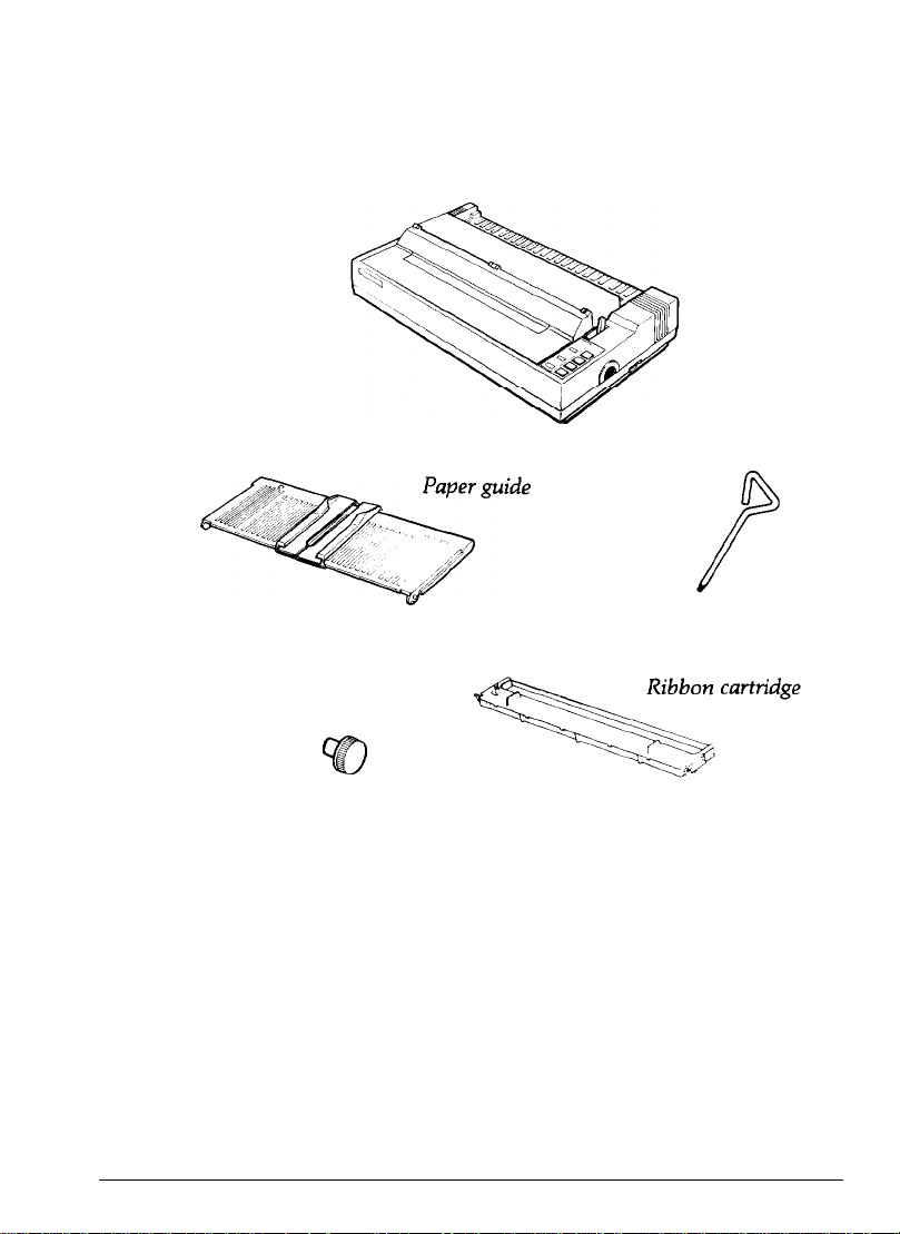
Unpacking the Printer
As you unpack the printer, check that you have all the parts shown
below and
that
none has been damaged during transportation.
Printer
Cross-head screwdriver
Platen knob
Note: You’ll find the platen knob in a piece of the foam packing.
After removing
need to transport your printer.
1-2
the
parts, store
the
packaging materials in case you ever
Setting Up the Printer
Page 11
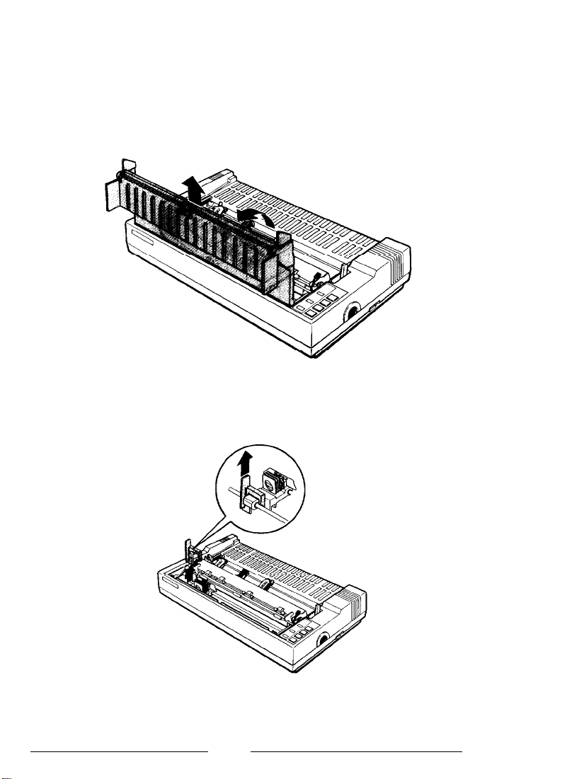
Removing the protective materials
The printer is protected during shipping by two locking tabs and a print
head protector. These protective items must be removed before you turn
on the printer. After removing these items, store them with the other
packaging material.
1
Remove the printer cover.
2.
Remove the print head protector.
Setting Up the Printer
1-3
Page 12
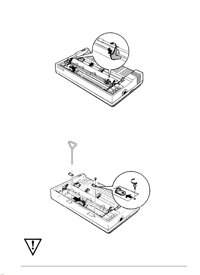
3.
Remove the left and right locking tabs.
4.
Slide the print head to the middle of the printer. Then, use the
enclosed cross-head screwdriver to unscrew and remove the two
transport locking brackets.
1-4
WARNING: Be sure to remove all protective materials before
you turn on the printer.
Setting Up the Printer
Page 13
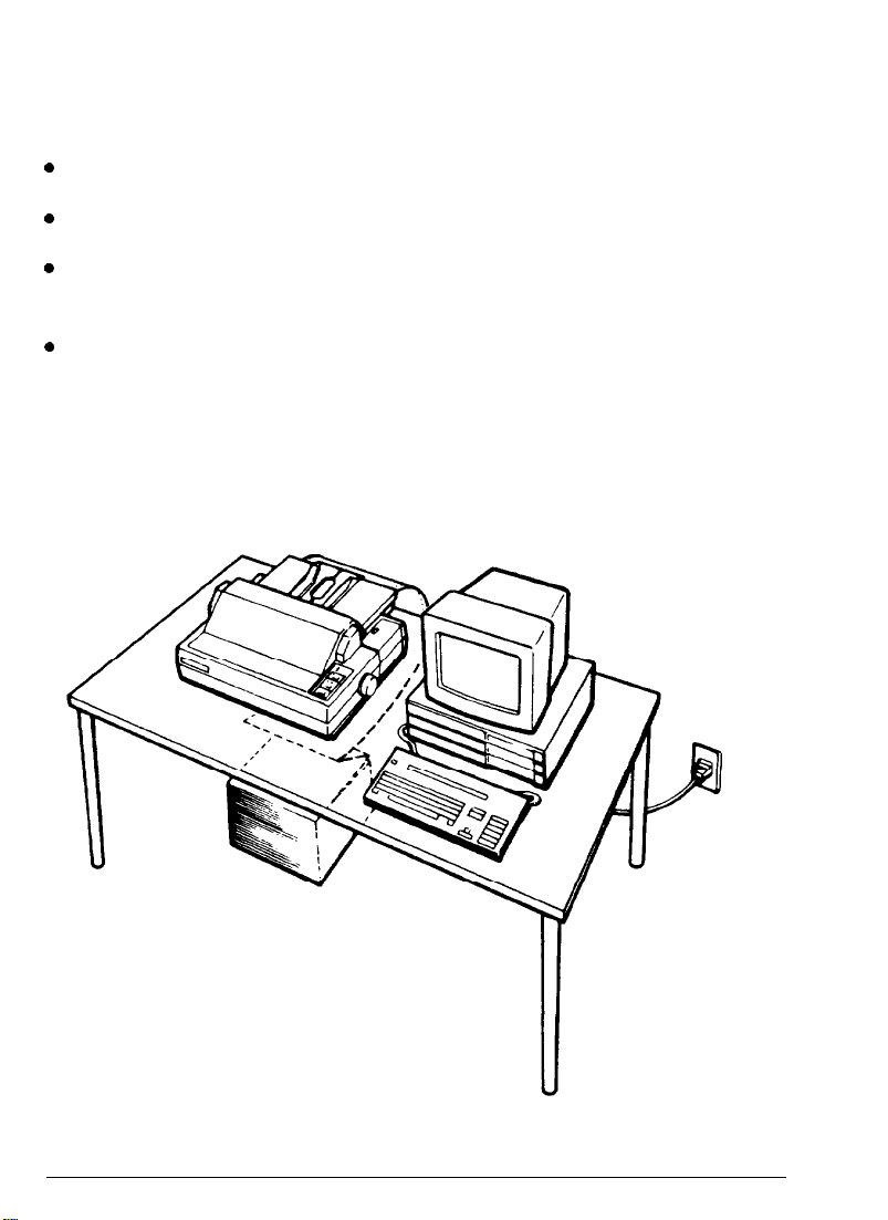
Choosing a Place for the Printer
When you select a location for your printer, keep the following
in mind:
l
Place the printer on a flat, stable surface.
l
Place the printer close enough to the computer for its cable to reach.
l
Leave adequate room around the printer to allow for easy operation
and maintenance.
l
Use a grounded outlet; do not use an adapter plug.
The illustration below shows a good printer setup.
Setting Up the Printer
1-5
Page 14

WARNING:
l
Avoid locations that are subject to direct sunlight,
excessive heat, moisture, or dust.
l
Avoid using electrical outlets that are controlled by wall
switches or automatic timers. Accidental disruption of
power can wipe out information in both your computer’s
memory and your printer’s memory.
l
Avoid using outlets on the same circuit with large motors
or other appliances that might disturb the power supply.
l
Keep the entire computer system away from potential
sources of interference such as loudspeakers or the base
units of cordless telephones.
Assembling the Printer
To assemble the printer, you need only do the following:
l
Install the platen knob
l
Install the ribbon cartridge
l
Attach the paper guide.
Installing the platen knob
The first step in setting up the printer is to install the platen knob. You
should never need to use this knob during the normal operation of your
printer. However, in case of a paper jam, you can use this knob to
manually feed paper. (Be sure the printer is turned off before using the
platen knob.)
You’ll find the platen knob packed in an
indentation in the white foam packing
material.
1-6
Setting Up the Printer
Page 15
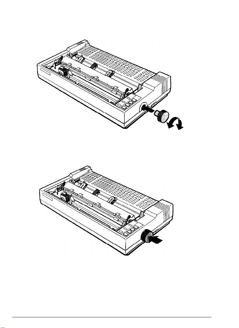
1.
Insert the knob into the hole on the printer’s side and rotate it until it
slips onto
2.
Push firmly on the
the
shaft.
knob
until it fits against the printer
case.
Caution: Never use the platen knob to adjust the position of the paper
except in the case of a paper jam. Only use the platen knob when the
printer is turned off.
Setting Up the Printer
1-7
Page 16
Installing the ribbon cartridge
Follow these steps to install the ribbon cartridge:
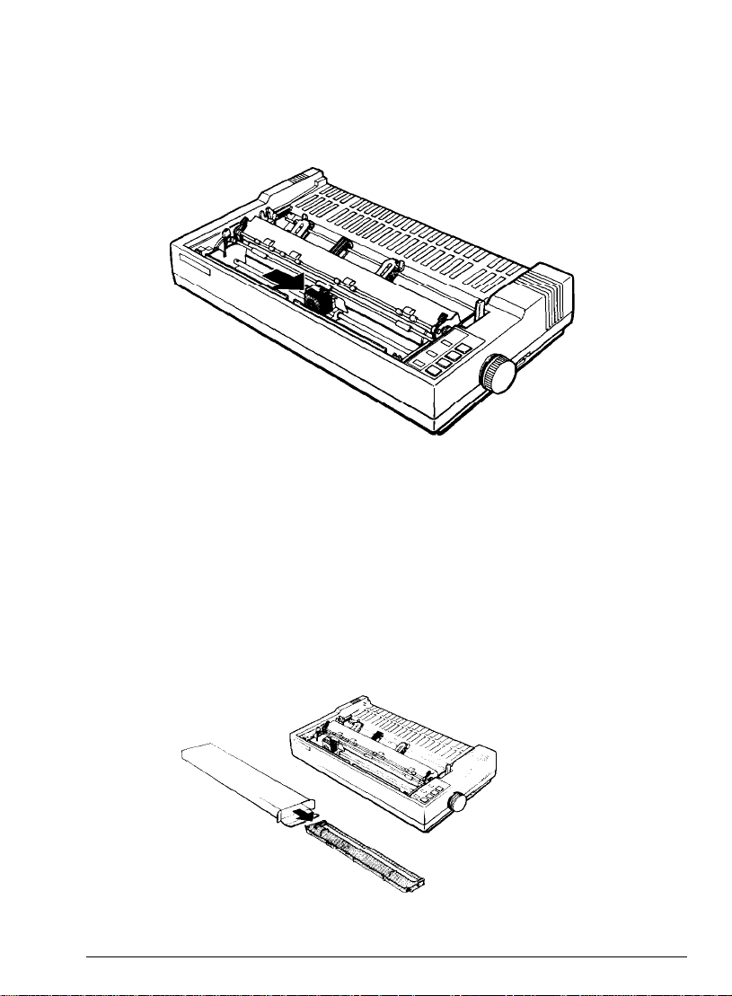
1. Slide the print head to the middle of the printer.
Caution: Never move the print head while the printer is turned on
because this can damage the printer. Also, if you have been using the
printer, the print head may be
hot;
let it cool for a few minutes before
touching it.
2. Remove the ribbon cartridge from its box and remove the plastic
wrapper.
1-8
Setting Up the Printer
Page 17
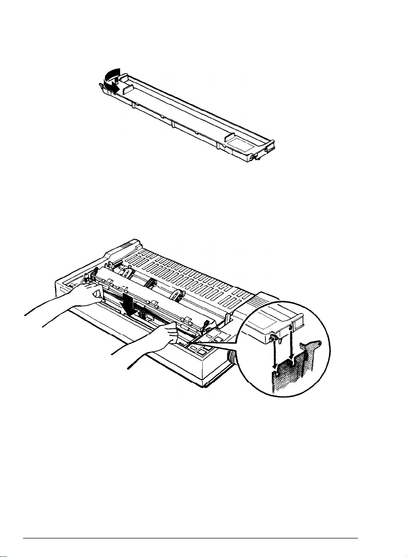
3. Turn the ribbon-tightening knob in the direction of the arrow. This
removes any excess slack in the ribbon and makes it easier to install.
4.
Hold the ribbon cartridge by its handles and push it firmly down
into position, making sure the plastic hooks fit into the printer. (The
FX-850 has only one handle in the center of the ribbon cartridge.)
Press lightly on both sides of the cartridge to be sure the hooks are
properly inserted.
Setting Up the Printer
1-9
Page 18
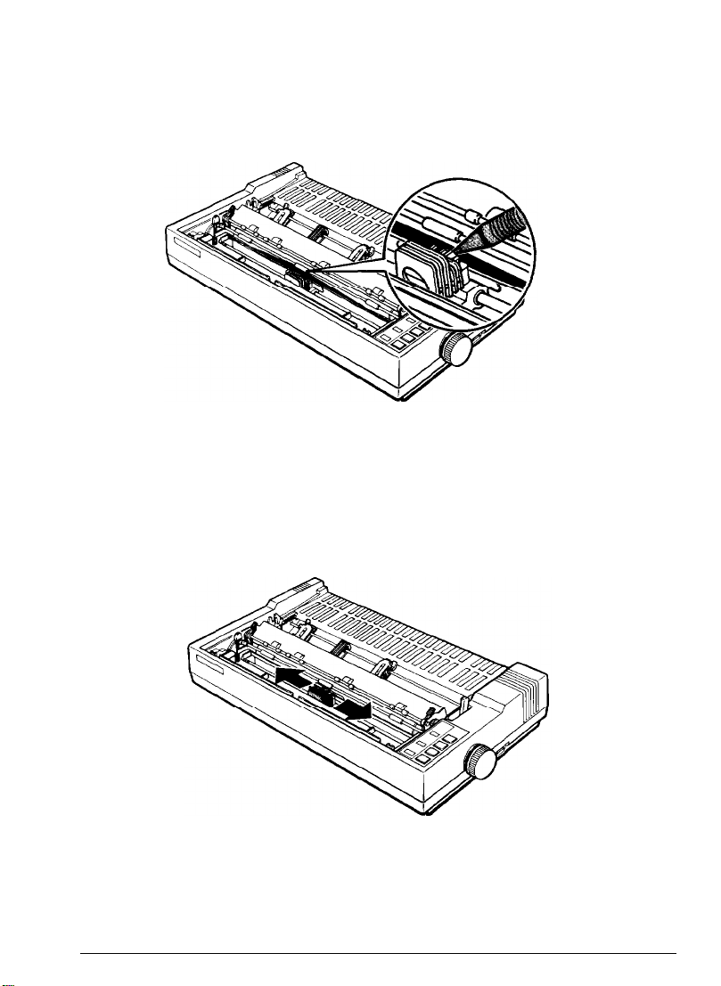
5.
Use a pointed object, such as the tip of a pencil, to guide the ribbon
between the print head and ribbon guide while you turn the ribbontightening knob to help feed the ribbon into place.
6. Slide the print head from side to side to make sure it moves
smoothly. Also make sure the ribbon is not twisted or creased.
1-10 Setting: Up the Printer
Page 19
Attaching the paper guide
The paper guide functions to feed the paper smoothly and efficiently.
Follow these steps to install the paper guide:
1.
Place the paper guide on the printer.
2.
Raise the paper guide until it locks into place.
Setting Up the Printer
1-11
Page 20
3.
Now reinstall the printer cover by fitting the legs of the cover into
the notches at the front of the printer.
4.
Close the printer cover.
Testing the Printer
Now that your printer is fully assembled, you can use the built-in self
test function to see that the printer is working correctly even though it is
not connected to a computer. Be sure to perform this test to check that
your printer is operating properly
Before running the self test, you need to connect your printer to an
electrical outlet and load a sheet of paper.
1-12
Setting Up
the
Printer
Page 21
Plugging in the printer
Follow these steps to plug in the printer:
1. Be sure the printer is turned off.
2.
Plug the power cable into a properly grounded electrical outlet.
WARNING: Whenever you turn off the power, wait at least
five seconds before turning it back on. Rapid switching on
and off can damage the printer.
Loading a sheet of paper
Next, you need to load a sheet of paper
FX-850) or 14 inches wide (if you have an FX-1050).
that
is letter size (if you have an
WARNING: Before turning on the printer, be absolutely sure
you have removed all protective materials. Turning on the
printer while the print head cannot move may seriously
damage the print mechanism.
1.
Turn on the printer. The green
on.
POWER
and red
PAPER OUT
lights come
Setting Up the Printer
1-13
Page 22
be sure that the paper release lever is pushed back to the single sheet
2.
position.
Move the left edge guide so it locks in place
3.
paper guide.
1-14
next to the arrow on the
setting Up the Printer
Page 23
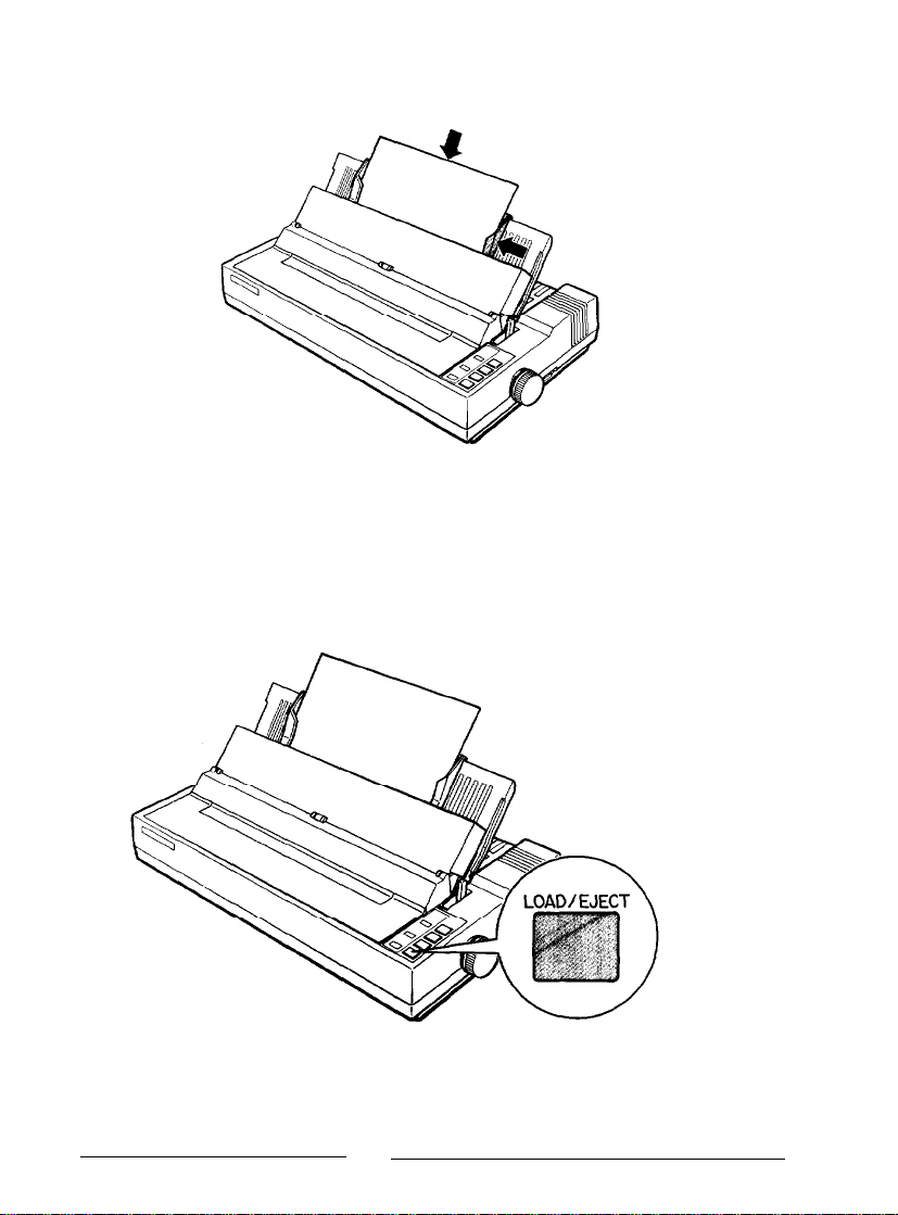
4.
Adjust the right edge guide to match the width of your paper. Next,
slide a sheet down between the edge guides until it meets resistance.
5.
Press the
LOAD/EJECT
button once to automatically load the paper. If
the platen turns without loading the paper, remove the paper
completely and re-insert it more firmly; then press the
LOAD/EJECT
button again.
Setting Up the Printer
1-15
Page 24
Running the self test
The self test can be run in draft mode or near letter quality (NLQ) mode.
Follow the steps below.
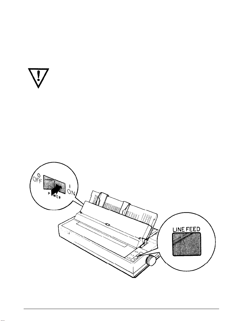
1.
Load a sheet of paper as described above.
WARNING: Never run the self test using paper that is
narrower than 8¼ inches if you have an FX-850, or
if you have an FX-1050, because you may seriously damage
14 inches
the print head.
2.
Turn off the printer.
3.
While holding down the
printing starts, release the
LINE FEED
LINE FEED
button, turn on the printer. After
button.
1-16
Setting Up the
Printer
Page 25
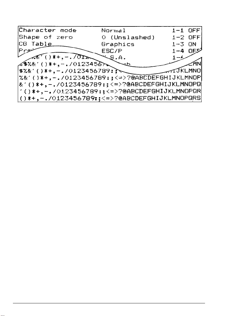
A list of your printer’s settings is printed first, followed by a series of
characters. Here is part of a typical draft self test:
%‘( )*+,-.
’ t I*+,-
t I*+,--.
4.
The self test continues until the paper runs out or until you press the
ON LINE
/t312345(5’7#9:
, ./(.,.j.;:345,5789: a. .
/ (:) J 2 3 4 5 6 7 $3 9 :.; c, -
button. To stop the test temporarily, press the
;
,:::=:.
~?@APCDEI=‘GH I J
..-...
,’ -‘s.?&APCDEF~GH I
‘--“.‘;:@!ABC;DEFGH 1 J
,i
KLMNC)POI
J
KI....MNUF’GlK
&MNU/=QFtS
ON LINE
button to take the printer off line.
5.
To end the self test, be sure
EJECT
button to eject any paper that is still loaded, and then turn off
the
printer is off line. Press the
LOAD/
the printer.
Note: When the cut sheet feeder is installed, the self test printout is
slightly
different. For details, see the section on the cut sheet feeder in
Chapter 7.
To run the self test in NLQ mode, follow these steps:
1.
Load another
2.
Turn off the printer, then turn it on again while holding down the
FORM FEED
sheet
of paper as described above.
button. After printing starts, release the
FORM FEED
button.
Setting Up the Printer
1-17
Page 26
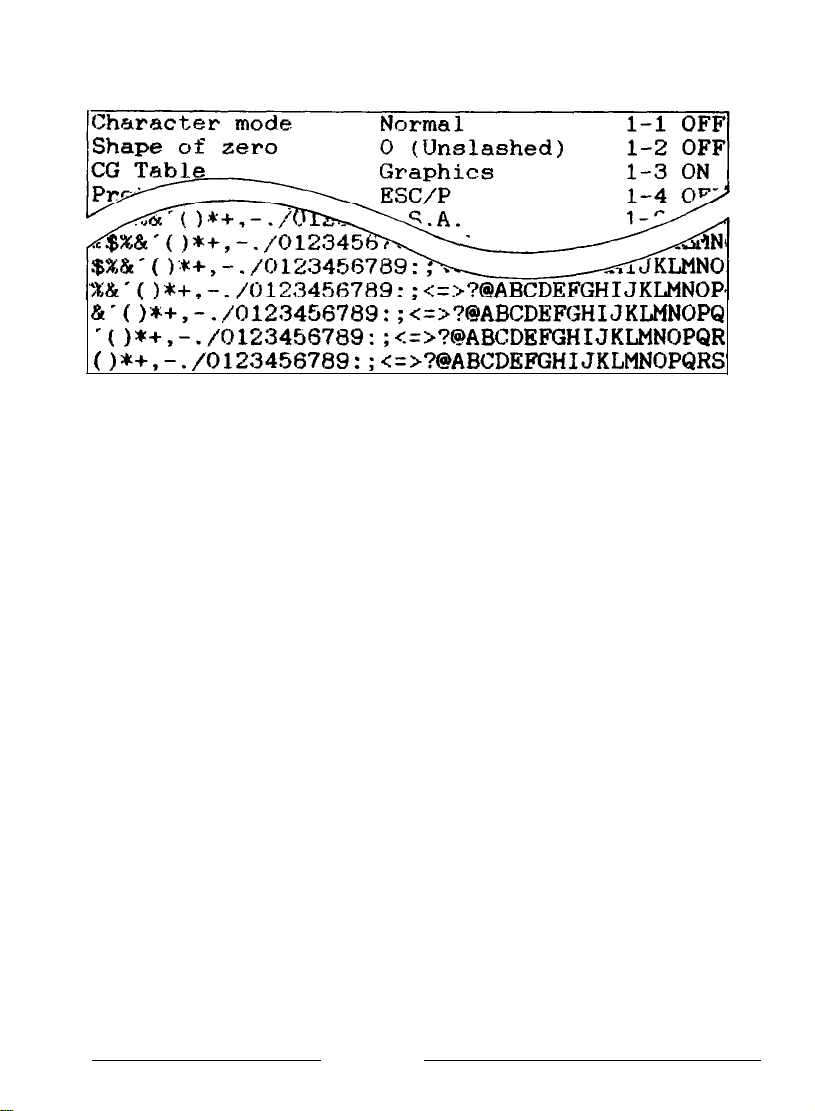
Part of a typical self test in NLQ mode is shown below:
a-()*+,-.
‘(I*+,-./0123456’789:;~=~?t@ABCDEFGHIJKLMNOPQR
(I*+,-./0123456789:;~=~?@ABCDEFGHIJKLMNOPQRS’
3.
To end the self test, press
line. Then press
off the printer.
/0123456789:;<=>?BABCDEFGHIJKLMNOPQ
the ON LINE
the LOAD/EJECT
button to take the printer off
button to eject the paper, and turn
Connecting the Printer to Your Computer
If the self test printed correctly and your printouts looked like the ones
shown, you are now ready to connect your printer to the computer.
Your FX printer has a Centronics®-compatible parallel interface. If you
have a suitable shielded cable, you should be able to connect your
printer immediately. If your computer requires the use of another type of
interface, you need to install an optional interface board.
If you are unsure whether your computer has a parallel interface, see
your computer’s operating manual. If the computer cannot use a parallel
interface, see the section
on
interface boards in Chapter
7.
Connecting the parallel interface cable
Connect
1.
the
parallel interface cable as described below:
Turn off both the printer and your computer.
1-18
Setting Up
the
Printer
Page 27
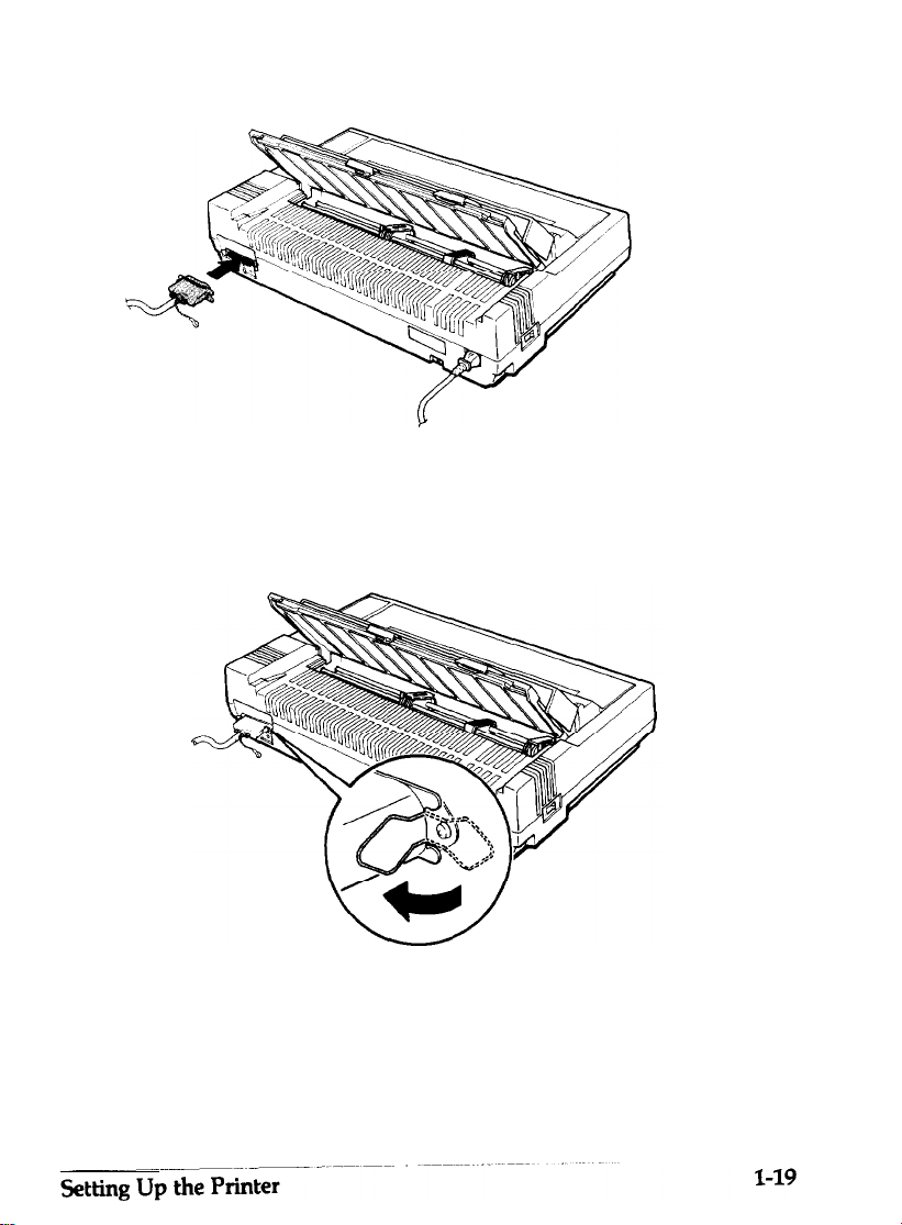
2.
Plug the cable connector securely into the printer.
3.
Squeeze the wire clips together until they lock in place on either side
of the connector.
Note: For your printer to work properly, this connection must be
secure.
Page 28
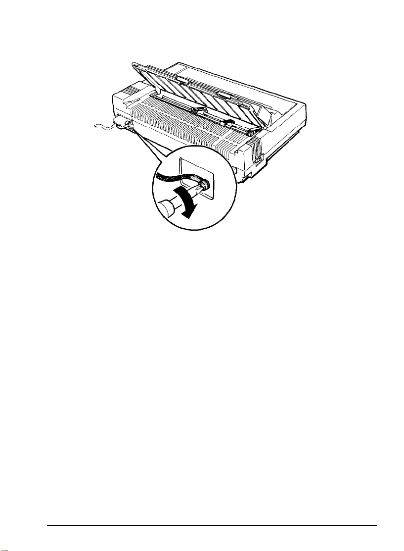
4.
If your cable has a ground wire, connect it to the ground connector
beneath
5.
Plug the other end of the cable into the computer. (If there is a
ground wire at the computer end of the cable,
the
interface connector.
attach
it to the ground
connector at the back of the computer.)
1-20
Setting Up the Printer
Page 29

Chapter 2
Paper Handling
Using Single Sheets
Reloading during printing
Using Continuous Paper
Positioning your continuous paper supply
Switching Between Continuous and Single Sheets
Switching back to continuous paper
Adjusting the Loading Position
Using Micro-Adjustment
Using Short Tear-Off
Printing on Special Paper
The paper thickness lever
Multi-part forms
Labels . . . . . . . . . . . . . .. . . . . . . . . . . . . . . . . . . . . . . . . . . . . . . . . . . . . . . . .
Envelopes
..........................................
.................................
....................................
.....................
...............
.........................
...............................
...................................
.......................................
....................................
.................................
.........................................
..............................................
2-2
2-4
2-4
2-9
2-10
2-13
2-14
2-14
2-15
2-17
2-17
2-18
2-19
2-19
Paper Handling
2-1
Page 30
Using Single Sheets
Your printer can handle a wide range of paper sizes up to a maximum
width of
Always make sure that your printing is confined to the size of paper you
are using. Never print on the platen (black roller).
If you do most of your printing on single sheets, you may find it more
convenient to install the optional cut sheet feeder. This option
automatically inserts a new sheet whenever required and can hold up to
150 pages or 25 envelopes. For more details, see Chapter 7.
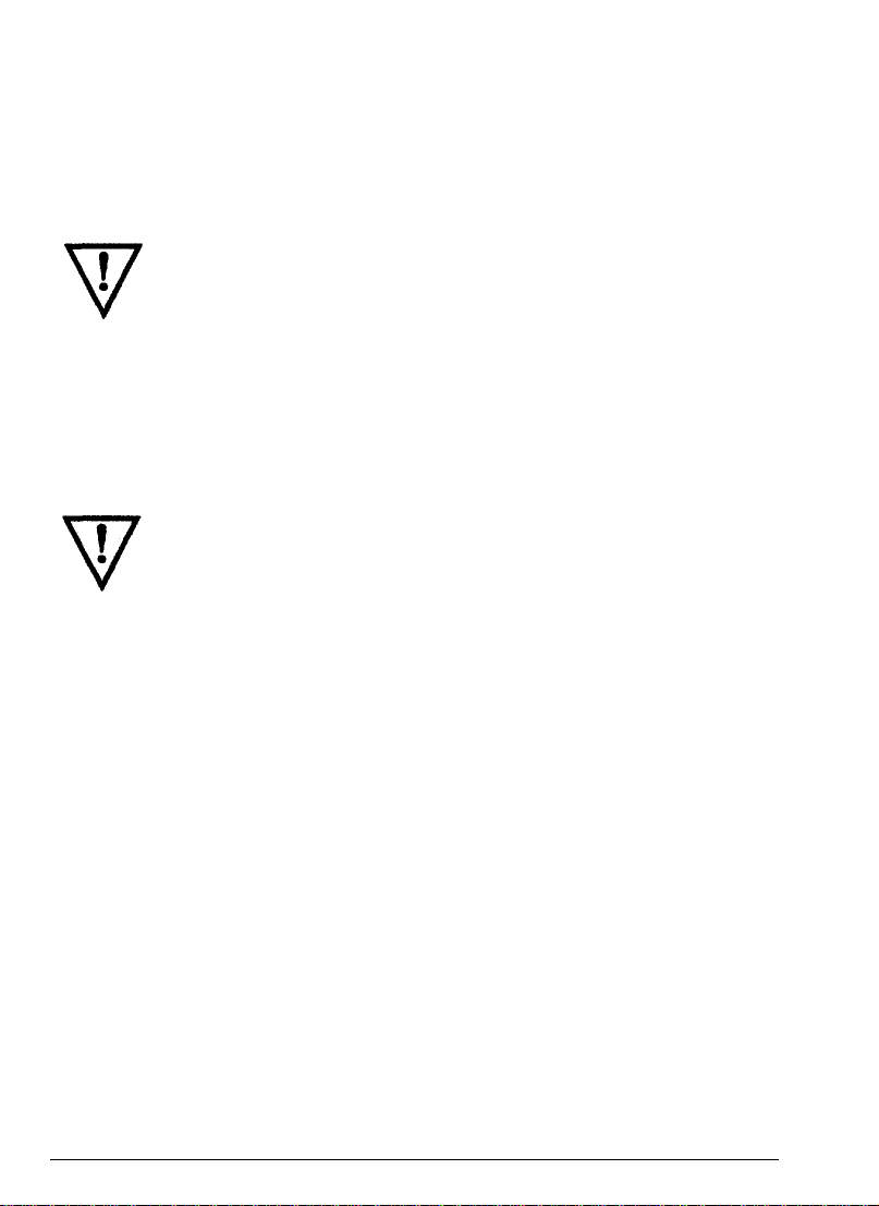
To load a single sheet of paper follow these steps:
10.1
inches on the FX-850 or
14.4
inches on the FX-1050.
Note: If you
instructions on page
single sheets.
Turn on the printer.
1.
Push the paper release lever back to the single sheet position.
2.
already have
continuous
2-10
for switching between continuous
paper loaded, follow the
paper and
2-2
Paper Handling
Page 31

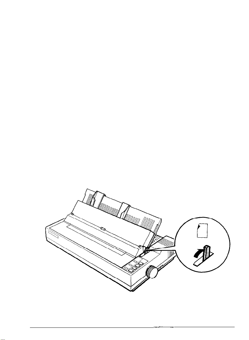
3.
Stand the paper guide in an upright position and align the left edge
guide with the arrow on the paper guide. (You may want to change
this position later, depending
application program.)
on
the margin settings of your
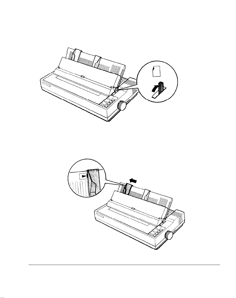
4.
Adjust the
5.
Slide the paper down between the edge guides until it meets
resistance. At this point,
6.
Press the
loading position.
right
edge guide to fit the size of the paper.
the PAPER OUT
LOAD/EJECT
button to automatically feed the paper to the
light turns off.
WARNING: Never advance the paper using the platen knob
while the printer is turned on.
7.
Press the
ON LINE
button so that the
ON LINE
indicator lights up.
Paper Handling
2-3
Page 32

If the platen (black roller) turns but the sheet does not load, remove the
sheet completely from the printer. Then make sure the paper release lever
is pushed back. Press the paper a bit more firmly into place and try
again.
To eject the paper, press the
and press
the LOAD/EJECT
ON LINE
button.
button to take the printer off line,
Reloading during printing
When you print a document more than one page long using single
paper, the printer stops printing when it reaches the bottom of the paper
and ejects the page. When this happens, either the
automatically or it may remain on, depending on your application
software. If the
press the
light is off, remove the sheet that has just been printed and load a new
sheet as before. Press
ON LINE
ON LINE
light remains on, the first thing you should do is
button to take the printer off line. Once the
ON LINE
to start printing the next page.
ON LINE
sheet
light goes off
ON LINE
Using Continuous Paper
The tractor built into the FX is remarkably easy to load and operate. Its
low-profile design takes up little space and can handle a wide variety of
paper widths.
To load continuous paper, follow these steps:
1. Turn off the printer.
2.
Pull the paper release lever forward to the continuous paper position.
2-4
Paper Handling
Page 33

3.
Release the sprocket lock
4.
Slide the left sprocket unit all the way to the left and lock it in place.
levers
by pulling each lever forward.
Paper Handling
2-5
Page 34

5.
Next, slide the right sprocket unit to match roughly the width of
your paper. (Do not lock it.)
6.
Slide the paper support to a point midway between the sprocket
units.
7.
Open both sprocket covers.
2-6
Paper Handling
Page 35

8. Fit the first four
as
shown below. Then close the sprocket covers.
9. Slide the right sprocket unit to a position where the paper is straight
and has no wrinkles, and then lock it in place.
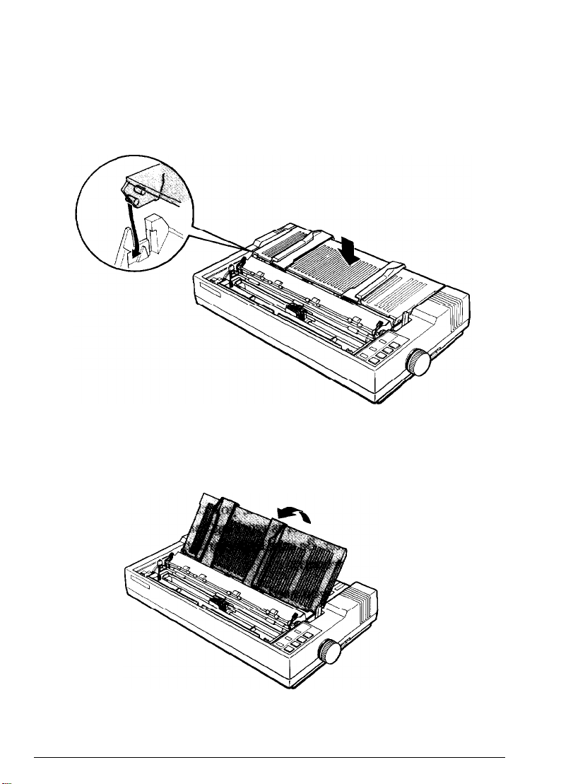
10. Reattach the paper guide as shown below.
holes
in the paper over the pins of the sprocket units
Paper Handling
2-7
Page 36

Caution:
edge guides are pushed together.
11.
Close
12.
Press the
position. The printer remembers this position and advances each
page to the same position.
13.
Press the
accept data.
When using continuous
the
printer cover and turn on
LOAD/EJECT
ON LINE
button to feed the paper to the loading
button to put the printer on line
paper, always make sure that the
the
printer.
so that
it
can
If you find
prints too high or too low on the page or is printing on the perforations,
check the loading position. If you need to adjust this position, you can
use the micro-adjustment feature. This feature gives you precise control
over the position of your paper by allowing you to feed the paper
forward or backward in 2/216-inch increments. For more information,
see the section on micro-adjustment later in this chapter.
When using continuous paper, you can also choose
feature to give you added paper handling capabilities. This feature
automatically feeds the paper forward so that you can tear it off at its
perforation. The printer then reverses the paper feed so you can resume
printing at the loading position. Short tear-off makes it easier to detach
printed pages and saves the blank pages that are usually lost between
printing jobs. See the section on short tear-off later in this chapter for
details.
that
your word processing or other application program
the
short tear-off
WARNING:
If you need to adjust the loading position,
always use the micro-adjustment feature. Never advance the
paper using the platen knob while the printer is turned on.
2-8
Paper Handling
Page 37

Positioning your continuous paper supply
Three common ways of positioning your printer and continuous paper
supply are shown below.
It’s important to keep your paper supply aligned with the tractor
so that
the paper feeds smoothly into the printer.
Paper Handling
2-9
Page 38

Switching Between Continuous and Single Sheets
Even with continuous paper loaded in the printer, you can easily switch
to single sheet printing without removing
tractor. To switch from continuous paper to single
steps below.
1.
Open the printer cover and press
printer off line.
the
continuous
the ON LINE
paper from the
sheets,
button to take the
follow the
2.
Remove your printed document. If you are
off function, press the
to a
point where it
FORM FEED
can be
removed.
button to advance your document
not
using the short tear-
Note: To avoid feeding your continuous paper backward more than is
necessary, always make sure that you tear off the printed document
before removing paper with the
2-10
LOAD/EJECT
button.
Paper Handling
Page 39

3.
Press the
out of the printer and into a standby position. The paper is still
attached to the tractor, but is no longer in the paper path. The
PAPER OUT
paper path.
Note:
back enough to reach a standby position. If the PAPER
LOAD/EJECT
light comes on when the paper is completely out of the
Pressing the
LOAD/EJECT
button to feed the continuous paper backward
button
once may not feed the paper
OUT light
does
not come on, press the LDAD/EJECT button again. With normal
continuous paper, you
times. (With continuous paper narrower than six
the LOAD/EJECT button only once.)
4.
Push the paper release lever back to the single sheet position.
can press the LOAD/EJECT
button up to three
inches, you can
press
Paper Handling
2-11
Page 40

5.
Stand the paper guide upright, and adjust the edge guides to roughly
match the width of your paper.
6.
Close the printer cover. Next, slide the paper between the edge guides
until it meets resistance. At this point, the
PAPER OUT
light turns off.
Press the
7.
loading position.
2-12
LOAD/EJECT
button to automatically feed the page to the
Paper Handling
Page 41

8.
Press the
ON LINE
button to put
the
printer on line.
Switching back to continuous paper
To switch back to printing with continuous paper, first eject the single
sheet of paper and take the printer off line.
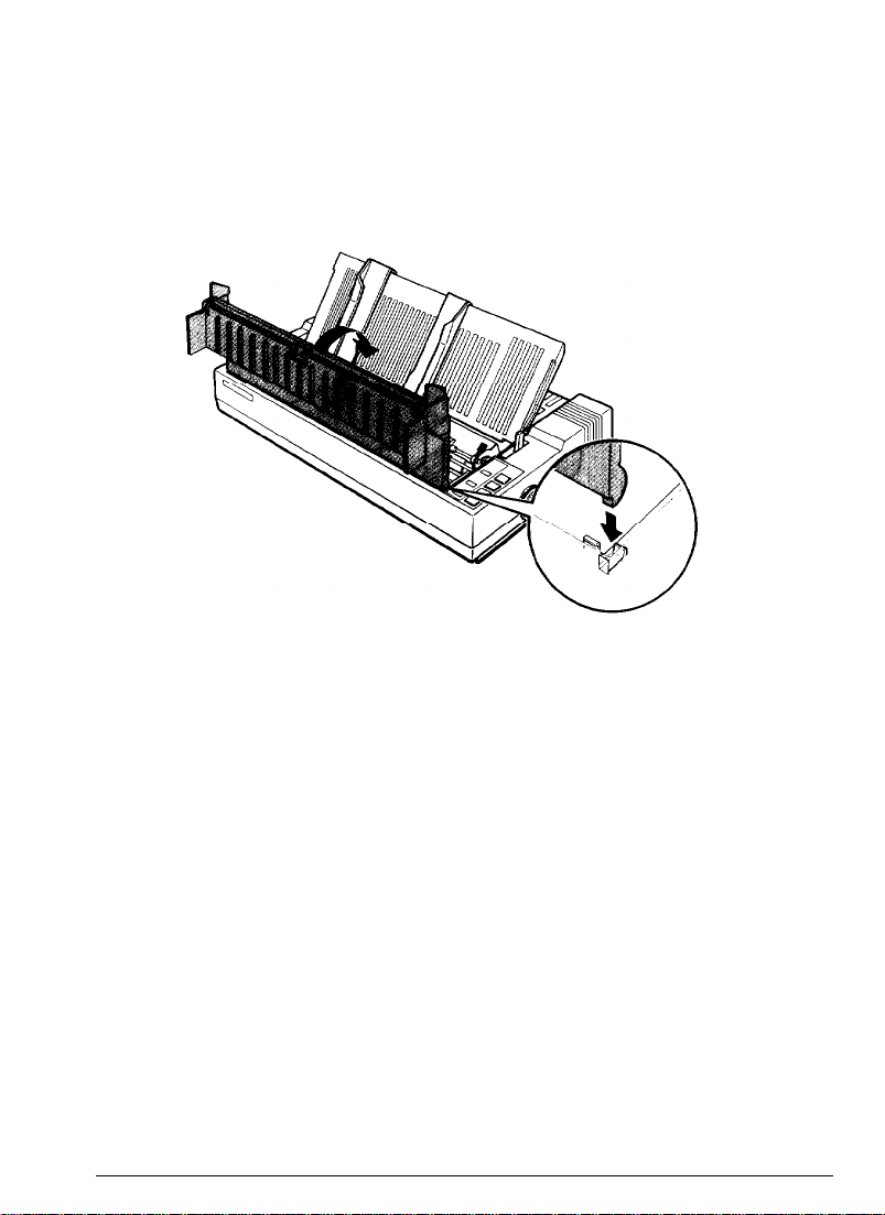
1.
Open the printer cover. Lower the paper guide onto the back of the
printer.
2. Pull the paper release lever forward to
3.
Press the
position.
4.
Press the
LOAD/EJECT
ON LINE
button to put
button to feed
the
the
the
paper to the loading
printer on line.
Paper Handling
continuous paper position.
2-13
Page 42

Adjusting the Loading Position
The loading position is
automatically loaded by
determines where the printing begins on
high or too low on the page, you need to change the loading position
using the micro-adjustment feature described in the next section.
Until the loading position is reset, the printer remembers the position and
uses it as a reference point for feeding the paper.
WARNING: If you need to adjust the loading position,
the
position of the paper when it has been
the
printer. This position is important because it
the
page. If the printing is too
always use the micro-adjustment feature. Never use the
platen knob for paper feeding except in case of a paper
feeding problem.
Once you
continuous paper, the printer remembers
turned off. However, when you use micro-adjustment to change the
loading position of single
position after the power is turned off. When
on, the loading position returns to its factory setting.
have
used micro-adjustment to change the loading position of
that
position even after it is
sheet
paper, the printer does not remember this
the
power is turned back
Using Micro-Adjustment
The micro-adjustment feature moves the paper 2/216th of
time to make fine adjustments to the loading or short tear-off positions.
Micro-adjustment only works immediately after you load paper or use
the short tear-off function. You can use micro-adjustment only when the
printer is on line and
the ON LINE
indicator light is flashing.
an
inch at a
After you adjust the tear-off position or after you adjust the loading
position for continuous paper, the printer remembers
after it is turned off, reset, or initialized. However, when you adjust the
loading position for single-sheet paper, the printer does not remember
new
position after the power is tuned off.
2-14
that
position even
Paper Handling
the
Page 43

This section describes using micro-adjustment to change the loading
position, but you can adjust the short tear-off position the same way. See
the next section on using short tear-off for more information.
To perform micro-adjustment of the loading position, first load your
paper, and then press the
ON LINE
use the
indicator light starts to flash. While this light is flashing, you can
FORM FEED
and
LINE FEED
ON LINE
button to put the printer on line. The
buttons for micro-adjustment.
Press the
button to feed the paper backward.
Each time you press the button, the paper moves
you hold the button down, the paper moves continuously in 2/216-inch
increments.
When the paper reaches the factory-set loading position, the printer
beeps and micro-adjustment feeding pauses for a moment before
continuing. You can use this factory setting as a reference point when
adjusting the printer’s loading position. When the paper reaches either
the
stops moving.
FORM FEED
minimum or maximum top margin, the printer beeps and the paper
button to feed the paper forward or the
2/216
LINE FEED
of an inch. If
Using Short Tear-Off
When you are finished printing, the short tear-off feature automatically
feeds the perforation of the continuous paper to the tear-off edge of the
printer cover
printing, the printer reverses the paper back to the loading position so
that you can use all of the next sheet.
so that
WARNING: Never use short tear-off with labels.
you can tear off the last sheet. When you resume
To use short tear-off, first turn off the printer and turn DIP switch
off. (See the section on setting DIP switches in Chapter 3.) Then load
continuous paper as usual, but leave the rear section of the printer cover
open so that you can use the cover as a tear-off edge.
Paper Handling
1-5
2-15
Page 44

The short tear-off function operates as follows:
1. The perforation at the end of the last printed page feeds to the tear-off
edge of the printer cover.
2. Tear off
the
page using the printer cover’s tear-off edge.
3. If you need to adjust the position of the perforation to meet the tearoff edge, use micro-adjustment. This feature adjusts your tear-off
position only when you use it immediately after short tear-off. First,
make sure that the printer is on line and the
flashing.
by pressing the
LINE FEED
Then,
adjust the position in 2/216th-of-an-inch increments
FORM FEED
button to feed the paper forward or the
button to feed it backward.
ON LINE
indicator light is
After micro-adjustment,
valid
even
after the printer is turned off, reset, or initialized.
the
new tear-off position is reset and remains
4. When you resume printing after tearing off the sheet, the paper
automatically feeds backward to the loading position before printing
begins.
2-16
Paper Handling
Page 45

You can leave the short tear-off feature turned on (DIP switch 1-5 off)
even when you are using single sheets. When you move the paper release
lever to the single sheet position, short tear-off is disabled.
Printing on Special Paper
In addition to using single sheets and continuous paper, your printer can
also print on a wide variety of paper types, including multi-part forms
and labels. You can even feed envelopes, either manually or with the
optional cut sheet feeder. Before printing on these special types of paper,
however, you need to adjust the paper thickness setting.
The paper thickness lever
To accommodate various thicknesses of paper, the FX printer is equipped
with a paper thickness lever that can be set to eight positions. These
positions are identified by a scale on the printer frame next to the lever.
Before changing the paper thickness setting, first make sure the power is
off and then remove the printer cover.
WARNING: If you’ve been using the printer just before
opening the printer cover, be careful not to touch the print
head because it may be hot.
Select the paper thickness you want according to the figure below. For
normal use, the lever should always be set to position 2 on the scale.
Paper Handling
2-17
Page 46

For printing on special types of paper, see the table below. It gives you
general guidelines for selecting the right paper thickness lever position to
match your paper.
Paper Type
Paper (single sheets or continuous)
Thin paper
Multi-part paper
3-sheet
4-sheet
Labels
Envelopes
Air mail
Plain
Bond (20 lb.)
1 Bond (24 lb.)
Always return the lever to position 2 when you go back to printing on
ordinary paper. Continuous printing with the lever set at a position
higher than 2
1
.
can
shorten the life of the print head.
WARNING: Printing past the edge of envelopes, multi-part
forms, labels, or thick paper can damage the print head.
Lever Position
2
2
i
4
3
3 or 4
z
6
77
When you print on anything thicker than normal paper, such as
envelopes or multi-part forms, be absolutely sure that your printing stays
within the printable area of the paper. See page 2-20 and Appendix A for
more about the printable area of the paper.
Multi-part forms
Your printer can also use continuous multi-part forms. These multiple
forms should have no more than four parts including the original.
Note: Multi-part forms should not be used with the single sheet
feeding system or the optional cut sheet feeder.
2-18
Paper Handling
Page 47

You load continuous multi-part paper the same way that you load
continuous paper. See the section on loading continuous paper in this
chapter for details. The only difference is that you need to adjust the
paper thickness lever to suit the thickness of your paper before loading.
See
the
table above for the correct paper thickness setting.
Labels
If you need to print labels, always choose the type mounted on a
continuous base sheet provided with sprocket holes for use with the
tractor. If you attempt to print labels using the single-sheet feeding
system, labels on a shiny base sheet almost always slip a little.
You load labels the same way that you load continuous paper. See
section on loading continuous paper in this chapter for details. The only
difference is that you need to adjust
the
thickness of your labels. See the table above for the correct paper
thickness setting.
To remove labels, tear off at a perforation behind the push tractor. Then
take the printer off line and
use the FORM FEED
WARNING: Never feed the labels
the
paper thickness lever to match
button to eject the labels.
backward through the
the
printer. Labels can easily come off the backing and jam the
printer. Therefore,
never use the LOAD/EJECT
button to eject
labels or to feed labels backward to the standby position.
Also, never use the short tear-off feature with labels. If a
label does become stuck in the printer mechanism, take the
printer to a qualified service person. Since labels are
especially sensitive to temperature and humidity, always use
them under normal operating conditions.
Envelopes
You can print on a variety of envelopes, including air mail, plain, or
bond. To feed envelopes individually, use the single
First, set the paper thickness lever as indicated in
follow the single sheet loading instructions at the beginning of this
chapter.
sheet
loading feature.
the
table above. Then,
Paper Handling
2-19
Page 48

You can also feed envelopes with the optional cut sheet feeder. See the
section on the cut sheet feeder in Chapter 7. Before loading envelopes
into the cut sheet feeder, you need to adjust the paper thickness lever. See
the
table showing envelope types and recommended lever positions on
page 2-18.
WARNING: When
application program settings keep the printing entirely within
the printable area of the envelopes as
printing on envelopes, be sure that your
shown below.
4
10.33
-4
f
0.87” or mom
I 9
0.12” or more
To make sure that
print a test on a single sheet of paper before printing on
envelopes.
the printing fits within this area, always
I
t'
a
or more
2-20
Paper Handling
Page 49

Chapter 3
Using the Printer
Operating the Control Panel
Lights
Buttons
SelecType
Other control panel features
Setting the DIP Switches
DIP switch functions
Selecting Typestyles
Using SelecType
Character fonts
Characters per inch
Condensed mode
If SelecType does not work
Enhancing Your Printing
Character size
Emphasized and double-strike printing
Italic printing
Underlining
Superscripts and subscripts
Selecting typestyles with Master Select
...................................................
.................................................
...............................................
.......................................
.........................................
..........................................
........................................
...........................................
...........................................
..........................................
..................................
...............................
.....................................
......................................
......................................
................................
....................................
.................................
3-2
3-2
3-3
3-4
.3-5
3-5
3-6
3-10
3-11
3-11
3-12
3-12
3-13
3-13
3-13
...................... .3-14
3-15
3-15
3-15
.......................
3-15
Using the Printer
3-1
Page 50

Operating the Control Panel
The buttons on the control panel let you control many of the printer
settings. The control panel also has indicator lights so you can check the
current status of the printer’s various settings.
Lights
POWER
On when the power switch is on and
power is supplied.
READY
On when the printer is ready to
accept input data. Flickers when
receiving data.
PAPER OUT
On when the printer is out of paper
or when continuous paper is in the
standby position.
ON LINE
On when the printer is on line and
ready to accept data. This light
flashes immediately after you load
paper or use short tear-off to indicate
that micro-adjustment can be used.
3-2
Using the Printer
Page 51

Buttons
ON LINE
This button controls the printer’s on
line/off line status. When the printer
is on line, the printer can receive and
print data from the computer.
FORM FEED
When the printer is off line, press this
button to eject a single
or advance continuous paper to the,
top of the next page. When the
printer is on line, you can use the
micro-adjustment feature by pressing
this button to advance the paper.
LINE FEED
When the printer is off line, press this
button to feed the paper one line, or
hold it down to f&d the paper
continuously. When the printer is on
line, you can use the microadjustment feature by pressing this
button to reverse the paper.
sheet
of paper
Using the Printer
LOAD/EJECT
When the printer is off line, press this
button to load paper if paper is not
loaded, or to eject it if paper is
loaded. (Single sheet paper is ejected
forward and continuous paper is
ejected backward.)
3-3
Page 52

SelecType
The
settings
you turn off, reset, or initialize the printer.
you select using the SelecType panel remain valid even after
FONT
Press this button to select draft, near
letter quality Roman, or near letter
quality Sans Serif. The indicator light
shows which font has been selected.
CHARACTERS PER INCH
Press this button to select the
characters per inch (cpi). You can
choose 10 CPI, 12 CPI, or PS
(proportional spacing). The indicator
light shows the selected character
spacing.
CONDENSED
Press this button to select either
condensed or normal printing. The
light is on when the printer is in
condensed mode. In this mode, all
characters are approximately 60% of
their normal width.
Note: Proportional spacing and condensed mode cannot be combined.
If you select both, only proportional spacing works.
3-4
Using the Printer
Page 53

Other control panel features
The control panel of the FX also gives you access to several special
functions.
Self test
Microadjustment
Data dump
By holding down the
while you turn on the printer, you can start the
printer’s self test. This prints out the DIP switch
settings and the characters in the printer’s ROM (Read
Only Memory). See
Chapter 1 for more information.
By pressing the
immediately after loading paper or using short tearoff, you can make fine adjustments to the loading and
short tear-off positions. See the section on microadjustment in Chapter 2 for more information.
By holding down both
buttons while you turn
the
data dump mode. This feature allows advanced
users to diagnose many problems. See the section
the data dump mode in Chapter 6 for more
information.
FORM FEED
the
section on the self test in
FORM FEED
and
the FORM FEED
on
the printer, you can turn on
or
LINE FEED
LINE FEED
buttons
and
LINE FEED
button
on
Setting the DIP Switches
By changing the settings of the two sets of DIP switches behind and
below the platen knob, you
the character set and page length. These new settings become valid
whenever the printer is turned
can
control various printer features, such as
on,
reset, or initialized.
Before you set the DIP switches, turn off the printer. Then use a pointed
instrument, such as the tip of a pen or pencil, to move the switch to
either
the on
turn on the printer.
Using the Printer
or off position. The new settings become valid when you
3-5
Page 54

DIP switch functions
The tables below describe the DIP switch functions. The page numbers
refer you to the page on which each printer feature is described. The
shaded settings are the preset factory settings.
DIP Switch 1
international character set
DIP Switch 2
SW Description
2-1
Page length
2-2
Cut sheet feeder mode
2-3
1 -inch skip over perforation
2-4
Automatic line feed
3-6
See table below
ON
12
On
On
On
inch
OFF
11 inch
Off
Off
Off
Page
3-9
3-10
3-10
3-10
Using the Printer
Page 55

International character sets
Default character set
When DIP switch 1-1 is on, the user-defined character set is the default.
User-defined characters are maintained in printer memory even when the
power is turned off, so the user-defined character set can be selected
simply by setting this switch to on. However, when this switch is on,
new user-defined characters cannot be defined. See Chapter 4 for more
information on user-defined characters. This switch is effective only in
the Epson ESC/P mode.
Zero character
When DIP switch 1-2 is on, the printer prints slashed zeroes (0). When
the DIP switch is off, the printer prints open zeroes (0). This is useful for
clearly distinguishing between uppercase 0 and zero when printing such
items as program lists.
Character table
When DIP switch 1-3 is on, the Epson Extended Graphics character table
is selected.
Extended Graphics character table contains international accented
characters, Greek characters, and character graphics for printing lines,
comers, and shaded areas. If you have an IBM® computer or an IBM
compatible, select the Epson Extended Graphics table when you wish to
print the character graphics as they are displayed on the screen. Since the
character table setting affects only half of the character table, you can
Using the Printer
When
it is off, the italics character table is selected. The Epson
3-7
Page 56

still print text if you
can still print italics if you use the proper software command. If your
printer is in IBM emulation mode (DIP switch
characters are available no matter which character table you select.
The printouts below show which characters are printed in each table.
Italics
'"#g%~'(()t+,-./012345~789:;(=>?@C)BCIUEFGH
IJKLMNOPQffSTUVWXYZC\Il'abcdefghijklmnopq
qrstuvwxyz(;)
Epson Extended Graphics
have
selected the Extended Graphics set. Also, you
1-4
on),
the graphics
Note: You may need to use the ESC 6 command to print some of the
Extended Graphics characters. See Appendix
B.
Printer mode
When
mode. When it is off, the printer operates in
the
return. When switch 1-3 is off, a carriage return is added to each line
feed. The functions of DIP switches
when using the printer in the IBM emulation mode. For details, see the
section on international character sets on
DIP switch
IBM emulation mode, DIP
1-4
is on, the printer operates in the IBM emulation
switch
the
1-3
controls the automatic carriage
1-6, 1-7,
the next
Epson ESC/P mode. In
and
1-8
are also different
page.
Short tear-off mode
When DIP switch
advances the paper so you can tear off the paper, and then reverses the
paper so you can use all of the next sheet. See the section on using short
tear-off in Chapter 2.
3-8
1-5
is off, the short tear-off mode is on. This feature
Using the Printer
Page 57

International character set
Selecting an international character set provides you with the characters
used in other languages. To obtain the desired international character set,
set switches
3-7. The following table shows the characters that differ in each
international character set.
International character sets
0
USA
1 France
2 Germany
3
UK
4 Denmark I
5
Sweden
6
Italy
7 Spain I
8 Japan
9
Norway
10 Denmark II
11 Spain II
12 Latin America
1-6, 1-7,
and 1-8 according to the DIP switch table on page
35 36 64 91 92 93 94 96 123 124 125 126
#s@c\l-‘cI~-
# $ h o c § ^ - i!
#$~Auu...g6iiB
r;$@c\l-‘cII-
#$@fiOA-‘a?0A#nBXuAufski6ati
#$@-\e-clab~i
It $ @ i fi i
#$@[Yl-“iI-
#neiE0Auc5a?a~ii
#$l2fE0AU~908t.i
#$5
#$AiR~itiii66
iRii:‘ifiiti
* * ~ ii 3
III e!
.
-
The countries numbered 8 through 12 are available only through the
ESC R software command. See the Command Summary in Chapter 8.
Also, in IBM emulation mode (DIP switch 1-4 on), a character set
containing international characters (CG character table 2) is selected
whenever any one of DIP switches
1-6, 1-7,
or 1-8 is set to off. If all three
switches are on, CG character table 1 is selected. See Appendix B.
Page length
When DIP switch 2-1 is on, the page length is set to 12 inches. When
it is off, the page length is 11 inches. Other page lengths can be set with
the ESC C and ESC CO commands. See the Command Summary in
Chapter 8.
Using the Printer
3-9
Page 58

Cut sheet feeder mode
When DIP switch 2-2 is on, you can use your printer’s optional cut sheet
feeder. See Chapter 7 for more information on using a cut sheet feeder
with your printer.
Skip over perforation
When DIP switch
last line printed on one page and the first line printed on the next page.
When using continuous paper, this feature causes
printing, skip over the perforation, and then resume printing. If you
adjust your loading position correctly, you can get half of the margin at
the bottom of one page and half at the top of the next page. See the
section on adjusting the loading position later in this chapter.
2-3
is on, a one-inch margin is provided between the
the
printer to stop
Note: Most application programs take care of the top and bottom
margins. Only use skip over perforation if your program does not
provide these margins.
Automatic line feed
When DIP switch
automatic line feed. When it is off, line feeds occur only when the printer
receives line feed codes (LF). Since some computers and application
programs automatically add line feeds to carriage returns, the setting you
use depends on your computer and application program.
2-4
is on, a carriage return code (CR) causes an
Selecting Typestyles
Your printer can produce a wide range of typestyles by combining
different character fonts, pitches, widths, and other enhancements. These
features can be selected by using the SelecType feature on your control
panel or by using software commands. This section describes only the
features controlled by SelecType. To use software commands, see the
section on computer-printer communication in Chapter 4 and the
Command Summary in Chapter
3-10
8.
Using the Printer
Page 59

Using SelecType
You can use the SelecType control panel to choose fonts, pitches, and
condensed printing. The settings you select using the SelecType panel
remain valid even after the printer is turned off, reset, or initialized.
However, commands from your software application program
temporarily override the SelecType settings.
Character fonts
The FX-850 and FX-1050
have
three built-in character fonts:
ROMAN
!“##$%&-( )*+,-
LMNCPQRSTUWXYZ[\]^-‘
WxYZC
t 1"
./0123456789:;<=>?6’ABCDEFGHIJK
abcdefghijklmnopqrstuv
We've just seen your excellent ad for
miniature zebras in a recent back issue of
Trader's Times. What is the price of these
items for quantities of more than one gross?
SANS SERIF
‘“##9X&*()*+,-./0123456789:;<=>?@fiE?CDEFGHIJK
LMNoP~R~T~~WXY~C\~~_~
wxyzc:l”
We’ve just seen your excellent ad for
miniature zebras in a recent back issue of
Trader’s Times.
What is the price of these
abcdefghijklmnopqrstuv
items for quantities of more than one gross?
Using the Printer
3-11
Page 60

The draft mode uses fewer dots per character for high-speed printing.
This makes draft ideal for rough drafts and editing work.
Roman and Sans Serif are near letter quality (NLQ) fonts. Near letter
quality takes a little longer to print but produces nicely formed
characters suitable for most documentation requirements.
Characters per inch
For each of the three built-in fonts, you can choose a character size of 10
or 12 characters per inch (cpi), or proportional spacing.
The following printout compares the different types of spacing.
This is Roman printing in 10 cpi.
This is Roman printing in 12 cpi.
This is Roman printing in proportional.
In the 10 and
space. However, in the proportional mode, spacing varies from character
to character. Therefore, a narrow letter like the lowercase i receives less
space than a wide letter like the uppercase W.
12
cpi modes, each character is given the same amount of
Condensed mode
In
addition to the two pitches and proportional spacing, you can use
condensed mode to change the character size. In the condensed mode,
characters are approximately 60% of the width of normal characters.
Condensed printing is very useful for spreadsheets and other applications
where you need to print the maximum amount of information on a page.
Both 10 and
The printout below compares normal
This is
This is condensed 10 cpi Roman printing.
3-12
12
cpi
can
be condensed, but proportional spacing
10
cpi with condensed
10 cpi Roman printing.
10
Using the Printer
the
cannot.
cpi.
Page 61

Note: Proportional spacing and condensed mode cannot be combined.
If you select both, only proportional spacing works.
If SelecType does not work
Some application programs are designed to control all typestyle
functions. These programs cancel all previous typestyle settings by
sending certain software commands before printing. Because these
commands cancel SelecType settings, you should use the program’s print
options function instead of SelecType to select your typestyles.
Therefore, if SelecType does not work with a particular application
program, consult the software manual for information on selecting
typestyles. Also, see the section on using the FX with application
software in Chapter 4.
Enhancing Your Printing
SelecType controls the printing style of a whole document. Software
commands, on the other hand, can change anything from a single
character to the entire document. By using software commands, you can
obtain many different printing effects with the FX printer, from arranging
the text on the page to giving extra emphasis to particular words and
phrases. This section shows you the features you may want to select with
your software. Once you have read about the features, you can find
their commands in the Command Summary in Chapter 8. Also, see the
section on computer-printer communication in Chapter 4 for more
information on sending commands to the printer.
Character size
Besides 10 and 12 cpi, condensed printing, and proportional spacing,
software commands also offer two other options: double-wide and
double-high printing.
Using
the Printer
3-13
Page 62

The double-wide mode doubles the width of any size characters. This
mode is useful for such purposes as emphasizing headings in reports and
making displays, but is usually not suitable for large amounts of text.
This is double-wide-
Another mode for headings and other special uses is double-high:
This is double-high.
Because of its height, you must leave a blank line above a line of double-
high printing. Otherwise, the double-high letters will overlap the letters
on the previous line.
Double-wide and double-high can be combined to obtain even more
impressive printing results:
Double-high double-wide
Widening or narrowing the characters also widens or narrows the spaces
between words and letters. Because word processors usually create a left
margin by printing spaces, you may need to change the number of
characters on a line to keep the margins correct if you change widths.
For example, a left margin of
space margin using double-wide characters.
10
characters at
10
cpi is the same as a five-
Emphasized and double-strike printing
Emphasized and double-strike printing give your documents added
emphasis. In emphasized mode, the FX prints each character twice as the
print head moves across the paper, with the second printed slightly to the
right of the first. This process produces darker, more fully formed
characters.
3-14
Using the Printer
Page 63

In double-strike mode, the printer prints each character twice, the second
time slightly below the first, making the text bolder. For even greater
boldness, you can combine emphasized and double-strike. (Double-strike
cannot be combined with NLQ mode, however.)
Italic printing
You can use italic characters for special emphasis or as an alternative
typeface. ESC 4 turns on the italic mode even if the current DIP switch
setting is set to the Epson Extended Graphics character table.
This sentence is in italics.
Underlining
The underline mode automatically underlines any piece of text. It
underlines spaces, subscripts, and superscripts. (The printer does not,
however, underline horizontal tabs.)
Superscripts and subscripts
Superscripts and subscripts can be used for printing footnote numbers
and mathematical formulas. The example below combines underlining,
superscripts, and subscripts in a mathematical formula.
average = (a1+................+ an)
n
Selecting typestyles with Master Select
Your printer has a special command called Master Select that allows you
to choose many possible combinations of nine different modes. To send
Master Select codes to the printer, you must first choose the mode
combination you want. The modes you can choose from are
cpi, proportional, condensed, emphasized, double-strike, double-wide,
italics, and underline.
Using the Printer
10
cpi,
12
3-15
Page 64

The format of the Master Select code is shown below:
ASCII:
Decimal:
ESC 1 n
27 33 n
Hexadecimal: 1B 21 n
To send the Master Select codes to your printer in a decimal format, for
example, you send the codes 27, 33, and then whatever value you choose
for the variable n.
The variable n is a number that identifies the typestyle or combination of
typestyles. To find the value of n, look at the Master Select table below
and add up either the decimal or hexadecimal numbers for the features
you want.
Master Select Table
For example, if you want to print a title using double-wide 12 cpi
characters in double-strike mode, you would add these three decimal
numbers together to calculate the value of
12 cpi
Double-strike
Double-wide
1
16
32
n:
n = 49
3-16
Using the Printer
Page 65

After calculating the value of n, you use the Master Select command to
send the value to the printer. To send the Master Select command for
double-wide, 12 cpi, and double-strike, you would use the decimal codes
27, 33, and 49.
ASCII:
Decimal:
ESC ! 1
27 33 49
Hexadecimal: 1B 21 31
Consider these things when you use the Master Select command:
l
Master Select cancels any of the listed features that you do not set.
For example, if you have already set 12 cpi, and you try to use
Master Select to set emphasized double-strike only, the character
width is reset to
l
Proportional overrides 10 cpi, 12 cpi, and condensed.
l
Double-strike cannot be combined with NLQ mode.
10
cpi.
Print quality and font are not part of Master Select and must be set
separately, using either SelecType or the ESC x and ESC k commands.
The method you use to send the Master Select codes to the printer is
determined by your application software. For more information on
sending commands to your printer, see the Computer-Printer
Communications section in Chapter 4 and the Command Summary
in Chapter 8.
Using the Printer
3-17
Page 66

Chapter 4
Using Software and Graphics
Using the FX with Application Programs
Using printer selection menus
A quick test . . . . . . . . . . . . . . . . . . . . . . . . . . . . . . . . . . . . . . . . . . . . . .
Using word processors
Using spreadsheets
Using graphics software
Computer-Printer Communication
Escape sequences
Printer commands
Using the Command Summary
Sending printer commands from within
your software program
Dot Graphics
The print head
Pinlabels..
Graphics commands
Graphics programming
User-Defined Characters
Defining your own characters
..............................................
..........................................
...........................................
.....................................
.......................................
.........................................
........................................
......................................
....................................
...............................
................................... 4-5
.............................
..................................
...................................
..............................
........................
.............................
4-2
4-2
4- 3
4-3
4-3
4-5
4-6
4-6
.4-7
4-7
4-8
.4-9
..4-10
4-11
4-12
4-19
4-20
Using Software and Graphics
4-1
Page 67

Using the FX with Application Programs
Now that you’ve set up and tested the printer, you need to start using it
with your application programs.
Most application programs let you specify the type of printer you’re
using so that the program can take full advantage of the printer’s
features. Many programs provide an installation or setup procedure that
presents a list of printers to choose from. If your application program
has a printer selection menu, use the instructions below.
Using printer selection menus
If your software has a printer selection menu, simply choose FX-850 or
FX-1050. If the menu does not list either of these printers, choose one of
the following. They are listed in order of preference.
FX-850
FX-86e
EX-800
FX-85
FX-80 +
FX-80
FX
LX
MX
Epson printer
Draft printer
If you plan to use the IBM emulation mode, choose IBM Proprinter (if
you have an FX-850), IBM Proprinter XL (if you have an FX-1050), IBM
Graphics printer, or IBM printer, in that order of preference.
Fx-1050
FX-286e
EX-1000
FX-286
FX-185
FX-100 +
FX-100
FX
LX
MX
Epson printer
Draft printer
Note: If your application program does not list the FX-850 or FX-1050,
you may want to contact the
software
manufacturer to see if an
update is available.
4-2
Using Software and Graphics
Page 68

A quick test
After setting up your application program, print a sample document to
make sure
document doesn’t print correctly, recheck the program’s printer selection
and installation procedure. If you’re still having trouble printing, consult
the troubleshooting section in Chapter 6.
the
program and the FX are communicating properly. If the
Using word processors
Word processors usually let you use a fixed set of printer features by
placing markers around the text to be altered. When the document is
printed, the markers are recognized and translated into suitable
commands for your printer. On your screen
markers; others display the text as it will appear-for example, in bold
or italics. This method is normally restricted to features that can be
found on almost all printers, such as bold and underlining.
Some word processing programs also let you insert printer commands in
your text. These commands may or may not be visible on your screen.
This method has
command, not just a limited set. To make use of it, however, you need to
understand how to use your printer’s commands. Check the manual for
your word processor to see if you can place printer commands in your
text, and then see the section in this chapter on computer-printer
communications.
the
advantage of allowing you to use any printer
some
programs show the
Using spreadsheets
Although spreadsheets seldom use as many printing styles as word
processors, they do have some very specific requirements.
If your spreadsheet program provides a list of printers, use the list on
page 4-2 to find the proper selection. If your spreadsheet doesn’t
printer setup routine, read the program’s manual carefully for
information on printing.
A major concern for printing spreadsheets is the width of the printer. The
FX-850 is
You can, however, increase the number of characters on a line by
selecting 12 cpi, condensed mode, or both from the SelecType control
Using
an
80-column printer, and the FX-1050 is a 136-column printer.
Software and Graphics
have a
4-3
Page 69

panel. The table below shows you many characters you can fit on a line
using these options. If your spreadsheet asks the number of columns
your printer can print, decide which mode you will use and supply the
appropriate number from this table.
Unlike word processors, spreadsheet programs usually don’t let you
change printer commands within a spreadsheet. Instead, one style or
mode of printing is used for the whole spreadsheet. With the FX, there
are two main ways of sending commands to control the printing of a
spreadsheet. The first method is to choose condensed from the SelecType
control panel.
For the second method, look in the manual for your spreadsheet to find
out how to send printer commands. Then look in the Command
Summary in Chapter 8 to find the proper codes to send.
For example, your spreadsheet might use a “setup string” to send printer
commands. To prepare a setup string for 12 cpi condensed, you would
look up the proper command in the Command Summary. The command
for
12
cpi is ESC M, and the command for condensed is SI. Because most
spreadsheets use the decimal equivalent for the commands, (also given in
the Command Summary), a setup string for 12 cpi condensed might look
like this:
The number
(condensed).
027
4-4
/027/077/015
is for the escape code,
077
is for M, and
015
is for SI
Using Software and Graphics
Page 70

Using graphics software
The FX is capable of producing finely detailed graphic images. Although
the section on graphics later in this chapter gives specific information on
the graphics commands, the easiest way to take advantage of the FX’s
capabilities is with one of the many graphics programs available.
When buying graphics software, always make sure the program has an
option to print on an FX printer. Any program with an option for an FX
printer should give excellent results, using different dot densities to
produce a realistic scale of grays.
Most graphics programs have a printer selection procedure, in which
case you should check the lists on page
4-2
to find the proper selection.
Computer-Printer Communication
Your computer communicates with your printer using a standardized set
of numbered codes called ASCII codes (American Standard Code for
Information Interchange). When you press the letter A on the keyboard,
it is translated into the ASCII code for A, transmitted to a peripheral
device such as your computer screen or your printer, and then converted
back into the letter A.
There are ASCII codes for all the letters in the alphabet, both uppercase
and lowercase letters, and for the numbers 0 through 9. The ASCII set of
codes also includes most punctuation marks and some codes that control
printer functions.
In the Command Summary in Chapter 8, each code is expressed three
different ways: as an ASCII character, as a decimal number, and as a
hexadecimal (base
represented as the ASCII character A, the decimal number 65, and the
hexadecimal number 41. The numbering system you use depends on
your software and your preferences.
All letters, numbers, and punctuation marks are assigned decimal
numbers from
than
32
are called control codes, because they control the operation of
Using Software and Graphics
32
16)
number. For example, the uppercase letter A is
through
255.
ASCII codes with decimal values of less
4-5
Page 71

your printer and other peripherals. These ASCII characters do not
usually have corresponding keys on the keyboard and cannot be printed
as characters by your printer.
Escape sequences
Although there are more than 30 control codes available to control the
operation of your printer, many more codes are required to run today’s
sophisticated printers. Therefore, ASCII codes are grouped in sequences
to represent certain functions. These code sequences use the ASCII codes
with decimal values of 32 through 255, normally reserved for characters
and punctuation, to control printer functions. This is done by first
sending a standard code to tell the printer that the codes that follow are
to be used as control codes, not as characters or punctuation.
The standard code that is sent at the beginning of one of these code
sequences is the Escape code, decimal value 27. Any sequence of codes
starting with the Escape code is called an Escape sequence. You will
probably see Escape written in different ways-such as ESC, ESC, and
ESCape-in various manuals. In this manual it is in the form of ESC
when used within a command.
Printer commands
In order for the printer to recognize the instructions it receives, ASCII
codes must be sent in a specific format, called a command. An Escape
sequence is a command, as is any ASCII code or sequence of codes that
instructs the printer to carry out a particular function. Your software
continually sends commands to your printer and your computer screen.
These commands instruct the printer to perform such actions as print in
a particular typeface, feed the paper a certain amount after printing each
line, and start printing on a particular spot on the page.
Some software programs let you send these commands yourself. This is a
powerful feature because it allows you to enhance your text in ways that
may not normally be available through the software. For example, many
word processing programs do not offer italics. By inserting a command
in your document, however, you can use italics anywhere you like. The
4-6
Using Software and Graphics
Page 72

commands that your printer recognizes are listed in the Command
Summary in Chapter 8 and on the Quick Reference card at the back of
this manual.
Using the Command Summary
The commands listed in the Command Summary in Chapter 8 consist of
various combinations of ASCII codes. You can use either the ASCII
characters or their decimal or hexadecimal equivalents. For example, the
command to turn on subscript is ESC S1 in ASCII characters. The
decimal format for this command is 27 83 01, and the hexadecimal
format is 1B 53 01.
In the Command Summary, commands are grouped by the printer
functions they control, such as character pitch, print enhancement, and
graphics. You can also look up commands in the list of software
commands in numerical order at the beginning of the Command
Summary. This list gives you page number references for the commands.
Some commands include a variable, such as the letter
the command for selecting
or
cancelling double-high mode is ESC w
When n = 1, double-high mode is turned on, and when
turned off. In the Command Summary, variables are printed in italics to
distinguish them from ASCII characters.
n.
For example,
n = 0,
n.
it is
Sending printer commands from within your software program
How you format commands depends on the software program you are
using. Some software programs accept only the decimal format, while
others require certain punctuation. Some programs don’t let you insert
printer commands at all.
If your software does allow you to send commands to the printer, use the
Command Summary to find the command you want to send. Your
software manual should explain exactly what format and punctuation
are required.
Using
Software and Graphics
4-7
Page 73

Dot Graphics
The dot graphics mode allows your FX printer to produce pictures,
graphs, charts, or almost any other pictorial material you can devise.
Because many commercial software programs use graphics, you may be
able to print pictures and graphs like the ones on this and the following
page simply by giving your software a few instructions.
4-8
Using Software and Graphics
Page 74

The quickest and easiest way to print graphics on your printer is to use a
commercial graphics program. With such programs you usually create
an image on your monitor and then give a command to send the image
to the printer.
If you use commercial software that produces graphics, all you need to
know about dot graphics is how to use the software. If, on the other
hand, you wish to do your own programming or merely wish to
understand how the FX prints graphics, read on.
The print head
To understand dot graphics you need to know a little about how the FX’s
print head works.
The print head has nine pins. As the print head moves across the page,
electrical impulses cause the pins to fire. Each time a pin fires, it strikes
the inked ribbon and presses it against the paper to produce a small dot.
As the head moves across the paper, the pins fire time after time in
different patterns to produce letters, numbers, or symbols.
Using Software and Graphics
4-9
Page 75

The print head is able to print graphics in addition to text because
graphic images are formed on the FX about the same way that pictures in
newspapers and magazines are printed. If you look closely at a
newspaper photograph, you can see that it is made up of many small
dots. The FX also forms its images with patterns of dots. The images
printed by the FX can be as finely detailed as the ones at the beginning of
this section.
In its main graphics mode the FX prints one column of dots for each code
it receives, and it uses only the top eight of the nine pins. Therefore,
your graphics program must send codes for dot patterns, one number for
each column in a line. For each of those columns the print head prints
the pattern of dots you have specified.
To print figures taller than eight dots, the print head makes more than
one pass. The printer prints one line, then advances the paper and prints
another, just as it does with text.
To keep the print head from leaving gaps between the graphics lines as it
does between the text lines, the line spacing must be changed to eliminate
the space between lines. With a change in line spacing, the FX can print
finely detailed graphic images made up of adjacent lines, each no more
than 8/72-inch tall.
Each pass of the print head prints one piece of the total pattern, which
can be as tall or short and as wide or narrow as you desire. You don’t
have to fill the whole page or even an entire line with your graphics
figures. In fact, you can use as little or as much space as you like for a
figure and put it anywhere on the page.
Pin labels
The graphics mode requires a method to tell the printer which pins to fire
in each column. Since there are 256 possible combinations of eight pins,
you need a numbering system that allows you to use a single number to
specify which of the
pin with its own number, you can use a numbering system that allows
you to specify exactly which pins should be fired.
To fire any one pin, you send its number, according to the numbering
system shown in the figure on the next page. To fire more than one pin at
4-10
256
possible patterns you want. By labelling each
Using Software and Graphics
Page 76

the same time, add up the numbers of the pins and send the sum to the
printer. Therefore, with these labels for the pins, you fire the top pin by
sending 128. To fire the bottom pin, you send 1. If you want to fire only
the top and bottom pins, you simply add
128
and 1, and send
129.
By adding the appropriate label numbers together, you can fire any
combination of pins. The figure below shows three examples of how to
calculate the number that fires a particular pattern of pins.
128
FE
16
:
2 2
1
64
8
74
134
With this numbering system, any combination of the eight pins adds up
to a decimal number between 0 and
255,
and no numbers are duplicated.
Before you can put these numbers in a graphics program, however, you
need to know the format for graphics commands.
Graphics commands
Graphics commands are quite different from most other commands. For
most of the other modes, such as emphasized and double-wide, one
command turns the mode on and another turns it off. For graphics, the
command is more complicated because the command that turns on a
graphics mode also specifies how many columns of graphics will be
printed. After the printer receives this command, it interprets the next
numbers as pin patterns and prints them on the paper.
The graphics command format
There are several different graphics commands giving different horizontal
dot densities and printing speeds. Because the format is almost the same
for all the commands, however, the example here keeps things simple by
using only the single-density graphics command, ESC K. In singledensity graphics, there are
60
dots per inch horizontally.
Using Software and Graphics
4-11
Page 77

The command to enter single-density graphics mode is ESC K n1 n2. In
BASIC the command is given in this format:
LPRINT
In this command, ESC K selects single-density graphics, and n1 and n2
specify the number of columns to reserve for graphics.
CHR$(27);1tKf';CHR$(nZ);CHR$(
n2);
Column reservation numbers
The graphics command requires more than one number to specify how
many columns to reserve because although one line can use thousands of
columns, the FX does not use numbers larger than 255 (decimal).
Therefore, the graphics mode command uses two numbers for reserving
columns.
To figure n1 and n2, divide the total number of columns by 256. The
result is n2; the remainder iS n1. Since the command is set up for two
numbers, you must supply two numbers even if you need only one.
When you need fewer than 256 columns, just make n1 the number of
columns you are reserving and make n2 a zero.
For example, if you wish to send 1632 columns of graphics data, n1
should be 96 and n2 should be 6 because 1632 = 96 + (6 X 256).
Graphics data
After receiving a graphics command such as ESC K n1 n2, the printer
prints the number of codes specified by n1 and n2 as graphics data, no
matter what codes they are. This means that you must be sure to supply
exactly the right amount of graphics data. If you supply too little, the
printer stops and waits for more data and seems to be locked. The next
data sent will then be printed as graphics, even if it is really text. On the
other hand, if you supply too much graphics data, the excess will be
printed as regular text.
Graphics programming
Here is an example that shows how a graphics command, column
reservation numbers, and data can be used to print a single line of
graphics. The example is a BASIC program. You can, of course, use
another programming language. The principles are the same.
4-12
Using Software and Graphics
Page 78

The first line of the program specifies single-density graphics for 40
columns:
100 LPRINT
The second line is the data that is printed as pin patterns. It uses the
number
loop sends 40 columns of data.
Here is the second line of data:
That is the whole program. In BASIC, semicolons at the ends of the lines
are very important; they prevent the computer from sending other codes
after the ones you specify. In other languages you may have to use a
special command to send a single code at a time. Run the program to see
the result below. Although it is not as interesting as the examples at the
beginning of this chapter, it shows exactly how the graphics mode works.
2@g
74
FOR
CHR$(27);"K";CHR$(@);CHR$(@;
to produce one of the patterns shown above. The FOR-NEXT
X=1
TO
48:
LPRINT
CHR$(7L,);:
........
....
........ ........
....... ............ .........
....................
NEXT X
WIDTH statements
Some software programs (including most versions of BASIC)
automatically insert carriage return and line feed codes after every 80 or
130 characters. This is usually no problem with text, but can spoil your
graphics. Two extra columns of graphics are printed in the middle of the
ones you send, and two data numbers are left over and printed as text.
In some versions of BASIC you can prevent unwanted control codes in
graphics by putting a WIDTH statement at the beginning of all graphics
programs. The format in many forms of BASIC is either WIDTH
“LPT1:“, 255 or WIDTH LPRINT 255. Check your software manual for
the proper format.
Printing taller patterns
The next example shows how several lines of graphics can be formed
into a figure taller than eight dots. It uses programming techniques for
producing textured or repetitive patterns.
Using Software and Graphics
4-13
Page 79

The program is listed below. The lines inside each pair of FOR and
NEXT statements have been indented so that you can see how the
program works; the spaces are not needed for the program to run.
1Qp
WIDTH
ll@
LPRINT
12@
FOR R = 1 TO 6
138
LPRINT
14a
158
16P
17@
NEXT R
lSp!
LPRINT
If you run the program, you will see how it combines six print lines into
a pattern.
"LPTl:",
255
CHR$(27);"A";CHR$(8);
CHR$(27);"K";CHR$(l@);CHR$(@);
FOR X = 1 to
LPRINT
58
CHR$(17@);CHR$(85);
NEXT X: LPRINT
CHR$(27);"@"
There are five basic steps that the program goes through to produce this
kind of pattern.
1.
The computer is prevented from adding any extra characters by the
WIDTH statement (line
2. The line spacing is changed to 8/72 of an inch-the height of the dot
patterns used in the program (line
3. The program goes through the graphics commands the required
number of times (lines 120 and
4.
A new graphics command is used for each line printed (lines 130-160).
This part of the program is similar to the last example, but two
columns are printed each time through the loop making a total of
100).
110).
170).
100.
4-14
Using Software and Graphics
Page 80

5. The last important thing to do is to reset the printer to its default
settings, including the normal line spacing (line
180).
Notice that the graphics command (ESC K) can be in effect for only one
print line. To print more than
command must be issued before
one
line of graphics, the graphics
each
line.
Density varieties
Although all the examples so far in this section have been in the singledensity graphics mode, there are
that use all nine pins.
Nine-pin graphics is not necessary for most uses, but you can find the
command (ESC *) in the Command Summary in Chapter 8. The four
most common eight-pin modes are ESC K, ESC L, ESC Y, and ESC Z.
There is also a general purpose command for any of
graphics modes: ESC *.
This command is used in the same way as the
individual commands, except that before n1 and n2 you must send the
code for
the
graphics mode required.
The different graphics modes are summarized in the following table:
seven
other eight-pin densities and two
the
eight-pin
Option
Alternate
Single-density
Double-density
High-speed double-density*
Quadruple-density*
CRT I
Plotter (1:1)
CRT II
Double-density plotter
*Adjacent dots cannot be printed in this mode.
1
1
Code
ESC K
ESC I
ESC Y
ESC Z
none
none
none
none
I
1
I
m
1
0
1
I
2
3
4
5
6
7
Horiz. density
(dots/in.)
60
I
120
120
240
80
72
90
144
Modes 4, 5, 6, and 7 are special modes that alter the horizontal density
to give the proportions of a computer monitor (the CRT modes) or to
match the vertical density so as to give round circles
In two modes, high-speed double-density and quadruple-density,
print head
cannot
print two consecutive dots with
Using Software and Graphics
(the
plotter mode).
the same
the
pin, so it
4-15
Page 81

prints dots in only half the possible dot positions in any one row. The
higher density means that the resolution of the pattern is better than in
single-density mode. When you design patterns in these two modes,
however, you must make sure that no dots overlap.
Reassigning a graphics mode
Another graphics command lets you assign a different eight-pin graphics
mode to one of the specific eight-pin graphics commands. You can use
this command with graphics software programs to quickly change the
density and proportions of your printouts. Changing the graphics option
changes the width without changing the height.
The command for reassigning a graphics mode is ESC ? c m. In this
command, c is a letter designating one of the four alternate graphics
codes (K, L, Y, or Z) and m is the mode number of the new mode, as
listed in the table on page 4-15.
For example, to change the ESC K command to select the CRT I screen
graphics mode, the command in BASIC is’ the following:
LPRINT
A little experimentation should tell you whether the reassigning
command can improve your graphics printouts.
CHR$(27);"?K";CHR$(4);
Designing your own graphics
This section takes you through the development of a graphics program.
The example is not especially complicated, but it does include the same
steps you would use for a more complex figure.
You should plan your figure with dots on graph paper, but before beginning
to place the dots, you must decide which graphics density you want. The
figure on the next page shows the differences between three common
modes.
4-16
Using Software and Graphics
Page 82

Single
High-speed
double
Double
In this figure you can see the main rules for graphic design in the three
densities:
l
In single-density no dots can be placed on vertical lines.
l
In high-speed double-density, dots can be placed on vertical lines, but
no dots can overlap.
l
In double-density, dots can be placed on vertical lines, and they can
overlap.
Now look at the high-speed double-density design below. It should point
you in the right direction for your own work.
Using Software and Graphics
4-17
Page 83

After plotting the dots on a grid, you calculate the numbers for each pin
pattern by dividing the design grid into separate print lines. For the
arrow design, the grid was divided into two lines, each seven dots high.
Then each column was examined to calculate the graphics data. The
results for the first line are shown below. The pin values are on the left
and the sums at the bottom of each column.
r
128
64
32
16
8
4
2
1
64
00 66 64 64 04 64
32 6
II
I III I
2
0
0
0
32 1666 0
0 0 0 0 0
I I
6
0
6 6 616432 6 2
0 0 0 0 0 06416 4
The numbers for the second line were calculated in the same way. Once
the numbers for the pin patterns are calculated, they are put in the
program in DATA statements, separated by commas.
The program works in a similar way to the example before. This time it
selects 7/72-inch line spacing because only seven pins are used. Because
the data is not repetitive, each column of graphics data is read from the
DATA statements and sent to the printer. The design is
41
dot positions
wide. Therefore both lines 130 and 140 use the number 41.
4-18
Using Software and Graphics
Page 84

100
WIDTH
110
LPRINT
120
FOR ROW = 1 TO 2
;;;
LPRINT
150
160
170
180
LPRINT
190
NEXT ROW
200
END
210
DATA
220
DATA 64,0,64,0,32,0,16,0,8,0
230
DATA 8,0,8,0,8,0,8,0,8,0,8,0,8,0
240
DATA
250
DATA 8,16,40,64,136,0,8,0,8,0
260
DATA 8,0,8,0,16,0,32,0,64,0,64,0
270
DATA 64,0,64,0,64,0,64,0,64,0,64,0
280
DATA
When you run the program, it produces this printout:
"LPTl:",
255
CHR$(27);"A";CHR$(7);
CHR$(27);"Y";CHR$(4l);CHR$(0);
FOR COLUMN = 1 TO
41
READ N
LPRINT
CHR$(N);
NEXT COLUMN
64,32,80,8,68,2,64,0,64,0
184,64,32,16,8,4,2
116,8,16,32,64,128,0
If you want to see the figure in other densities, change the Y in line
to L or Z.
130
User-Defined Characters
The FX has several hundred different characters stored in its ROM (Read
Only Memory). Although this number includes draft, italic,
international, Epson Extended Graphics, and NLQ (near letter quality)
characters, sometimes you may want to have a few more. For those
occasions when you need a special character or a few letters in a different
typeface, the FX allows you to create your own characters and print
them just as if they were ordinary letters.
You can make the task of defining characters easier by using a
commercial software program that either assists you in creating
Using Software and Graphics
4-19
Page 85

characters or simply supplies you with sets of characters already created.
Also, some popular commercial software programs take advantage of
the printer’s user-defined character function to
characters are sometimes called download characters.
enhance
printouts.
These
Defining your own characters
The printout below displays a few such characters to give you an idea of
what can be done, but remember
user-defined, you can create whatever you need or want.
DIP switch 1-1 must be off before you can create a user-defined
character. The procedure for designing a character is a simple three-step
process:
1. Plan your character.
2. Run a program to test your work and calculate the required DATA
numbers.
3. Run another program to put the character in your printer’s memory
for use whenever you need it.
that
since these characters are truly
Once you define a character, you can print it in either draft or NLQ. If
you print it in NLQ, the printer adds dots to make the character more
fully formed.
After you have created your own characters with these programs, certain
keys that you seldom use generate the user-defined characters. For
example, you
You
can
characters you define must follow the same rules that govern the rest of
the characters printed by the FX. They must fit into an 11 x 9 matrix, no
dot can overlap another (in draft mode), and either the top or the
bottom row must be empty.
4-20
can
press
the
( key to print!$ .
create any type of character. The only restriction is that the
Using Software and Graphics
Page 86

Suppose you want to print the scientific symbol for the planet Mercury
Although the FX has a number of special symbols, that is not one of
them. First, use a grid like the one below to plan where to place the dots.
3
2
1
123456789
Because the last two columns are reserved for the space between
characters, they are not included in the grid. And since most characters
do not use the bottom two rows, there is a heavy line to indicate the
usual lower limit for an FX character.
When you place your dots on this grid, remember that dots cannot go on
horizontal lines, but they can go on vertical lines. If they overlap other
dots, they will not be printed in draft, only in NLQ. As you design your
characters, draw the dots as large as the circles you see in the example
below. (The printer prints dots, but it is best to use circles when planning
your characters.)
Using Software and Graphics
4-21
Page 87

First definition program
The next few sections explain the steps used to create the symbol for
Mercury. The figure below shows the grid used to design the character.
I
123456789
Once you have drawn your dots on the grid, type the following BASIC
program.
l!$i3
DIM F(9)
110
FOR
I=1
TO 9
120
PRINT "WHICH ROWS HAVE DOTS IN
130
INPUT R: IF
R=@
THEN
150
COLUMN";1
140 F(I)=F(I)+2"(R-1)
150
IF
R=jJ
THEN NEXT I ELSE GOT0
160
LPRINT
170
LPRINT
180
LPRINT
190
LPRINT
200
LPRINT
210
FOR
220
LPRINT CHR$(F(X));:NEXT X
230
LPRINT
240
LPRINT "YOUR CHARACTER IN
250
LP
260
LPRINT
270
LPRINT
280
LPRINT
290
LPRINT
300 FOR ~=l
310
LP
CHR$(27)
":"CHR$(0)CHR$(0)CHR$(0);
CHR$(27)~%nCHR$(1)cH$(0);
CHR$(27)"&"CHR$(@)CHR$(60)CHR$(60);
CHR$(128);
CHR$(27)"x$v';
X=1
TO 9
CHR$(~)CHR$(~);
RINT "IN DOUB
LE-WIDE EMPHASIZED 10
CHR$(27)"!*( ( ("
CHR$(27)"!"CHR$(@)"IN
CHR$(27)"xl( ( ("
RINT
: E
CHR$(27)
TO 9: LPR
ND
"!"CHR$(rjl)
INT F(K
);: NEXT
130
10
CPI: ( (
("
CPI: '1;
NLQ:";
"YOUR DATA NUMBERS:"
K
4-22
Using Software and Graphics
Page 88

Running the program
Now run the program. For each of the nine columns, the program asks
for the numbers of the rows in which you want dots to appear. Enter the
row numbers one at a time, pressing the
you have entered all the numbers for a column or when you want no
dots in a column, press
vertical lines in the grid are the even-numbered columns.
To see the program produce the Mercury symbol, run the program and
follow these instructions:
1.
When the screen message asks what rows have dots in column 1,
press
Enter
to indicate that no dots go in that column.
Enter
without a number. Remember that the
Enter
key after each one. When
2. For column 2 (the vertical line) press 7,
indicate that you want dots in rows 7 and 5. Then press
to indicate that no more dots go in column 2.
3. For column 3 press 8, 6, 4, and 2, and
Enter
the directions assume that you
number and one extra time to end the entries for each column.)
4. For column 4 enter 6, 4, and 2.
5. For column 5 enter 6, 4, 3, 2, and
6. For column 6 enter 6, 4, and 2.
7. For column 7 enter 8, 6, 4, and 2.
8. For column 8 enter 7 and 5.
9.
Now wait a moment for your computer to calculate the dot patterns and
your printer to print the new character in two different typestyles and
to finish with column 3 and go on to column 4.
know
For column 9 press
Enter
only.
1.
Enter,
Enter
to press
after each of them. Press
5, and
Enter
Enter
again to
Enter
(The rest of
after each
alone
Using Software and Graphics
4-23
Page 89

NLQ. Your printout also gives you nine numbers, which you use in the
next program. You should get the printout you see below:
When you get to this point with a character of your own, you see how it
looks. If you want to make any changes, move the dots as needed and
rerun the program.
If you
190
want
from
to put dots in
128
to 0. Then the usable rows are
the
bottom row, change the number in line
those shown
in
the
figure
below.
8
7
6
123456789
Second definition program
Once the character looks the way you want it to, you can enter, modify,.
and run the next program. The program listed here creates
character, but you can use it for any characters you create if you make
one or two changes, as explained after the program listing.
the
Mercury
4-24
Using Software and Graphics
Page 90

90
FOR
P=58
TO 63: LPRINT
CHR$(P);" "j:
NEXT P
95 LPRINT
100 K=l:
110
120
130
140
15a
160
170
180
190
200
210
290
To use this program for your own character or characters, change the
DATA numbers in line 210 by substituting the numbers generated by the
first program when you created your own character. If you have created
more than one character, put the DATA numbers for each character on a
separate line as you see in the example below:
210
220
IF
K)3
LPRINT
LPRINT
LPRINT
FOR
Z=l
LPRINT
FOR
X=1
THEN A=58 ELSE
CHR$(27~:f'eCHR$(~)CHR$(~)CHR$(~);
CHR$(27)"%"CHR$(l)CHR$(@);
CHR$(27)"&"CHR$(~)CHR$(A)CHR$(A-l+K);
TO K
CHR$(128);
TO 9
A=60
READ R
LPRINT CHR$(R);: NEXT X
LPRINT
CHR$(@)CHR$(@);
NEXT Z
DATA 0,80,170,0,47,0,170,80,0
FOR
P=58
DATA
DATA
TO 63: LPRINT
112,8,~,138,116,138,8,8,112
56,68,146,40,13jiY,40,130,68,56
CHR$(P);" "j:
NEXT P
Check your work by making sure that there are nine numbers in each
line and that the numbers are separated by commas. Also make the
change in line 100 explained below.
This program is designed for defining up to 6 characters. Line
K=l,
characters you are defining instead of the 1 in that line. You can actually
define as many as 256 characters, but if you define more than six
characters, you have to change a few lines in the program.
but to define more than one character, use the total number of
Using Software and Graphics
100
states
4-25
Page 91

Running the program
When you run this second program, it prints six characters, then redefines some or all of them and prints them again, as in the example
below.
When printed by your own program, these two lines provide you with a
key to the characters your FX can now print. When you press the key for
one of the characters in the top row, the printer prints the corresponding
character in the bottom row. In the example above, if you type < your
FX prints
If you have designed a few characters and want to use them with your
word processing program, for example, just run the second definition
program before you start using your word processing program. Then use
the two-line printout as your guide to tell you which keys to press for
your new characters.
B
(although your screen continues to show the character < ).
:
;
:
.:., = ;.
;*a!$?
;j
4-26
Using Software and Graphics
Page 92

Chapter 5
Maintenance
Cleaning the Printer
Replacing the Ribbon
Transporting the Printer
........................................
........................................
.....................................
5-2
5-3
5-6
Maintenance
5-1
Page 93

Cleaning the Printer
To keep your printer operating at its best, you should clean it thoroughly
several times a year.
Follow these steps to clean the printer:
1. Turn off the printer.
2.
Remove the paper guide, tractor unit, and any installed options.
3.
Use a soft brush to carefully clear away all dust and dirt.
4.
If the outer case or paper guide is dirty or dusty, clean it with a soft,
clean cloth dampened with mild detergent dissolved in water. Keep
the printer cover in place to prevent water from getting inside the
printer.
5-2
Maintenance
Page 94

WARNING:
l
Never use alcohols or thinners to clean the printer; these
chemicals can damage the components as well as the
case.
l
Be careful not to get water on the printer mechanism or
electronic components.
l
Do not use a hard or abrasive brush.
l
Do not spray the inside of the printer with lubricants;
unsuitable oils can damage the mechanism. Contact your
Epson dealer if you think lubrication is needed.
Replacing the Ribbon
When your printing becomes too faint you need to replace the ribbon.
Use only the following Epson replacement ribbon cartridges: the #8750
ribbon cartridge for the FX-850 or the #8755 ribbon cartridge for the
FX-1050.
To replace the ribbon follow the procedure below:
1.
Turn off the power to the printer and remove the printer cover.
WARNING: If the printer has been used recently, the print
head may be hot. Let it cool before attempting to replace the
ribbon.
Maintenance
5-3
Page 95

2. Remove the old ribbon cartridge by grasping the black fin-like
handles (two on the FX-1050, and one on the FX-850) and lifting the
cartridge straight up and out of the printer.
3.
Slide the print head to the middle of the printer.
5-4
Maintenance
Page 96

4.
Unwrap the new ribbon, and turn the ribbon-tightening knob in the
direction of the arrow to remove excess slack.
5. Hold the new ribbon cartridge by the fin-like handle(s), and firmly
insert it into place, making sure that the plastic hooks fit into the
slots as shown below.
Maintenance
5-5
Page 97

6.
Use a pointed object, such as the tip of a pencil, to guide the ribbon
between the print head and ribbon guide. At the same time, turn the
ribbon-tightening knob in the direction of the arrow to help guide the
ribbon into place.
7.
Check to make sure that the ribbon is not twisted or creased. You
can check the installation by sliding the print head from side to side
along the carriage.
8. Reattach the printer cover.
Transporting the Printer
If you need to transport your printer some distance, carefully repack the
printer using the original box and packing materials, as described below.
1. Turn off the printer.
2.
Remove the paper guide, paper rest, and cut sheet feeder, if installed.
3.
Unplug the power cable from the electrical outlet; then disconnect
the cable between the printer and the computer.
5-6
Maintenance
Page 98

4.
Remove the ribbon cartridge and platen knob.
5.
Slide the print head to the middle of the printer. Then, using a
cross-head screw driver, reattach the two transport locking
brackets.
Maintenance
5-7
Page 99

6. Attach the left and right locking tabs.
Slide the head all the way to the left, and insert the print head
7.
protector between the paper bail and platen as shown below.
8. Attach the printer cover.
After replacing the packing material, put the printer in its box and
prepare it for transportation.
5-8
Maintenance
Page 100

Chapter 6
Troubleshooting
Problems and Solutions
The printer does not print
The printer stops printing
The printout is spaced incorrectly
The print out is faint or uneven
The printout is not what you expect
Single sheets do not feed properly
Continuous paper does not feed properly
Cut sheet feeder does not load paper correctly
Data Dump Mode
.....................................
.................................
..................................
............................
..............................
..........................
...........................
.....................
. . . . . . . . . . . . . . . . . . . . . . . . . . . . . . . . . . . . . . . . . .
.................
.6-2
.6-2
6-2
6-3
6-3
6-3
6-4
6-4
6-5
6-5
Troubleshooting
6-1
 Loading...