

Page 1
Page 2
Page 3
User’s Manual
EPSON
Y47599108002
Page 4

®
EPSON
DFX-5000
User’s Manual
Page 5

FCC COMPLIANCE STATEMENT
FOR AMERICAN USERS
This equipment generates and uses radio frequency energy and if not installed and used
properly, that is, in strict accordance with the manufacturer’s instructions, may cause
interference to radio and television reception. It has been type tested and found to comply
with the limits for a Class B computing device in accordance with the specifications in
Subpart J of Part 15 of FCC rules, which are designed to provide reasonable protection
against such interference in a residential installation. If this equipment does cause
interference to radio or television reception, which can be determined by turning the
equipment off and on, the user is encouraged to try to correct the interference by one or
more of the following measures:
-Reorient the receiving antenna
-Relocate the printer with respect to the receiver
-Plug the printer into a different outlet so that the printer and receiver are on different
branch circuits.
If necessary, the user should consult the dealer or an experienced radio/television
technician for additional suggestions. The user may find the following booklet prepared by
the Federal Communications Commission helpful:
“Television Interference Handbook”
This booklet is available from the U.S. Government Printing Office, Washington, DC 20402.
Stock No. 004-000-00450-7.
WARNING
The connection of a non-shielded printer interface cable to this printer will invalidate the
FCC Certification of this device and may cause interference levels which exceed the limits
established by the FCC for this printer. If this printer has more that one interface connector,
do not leave cables connected to unused interfaces.
All rights reserved. No part of this publication may be reproduced, stored in a retrieval
system, or transmitted, in any form or by any means, mechanical, photocopying, recording
or otherwise, without the prior written permission of Seiko Epson Corporation. No patent
liability is assumed with respect to the use of the information contained herein. While every
precaution has been taken in the preparation of this book, Seiko Epson Corporation
assumes no responsibility for errors or omissions. Neither is any liability assumed for
damages resulting from the use of the information contained herein,
Seiko Epson Corporation and its affiliates specifically disclaim any and all liability for any
damages or claims based upon or due to the use or combination of any Epson printer with
any hardware, software or other items not supplied by Seiko Epson Corporation or its
affiliates or approved by Seiko Epson Corporation or its affiliates for use with Epson
printers.
Centronics is a registered trademark of Centronics Data Computer Corporation.
Epson is a registered trademark of Seiko Epson Corporation.
IBM is a registered trademark of International Business Machines Corporation.
Copyright © 1988 by Seiko Epson Corporation
Nagano, Japan
ii
Page 6

Table of Contents
Introduction
Options ......................................
About This Manual
Conventions Used in This Manual
Where to Get Help
Setting Up the Printer
Unpacking the Printer
Choosing a Place for the Printer
A Look at Your Printer
Assembling the Printer
Testing the Printer
Connecting the Printer to Your Computer
Setting Up Your Application Software
Loading and Using Paper
Using the Two-Tractor System
Loading Paper onto the Front Tractor
Loading Paper onto the Rear Tractor
Adjusting the Top of Form Position
Adjusting the Printing Position
Using Automatic Tear-Off
Switching Between Front and Rear Tractors . ...
Changing the Paper
Printing on Special Paper
.................................
...........................
..............
............................
........................
.........................
................
........................
........................
............................
.......
..........
..................
..............
........
.........
..........
..............
..................
........................
...................
1
2
3
4
4
1-1
1-2
1-4
1-6
1-10
1-15
1-24
1-32
2-1
2-2
2-3
2-9
2-17
2-19
2-20
2-24
2-26
2-30
Using the Printer
Operating the Control Panel
Using DIP Switches
Using Your Printer With Application Programs . ..
Getting the Most from Your Printer
Enhancing Your Printing
Sending Commands to the Printer
.............................
...................
...........................
............
......................
..............
3-1
3-2
3-8
3-20
4-1
4-2
4-8
iii
Page 7

Maintaining and Transporting the Printer ..............
Cleaning the Printer ..................................
Replacing the Ribbon .................................
Transporting the Printer
..............................
5-1
5-2
5-3
5-8
Using the Printer Options
Using the Pull Tractor ................................
Using Interface Boards
Troubleshooting
Problems and Solutions
Data Dump Mode ....................................
Command Summary.....................................................
Using the Command Summary
Commands in Numerical Order
Commands Arranged by Topic
Appendix A Reference Tables ..................................
Proportional Width Table ............................
Character Tables
Appendix B Technical Specifications .........................
Printer Specifications
Interface Specifications ...............................
Initialization .........................................
Glossary ..........................................
....................................
....................................
............................
...............................
..............................
........................
.......................
........................
.................................
6-1
6-2
6-16
7-1
7-2
7-6
8-1
8-2
8-5
8-8
A-1
A-2
A-6
B-1
B-2
B-7
B-13
GL-1
Index . . . . . . . . . . . . . . . . . . . . . . . . . . . . . . . . . . . . . . . . . ..Index-1
iv
Page 8

Introduction
The Epson® DFX-5000 printer is an advanced dot matrix printer
designed for business applications. The printer combines high
performance and reliability with a wide range of features
including high-speed printing and automatic paper handling.
Here are some of the features that make the DFX-5000 unique:
Extra-fast printing speeds of up to 533 characters per second in
draft mode.
Two built-in push tractors (front and rear) for convenient
paper handling. This dual system lets you switch between
types of continuous paper quickly and easily. The printer
remembers separate top of form positions for each tractor.
A front tractor that combines bottom feeding with easy front
access.
Automatic thickness adjustment for various paper types,
including multi-part forms and labels.
An improved control panel design that lets you select almost
any feature with a single button.
An automatic paper handling system that lets you control all
operations from the control panel. For example, you can
switch between paper loaded on the front and rear tractors
with the push of a button. Another button feeds the paper
forward so you can tear it off, and then reverses it to the top of
the page so it is ready to print.
Compatibility with the EPSON ESC/P commands used by
Epson FX printers.
Page 9

Options
The following options are available for use with your DFX printer.
For detailed information on the installation and use of these
options, see Chapter 6.
Pull tractor
This option improves the handling of heavy multi-part forms and
labels. It also enhances printing alignment on preprinted forms.
Optional interface boards
A number of optional interface boards can be used to supplement
the DFX-5000’s built-in parallel and serial interfaces. Guidelines
for choosing the right interface and instructions for installing an
interface board are given in Chapter 6.
Coax and Twinax interface boards
Two other interface boards on the market (Coax and Twinax) let
you use the DFX-5000 as a local printer for your IBM@ mainframe
or minicomputer. These boards connect directly to the printer and
allow it to function as a local IBM printer without the addition of
any other circuitry or components.
Printer stand
The DFX-5000’s printer stand conveniently holds both front and
rear paper supplies as well as stacks of printed output. The stand
is on casters so you can move the printer easily.
2
Introduction
Page 10

About This Manual
This user’s manual provides step-by-step instructions for setting
up and operating the DFX-5000 printer. It also includes
information that you will need for your daily use of the printer.
Chapter 1 shows you how to unpack, set up, and connect the
printer. Be sure to read and follow the instructions in this chapter
first.
Chapters 2 and 3 give you important information on loading
paper and using the printer. This information is necessary for the
day-to-day operation of your printer.
Chapter 7 contains troubleshooting information, including a list of
possible problems and recommended solutions.
Other chapters include information on enhancing your printing,
maintaining the printer, using printer options, and a summary of
software commands. The appendixes include reference tables and
technical specifications.
At the back of the manual you’ll find a glossary, an index, and a
Quick Reference card listing software commands and DIP switch
settings. Inside the back cover of this manual are illustrations of
the printer with all of the major parts identified. You can unfold
the cover and refer to the illustrations when you are setting up
and operating the printer.
Introduction 3
Page 11

Conventions Used in This Manual
WARNINGS
damage to your printer and equipment.
must be followed carefully to avoid
Cautions must be followed to ensure that your printer
operates correctly.
Notes contain important information and useful tips on the
operation of your printer.
Where to Get Help
Customer support and service for Epson products is provided by
a network of authorized Epson dealers and service centers
throughout the United States. Epson America provides product
information and toll-free support to our dealers and service
centers.
Therefore, we ask that you contact the business where you
purchased your Epson product to request assistance. If they do
not have the answer to your question, they can obtain it through
our toll-free dealer support program.
We are confident that this policy will provide you with the
assistance you need. If you need to find an Epson dealer or service
center in your area, please contact our Consumer Information
Center at (800) 421-5426.
Page 12

Chapter 1
Setting Up the Printer
Unpacking the Printer
Checking the parts . . . . . . . . . . . . . . . . . . . . . . . . . . . . . . . . . . . . . 1-2
Removing the protective materials . . . . . . . . . . . . . . . . . . . . . . . 1-3
Choosing a Place for the Printer . . . . . . . . . . . . . . . . . . . . . . . . . . . . 1-4
A Look at Your Printer
The printer parts
Control panel indicator lights
Control panel buttons
Assembling the Printer
Installing the ribbon cartridge
Attaching the power cable
Testing the Printer
Plugging in the printer
Loading paper for the self test
Running the self test
Connecting the Printer to Your Computer
Connecting the parallel interface
Connecting the serial interface
. . . . . . . . . . . . . . . . . . . . . . . . . . . . . . . . . . . . 1-2
....................................
.......................................
...........................
..................................
....................................
...........................
..............................
........................................
..................................
...........................
....................................
...................
........................
...........................
1-6
1-7
1-8
1-9
1-10
1-10
1-14
1-15
1-15
1-16
1-22
1-24
1-25
1-28
Setting Up Your Application Software . . . . . . . . . . . . . . . . . . . . . . 1-32
Page 13

Unpacking the Printer
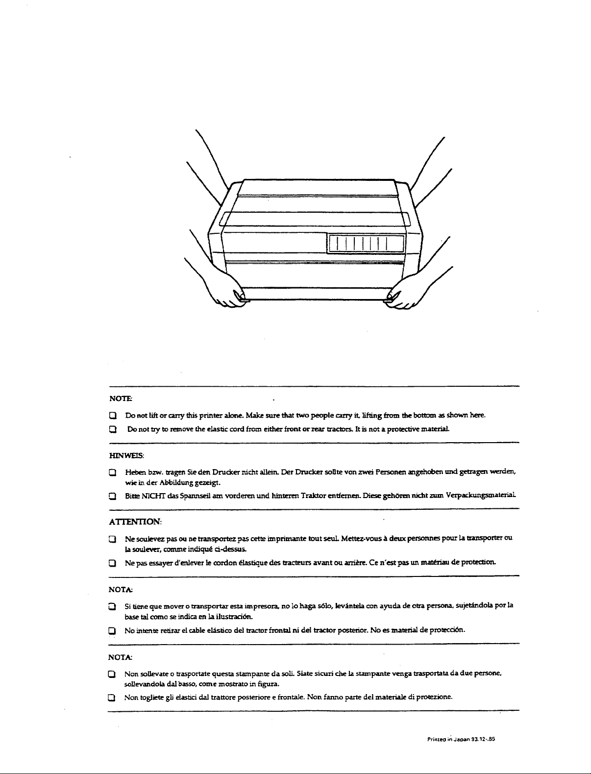
Because the printer weighs approximately 65 pounds, you should
not lift or carry it by yourself. Two people should carry it by the
bottom.
Checking the parts
Check to see that you have the parts shown below and that
nothing has been damaged during transportation.
cross-head
screwdriver
connector lock nuts
ribbon cartridge
power cable
After you unpack the printer, store the packaging materials in
case you ever need to transport the printer.
1-2
Setting Up the Printer
Page 14
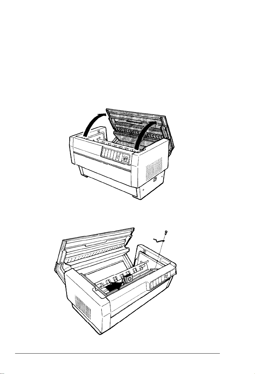
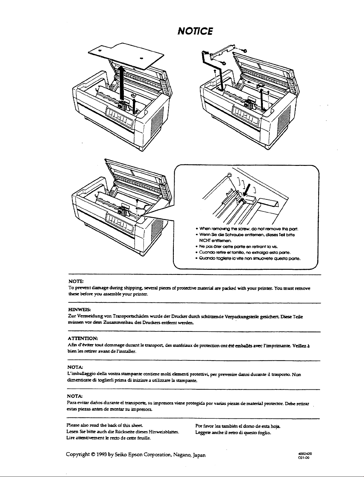
Removing the protective materials
The printer is protected during shipping by several pieces of foam
packaging, two brackets, and a carriage support bar. These
protective items must be removed before you turn on the printer.
After removing the protective materials as described below, store
them with the other packaging material.
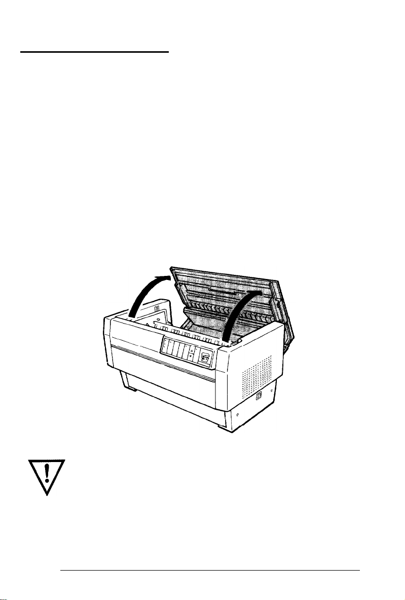
Open the printer’s top cover and remove the foam packaging
1.
material.
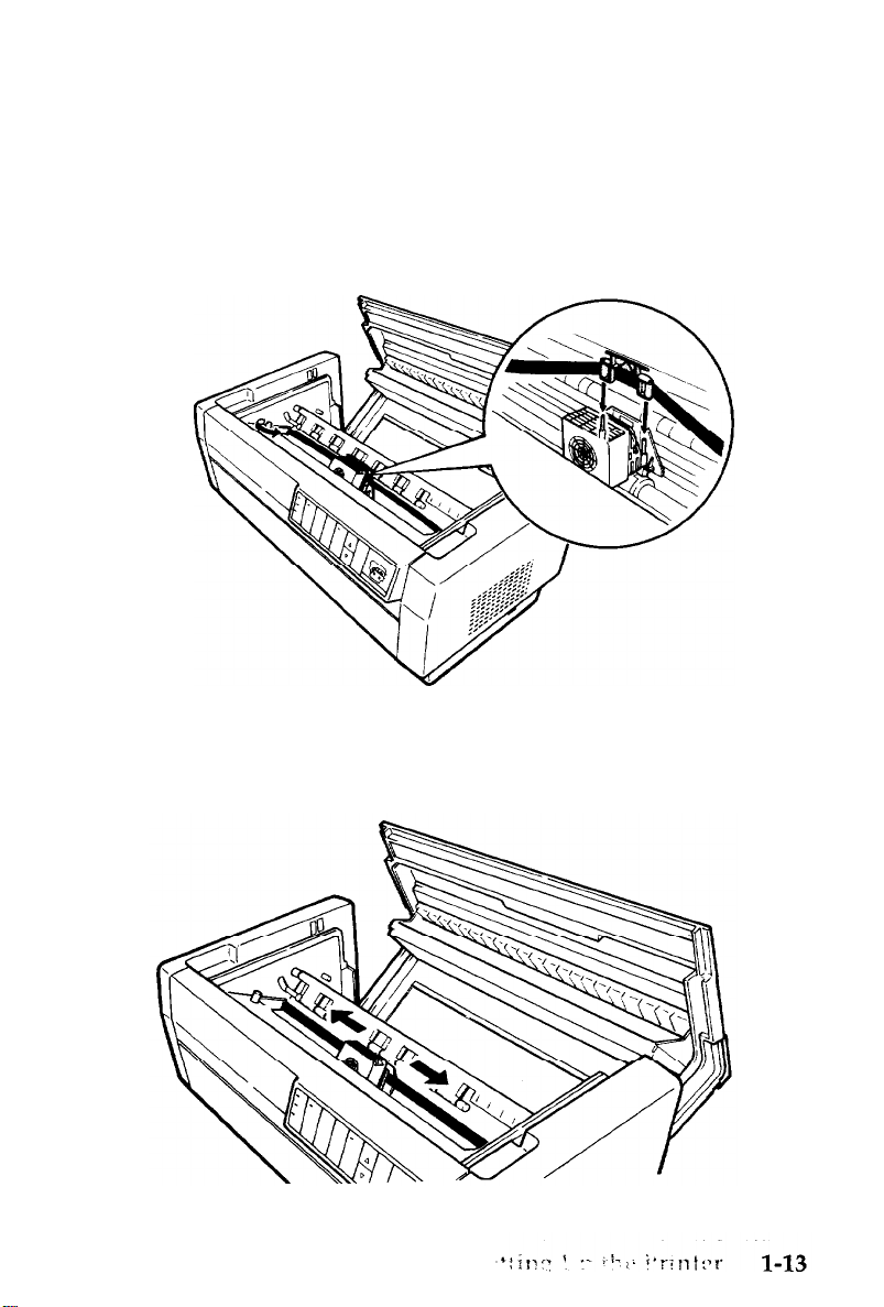
Using the cross-head screwdriver, remove the carriage support
2.
bar and slide the print head to the middle of the printer.
Setting Up the Printer
1-3
Page 15
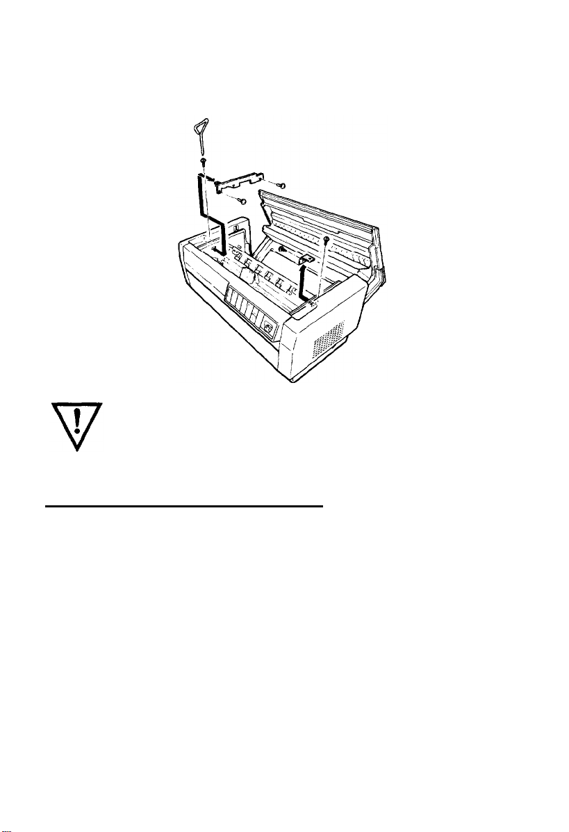
Use the cross-head screwdriver to remove the two screws and
3.
the two locking brackets from the inside of the printer.
WARNING: Be sure to remove all protective materials
before you turn on the printer.
Choosing a Place for the Printer
When you select a location for your printer, keep the following in
mind:
Place the printer on a flat, stable surface.
l
Place the printer close enough to the computer for its cable to
l
reach.
Leave plenty of room around the printer for your front and
l
rear stacks of continuous paper as well as your printed output.
Use a grounded outlet; do not use an adapter plug.
l
1-4
Setting Up the Printer
Page 16
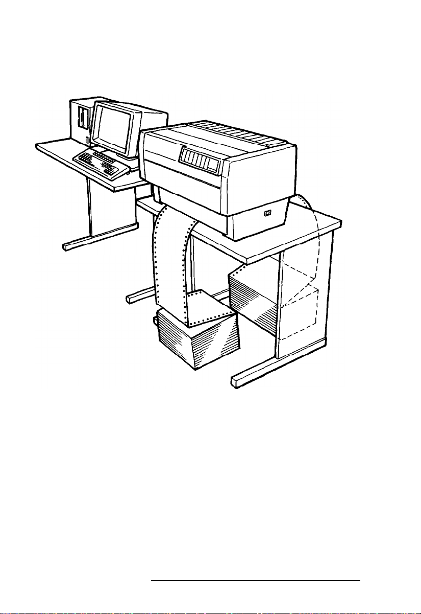
The illustration below shows a good printer location.
An optional printer stand designed for the DFX-5000 is also
available. See your Epson dealer for details.
Setting Up the Printer
1-5
Page 17

WARNING:
l Avoid locations that are subject to direct sunlight,
excessive heat, moisture, or dust.
l Avoid using electrical outlets that are controlled by
wall switches or automatic timers. Accidental
disruption of power can wipe out information in
both your computer’s memory and your printer’s
memory.
l
Avoid using outlets on the same circuit with large
motors or other appliances that might disturb the
power supply.
l
Keep the entire computer system away from
potential sources of interference, such as
loudspeakers or the base units of cordless
telephones.
A Look at Your Printer
Now that you’ve unpacked the DFX-5000, you may want to use
the following information for reference as you assemble and test
the printer. This section includes an illustration that shows you
the printer’s various parts. It also gives you a close-up look at the
control panel and indicator lights. See Chapters 2 and 3 for more
detailed information on operating your printer.
1-6
Setting Up the Printer
Page 18
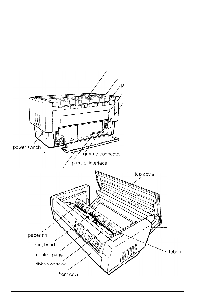
The printer parts
The following illustration gives you a detailed view of the
printer and the names of the important parts. You can refer to
this illustration when you set up and operate the printer. This
illustration is also on the inside back cover of this manual.
tear-off edge
paper separator cover
aper separator
back flap
serial interface
interface cover
w
Setting Up the Printer
paper
platen
mask
1-7
Page 19
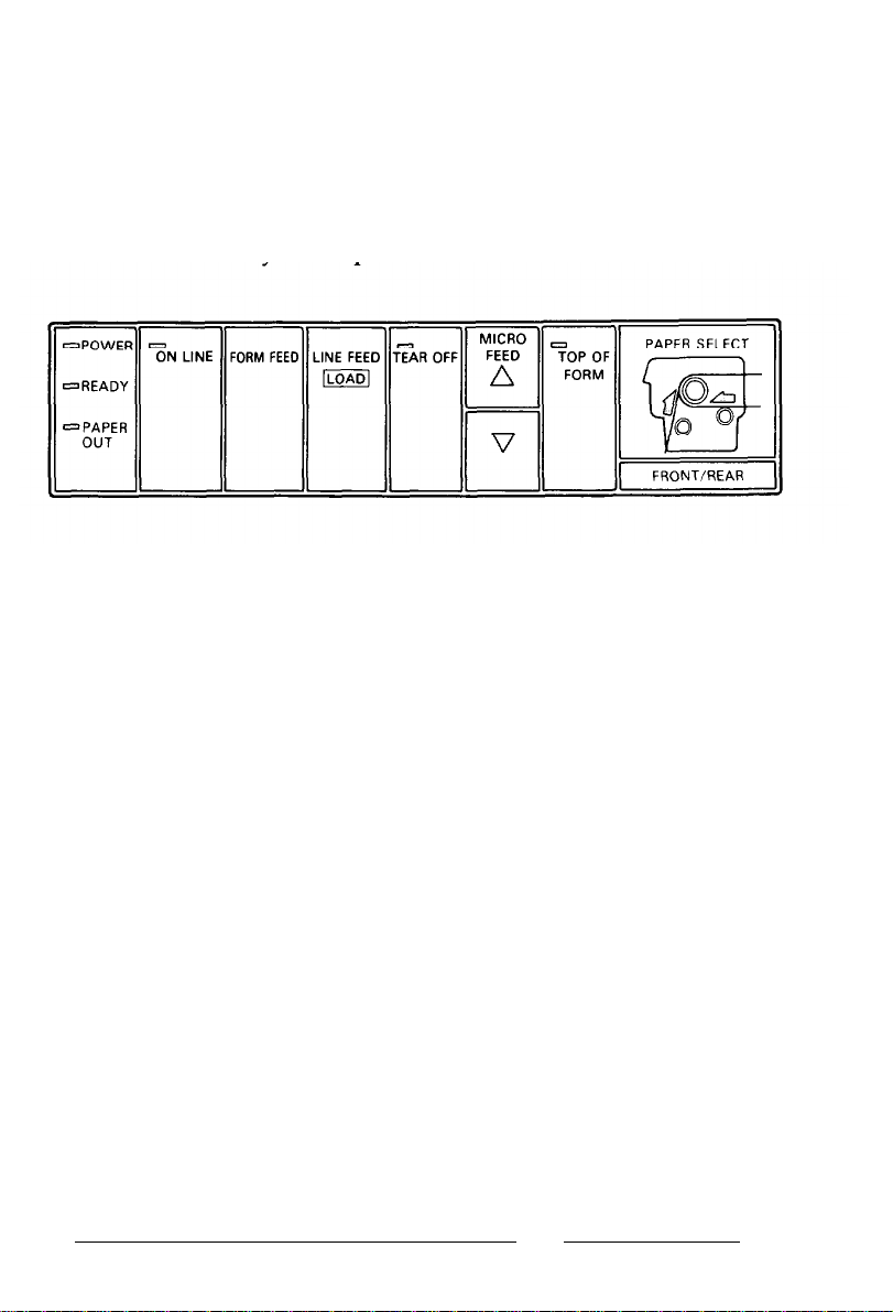
Control panel indicator lights
The indicator lights on the control panel let you check the current
status of the printer. Below is an illustration of the control panel
lights and a description of their functions. These functions are
described more fully in Chapters 2 and 3.
POWER
READY
PAPER OUT
ON LINE
TEAR OFF
TOP OF FORM
PAPERSELECT
On when the POWER switch is on and power is
supplied to the printer.
On when the printer is on line and ready to
accept input data. This light flickers during
printing.
On when the printer is out of paper.
On when the printer can receive and print data
from the computer.
On when the printer is in tear-off mode.
On when the printer is in top of form mode.
Front tractor arrow: Green when the front
tractor is selected and paper is loaded. Red
when the front tractor is out of paper.
Rear tractor arrow: Green when the rear tractor
is selected and paper is loaded. Red when the
rear tractor is out of paper.
1-8
Setting Up the Printer
Page 20
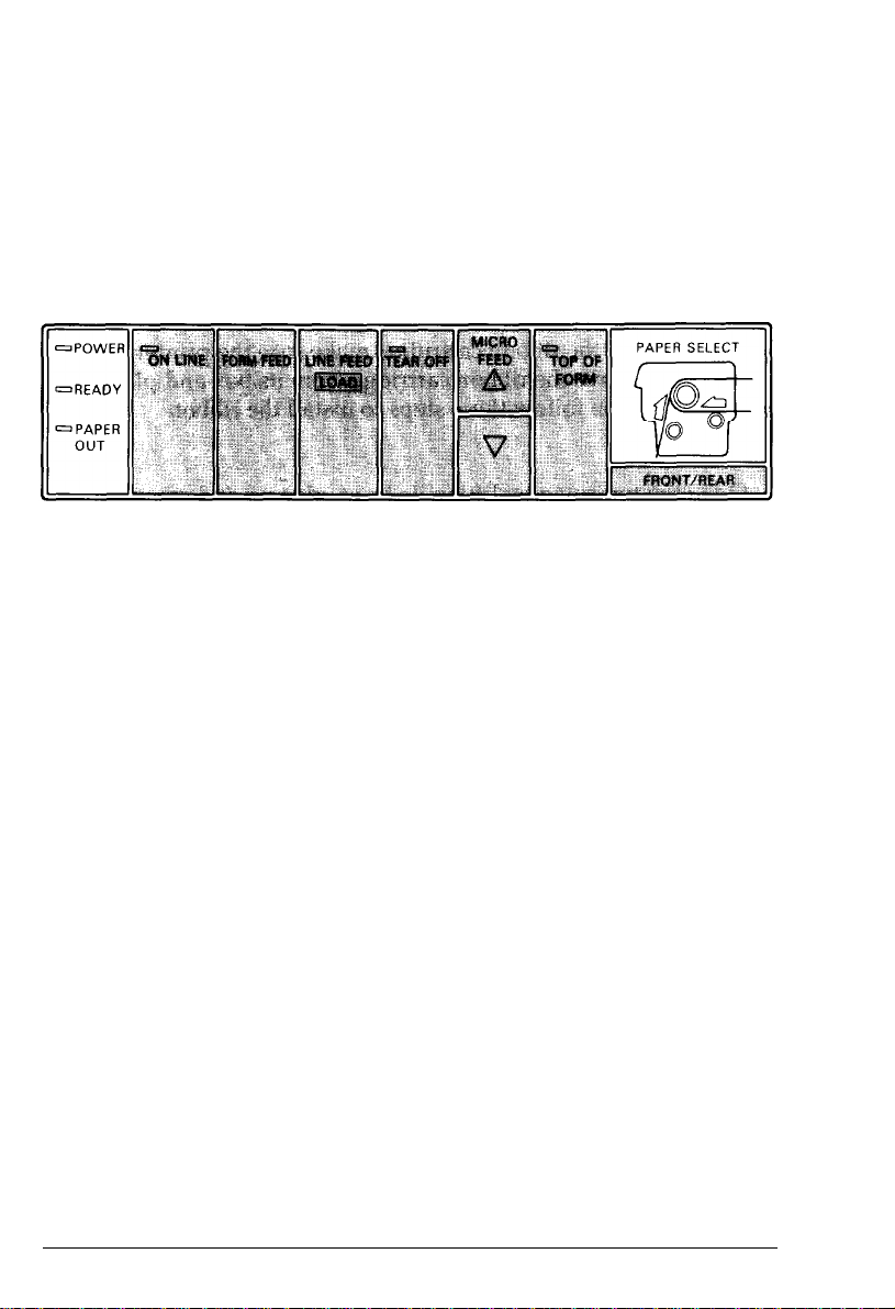
Control panel buttons
The buttons on the control panel let you control most of the
printer’s operations, Below is an illustration of the control panel
buttons and a description of their functions. These functions are
described more fully in Chapters 2 and 3.
ON LINE
FORM FEED
LINE FEED/LOAD
TEAR OFF
MICRO FEED
TOP OF FORM
FRONT/REAR
Controls the printer’s on line/off line status.
Advances paper to the top of the next page
when the printer is off line.
Advances paper one line when the printer is off
line. (Feeds paper continuously if the button is
held down.) This button can also be used to load
paper when the printer is on line. See Chapter 2
for details.
Advances paper to its tear-off position and then
feeds the paper back to the top of form position.
Advances or reverses paper in 1/216-inch
increments when the printer is off line. These
buttons are used to adjust the top of form and
tear-off positions.
Enters and exits the top of form mode when the
printer is off line.
Selects the front or rear tractor.
Setting Up the Printer 1-9
Page 21
Assembling the Printer
Since the printer comes almost completely assembled from the
factory, all you need to do is install the ribbon cartridge and
attach the power cord.
Installing the ribbon cartridge
Before installing the ribbon cartridge, make sure the printer is
turned off. Remove the ribbon cartridge from its box and plastic
wrapper and then follow these steps to install the ribbon
cartridge:
1.
Open the top cover by lifting its front edge up and away
from you.
1-10
WARNING:
printer is turned on because this can damage the
printer. Also, if you have been using the printer, the
print head may be hot; let it cool for a few minutes
before touching it.
Setting Up the Printer
Never move the print head while the
Page 22
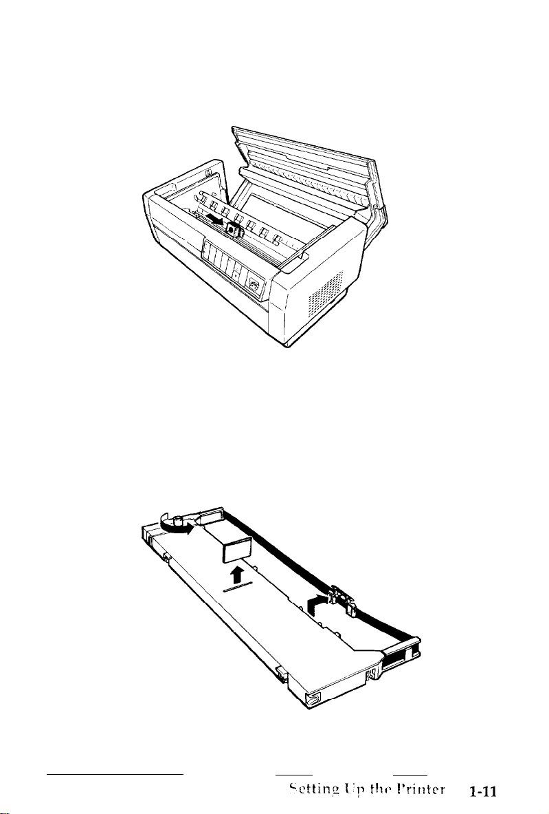
2.
Slide the print head to the middle of the printer.
3.
Remove the plastic separator from the middle of the ribbon
cartridge. (You will not need the separator again and can
discard it.) Next, detach the ribbon guide from the cartridge
and turn the ribbon-tightening knob in the direction of the
arrow to take up any slack in the ribbon.
Page 23
4.
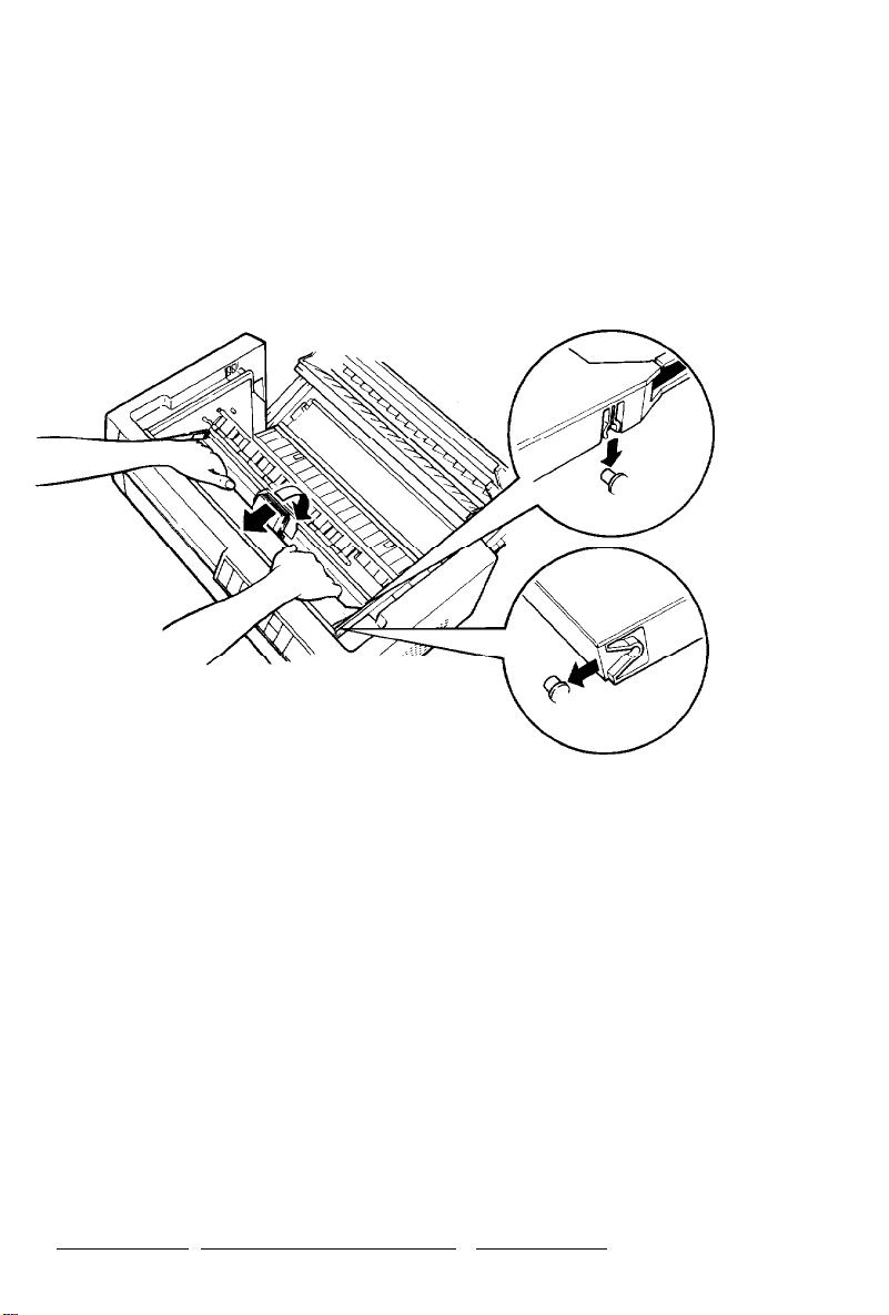
Hold the ribbon cartridge with both hands and lower it into the
printer as shown below. Pulling the cartridge toward you,
slide the hooks nearest you over the corresponding two pins in
the printer. Then push the cartridge down into position until
the other two hooks snap into place over the mounting pins in
the printer.
5.
Press lightly on both sides of the cartridge to make sure the
hooks are properly inserted.
1-12
Setting Up the Printer
Page 24
6.
Insert the ribbon guide over the metal pins on each side of the
print head as shown below. The smaller end of the guide
should be on top, with its angled edge toward the platen. Turn
the ribbon-tightening knob again to remove any slack in the
ribbon.
7.
Slide the print head from side to side to see that it moves
smoothly and that the ribbon is not twisted or creased.
Page 25
8.
Close the printer’s top cover.
Attaching the power cable
Follow these steps to attach the power cable:
1.
Check the label on the printer’s rear panel to see if the voltage
required by the printer matches that of your electrical outlet. If
it does not match, contact your Epson dealer without
connecting the power cable.
1-14
Setting Up the Printer
Page 26
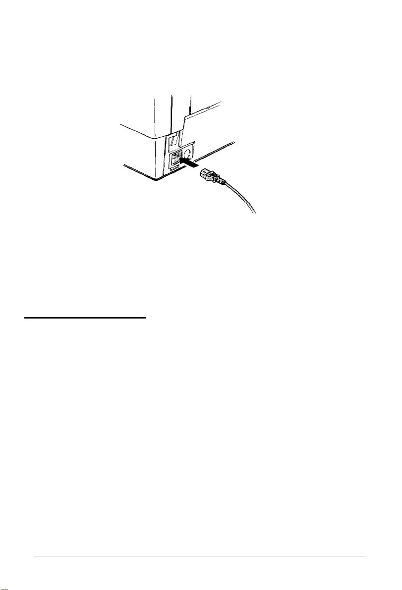
2.
Plug the power cable into the AC inlet on the printer’s rear
panel.
Note: If you move to another country, you may need to change
the voltage of the printer. See your dealer for information.
Testing the Printer
Now that your printer is fully assembled, you can use your
printer’s built-in test function to be sure the printer is working
correctly before you connect it to a computer.
Before performing the test, you need to plug in your printer and
load paper.
Plugging in the printer
Follow these steps to plug in the printer:
1.
Make sure the printer is turned off. (The zero (0) on the power
switch should be visible.)
2. Plug the power cable into a properly grounded electrical outlet.
Setting Up the Printer 1-15
Page 27
WARNING: Whenever you turn off the power, wait at
least five seconds before turning it back on. Rapid
switching on and off can damage the printer.
Loading paper for the self test
Next, you need to load continuous paper that is at least 15 inches
wide. To load paper, follow these steps:
WARNING: Use paper that is at least 15 inches wide for
I
the self test to keep the print head from printing directly
.
77
1.
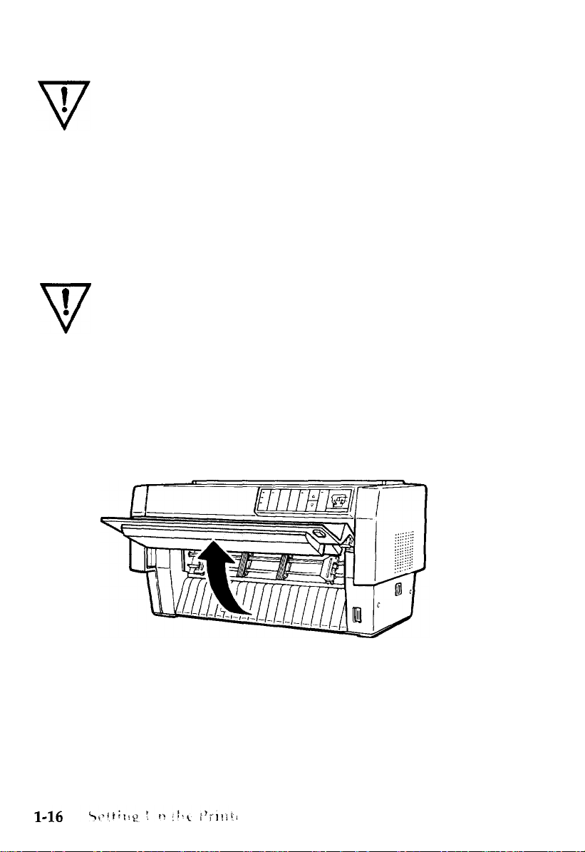
onto the platen.
Open the printer’s front cover by lifting its bottom edge up and
toward you, as shown below.
Page 28

2.
Release the sprocket lock levers on both the right and left
sprocket units by pulling each lever down.
3.
Slide the left sprocket unit all the way to the left. Lock it into
place by pushing the sprocket lock lever up.
Page 29
4.
Now slide the right sprocket unit to approximately
width of your paper. (Do not lock it in place yet.)
5.
Slide the two paper supports so that they are spaced evenly
between the sprocket units.
match the
1-18
Setting Up the Printer
Page 30
6. Open both sprocket covers.
7.
Be sure your paper has a clean, straight edge, and then fit the
first five holes in the paper over the pins of the sprocket units
as shown below. The side of the paper that you want to print
on should be facing you. Now close the sprocket covers.
Setting Up the Printer
1-19
Page 31

8.
Slide the right sprocket unit so that the paper is straight
no wrinkles. Lock the sprocket unit in place by pushing
sprocket lock lever up.
9.
Close the printer’s front cover.
and has
the
Page 32

WARNING:
Before turning on the printer, be absolutely
sure you have removed all protective materials. Turning
on the printer while the print head cannot move may
seriously damage the mechanism.
10. Turn on the printer. The print head moves to the middle of the
printer and the POWER and PAPER OUT lights come on. Also,
either the front or rear tractor arrow on the PAPER SELECT
indicator lights up.
:.
:
:
:
:.
:
7
c
11. Press the LINE FEED/LOAD button to load your paper. (If the
paper does not load, the front tractor may not be selected.
Press the FRONT/REAR button to select the front tractor. This
loads the paper automatically.)
12. After the paper loads, turn off the printer.
Setting Up the Printer
1-21
Page 33

Running the self test
The self test prints out the settings of the printer’s DIP switches
and the characters in the printer’s memory. The test can be run in
either draft,, high-speed draft, or near letter quality (NLQ) mode.
Your printer’s default setting is high-speed draft mode. To run the
self test in high-speed draft mode, follow these steps:
Caution: Always use paper that is at least 15 inches wide
when running the printer’s self test.
1.
While holding down the LINE FEED button, turn on the printer.
After printing starts, release the button.
A list of your printer’s settings is printed first, followed by a
series of characters. Here is part of a typical self test printout
in high-speed draft.
2.
The self test continues until the paper runs out or until you
press the ON LINE button. If the test results are satisfactory and
you wish to stop the test, press the ON LINE button to take the
printer off line, and then turn off the printer.
1-22
Setting Up the Printer
Page 34

If you want to run the self test in NLQ mode, follow Steps 1 and 2
above using the FORM FEED button instead of the LINE FEED button.
Here is part of a self test printout run in NLQ mode:
Country
U.S.A.
Page length (inch) 11
SWlsw2sw2sw2sw2-
-./0123456789:;<=>?@ABCDEFGHIJKLMNOF
&‘()*+,~./0123456789:;<=>?@ABCDEFGHIJKLMNOPQ
‘()a+,--./0123456789:;
<=>?@ABCDEFGHIJKLMNOPQR
To run the self test in the normal draft mode, you need to first
select normal draft mode by changing your printer’s DIP switch
settings. This procedure is described in the section on setting DIP
switches in Chapter 3. Once the printer is set for the normal draft
mode rather than high-speed draft, you can run the self test by
following the same procedure as for high-speed draft. Here is part
of a self test printout run in normal draft mode:
Setting Up the Printer
1-23
Page 35

Connecting the Printer to Your Computer
If the self test printed correctly, you are now ready to connect the
printer to your computer.
Your printer has two separate interface connections: a
Centronics®-compatible parallel interface and an RS-232C
compatible serial interface. If you are not sure which one is
required by your computer, check your computer manual.
parallel interface
If you have a suitable shielded cable, you should be able to
connect the printer immediately. If you have one of the few
computers that requires a different type of interface, you should
be able to use one of the optional interfaces described in Chapter 6.
The parallel interface is the printer’s default setting. If you need to
use the built-in serial interface, be sure to change the DIP switch
settings as shown in Chapter 3.
Page 36

WARNING: Never plug more than one interface cable
into the printer at one time. This may damage the printer.
Connecting the parallel interface
Follow these steps to connect your computer’s parallel interface
cable to the printer:
1.
Turn off both your printer and computer.
2.
Open the printer’s interface cover by grasping it by the
handholds on each side.
Page 37

Plug the cable connector securely into the parallel interface (the
3.
socket on the left).
4.
Squeeze the wire clips together until they lock in place on either
side of the connector. If your cable has a ground wire, connect
it to the printer’s ground connector.
1-26
Setting Up the Printer
Page 38

5.
Open the plastic clamp to the right of the parallel and serial
interfaces by pressing on its top tab. Insert the cable in the
plastic clamp and close the clamp, as shown below.
6. Close the interface cover.
Caution: Always close the interface cover before using the
printer.
Setting Up the Printer
1-27
Page 39

7.
Plug the other end of the cable into the computer. (If there is a
ground wire at the computer end of the cable, attach it to the
ground connector at the back of the computer.)
Connecting the serial interface
Before using the printer’s serial interface, you need to select serial
communication by changing the printer’s DIP switch settings. You
may also need to change two other serial interface settings, baud
rate and parity, before your printer and computer can
communicate properly. See the section on setting DIP switches in
Chapter 3 for more information.
The following steps show you how to connect your computer’s
serial interface cable to the printer. If the connector on your cable
has screws that need to be tightened with a screwdriver, you may
need both a cross-head screwdriver and a flat-blade screwdriver
to connect the cable.
1.
Turn off both the printer and computer.
2.
Open the printer’s interface cover by grasping it by the
handholds on each side.
1-28
Setting Up the Printer
Page 40

Plug the cable connector securely into the serial interface (the
3.
socket on the right). If your cable has a ground wire, connect it
to the printer’s ground connector.
If your cable connector has screws that you have to tighten using a
4.
screwdriver, you may need to open the top cover of the printer guide
for easier access.
Setting Up the Printer
1-29
Page 41

5. Insert a screwdriver through the two holes and fasten the
the cable connector.
screws of
Note: The screws on the serial interface cable connector must
fit into connector lock nuts on the printer. If the screws on your
serial interface cable do not fit, remove the connector lock nuts
on the printer and replace them with the optional ones
supplied with the printer.
6.
Confirm that the connector is secure
1-30
Setting Up the Printer
Page 42

7.
Open the plastic clamp on the right by pressing on its top tab.
Insert the cable in the plastic clamp, as shown below.
8. Close the interface cover.
Caution: Always close the interface cover before using the
printer.
Plug the other end of the cable into your computer. (If there is a
9.
ground wire at the computer end of the cable, attach it to the
ground connector at the back of the computer.)
Setting Up the Printer
1-31
Page 43

Setting Up Your Application Software
Now that you have set up and tested the DFX-5000, you can start
using it with your application software programs.
Most software programs let you specify the type of printer you
are using so that the program can take full advantage of the
printer’s features. If your application program has an installation
or setup procedure that lets you select your printer from a list of
printers, choose the Epson DFX-5000 printer. If the list does not
include the DFX-5000, choose one of the following printers, listed
in order of preference:
FX-850/1050
FX-86e/286e
FX-85/185
FX-80/100
EX-800/1000
FX
LX
Epson printer
9-pin printer
Standard printer
Draft printer
Note: To use all the features of the DFX-5000, it is best to use a
program with the DFX-5000 on its menu. If your software
program does not list the DFX-5000, contact the software
manufacturer to see if an update is available.
Page 44

Chapter 2
Loading and Using Paper
Using the Two-Tractor System
Positioning the paper supply
Loading Paper onto the Front Tractor
Loading Paper onto the Rear Tractor . . . . . . . . . . . . . . . . . . . . . . . 2-9
Adjusting the Top of Form Position . . . . . . . . . . . . . . . . . . . . . . . . 2-17
Adjusting the Printing Position . . . . . . . . . . . . . . . . . . . . . . . . . . . . 2-19
Using Automatic Tear-Off . . . . . . . . . . . . . . . . . . . . . . . . . . . . . . . . . 2-20
Switching Between Front and Rear Tractors . . . . . . . . . . . . . . . . . 2-24
Changing the Paper. . . . . . . . . . . . . . . . . . . . . . . . . . . . . . . . . . . . . . . 2-26
Printing on Special Paper
Using multi-part forms
Using labels
...........................................
.............................
............................
. . . . . . . . . . . . . . . . . . . . . . 2-3
.................................
.................................
2-2
2-2
2-30
2-30
2-31
Page 45

Using the Two-Tractor System
The DFX-5000’s paper handling system consists of a front push
tractor and a rear push tractor. Both tractors are easy to load and
operate, and both accommodate a wide variety of paper types,
including labels and multi-part forms. The printer automatically
adjusts to the thickness of your loaded paper, so you don’t need to
make any manual adjustments for paper thickness settings.
You can use any width continuous paper, from 4 to 16 inches
wide. However, the width of your printed text must be narrower
than the size of the paper you are using-otherwise, you might
damage the printer by printing on the platen.
If you are going to use more than two types of paper, it’s best to
load the paper you use most often onto the rear tractor. That way
you can reserve the front tractor, which is easier to reach, for the
paper you change more frequently. Always use the front tractor
for printing on labels.
Positioning the paper supply
Since the DFX-5000 can be loaded with continuous paper from
both the front and the rear, be sure to leave enough room around
the printer for the two stacks of fresh paper as well a third stack of
printed output. It is also important to keep both stacks of fresh
paper aligned with the printer so that the paper can feed smoothly
into the printer.
2-2
Loading and Using Paper
Page 46

The following illustration shows three ways to position your
printer and paper: with the front tractor loaded, with the rear
tractor loaded, and with both tractors loaded.
Note: Make sure that your stack of printed pages does not
interfere with the rear tractor’s paper supply.
Loading Paper onto the Front Tractor
The following steps show you how to load paper onto the front
tractor.
1. Turn off the printer.
2.
Open the printer’s front cover by lifting its bottom edge up
and toward you, as shown below.
Page 47

3.
Release the sprocket lock levers on both the right and left
sprocket units by pulling each lever down.
4.
Slide the left sprocket unit all the way to the left. Lock it in
place by pushing the sprocket release lever up.
2-4
Loading and Using Paper
Page 48

5.
Now slide the right sprocket unit to approximately
width of your paper. (Do not lock it in place yet.)
Slide the two paper supports so that they are spaced evenly
6.
between the two sprocket units.
match the
Loading and Using Paper
2-5
Page 49

7.
Open both sprocket covers.
8.
Fit the first five holes in the paper over the pins of the sprocket
units as shown below. (The side of the paper that you want to
print on should be facing you, and the paper should have a
clean, straight edge.) Now close the sprocket covers.
2-6
Loading and Using Paper
Page 50

Slide the right sprocket unit so that the paper is straight and has
9.
no wrinkles. Lock the sprocket unit in place by pushing the
sprocket release lever up.
10. Close the printer’s front cover. The paper is now loaded to the
standby position.
Loading and Using Paper
2-7
Page 51

11. Turn on the printer. The print head moves to the middle of the
printer and the POWER and PAPER OUT lights go on. Also,
either the front or rear tractor arrow on the PAPER SELECT
indicator lights up, depending on which tractor was selected
when the printer was turned off last.
12. Check the PAPER SELECT indicator to see which tractor is
selected:
If the front tractor indicator arrow is lit up, press the
l
2-8
LINE FEED/LOAD
Loading and Using Paper
button to load the paper.
Page 52

l
If the rear tractor indicator arrow is lit up, make sure the
printer is off line and then press the FRONT/REAR button to
switch to the front tractor. When the printer switches
tractors, it also loads the paper automatically.
13. Press the ON LINE button to put the printer on line so it is ready
to print. The paper is now loaded to the top of form position.
If it looks like the printing will start too high or low on the
page, see page 2-17 for instructions on adjusting the top of
form position.
Loading Paper onto the Rear Tractor
The following steps show you how to load paper onto the rear
tractor. You do not need to remove the paper from the front
tractor first because the printer does this for you when you select
the rear tractor.
1. Turn off the printer.
Loading and Using Paper
2-9
Page 53

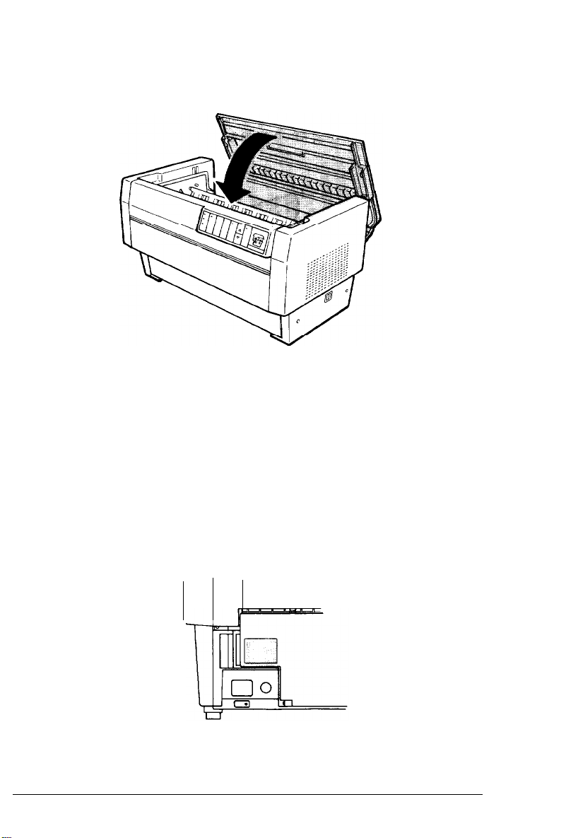
2.
Open the printer’s top cover by lifting its front edge up and
away from you, as shown below.
3.
The top cover has two flaps that can be opened independently.
One flap is on the top part of the cover and the other, shown
below, is on the back side. Open the back flap.
2-10
Loading and Using Paper
Page 54

Release the sprocket lock levers on the rear tractor’s right and
4.
left sprocket units by pushing each lever back-
place
Page 55

6.
Now slide the right sprocket unit to approximately match the
width of your paper. (Do not lock it in place yet.)
7.
Slide the two paper supports so they are spaced evenly between
the two sprocket units.
2-12
Loading and Using Paper
Page 56

8. Open both sprocket covers.
With the side of the paper you want to print on facing down,
9.
insert your paper through the opening at the rear. You may
find it easier to load the paper by standing to the side of the
printer. That way you can feed the paper into the rear opening
with one hand and pull it through with the other.
Note: Make sure your paper has a clean, straight edge.
Loading and Using Paper
2-13
Page 57

10. Fit the first five holes in the paper over the pins of the sprocket
units as shown below. Now close the sprocket covers.
11. Slide the right sprocket unit to a position so that the paper is
straight and has no wrinkles. Lock the sprocket unit in place
by pulling the sprocket lock lever forward.
2-14
Loading and Using Paper
Page 58

12. Close the top cover and the back flap. The paper is now loaded
to the standby position.
13. Turn on the printer. The print head moves to the middle of the
printer and the POWER and PAPER OUT lights go on. Also,
either the front or rear tractor arrow on the PAPER SELECT
indicator lights up, depending on which tractor was selected
when the printer was turned off last.
_._
Loading and Using Paper
2-15
Page 59

14. Check the PAPER SELECT indicator to see which tractor is
selected:
l
If the rear tractor arrow is lit up, press the LINE FEED/LOAD
button to load the paper.
l If the front tractor arrow is lit up, make sure the printer is
off line and then press the FRONT/REAR button to switch to
the rear tractor. When the printer switches tractors, it also
loads the paper automatically.
15. Press the ON LINE button to put the printer on line so it is ready
to print. The paper is now loaded to the top of form position.
If it looks like the printing will start too high or low on the
page, see the next section for instructions on adjusting the top
of form position.
2-16
Loading and Using Paper
Page 60

Adjusting the Top of Form Position
The top of form position is the position the printer feeds the paper
to when it loads the paper or performs a form feed. This position
is important because it determines where the printing begins on
each page.
If the printing is too high or low on the page, you can reset the top
of form position by following the steps outlined below. The
printer remembers the new top of form position even after the
printer is turned off, reset, or initialized. (The printer remembers
separate top of form positions for the front and rear tractors.)
You can temporarily change the top of form position by adjusting
the position when you are not in the top of form mode or by
changing the printing position in the middle of a page (see the
next section). The printer remembers the temporary top of form
position until the next time you load paper or switch tractors.
The following steps show you how to reset the top of form
position. Before you start, make sure the printer is turned on and
the desired tractor is selected (the corresponding tractor arrow
should be lit up).
WARNING:
labels are loaded in the printer, use the
(top)
MICRO FEED
To adjust the top of form position when
forward-feeding
button only. Labels must never be fed
backward through the printer.
1.
Make sure the printer is off line.
2.
Press the TOP OF FORM button to enter the top of form mode.
The printer beeps once, and the TOP OF FORM light starts
flashing. Also, the printer advances the paper so that the top of
form position is lined up with the red line on the clear
plastic ribbon mask.
Loading and Using Paper
2-17
Page 61

3. The red line on the ribbon mask shows you where the
bottom edge of your first line of text will print. This position is
based on the first printable line of text. If your software inserts
a top margin of five lines, your text will actually print five
lines below the top of form position. Use the MICRO FEED
buttons to feed the paper to the desired top of form position.
0
.-__---~----_---___--__---~-
--0
i
Note: The red line on the ribbon mask can be used as a
reference only when you are in the top of form mode. At all
other times your top of form position is hidden behind the
print ribbon.
4.
Press the TOP OF FORM button again to exit the top of form
mode and save your new top of form position. (If you want
to exit the top of form mode without saving your new top of
form setting, press the ON LINE button instead of the
TOP OF FORM
2-18
Loading and Using Paper
button.)
Page 62

5.
Press the ON LINE button to put the printer on line. The printer
remembers your new top of form position even after the
printer is turned off, reset, or initialized.
Adjusting the Printing Position
For some of your printing, such as preprinted forms and labels,
the alignment of your text is critical-not just at the top of form
position, but in the middle of the page as well. Rather than
calculate where your text will fall based on the top of form
position, there’s an easier way to position your printing.
When you move the printing position, you temporarily change the
top of form position by the same amount. For example, if you
adjust the printing in the middle of a page so that it falls a
half-inch lower, the next page will begin printing a half-inch
lower as well. The printer remembers this temporary top of form
position until the next time you load paper or switch tractors.
Follow these steps to adjust your printing position:
1.
Start printing your document. When you get to the text that
needs to be aligned at a particular spot on the page, press the
ON LINE button to stop printing.
Note: You may find it easier to stop your document at the right
spot if you use a slower printing speed. See the section in
Chapter 3 on selecting the NLQ mode with DIP switches.
2.
The printing position is normally hidden behind the ribbon. To
see the position better, press the TOP OF FORM button. This
advances the paper slightly so that the printing position lines
up with the red line on the clear plastic ribbon mask.
Loading and Using Paper
2-19
Page 63

3.
Use the MICRO FEED buttons to position your paper to where
you want the bottom edge of your next line of text to fall. If
you are printing on labels, use only the forward-feeding (top)
MICRO FEED
4.
When you are finished, press the ON LINE button to exit the top
of form mode. (Do not press the TOP OF FORM button to exit
the top of form mode. If you do, the printer remembers your
new printing position as the new top of form position instead.)
button.
Using Automatic Tear-Off
The TEAR OFF button lets you feed the perforation of your paper to
the printer’s tear-off edge when you are finished printing. This
makes it easier to tear off the last printed sheet and saves paper
normally lost between documents.
If you need to adjust the position of the perforation so that it
meets the printer’s tear-off edge, you can reset the tear-off
position by entering the tear-off mode and using micro-feed. The
printer remembers this new tear-off position and uses it as a
reference point for feeding the paper. (The printer remembers
separate tear-off positions for the front and rear tractors.)
The following steps show you how to use the automatic tear-off
feature. Before you start, make sure that the printer is turned on
and the desired tractor is selected.
2-20
WARNING:
If labels are fed backward,
Loading and Using Paper
Never
use
the
TEAR OFF
they
button with labels.
may jam the printer.
Page 64

1.
If the printer is on line, press the ON LINE button to take it off
line. Now open the paper separator cover (the flap on the top
part of the printer’s top cover). This exposes the printer’s
tear-off edge.
2.
Press the TEAR OFF button to enter the tear-off mode. The
TEAR OFF light goes on and the printer feeds the paper’s
perforation to the printer’s tear-off edge.
Loading and Using Paper
2-21
Page 65

If you need to adjust the position of the perforation so that it
3.
meets the printer’s tear-off edge, press the MICRO FEED buttons
to feed the paper forward or backward in 1/216th-inch
increments. (You can also hold down either MICRO FEED button
to feed the paper continuously.)
Note: You can reset the tear-off position only when you are in
the tear-off mode (after you have pressed the TEAR OFF button
once and the TEAR OFF light is on). The printer remembers the
new tear-off position even after the printer is turned off, reset,
or initialized.
2-22
Loading and Using Paper
Page 66

4.
Tear off the page using the tear-off edge on the printer’s top
cover.
5.
Press the TEAR OFF button to feed the paper back to the top of
form position, and then press the ON LINE button to put the
printer on line so it is ready to print. (Or instead, press the
ON LINE button to feed the paper back and put your printer
on line at the same time.)
WARNING: Always tear off the printed document
before you feed the paper back to the top of form
position. Never feed paper backward more than one
page.
Loading and Using Paper
2-23
Page 67

Switching Between Front and Rear Tractors
You can easily switch between paper loaded on the front tractor
and paper loaded on the rear tractor. The following steps describe
the procedure for switching from the front tractor to the rear
tractor, but you can follow the same steps to switch from the rear
tractor to the front tractor. (To switch tractors when the optional
pull tractor is installed, see Chapter 6.)
WARNING: Never switch between tractors when labels
are already loaded in the printer.
remove the labels first by tearing off the fresh supply
below the tractor and pressing
to eject the remaining labels.
Before you start, make sure the printer is turned on and that the
front tractor is selected (the front tractor arrow on the PAPER
SELECT indicator should be lit up). If you are in the middle of
printing a document, wait for the printer to finish printing before
you switch tractors. Then follow these steps:
1.
If there is no paper loaded in the rear tractor, load paper to the
standby position (the first five pins of the sprocket units), as
described in Steps 1 through 13 on page 2-9.
Instead, completely
FORM FEED
or
LINE FEED
2-24
Loading and
Using
Paper
Page 68

2.
If you have a printed document still in the printer, or excess
paper that has been fed through the printer, use the automatic
tear-off feature described in the previous section to tear off the
document or excess paper.
WARNING: Always tear off the printed document and
any excess paper that has been fed through the printer
before switching tractors. Never feed more than one
page backward through the printer.
3.
If the printer is on line, press the ON LINE button to take it off
line.
Loading and Using Paper
2-25
Page 69

4.
Press the FRONT/REAR button to switch to the rear tractor. The
front-loaded paper automatically feeds back to the standby
position and the rear-loaded paper is advanced to the top of
form position.
5.
Press the ON LINE button to put the printer back on line so it is
ready to print.
Changing the Paper
The following steps describe the procedure for changing paper on
the front tractor, but you can follow the same steps when you
change the paper on the rear tractor.
Before you start, make sure the printer is turned on and the front
tractor is selected. (If you are changing the paper on the rear
tractor, the rear tractor should be selected instead.)
2-26
Loading and Using Paper
Page 70

WARNING: Never change paper using the following
1
procedure if labels are already loaded in the printer.
l
Q
1.
Instead, completely remove the labels first by tearing
off the fresh supply below the tractor and pressing
FORM FEED
Then load the new paper as described earlier in this
chapter in the sections on loading paper.
If you have a printed document still in the printer, use the
automatic tear-off feature described on page 2-20 to tear off the
document or excess paper.
or
LINE FEED
to eject the remaining labels.
WARNING: Always tear off printed documents before
1
changing the paper. Never feed more than one page
l
Q
2.
backward through the printer.
If the printer is on line, press the ON LINE button to take it off
line.
Loading and Using Paper
2-27
Page 71

3.
Press the FRONT/REAR button to switch to the rear tractor.
The front-loaded paper automatically feeds back to the
standby position.
4.
Open the printer’s front cover. (To change the rear-loaded paper,
open the printer’s top cover and the back flap.)
2-28
Loading and Using Paper
Page 72

Open the sprocket covers and remove the paper from the
5.
tractor.
Load the new paper as described in Steps 1 through 13 on page
6.
2-3 (or for rear-loaded paper, Steps 1 through 15 on page 2-9).
Loading and Using Paper
2-29
Page 73

Printing on Special Paper
The DFX-5000 can print on various types of paper, including
multi-part forms and labels. It can also handle a variety of paper
thicknesses, from thin paper to six-part forms. The printer
automatically adjusts to the thickness of your paper.
When you print on multi-part forms and labels, the positioning of
your text on the page can be critical. For more information on
aligning your text, see the sections on adjusting top of form and
printing positions earlier in this chapter. You should also check
both your printer and your software page length settings before
you load labels or forms. See the section on setting page length in
Chapter 3.
If you are using labels or preprinted or multi-part forms, you may
want to use the optional pull tractor. See Chapter 6.
WARNING: When printing on multi-part forms or
labels, be absolutely sure that your printing stays within
the printable area of the paper to prevent damage to the
print head. For more information on the printable area,
see Appendix B.
Using multi-part forms
You can use multi-part forms with up to four sheets, including the
original, on the rear tractor. On the front tractor, you can use
forms with up to six sheets.
You load continuous multi-part forms the same way you load any
other type of continuous paper. Before loading multi-part forms,
however, make sure the paper has a clean straight edge and does
not separate or tear apart. See the sections on loading paper
earlier in this chapter.
2-30
Loading and Using Paper
Page 74

Using labels
When using labels in the DFX-5000, always choose the type
mounted on continuous paper with sprocket holes for use with a
tractor. Labels should be used in the front tractor only. You load
labels the same way that you load continuous paper. See the
section on loading paper onto the front tractor earlier in this
chapter.
WARNING:
reverse-feeding (bottom)
are loaded in the printer. Labels must never be fed
backward through the printer because they can easily
come off the backing and jam the printer.
Although you must never feed labels backward through the
printer, you can still use the DFX-5000’s automatic paper handling
features if you follow these precautions:
Instead of using the TEAR OFF button to remove printed labels,
take the printer off line and press the
button until the last printed label is at the point where you can
tear it off easily.
Before using the FRONT/REAR button to switch tractors or
change paper, remove the entire supply of labels first. Always
remove labels by tearing off the fresh supply at a perforation
below the tractor and then pressing the FORM FEED or LINE FEED
button to eject the remaining labels.
When adjusting the top of form or printing position, use only
the forward-feeding (top) MICRO FEED button.
Never use the
MICRO FEED
TEAR OFF, FRONT/REAR,
button when labels
FORM FEED
or
or
LINE FEED
1
a
Q
WARNING:
extreme temperatures and humidity, always use them
under normal operating conditions.
Because labels are especially sensitive to
Loading and Using Paper
2-31
Page 75

Chapter 3
Using the Printer
Operating the Control Panel . . . . . . . . . . . . . . . . . . . . . . . . . . . . . . . 3-2
Control panel indicator lights
Control panel buttons
Other control panel features . . . . . . . . . . . . . . . . . . . . . . . . . . . . . 3-7
. . . . . . . . . . . . . . . . . . . . . . . . . . . . . . . . . . 3-4
. . . . . . . . . . . . . . . . . . . . . . . . . . . 3-2
Using DIP Switches
Changing DIP switch settings
DIP switch tables
DIP switch functions
Condensed mode
Slashed zero
Character table
Input buffer
Near letter quality or draft mode
International character sets
Page length
Printing speed in draft mode
Skip over perforation
Auto line feed
Interface type and parity
Baud rate
Using Your Printer With Application Programs
A quick test
Using word processors
Using spreadsheets
............................................
......................................
...........................
.......................................
...................................
....................................
.........................................
......................................
.........................................
......................
...........................
..........................................
..........................
.................................
.......................................
.............................
...........................................
.................................
.....................................
..............
3-8
3-8
3-10
3-12
3-12
3-13
3-13
3-15
3-15
3-16
3-17
3-17
3-18
3-18
3-19
3-19
3-20
3-20
3-21
3-21
Using the Printer 3-1
Page 76

Operating the Control Panel
The DFX-5000’s control panel gives you access to several powerful
features. The control panel buttons let you control paper loading,
printing and tear-off positions, and more. The control panel lights
give you status information such as which mode you are in, which
tractor is loaded with paper, and which tractor is ready to print.
The following sections describe the functions of the control
panel’s lights and buttons.
Control panel indicator lights
The indicator lights on the control panel let you check the current
status of the printer. Below is an illustration of the control panel
lights and a description of their functions.
II
B
IzaPCIWFRII cm II
-..-.
-READY
-PAPER
OUT
II
11 MICRO 11 cma
TOP
FORM
OF
FRONT/REAR
11
aREnD”
=PAPER
OUT
I
The POWER light comes on when the power switch is on
and power is supplied to the printer.
’
oPOWER
,
m=READY
-PAPER
OUT
The READY light comes on when the printer is on line
and ready to receive data from your computer. This light
flickers during printing.
I
3-2
Using the Printer
Page 77

‘a
TEAR
OFF
I
The PAPER OUT light comes on when the printer is out of
paper. This light goes on whenever there is no paper
positioned behind the print head, even if there is paper
loaded on the tractors in the standby position.
The ON LINE light comes on when the printer is on line
and ready to receive and print data from your computer.
The TEAR OFF light comes on when the printer is in the
tear-off mode. The printer remembers any change you
make to the tear-off position when this light is on.
The TOP OF FORM light comes on when the printer is in
the top of form mode. The printer remembers any
change you make to the top of form position when this
light is on.
The front tractor arrow comes on when the front
tractor is selected. The light is green when paper is
loaded, even if the paper is in the standby
position, and red when the tractor is completely
out of paper.
The rear tractor arrow comes on when the rear
tractor is selected. The light is green when paper is
loaded, even if the paper is in the standby
position, and red when the tractor is out of paper.
Using the Printer
3-3
Page 78

Control panel buttons
The control panel buttons let you perform printer operations
quickly and easily. Most buttons work only when the printer is
off line. The exceptions to this are the ON LINE button and the
LINE FEED/LOAD
button.
oPOWER
-READY
0
PAPER
OUT
TN
LINE FORM FEED
UNE
FEED
~
li%l
MICRO
OFF
: ‘ii”
E)
TOP OF
FORM
PAPER SELECT
LJ
v
r-l
The ON LINE button controls the printer’s on line status.
Press this button to put the printer on line or take it off
line. When the printer is on line, the
and the printer can receive and print data from the
computer.
When you are in the top of form mode, you can press the
ON LINE button to exit the mode without setting a new
top of form position. You can also press the ON LINE
button to exit the tear-off mode. See Chapter 2 for more
information on adjusting the top of form position and
using automatic tear-off.
FORM FEED button lets you advance the paper to the
The
top of the next page. To use this feature, press the button
when the printer is off line. To adjust the position that
the paper is fed to, see the section on adjusting the top of
form position in Chapter 2.
ON LINE light is on
FRONT/REAR
3-4
This button can also be used to run the printer’s self test.
See the section on running the self test in Chapter 1.
Using the Printer
Page 79

The LINE FEED/LOAD button lets you advance or load
paper when the printer is off line. To feed your paper
one line, press this button once. Hold the button down
to feed paper continuously.
To load paper, there must be paper loaded in the
standby position in the selected tractor. See the sections
on loading paper in Chapter 2 for more information.
The TEAR OFF button feeds the paper to the printer’s
tear-off edge so you can tear off your document without
losing the paper normally lost between printing jobs. To
use this feature, take the printer off line after your
document has finished printing and press the TEAR OFF
button. The printer feeds the paper to the printer’s
tear-off edge. After tearing off the document, press the
TEAR OFF or ON LINE button to feed the paper back to the
top of form position.
If the perforation of your paper does not align exactly
with the printer’s tear-off edge, you can use the MICRO
FEED buttons to adjust the tear-off position. See the
section on using automatic tear-off in Chapter 2.
WARNING:
Use the
the printed labels to a point where they can be torn off.
The two MICRO FEED buttons advance or reverse the
loaded paper in 1/216th-inch increments when the
printer is off line. You can use these buttons to adjust
the top of form, tear-off, and printing positions.
To reset the top of form position, take the printer off line
and press the TOP OF FORM button to enter the top of
form mode. Then use the MICRO FEED buttons to move
Never use the
FORM FEED
or
LINE FEED
TEAR OFF
button with labels.
button instead to feed
Using the Printer
3-5
Page 80

the paper to the desired position. See the section on
adjusting the top of form position in Chapter 2.
To reset the tear-off position, take the printer off line and
press the TEAR OFF button to enter the tear-off mode and
feed the paper to the tear-off position. Then use the
MICRO FEED buttons to move the paper to the desired
position. See the section on using automatic tear-off in
Chapter 2.
To adjust the printing position, take the printer off line
and press either MICRO FEED button to advance or
reverse the paper to the desired position. See the section
on adjusting the printing position in Chapter 2.
WARNING:
forward with the
When
using labels, only feed the paper
top MICRO FEED
button. Labels must
never be fed backward through the printer.
The TOP OF FORM button lets you enter and exit the top
of form mode when the printer is off line so you can
adjust the top of form position. The top of form position
determines where the printing begins on each page.
If your printing is too high or low on the page, you can
reset the top of form position by entering the top of form
mode and using micro-feed to adjust the position. The
printer remembers this new top of form position even
after it is turned off, reset, or initialized. Also, the printer
remembers separate top of form positions for the front
and rear tractors.
If you enter the top of form mode by mistake, you can
exit the mode without setting a new position by pressing
the ON LINE button. See the section on adjusting the top
of form position in Chapter 2.
3-6
Using the Printer
Page 81

The FRONT/REAR button lets you select the front or
rear tractor when the printer is off line. If you have
been using paper loaded on one tractor, first
remove the printed output before switching the
tractor. When you switch between tractors, the
paper already loaded in the printer is fed
backward to the standby position, and the paper
on the newly selected tractor is loaded.
WARNING:
labels are loaded in the printer. Also, be sure you remove
any printed documents before switching tractors. Never
feed more than one page backward through the printer.
Never use the
FRONT/REAR
button when
Other control panel features
The control panel also gives you access to several special
functions.
Self
test
Data
dump
By holding down
while you turn on the printer, you can start the printer’s
self test. The self test prints the current DIP switch
settings and the characters in the printer’s ROM (Read
Only Memory). See the section on running the self test in
Chapter 1 for more information.
By holding down both the
buttons while you turn on the printer, you can turn on
the data dump mode. This feature prints the codes that
are sent to the printer so that advanced users can find
the cause of communication problems between the
computer and printer. See the section on the data dump
mode in Chapter 7 for more information.
the LINE FEED
FORM FEED
or
FORM FEED
and
LINE FEED
button
Using the Printer
3-7
Page 82

Using DIP Switches
The DFX-5000 has two sets of DIP switches. DIP switches control a
variety of printer functions such as page length and printing
speed. DIP switch settings are shown in the DIP switch tables
starting on page 3-10 and in the Quick Reference card at the back
of this manual. Descriptions of all the DIP switch functions are
provided in the section on DIP switch functions on page 3-12.
Because the factory (default) settings are designed to
accommodate the needs of most users, you shouldn’t need to
change DIP switch settings very often. If you do need to set a DIP
switch, use the following steps-
before you start and turn it on again when you are done.
Changing DIP switch settings
To change a DIP switch setting, follow these steps:
1.
Turn off the printer.
2.
Open the printer’s front cover.
being sure to turn off the printer
3.
The DIP switches are located in a small compartment on the
front paper guide, behind the front tractor paper. If there is
paper loaded on the front tractor, either remove it or lift it up
out of the way so you can reach the DIP switches.
3-8
Using the Printer
Page 83

4.
Open the DIP switch cover.
5.
Use a pointed instrument, such as the tip of a pen or pencil, to
turn the switch either on or off. A DIP switch is on when it is
up, and off when it is down.
Note: Always make sure that the printer is turned off before
changing the DIP switch settings.
Using the Printer
3-9
Page 84

Close the DIP switch cover and replace the paper.
6.
Turn on the printer to initialize the new settings. When you
7.
change a DIP switch setting, the new settings take effect only
after you turn on or reset the printer.
DIP switch tables
The following tables show the settings for each DIP switch. The
shaded boxes show the default or factory settings. See the page
numbers listed on the right for more information about each
feature.
DIP Switch 1
DIP Switch 2
1
Switch 1
2-1
2-2
2-3
2-4
2-5
2-6
2-7
2-8
3-10
Baud rate
Using the Printer
International character set
Descript
Page length
Draft printing speed
Skip over perforation
Auto line feed
Interface type/parity
ion
.
See table below
1
ON
12 inches
Normal
ON
ON
See
table below
See table below
1
OFF
11 inches
High
OFF 3-18
OFF 3-18
Page
I 3-17
3-17
3-19
3-19
Page 85

International character set
Interface/Parity selection
Interface type
Parallel
Serial
Serial
Serial
Baud rate selection
Parity
Odd
Even
None
Switch 2-5 Switch 2-6
OFF OFF
ON
ON
ON
OFF
ON
Using the Printer
3-11
Page 86

DIP switch functions
The different features you can control with the printer’s DIP
switches are described below.
Condensed mode
When DIP switch 1-1 is on, your documents are printed in
condensed mode. Condensed mode reduces the size of your
text characters to approximately 60% their normal width. This
means you can get more characters on a line, which is useful for
spreadsheets and other applications where you need to print the
maximum amount of information on a page.
The printout below compares normal 10 cpi (characters per inch)
printing with 10 cpi condensed printing.
This is 10 cpi printing.
This is condensed 10 cpi printing.
Note: The default pitch on the DFX-5000 is 10 cpi; however,
two other pitches, 12 cpi and proportional spacing, can be
selected with software. Both 10 and 12 cpi can be condensed,
but proportional printing cannot. See Chapter 4 for more
information on enhancing your printing with software
commands.
3-12
Using the Printer
Page 87

Slashed zero
When DIP switch 1-2 is on, the printer prints slashed zeros (Ø).
When the DIP switch is off, the printer prints open zeros (0). This
feature is useful for clearly distinguishing between uppercase O
and zero when printing documents such as program lists.
Character table
When DIP switch 1-3 is on, the Epson Extended Graphics
character table is selected. When it is off, the italics character table
is selected. The Epson Extended Graphics character table contains
international accented characters, Greek characters, and graphics
characters for printing lines, corners, and shaded areas.
Since these character tables affect only half of the character set,
you can still print text if you select the Epson Extended Graphics
table. Also, with the proper software commands you can print
italics or graphics characters no matter which character table you
select.
Although most software programs work better with the graphics
table, some programs require the italics table. Try switching tables
if you are having trouble printing lines and other graphic
characters, or if italics don’t print on your printer. Keep in mind,
however, that your software may not have the capability to select
graphics or italics. See Chapter 4 for information on enhancing
your printing using software commands. Also see Appendix A for
the complete character tables.
Note: You may need to send the ESC 6 printer command to
print some of the Extended Graphics characters. See the
Command Summary in Chapter 8.
Using the Printer
3-13
Page 88

The Epson Extended Graphics character table and the italics
character table are shown below.
Epson Extended Graphics character table
3-14
Using the Printer
Page 89

Italics character table
Input buffer
The printer’s input buffer provides additional memory to free up
the computer while you print large amounts of text or graphics.
The input buffer is enabled when DIP switch 1-4 is off. To disable
the buffer, turn DIP switch 1-4 on.
Near letter quality or draft mode
When DIP switch 1-5 is on, the DFX-5000 prints in near letter
quality (NLQ) mode. When the DIP switch is off, it prints in draft
mode.
NLQ mode produces high quality text characters at a slower
printing speed. The DFX-5000 offers two fonts in NLQ mode,
Roman and Sans Serif. Roman is the default font in NLQ mode,
Using the Printer
3-15
Page 90

but you can select NLQ Sans Serif with the software command
ESC k. See the Command Summary in Chapter 8.
Draft mode produces lower-resolution characters at a fast printing
speed. The DFX-5000 has two printing speeds for draft mode,
draft and high-speed draft. These printing speeds are controlled
by DIP switch 2-2 (see the next page). When you select draft
mode, the printer checks DIP switch 2-2 to see which printing
speed to use.
International character sets
International character sets contain the characters and symbols
used in other languages. To select the desired international
character set, set switches 1-6,1-7, and 1-8 according to the DIP
switch table on page 3-11. The character set you select then
becomes the default character set. The following table shows the
characters that differ in each international character set.
Infernational character sets
3-16
Using the Printer
Page 91

In addition to the eight character sets you can select with DIP
switches, you can select the five character sets shown below using
the ESC R software command. See the Command Summary in
Chapter 8 for more information.
Country
Japan
8
Norway
9
10 Denmark II
11 Spain II
12 Latin America
23 24 40 5B 5C 5D 5E 60 7B 7C 7D 7E
#s@cVl*‘~:1”
##&A0&u&~0au
#$&EBAu&a0a~
#$~;~~&‘i~~ti
#Ba;aL
ASCII code (hex)
&UiFtdti
Page length
When DIP switch 2-1 is on, the page length is set to 12 inches.
When the DIP switch is off, the page length is 11 inches. Page
lengths other than 11 or 12 inches can be set with the ESC C and
ESC CO commands. See the Command Summary in Chapter 8.
Printing speed in draft mode
When DIP switch 2-2 is off, high-speed draft is selected. When the
DIP switch is on, normal draft is selected. This setting only affects
the printer if DIP switch 1-5 is set for draft mode (see page 3-15)
or if draft is selected through your software. If NLQ is selected,
the printer ignores the printing speed selected for draft mode,
since a slower printing speed is required to print the
higher-resolution characters.
High-speed draft prints at 533 characters per second but produces
characters that are not as fully formed as the ones produced with
normal draft. If you select a feature such as emphasized,
double-strike, or italics in high-speed draft mode, the printing
speed will temporarily switch to normal draft speed until the
enhancement is turned off. This allows you to use any print
enhancement without cancelling high-speed draft.
Using
the Printer
3-17
Page 92

The following printout compares the two printing speeds.
High-speed
draft
Normal draft
We’ve just seen your excellent ad for
miniature zebras in a recent back issue of
Trader's Times.
quantities over one gross?
What is the price schedule for
Skip over perforation
When DIP switch 2-3 is on, the printer inserts a one-inch margin
between the last line printed on one page and the first line printed
on the next page. By adjusting your top of form position, you can
get half the margin at the bottom of one page and half at the top of
the next page. See the section on adjusting the top of form position
in Chapter 2. Since most application programs do insert their own
top and bottom margins, you should use this feature only if your
program does not provide them.
Auto line feed
When DIP switch 2-4 is on, the printer adds a line feed (LF)
command to every carriage return (CR) code sent by the
application program software. When the switch is off, line feeds
occur only when the software sends line feed commands to the
printer. Since most computers and application programs
automatically add line feeds to carriage returns, you should use
this feature only if your text is printing all on one line.
Note: If you select auto line feed but your text stiIl prints on
one line, you need to disable the AUTO FEED XT signal. See
your Epson dealer for assistance.
3-18
Using the Printer
Page 93

Interface type and parity
If your computer is set up for serial communication, you need to
change DIP switches 2-5 and 2-6 so that your printer and
computer can communicate properly. These two DIP switches
control the interface type and parity. (You may also need to select
a different baud rate. See the following section on baud rate.)
The table below shows the DIP switch settings for a parallel
interface, and for a serial interface with odd, even, or no parity. If
you don’t know what type of interface your computer requires,
check your computer manual. Also check your computer manual
to make sure your computer and printer have the same parity
setting.
DIP switch settings for interface and parity
Interface type
Parallel
Serial
Serial
Serial
Parity
Odd
Even
None
Switch 2-5 Switch 2-6
OFF OFF
OFF
ON
ON
ON
OFF
ON
Baud rate
Besides selecting serial interface and parity, if your computer is
set up for serial communications you may also need to change the
baud rate setting. Baud rate is the rate at which the printer
receives data from the computer.
The table below shows the DIP switch settings for the printer’s
four baud rate settings. Check your computer manual or
application program for the correct baud rate setting. Your
computer and printer should always be set to the same baud rate.
DIP switch settings for baud rate
Using the Printer
3-19
Page 94

Using Your Printer With Application Programs
Now that you’ve set up and tested the printer, you can start using
it with your application programs.
Most application programs let you specify the type of printer
you’re using so that the program can take full advantage of the
printer’s features. Many programs provide an installation or setup
procedure that presents a list of printers to choose from.
If your application program has a printer selection menu, simply
choose the DFX-5000 from its list of printers. If the DFX-5000 is
not on the menu, choose one of the following, listed in order of
preference.
FX-850/1050
FX-86e/286e
FX-85/185
FX-80/100
EX-800/1000
FX
LX
Epson printer
9-pin printer
Standard printer
Draft printer
Note: If your application program does not list the DFX-5000,
you may want to contact the software manufacturer to see if an
update is available.
A quick test
After setting up your application program, print a sample
document to make sure the program and the DFX-5000 are
communicating properly. If the document doesn’t print correctly,
recheck the program’s printer selection and installation
3-20 Using the Printer
Page 95

procedure. If you’re still having trouble printing, see Chapter 7 for
troubleshooting information.
Using word processors
Word processors usually let you use a fixed set of printer features
by placing markers around the text to be altered. When the
document is printed, the markers are recognized and translated
into suitable commands for your printer. Some programs show
the markers on the screen, while others display the text as it will
look when it prints (for example, in bold or italics).
Some word processing programs also let you insert printer
commands in your document. These commands may or may not
be visible on the screen. This method has the advantage of
allowing you to use any DFX-5000 printer feature, not just the
features available with your word processing program.
To use printer commands, first check your word processor
manual to see if the software allows you to insert printer
commands in your document. Then see the section on sending
commands to the printer in Chapter 4. Also see the Command
Summary in Chapter 8 for a list of the commands available on the
DFX-5000.
Using spreadsheets
Although spreadsheets seldom use as many printing styles as
word processors, they do have some very specific requirements.
If your spreadsheet program provides a list of printers, use the list
on the last page to find the proper selection. If your spreadsheet
doesn’t have a printer setup routine, read the program’s manual
carefully for information on printing.
A major concern when printing spreadsheets is the number of
columns, or characters, that can fit on a line. In its normal printing
pitch of 10 characters per inch (cpi), the DFX-5000 can print up to
136 characters in a line. You can increase the number of characters
Using the Printer
3-21
Page 96

by about 65% if you select condensed printing with a DIP switch.
You can also select 12 cpi, condensed mode, or both with a
software command.
The table below shows you the number of characters that can fit
on a line using these available options. If your spreadsheet asks
the number of columns your printer can print, decide which
option you want to use and supply the appropriate number from
this table.
Typestyle
_
Normal
12 cpi
Condensed
12 cpi condensed1 272
I
Number of columns
136
163
1
233
I
Unlike word processors, spreadsheet programs usually don’t let
you change printer commands within a spreadsheet. Instead, you
select one style or mode of printing for the entire spreadsheet.
To choose the condensed mode for the entire spreadsheet, it may
be easiest to simply set DIP switch l-l for condensed mode. See
the section earlier in this chapter on using DIP switches.
To use the DFX-5000’s printer commands, first look in the manual
for your spreadsheet program to find out how to send printer
commands. Then see the section on sending commands to the
printer in Chapter 4. Also see the Command Summary in Chapter
8 for a list of the commands available on the DFX-5000.
3-22
Using the Printer
Page 97

Chapter 4
Getting the Most from Your Printer
Enhancing Your Printing ...................
Print quality and fonts ..................
Character pitch .........................
Character size
Emphasized and double-strike printing ...
Italic printing ...........................
Underlining ............................
Superscripts and subscripts ..............
Sending Commands to the Printer ...............
ASCII codes .................................
Escape sequences
Printercommands ............................
Using the Command Summary ................
Sending commands from your software program
Selecting typestyles with Master Select .........
...........................
............................
4-2
4-2
4-4
4-5
4-6
4-7
4-7
4-7
4-8
4-8
4-9
4-9
4-10
4-10
4-11
Getting the Most from Your Printer
4-1
Page 98

Enhancing Your Printing
Your printer’s DIP switches control the printing style of a whole
document. Software commands, on the other hand, let you change
anything from a single character to the entire document. By using
software commands, you can obtain many different printing
effects with the DFX-5000 printer, from arranging the text on the
page to giving extra emphasis to particular words and phrases.
You can obtain many of the effects described in this section with
your application program, but not all. For example, many word
processing programs let you choose bold or underlined text, but
do not have an option for printing double-wide text. And while
some programs let you print an entire document in a typestyle
such as italics or NLQ, many don’t let you select a particular
typestyle for just one word or phrase. If your software program
lets you insert printer commands in your document, you can be
much more versatile in your printing.
Once you have read about some of the special features the
DFX-5000 offers, you may want to check your software manual to
see how you can use a particular feature. If your software lets you
send printer commands, you can look up the command for the
feature in the Command Summary in Chapter 8. To understand
more about how your software communicates with your printer
and how to send commands, see the section in this chapter on
sending commands to the printer.
Print quality and fonts
The DFX-5000 has three levels of print quality: high-speed draft,
normal draft, and NLQ (near letter quality). High-speed draft is
ideal for rough drafts and large documents or reports that you
need to print quickly. Normal draft is a bit slower, but offers
higher resolution characters. Finally, NLQ takes a little longer, but
produces darker, more fully formed characters suitable for
presentation-quality documents.
4-2
Getting the Most from Your Printer
Page 99

For NLQ printing, the DFX-5000 offers two fonts, Roman and Sans
Serif. NLQ Roman is automatically selected when you select the
NLQ mode with a DIP switch or with the software command
ESC x 1. To select NLQ Sans Serif, you must use the software
command ESC k.
The following printout compares high-speed draft, draft, NLQ
Roman, and NLQ Sans Serif. See pages 3-15 and 3-17 for more
information on selecting NLQ and the two draft modes with DIP
switches.
High-speed draft
Normal draft
We’ve just seen your excellent ad for
miniature zebras in a recent back issue of
Trader’s Timer;. What is the price schedule for
quantities over one gross?
NLQ Roman
We’ve just seen your excellent ad for
miniature zebras in a
er's Times. What is the price schedule for
quantities over one gross?
NLQ Sans Serif
recent back issue of
Page 100

Note:
High-speed draft is available only with 10 cpi printing
(the printer’s default pitch). Also, the only print enhancement
that can be combined with high-speed draft is underlining. If
other enhancements or character sizes are selected, the printer
switches to normal draft speed. High-speed draft resumes
again after the feature is turned off.
Character pitch
Your printer’s default character pitch is 10 characters per inch
(cpi). However, you can select 12 cpi or proportional spacing
through your software or by sending printer commands.
In 10 and 12 cpi, each character gets an equal amount of space. In
proportional mode, however, spacing varies from character to
character. A narrow letter like the lowercase i receives less space
than the uppercase W. The width assigned to each character in
proportional spacing is shown in the proportional width table in
Appendix A.
The following printout compares the different types of spacing.
10 cpi
This is 10 CPI printing.
ABCDEFGHIJKLMNOPQRSTUVWXYZ
abcdefghijklmnopqrstuvwxyz
12 cpi
This is 12 CPI printing.
ARCDEPGHIJKLWOpBRSTUVWYZ
abcdefghijklmnopqrstuvwxyz
Proportional spacing
This is proportional printing.
ABCDEFGHIJKLMNOPQRSTUVWKYZ
abcdefghijklmnopqrstuvwxyz
4-4
Getting the Most from Your Printer
 Loading...