

Page 1

EPSON AMERICA, INC.
Product Support Bulletin
Subject: DFX-5000 paper loading problems.
EPSON
Date: 01/04/94
Page(s): 1 of 2
The purpose of this bulletin is to resolve a problem with the DFX-5000 printers that
constantly or intermittently perform a load and eject cycle or fail to load paper
completely.
1. Problem:
The initial and final platen gap values cannot be determined as read from the platen
gap sensor.
2. Explanation:
There are two possible solutions to this problem. The fix that has been used in the past
with moderate success is to gap the platen gap motor with a thin strip of regular copy
paper. The platen gap motor (PGM) was set for zero backlash from the factory, and as
the unit ages, it is increasingly difficult for the carriage guide shaft (CGS) to rotate and
find the initial and final platen gap (PG) values. The printer would load and eject paper
constantly and on rare occasion, the paper would stay loaded.
PSB No: P-0102
Originator: SEK
If the PGM backlash adjustment does not cure the problem, there are two friction
clutches that keep the CGS from rotating while printing. On older units, or units used in
harsher environments, the lubricant on the friction plates will dry out or get
contaminated causing sluggish response of the CGS. The CGS will seem like it is
harder to turn than other printers, although the amount is very slight and is difficult to
measure.
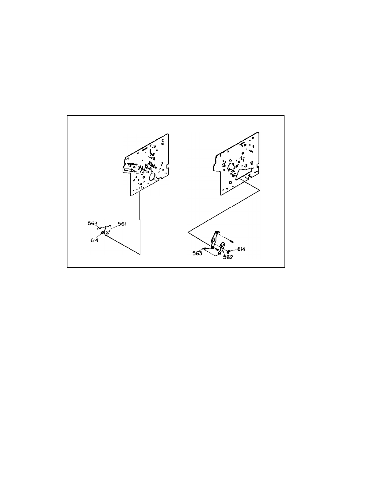
3. Resolution:
On each side of the CGS there is a friction clutch (Figure 1, Reference 561, 562, 563
and 614). These clutch plates must be removed, cleaned, lubricated and reinstalled.
This is the procedure:
1.
Remove the interlock switch before lifting the mechanism out.
2.
Remove the four screws that hold the mechanism in the printer, all cables and
ground straps.
3.
Remove the junction board, the PG sensor and the PG motor.
4.
Remove the E ring that holds the CGS gear and the other small gear.
5.
Remove the E ring (563) and spring (614) that attaches the “Guide shaft holding
lever” or clutch plate.
Page 2
PSB No: P-0102
Page: 2 of 2
6.
Clean the plate and the end of the CGS. Lube the assembly with light
machine oil (Epson 02 oil).
7.
Do the same for the right side by first removing the carrage motor.
Figure 1
8.
Remove the E ring and spring that attaches the “Guide shaft holding lever” or
clutch plate.
9.
Mark the parallelism adjustment plate and remove the two screws that attach it.
10. Clean the plates and the end of the CGS. Lube the assembly with light machine oil
11. Assemble in reverse order, do the PGM backlash adjustment, check and perform
the parallelism adjustment if necessary and test.
Page 3

EPSON AMERICA, INC.
Product Support Bulletin
Subject: DFX-5000, DFX-8000 and Avatar EP-Connect
EPSON
Date: 10/9/92
Page(s): 1 of 1
Avatar Corporation distributes the EP-Connect coax interface for the Epson DFXseries and other Epson dot-matrix printers that use A-type interfaces. This EPConnect coax interface allows a connection to an IBM 3174/3274/3276 control unit
or 4300 series Display Printer Adaptor using standard type A coaxial cable.
When using EP-Connect and the DFX-series printers, there have been some
intermittent operational problems reported. It has been determined that this is
caused by the type of connector used on the EP-Connect interface that plugs into
the printer’s main controller board. There are two types of connectors that have
been used on the EP-Connect coax interface. One type is a “FUJITSU” connector.
The other is a “HONDA” connector. The “FUJITSU” connector has slightly shorter
pins than the “HONDA’ connector. Epson America, Inc. does
use of the EP-Connect interface that has the ‘FUJITSU’ connector unless it is used
on a unit that has the countermeasure described below.
To identify which connector type the EP-Connect interface has, simply look directly
at the interface connector. The “HONDA” connector will have the name “HONDA
printed directly on the black part of the connector.
“FUJITSU” connector. Epson America, Inc. recommends the “HONDA” connector.
PSB No: P-0091
Originator: REW
not
recommend the
If there is no label, it is the
There are approximately 1,600 of the EP-Connect interfaces on the market that
contain the non-approved “FUJITSU” connector. To accommodate these interfaces
Epson has taken a countermeasure on the DFX series printers. This involves
adjusting the position of the ORII/F circuit board and changing the securing points.
As a result, Epson only recommends the use of the Avatar board with the
“FUJITSU” connector on DFX series printers that have the countermeasure
installed. The starting serial
installed is outlined below.
PRINTERS
DFX-5000
DFX-8000
If further information is needed on this subject, please contact Epson’s Technical
Support Department. For additional information on the EP-Connect interface,
please contact Avatar Corporation at (508) 435-6872.
number for the printers that have the countermeasure
STARTING SN#
0G20A11434
0VZ0007714
 Loading...