DIP-Switch Configurations: Provisions are made for DIP switch control for Off board circuitry characteristics
Self-Test Functions: Loopback and the line-monitor modes are for testing purposes
Connector: EIA standard 25 pin D-SUB female connector
Frequently Asked Questions
Q: What is the purpose of the C82307/C82308 Serial Interface Card?
A: This device is able to perform asynchronous serial data communication between an EPSON printer and a host computer.
Q: What types of handshaking protocols are supported?
A: The card supports X-on/X-off and DTR flag control protocols.
Q: What Baud Rates Can I Set the Interface on?
A: The term “baud rate”, which is the number of symbol changes per second, is in this case designating the range between 75 and 38 400 BPS, when using the signal levels RS-232D, RS-422A or Current Loop.
Q: Is it Possible to Alter the DIP Switch Settings After the Equipment Has Been Installed?
A: Yes. Only DIP switch 1 can be altered after installation while other switches and jumpers require the printer to be switched off first before any alterations can be made.
Q: What is Your Suggestion if I am Facing Interface Related Issues?
A: Automatically use al self-test functions onboard the card such as loopback mode or line-monitor mode to address the problem.
Q: Are Word Length and Parity Settings Available for Configuration?
A: Moreover, word length can be adjusted to 8 or 7 while parity can be set to a range of any configuration s odd, even none or ignore.
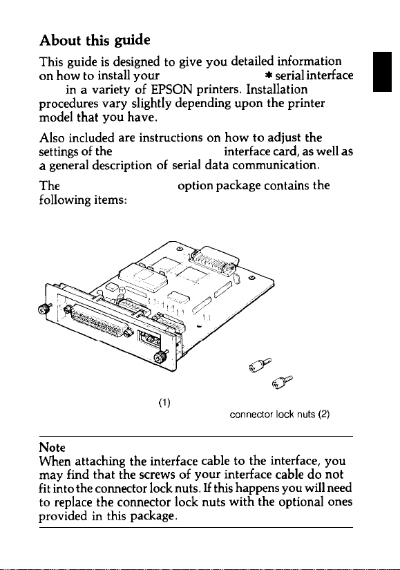
User Manual
Page 1
EPSON
32KB
Serial
Interface Card
C82307 *
C823088 *
English
Deutsch
Français
Español
Italiano
4000273
C01-00
Page 2
FCC
COMPLIANCESTATEMENT
FOR
Thisequipment hasbeentested andfound tocomply with thelimits for a Class B digital
AMERICAN
device,pursuant toPart 15 oftheFCCRules.These limits aredesigned toprovide
reasonable protection against harmful interference in a residential installation. This
equipment generates, uses,andcan radiate radiofrequency energy and, if notinstalled
andusedin accordance withthe instructions, maycauseharmful interference toradio
communications However. there is noguarantee that interference willnotoccurina
particular installation. If this equipment does cause harmful interference to radio or
television reception, which canbedetermined by turning theequipment off andon, the
useris encouraged totrytocorrecttheinterference byoneormore ofthefollowing
measures:
—
Reorient orrelocatethereceiving antenna
—
Increase the separation between theequipment and receiver.
—
Connect theequipment intoanoutleton a circuit different from that towhich the
receiveris connected.
This device complies withPart 15 oftheFCCRules.Operation is subject tothe following
twoconditions:
(1)
thisdevicemaynot causeharmful interference, and
(2)
this devicemust acceptanyinterference received,
including interference that may cause undesired operation.
Thisdigitalapparatus doesnotexceedtheClassB limits forradionoise emissions from
digital
apparatus assetoutintheradio interference regulations ofthe Canadian
Department of Communications
Le présent appareil numérique n´émet
applicables aux appareils numériques
brouillage radioélectrique édicté
The connection ofanon-shielded printer interface cabletothisprinter will invalidate
theFCCCertification ofthis device and may cause interference levelswhich exceed the
limits established bytheFCCfor this equipment If thisequipment hasmorethan one
SeikoEpsonCorporation shall notbeliableagainst anydamages or problems arising
fromtheuseofanyoptions or anyconsumable products other than those designated
asOriginal EpsonProducts orEpson Approved Products bySeikoEpson Corporation
All rights reserved. Reproduction ofanypart ofthismanual in anyformwhatsoever
without SeikoEpson’sexpress written permission is forbidden.
Thecontents ofthismanual aresubjecttochange without notice.
Allefforts have beenmadetoensuretheaccuracy ofthismanual. However, should any
errors bedetected, Seiko Epsonwould greatly appreciate being informed ofthem.
Theabove notwithstanding, Seiko Epsoncanassume no responsibility for anyerrors
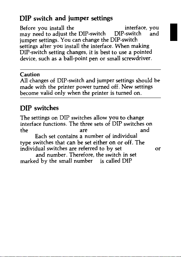
AllchangesofDIP-switch andjumper settings should be
madewiththe
becomevalid onlywhentheprinter is turned on.
after
youinstalltheinterface. Whenmaking
printer
power turned off.Newsettings
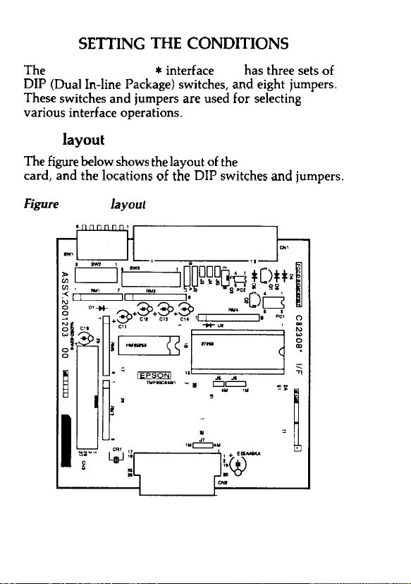
DIP switches
ThesettingsonDIPswitchesallowyoutochange
interface functions. ThethreesetsofDIPswitches on
the C82307* /C82308* are labelled SWl, SW2, and
Eachsetcontains anumber of individual toggle-
SW3.
typeswitches
individual switches arereferred tobyset (SW1, SW2, or
andnumber. Therefore, theswitchinset SW1
SW3)
marked by thesmallnumber 3 iscalledDIP switchl-3.
that
canbeseteither onoroff.The
5
Page 9
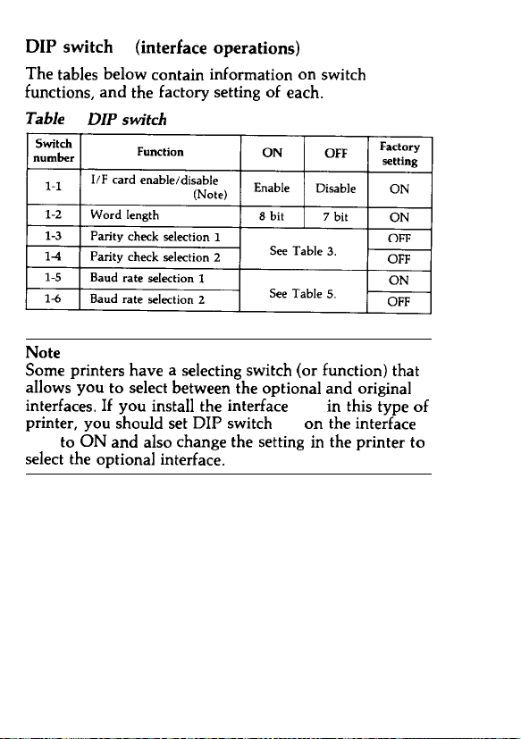
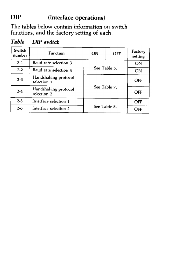
DIP switch
Thetables below contain information on switch
functions, andthe
Table 1. DIPswitch 1
Note
Some
allowsyoutoselectbetween theoptional andoriginal
interfaces. If youinstalltheinterface card inthistypeof
printer, you should setDIPswitch1-l ontheinterface
Duringthistest,data onthe RS-232D line, RS-422A
line,orCurrent-Loop lineisprinted in hexadecimal
code.Theonly difference between normal operation and
thismodeis
form.
that
mode
all
data is
converted intohexadecimal
22
Page 26
SPECIFICATIONS
1.
Synchronization: Asynchronous
2.
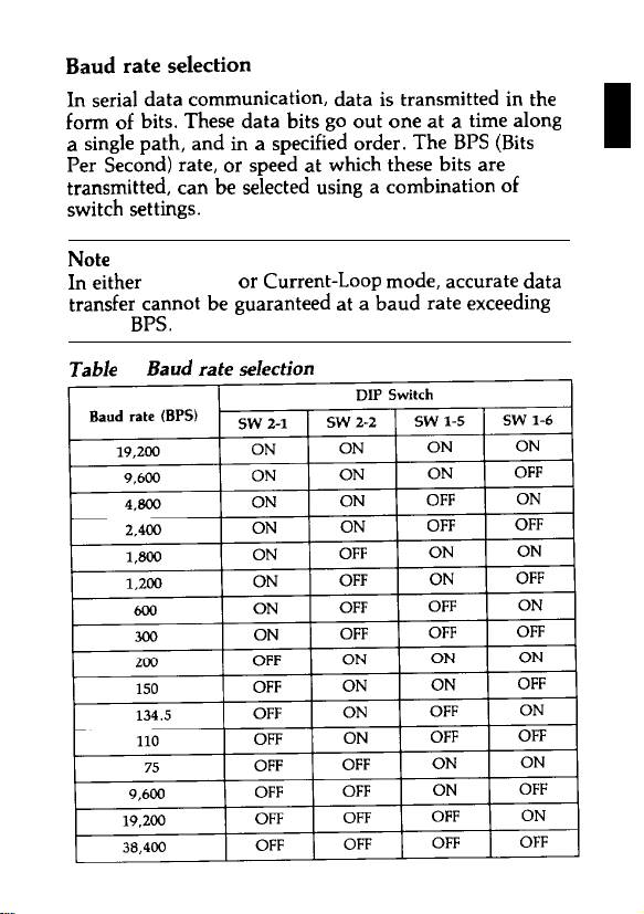
BaudRate: RS-232D: 75, 110, 134.5, 150, 200, 300,
3.
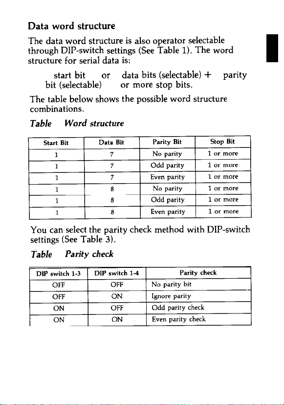
Wordlength:
Start bit: 1 bit
Data bit: 7 or 8 bits(selectable)
Parity bit:Odd,even,none,orignore(selectable)
Stopbit:
Inputsignalpolarity:
4.
1)
RS-232D:
MARK= logic "l" ( - 3 to - 25V)
SPACE= logic "0" ( + 3 to + 25V)
2)
RS-422A:
MARK = logic "1"
SPACE= logic "0"
3)
Current loop:
MARK = logic "1" (Current on)
SPACE= logic "0" (Current
600, 1,200, 1,800, 2,400, 4,800,
or 19,200
9,600,
RS-422A: 75, 110, 134.5, 150, 200, 300,
600, 1,200, 1,800, 2,400, 4,800,
9,600, 19,200,
(selectable)
Current Loop: 75, 110, 134.5, 150, 200,
300, 600, 1,200, 1,800, 2,400,
4,800, 9,600,
(selectable)
bitormore
1
The RDA is negative
withrespect tothe RDB.
The RDB is positive (+0.2 V to +6 V)
withrespect tothe RDB.


 Loading...