

Page 1

Control Pad and Touch Unit
Installation Guide
Guide d’installation de l’unité tactile
et du boîtier de commande
Page 2
About This Installation Guide
This guide describes how to install the Control Pad and Touch Unit (BrightLink® Pro 1430Wi) when using the
ELPMB28 wall mount with the BrightLink Pro 1420Wi/1430Wi ultra-short-throw projectors.
Safety Instructions
For your safety, read all the instructions in this guide before using the wall mount. Incorrect handling that
ignores instructions in this guide could damage the wall mount or could result in personal injury or property
damage. Keep this installation guide on hand for future reference.
Read the safety instructions in the online User's Guide for your projector and follow the instructions in this
document.
Explanation of Symbols
The warning marks shown below are used throughout this installation guide to prevent personal injury or
property damage. Make sure you understand these warnings when reading this installation guide.
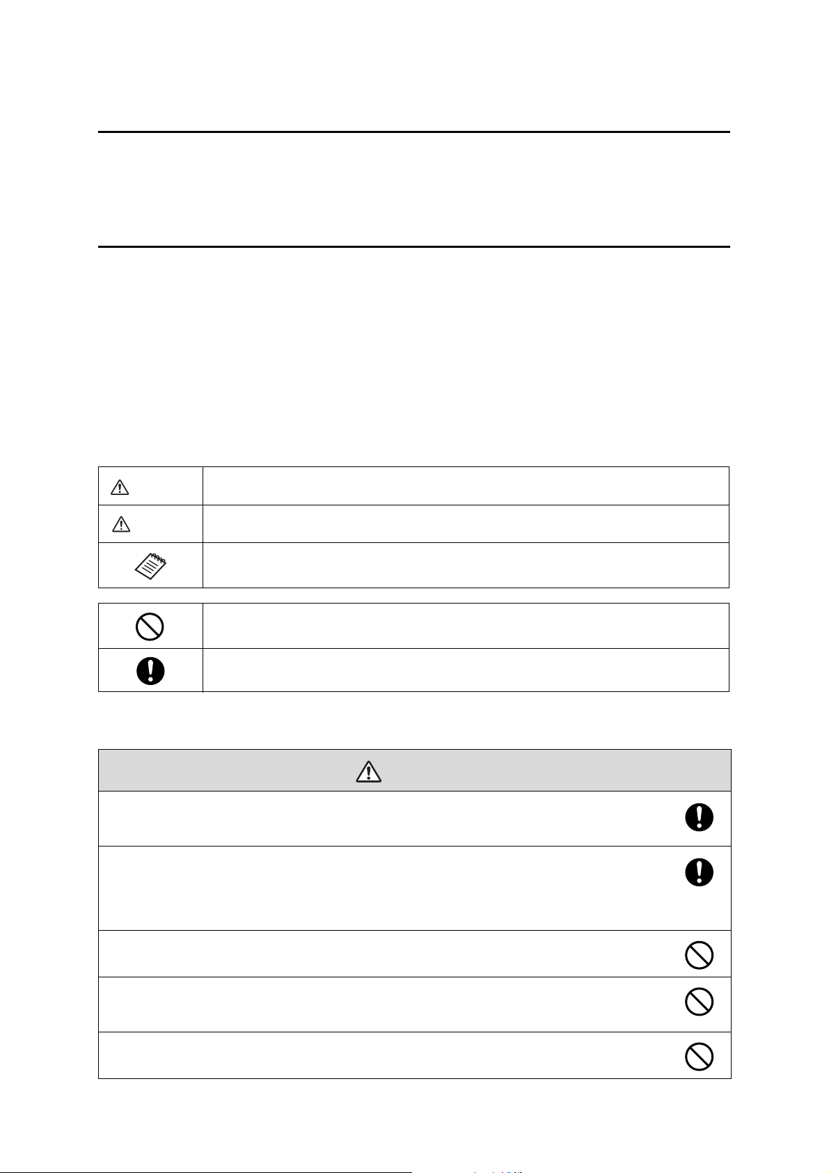
Warning
Caution
This symbol indicates information that, if ignored, could possibly result in personal injury or even death
due to incorrect handling.
This symbol indicates information that, if ignored, could possibly result in personal injury or physical
damage due to incorrect handling.
This symbol indicates related or useful information.
Symbol indicating an action that must not be done
Symbol indicating an action that should be done
Safety Precautions for Installation
Warning
Follow the instructions in this guide to install and operate the Touch Unit.
If the Touch Unit is not installed and operated properly, the light emitted from the laser could cause injury to
eyesight.
When you mount the projector on the wall with the wall mount, the wall must be strong enough to hold the
projector, the wall mount, as well as the Control Pad and the Touch Unit, if necessary.
The wall mount should be installed on a concrete wall. Confirm the weight of the projector, the wall mount,
the Control Pad, and the Touch Unit before installation, and maintain the strength of the wall. If the wall is
not strong enough, reinforce the wall before installation.
Never modify the wall mount, Control Pad, or Touch Unit.
Do not apply optical devices such as a magnifying glass or telescope to the laser light diffused from the
Tou ch Unit.
If such optical devices are applied, it could cause personal injury or fire.
Do not look into the Touch Unit’s laser diffusion ports.
This could cause injury to eyesight. Extra care should be taken when children are present.
2
Page 3
Warning
Do not view the laser light using optical devices such as a magnifying glass within a range of 2.75 in. (70
mm).
Viewing at close range could cause injury to eyesight.
Connect the Touch Unit to the BrightLink Pro 1430Wi model only. Do not connect it to any other projectors
or devices.
Do not use the Touch Unit if you are using or near medical equipment such as a pacemaker.
The magnet within the Touch Unit generates electromagnetic interference which could cause medical equipment
to malfunction.
Caution
Keep magnetic storage media (for example, magnetic cards or electronic devices such as computers,
digital watches, or cell phones) away from the Touch Unit.
The magnets within the Touch Unit generate electromagnetic interference which could corrupt data or cause the
media or device to malfunction.
Installation Location
• When powering the Control Pad using batteries, verify that the installation location meets the following
conditions:
• Install the Control Pad on the same surface as the projection screen. If the projection screen and the
Control Pad installation point are uneven, install the Control Pad approximately 8 in. (20 cm) from the
edge of the screen.
• Make sure there are no obstacles between the Control Pad and the projector (not including the Touch
Unit).
• Use the optional Remote Control Cable Set (model ELPKC28, part number V12H005C28) to supply power
to the Control Pad in the following situations:
• The required conditions above are not met.
• The projection screen and the Control Pad installation point are uneven and the difference in height is
more than 2 in. (5 cm).
• Multiple projectors are being used.
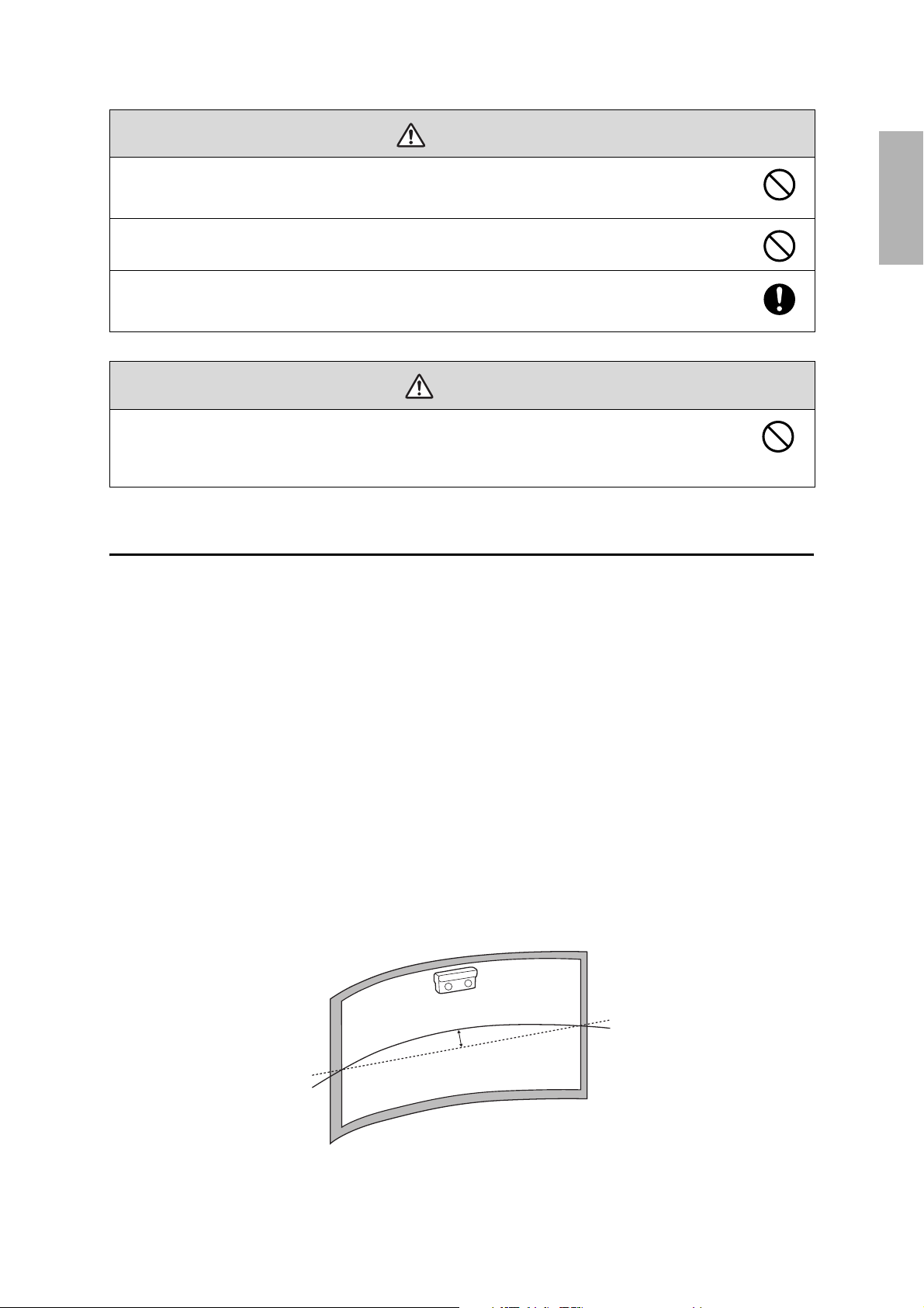
• Before installing the Touch Unit, verify that the installation location meets the following conditions:
• The Touch Unit can be secured to the surface with magnets or screws.
• The surface is flat, smooth, and unwarped with no more than 0.2 in. (5 mm) of unevenness in any
direction on the screen surface.
English
0.2 in. (5 mm)
3
Page 4
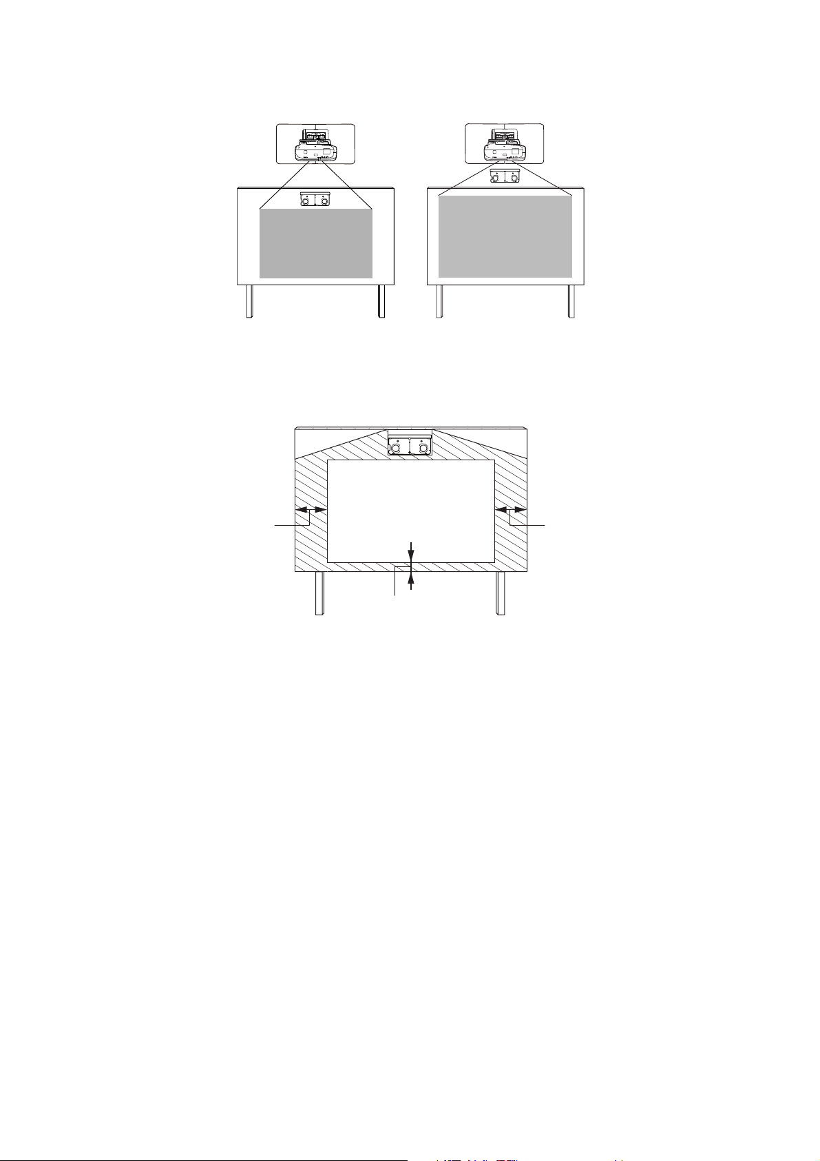
• When installing on a whiteboard, install the Touch Unit within the frame of the whiteboard.
Correct position Incorrect position
Make sure there are no obstacles, such as cables, or protruding objects such as whiteboard trays, pen
holders, or thick frames in the shaded areas in the following figure. The Touch Unit will not operate
correctly if anything is obstructing the infrared signal.
0.8 in. (20 mm)
4.0 in. (100 mm)4.0 in. (100 mm)
4
Page 5
1 Package Contents
s 6
2 Specifications
3 Connecting Devices
4 Installing the Touch Unit (BrightLink Pro 1430Wi)
1. Turn on the projectorTurn on the projector
2. Display the installation pattern
3. Remove the markers
4. Determine the installation position for the Touch Unit
5. Install the Touch Unit
6. Connect the cable
7. Adjust the angle
8. Store the markers and attach labels
9. Attach cover
5 Installing the Control Pad
1. Remove the cable cover
s 7
English
s 9
s 10
s 23
2. Attach the Control Pad
3. Install the batteries
4. Connect the projector cables to the Control Pad
5. Attach the port protection stickers
6. Attach the cable cover
6 Using the Easy Interactive Function
s 27
5
Page 6
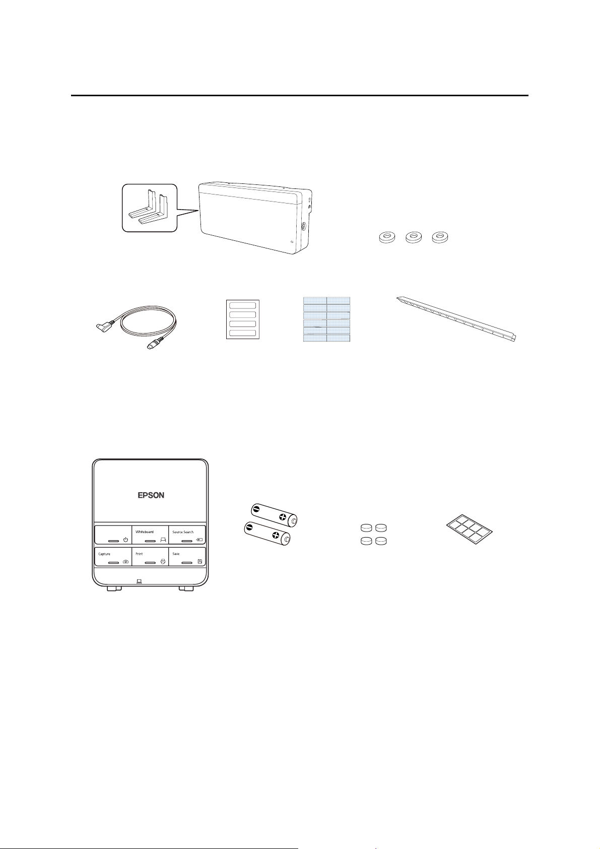
1 Package Contents
Touch Unit
The following parts are packaged with your projector and are necessary when attaching the Touch Unit. When
installing the Touch Unit on a non-magnetic surface, you will also need three M4 screws.
Touc h Unit a nd mar kers
(markers are inside the unit)
Touch Unit connection cable
Label (×4)
Tape (approx. 2.4 in [6
cm]) for securing the
markers (×12)
Spacer for screw hole (×3)
Infrared deflector (approx.
11.2 in [28.5 cm]) (×8)
Control Pad
The following parts are packaged with your projector and are necessary when attaching the Control Pad.
When installing the Control Pad on a wall, you will also need four M4 × 20 mm screws.
Control Pad
AA size batteries (× 2) Port protection
Rubber feet
stickers
6
Page 7
2Specifications
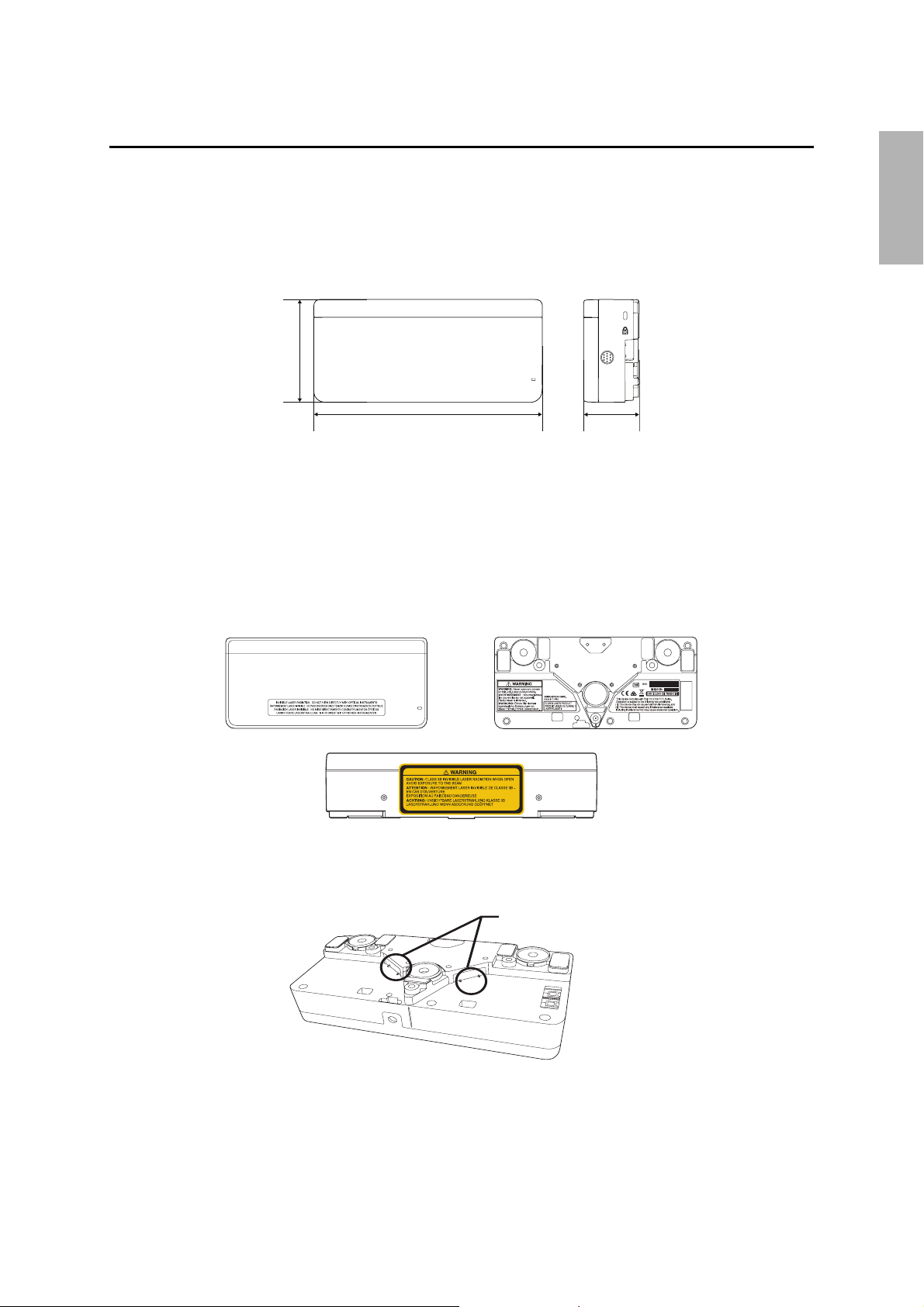
Touch Unit
External dimensions and weight
The Touch Unit weighs approximately 16 oz (450 g).
3.7 in. (95 mm)
English
8.3 in. (210 mm)
2.0 in.
(51 mm)
Attached labels
The Touch Unit is a Class 1 laser product that conforms to the JIS C 6802:2011 standard. There are warning
labels affixed to the Touch Unit to indicate that it is a Class 1 laser product. The labels contain the following
information:
• Invisible laser radiation
• Do not view the beam directly with optical instruments
• Class 1 laser product
Laser diffusion port
The laser beam is diffused from the laser diffusion ports on the back of the Touch Unit.
Laser diffusion ports
7
Page 8
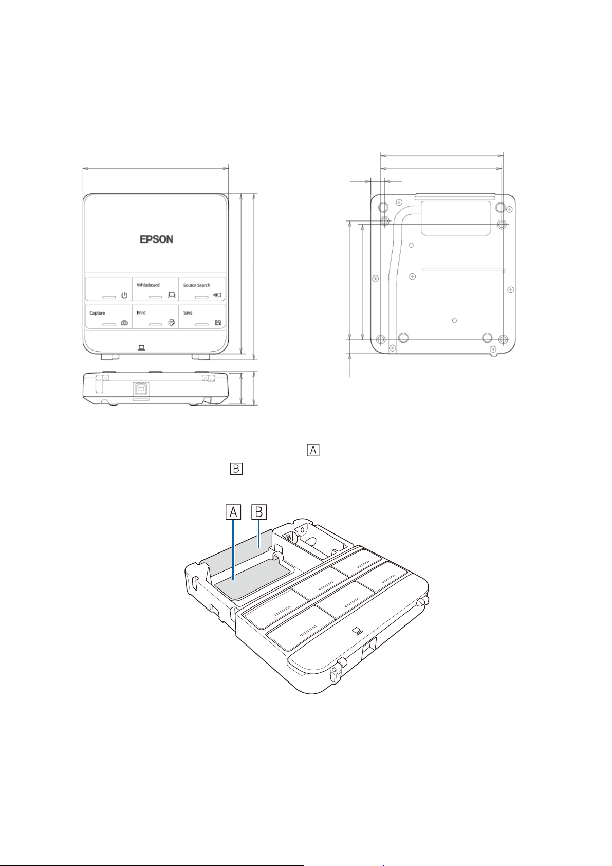
Control Pad
External dimensions and weight
The Control Pad weighs approximately 8.5 oz (240 g).
5.4 in. (135.9 mm)
5.9 in. (149 mm)
6.0 in. (153.5 mm)
1.2 in
1.1 in
(29 mm)
(30.9 mm)
0.4 in
(11.5 mm)
4.2 in. (107 mm)
0,6 in
(15.47 mm)
4.4 in. (111 mm)
4.3 in. (109 mm)
0.1 in. (3.5 mm)
4.0 in. (104 mm)
Cable routing holes
When routing cables through a wall, use the position ( ) in the following figure as the cable routing hole.
Otherwise, remove the cable cover ( ) and route the cables through the opening. Route the printer cable
along the groove on the back of the Control Pad.
8
Page 9
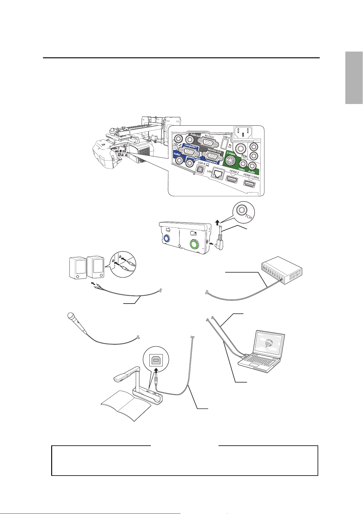
3Connecting Devices
Make sure you have the power cord, computer cable, and other parts at the location where the wall mount is
to be installed.
Make sure you also have all necessary cables for the Touch Unit and other devices, such as a document camera
or microphone, that you will connect to the projector. Your projector’s connection panel may differ slightly
from the displayed model. For details, refer to the online User’s Guide for your projector.
Touch Unit connection
Connection Example
External speakers
Tou ch Unit
cable
LAN device
English
Audio cable
(not included)
Microphone
Document camera
(Epson DC-06)
LAN cable
(not included)
Computer cable
(for computer video
output)
Computer
USB cable (for Easy
Interactive Function)
Dedicated USB cable
(supplied with document camera)
For Interactive Use
When interacting with a computer, you need a USB cable. However, when using the projector's
built-in toolbar, you do not need a USB cable.
9
Page 10
4 Installing the Touch Unit (BrightLink Pro 1430Wi)
The following procedures must be completed before installing the Touch Unit:
• Installing the projector (see the ELPMB28 Installation Guide)
• Adjusting the projected image (see the ELPMB28 Installation Guide)
• Calibrating the interactive pen(s)
s Refer to your projector User's Guide or Start Here folder for detailed instructions.
❏ There are magnets built in to the back of the Touch Unit. Typically, the Touch Unit
should be installed by attaching the magnets to the screen or whiteboard.
❏ If the magnets cannot be attached, use commercially available M4 screws (×3).
❏ Install the Touch Unit on a flat, smooth, unwarped surface that is the same level
surface as the screen surface. If there is unevenness on the screen surface of more
than 0.2 in. (5 mm) in any direction, your fingers may not be detected and finger
touch operations may not be performed correctly.
Follow the steps below to install the Touch Unit and connect to the projector. Some menus may differ slightly
from the illustrations, but the installation instructions are the same.
Caution
The Touch Unit should only be connected to the BrightLink Pro 1430Wi. Do not connect the
Touch Unit to any other projectors or devices.
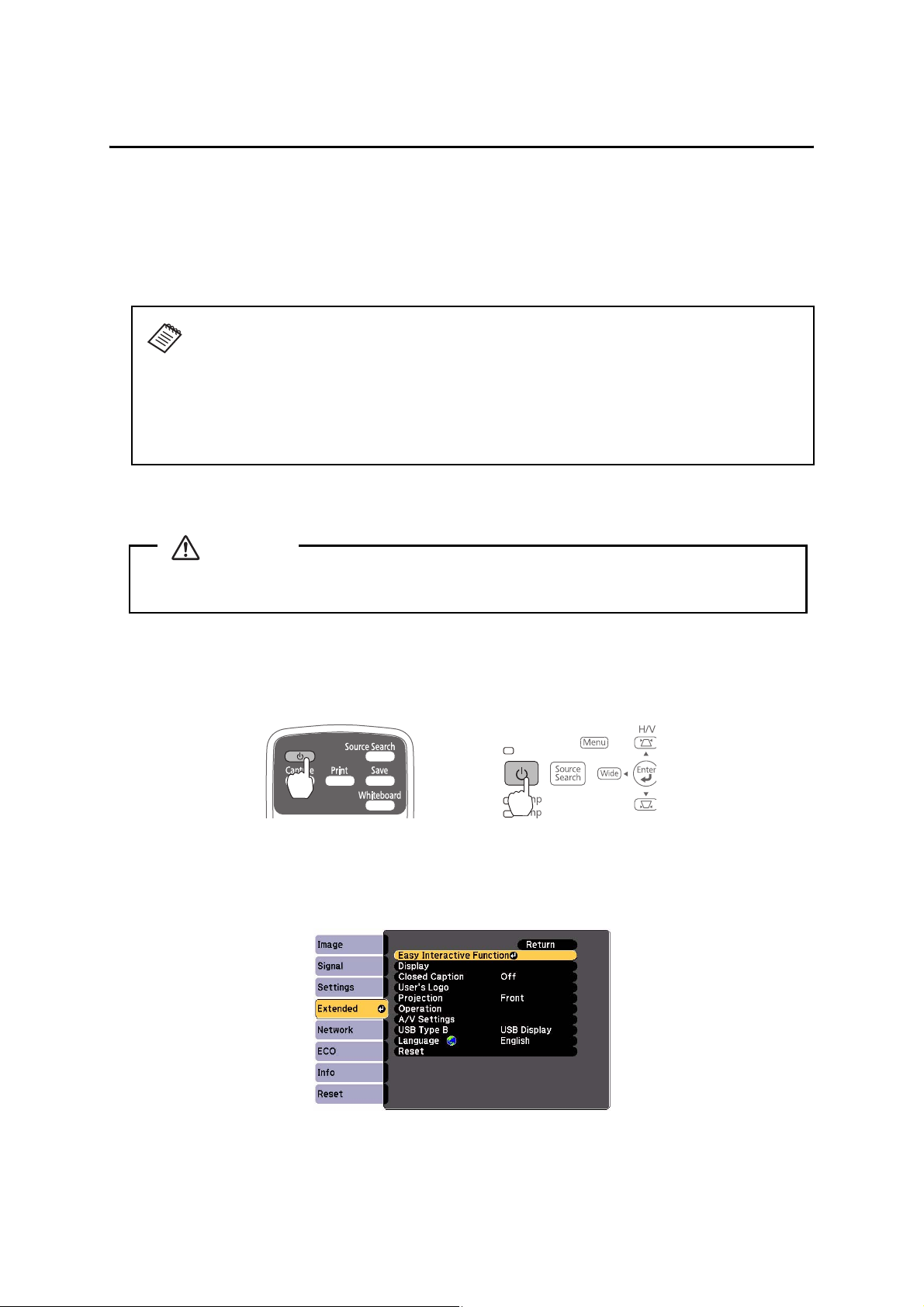
A Turn on the projector
Using the Remote Control Using the Control Panel
B Display the installation pattern
1. Select Easy Interactive Function from the Extended menu.
10
Page 11
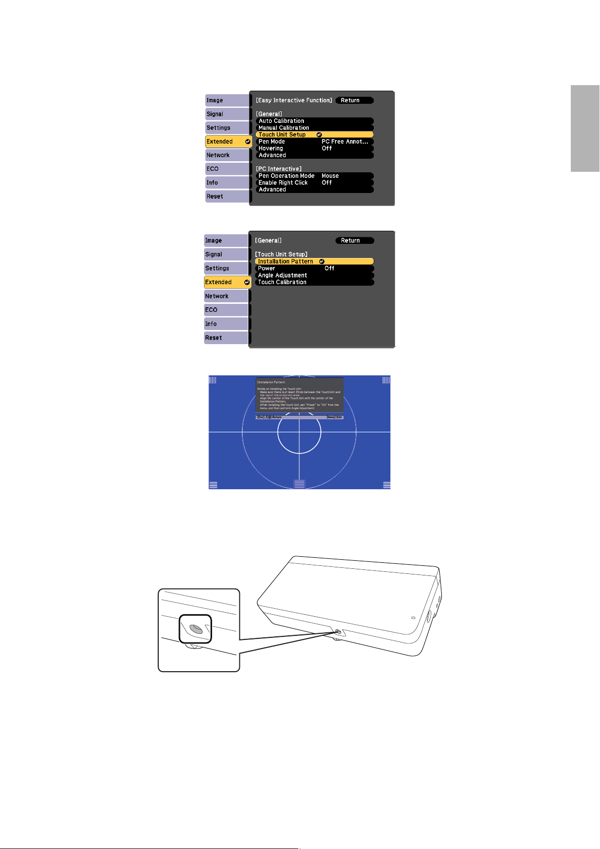
2. Select Touch Unit Setup.
3. Select Installation Pattern.
The Installation pattern is displayed on the projected image.
English
C Remove the markers
1. Loosen the screw at the bottom of the dial cover.
11
Page 12
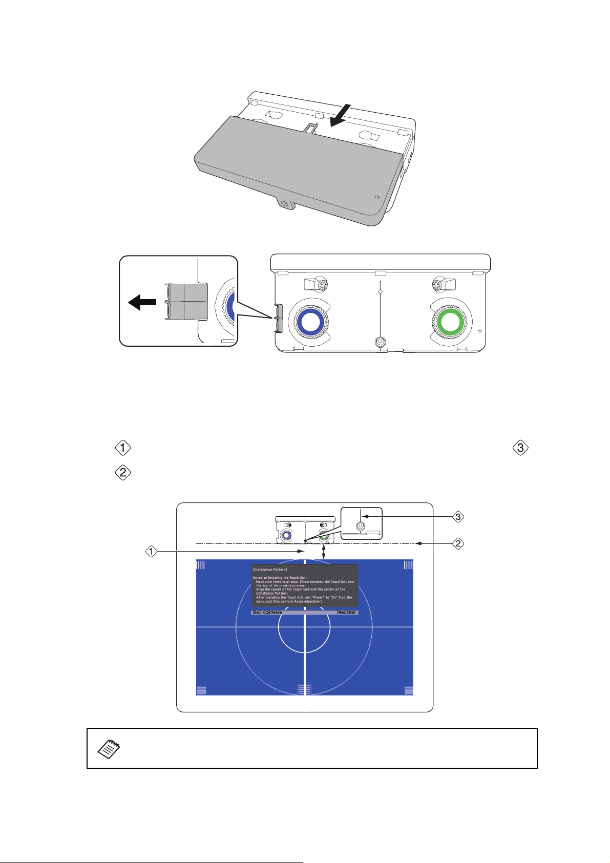
2. Slide the dial cover down to remove it.
3. Remove the two markers from inside the Touch Unit.
Use the markers to perform the angle adjustment (p. 14) after installing the Touch Unit.
D Determine the installation position for the Touch Unit
Mark the following installation positions:
• ( ): The center line of the installation pattern; align it with the center line of the Touch Unit ( ).
• ( ): 1 inch (25 mm) from the top edge of the projected image; align with the bottom edge of the
Touc h Unit.
1.0 in. (25 mm)
The Touch Unit must be installed above the image area.
12
Page 13
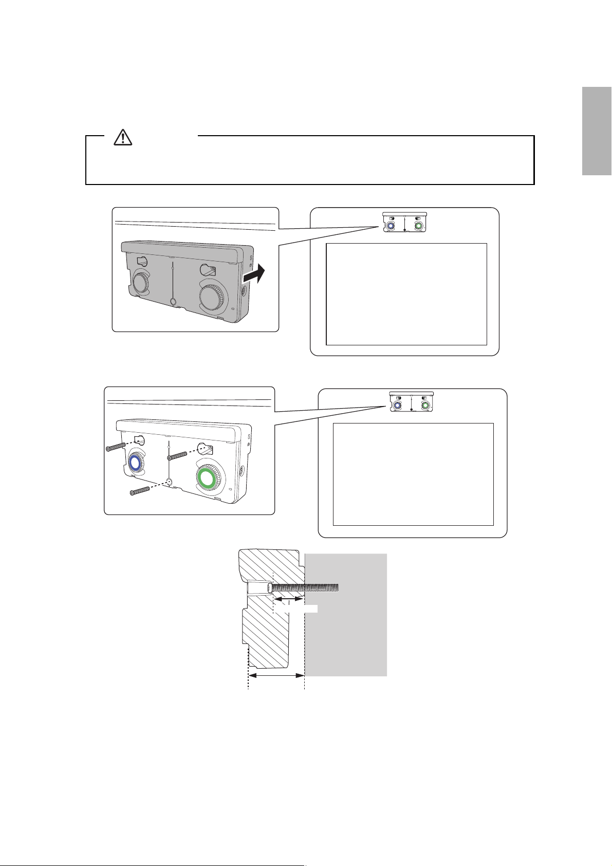
E Install the Touch Unit
• For magnetic screens, place the back of the Touch Unit on the screen surface to secure it.
Caution
When installing the Touch Unit on a magnetic surface, be careful not to trap your fingers or any
other part of your body between the magnets and the installation surface.
• For non-magnetic screens, secure the Touch Unit with three (3) M4 screws (not included).
English
0.8 in. (20 mm)
1.7 in. (43 mm)
13
Page 14
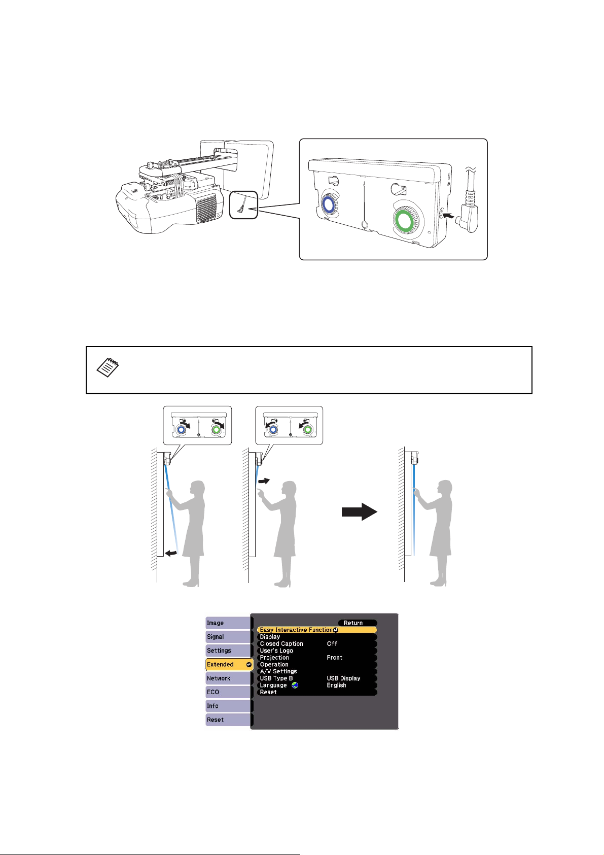
F Connect the cable
Connect the Touch Unit connection cable that is connected to the projector to the port on the Touch
Unit.
G Adjust the angle
Adjust the angle of the laser light coming from the Touch Unit so that the Touch Unit can detect the
position of your fingers.
Make sure to calibrate the interactive pen(s) before adjusting the angle. Press the User
button on the remote control and select Yes to perform an auto-calibration. Refer to
the projector’s online User’s Guide for detailed instructions on calibrating the pen(s).
1. Select Easy Interactive Function from the Extended menu.
14
Page 15
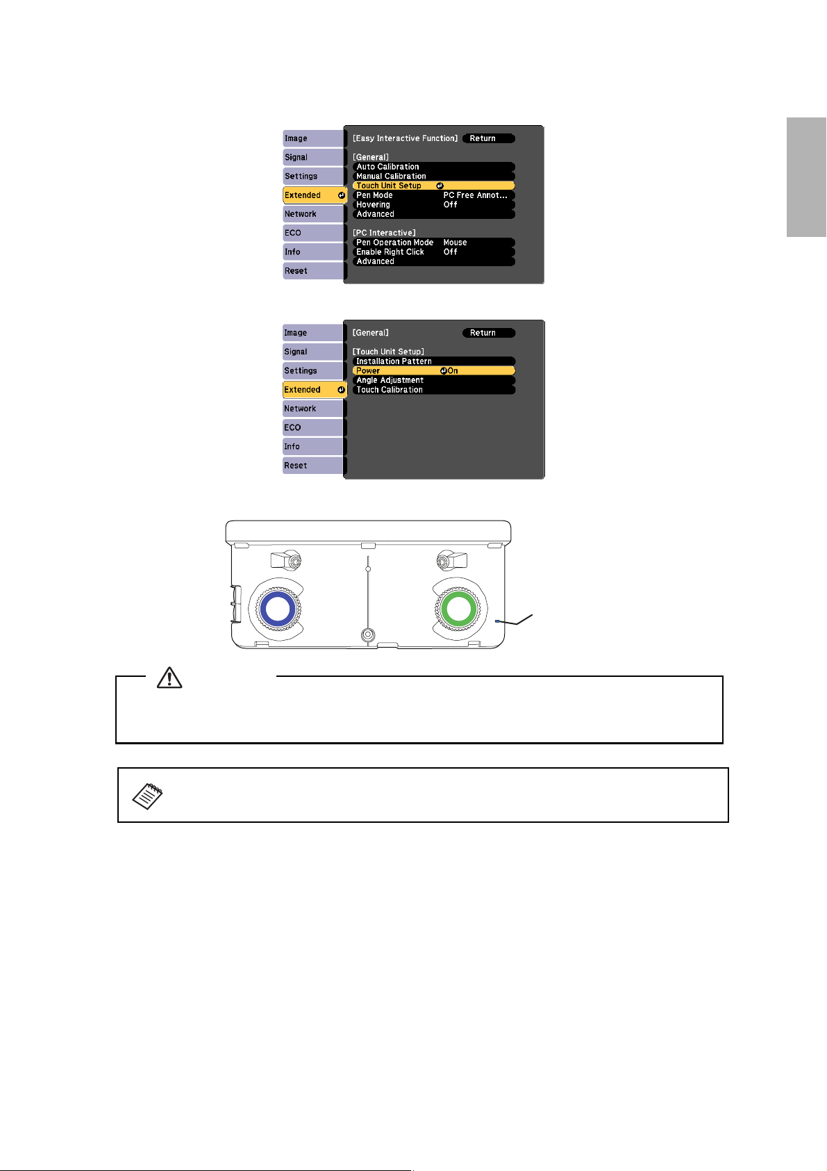
2. Select Touch Unit Setup.
3. Select Power and set to On.
The Touch Unit power turns on and the indicator light turns blue.
English
Indicator light
Warning
Do not look into the projector’s projection window or the Touch Unit’s laser diffusion ports
(located on the back of the Touch Unit); this could cause injury to eyesight.
When Power is set to On, the Touch Unit automatically powers up the next time the
projector is turned on.
15
Page 16
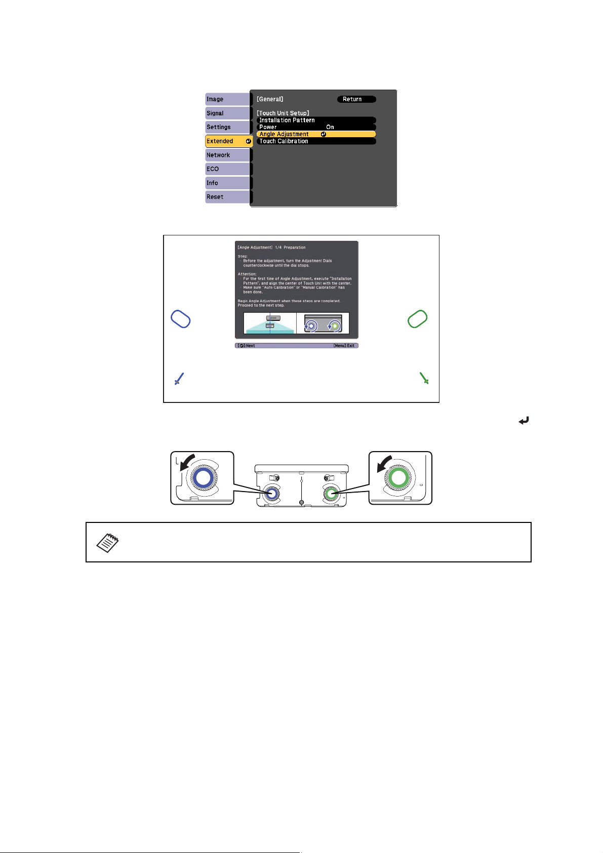
4. Select Angle Adjustment.
The Angle Adjustment screen is displayed.
5. Turn the adjustment dials on the Touch Unit counterclockwise until you hear a click. Then, press the
button on the remote control.
When adjusting the dials, make sure to stop turning when you hear the click.
16
Page 17
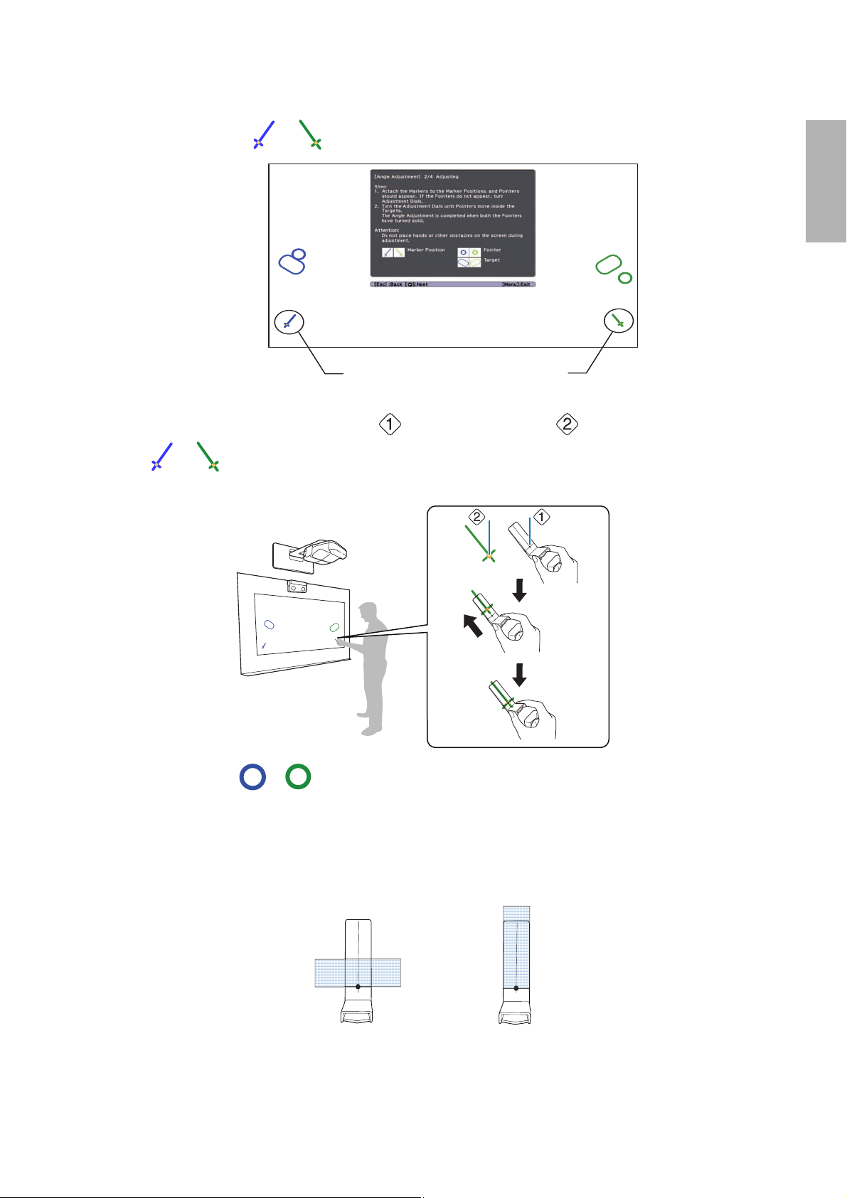
6. Attach the two markers you removed from the Touch Unit to the marker positions shown on the
projected screen ( ) ( ).
English
Blue marker
position
Match the positions so that the crosses ( ) overlap with the points ( ) on the marker positions
( ) ( ). Move the marker over the projected cross until the lines of the cross align with the lines
on the marker.
When pointers ( ) ( )
displayed on the left and right of the projection screen, attach the markers to the projection screen as
follows:
with the same color (blue and green) as the marker positions are
Green marker
position
• For magnetic screens: Place the bottom of the markers onto the screen.
• For non-magnetic screens: Use the supplied tape to secure the markers. Attach the tape so that each
end of the marker is secure on the screen.
Correct position Incorrect position
17
Page 18

Do not place anything other than the markers near the projected image during angle
adjustment. If other objects are on the projected image, angle adjustment may not be
performed correctly.
7. Turn the adjustment dials on the Touch Unit to move the pointers ( ) ( ) so that they move
inside of the target ( ) ( )
Turning an adjustment dial clockwise moves the pointer diagonally up towards the center of the
projected image.
Turning an adjustment dial counterclockwise moves the pointer diagonally down away from the center
of the projected image.
of the same color (blue and green) on either side.
When the pointers are inside the target, the colors become solid ( ) ( ).
❏ If a dial makes a clicking sound, the pointer will not move any further.
❏ When turning the dials, make sure shadows from your arm and body do not cover
the markers.
18
Page 19

8. When the pointers on the left and right become solid colors ( ) ( ), press the button on the
remote control. The following screen is displayed:
9. Place the markers at the top marker positions [1]. When angle adjustment is performed correctly, the
upper pointers become solid colors ( ) ( ). If the upper pointers do not become solid colors
( ) ( ), start again from step 4.
English
10. Place the markers at the bottom marker positions [2]. When angle adjustment is performed correctly,
the bottom pointers become solid colors ( ) ( ). If the bottom pointers do not become solid
colors ( ) ( ), start again from step 4.
19
Page 20

11. When you have finished checking the marker positions, remove the markers and press the button
on the remote control. The following confirmation screen is displayed:
12. Trace the dots with your finger as shown. When angle adjustment is performed correctly, the traced
dots disappear.
Finger touch operations may not function correctly if you are wearing bandages,
artificial nails, nail polish, or anything else that may obstruct your fingers.
20
Page 21

When all of the dots have disappeared, press the button on the remote control and then go to
step 13.
If any dots remain (as shown below), do the following:
• Remove any obstacles from around the projected screen. When you are finished, press the or
button on the remote control and repeat step 12.
• If the dots still remain after removing obstacles, turn the adjustment dials about a quarter turn
counterclockwise. Next, press the or button on the remote control and repeat step 12.
• If the dots still remain or there are obstacles that cannot be removed, such as whiteboard trays or
frames, go to step 13.
English
13. If there is an obstacle that cannot be removed, such as a whiteboard tray or frame, remove the tape
from the back of the supplied infrared deflectors and stick them to the screen so that the laser is not
reflected by the obstacle.
Make sure to stick the deflectors between the dots and the obstacle and adjust the number of
deflectors according to the number of dots.
❏ Do not remove an infrared deflector once it has been stuck in place.
❏ Do not stick tape or place anything on the infrared deflectors. The deflectors will
not function properly if anything is placed on them.
After placing the infrared deflectors, press the or button on the remote control, and then
repeat step 12.
If the dots do not disappear even after attaching the infrared deflectors, turn the adjustment dials
about a quarter turn counterclockwise. Next, press the or button on the remote control,
and then repeat step 12 again.
If the dots do not disappear even after performing the above procedures, contact Epson.
21
Page 22

14. Perform touch calibration by pressing Menu on the remote control. On the Extended menu, select
Easy Interactive Function, then Touch Unit Setup. Select Touch Calibration and follow the
instructions.
H Store the markers and attach labels
1. Store the markers inside the Touch Unit.
2. Attach the labels to the tabs on either side of the Touch Unit. Match the centers of the labels with the
tabs on the Touch Unit.
If the Touch Unit moves out of position, use the position of the labels to determine
where to reposition the Touch Unit.
I Attach cover
Attach the dial cover. Make sure to tighten the screw at the bottom of the cover.
22
Page 23

5 Installing the Control Pad
You must install the control pad on the same surface as the projector, within the range specified in the
installation instructions. You can use batteries to power the control pad, or the optional remote control cable
set (model ELPKC28, part number V12H005C28).
You must have completed the steps in “Installing the Projector” in the Installation Guide before installing the
Control Pad.
Follow the steps below to install the Control Pad and connect to the projector.
Caution
The Control Pad should only be connected to the BrightLink Pro 1420Wi/1430Wi. Do not
connect the Control Pad to any other projectors.
Check the installation location
The Control Pad must be installed in the area specified in the diagram below.
13.8 in.
78.7 in.
(2.0 m)
68.9 in.
(1.75 m)
35.4 in.
(0.9 m)
27.6 in.
(0.7 m)
(0.35 m)
9.8 in.
(0.25 m)
60-inch
image
Remote control
light emitting areas
English
100-inch
image
39.3 in. (1.0 m)
59.0 in. (1.5 m)
78.7 in. (2.0 m)
Make sure there is enough space surrounding the Control Pad. Because the top panel
opens from the left, there must be additional space to the left of the Control Pad.
2 in. (50 mm)
3.9 in
(100 mm)
2 in. (50 mm)
2 in
(50 mm)
23
Page 24

A Remove the cable cover
B Attach the Control Pad
Attach the Control Pad with commercially available M4 × 20 mm screws (×4).
Warning
❏ Make sure the screws are not angled.
❏ Make sure the Control Pad is firmly attached.
❏ Do not attach the Control Pad with double-side tape or magnets.
❏ Check that the Control Pad is operating correctly before attaching it with the
screws.
❏ When installing the Control Pad on a table, attach the supplied rubber feet (x4) to
the base of the Control Pad to prevent it from slipping.
24
Page 25

C Install the batteries
Caution
Before handling the batteries, read the safety instructions in your projector’s online
User’s Guide.
English
❏ Use two AA manganese or alkaline (recommended) batteries. Do not use any other
type of battery. Rechargable batteries cannot be used.
❏ In order to use the projector to power the Control Pad, connect the optional
Remote control cable set (model ELPKC28, part number V12H005C28) to the
projector’s Remote port and the Control Pad’s Remote port. Do not install
batteries.
D Connect the projector cables to the Control Pad
USB cable 1
Remote control cable
USB cable 2
USB cable 3
USB cable 4
25
USB flash drive
Page 26

To perform the functions listed below, you will need to connect the appropriate cables:
Projector function Required cables
Projecting images from a USB flash drive USB cable 1
Saving data to a USB flash drive
Supplying power from the projector Remote control cable set
(model ELPKC28; part number
V12H005C28)
Projecting computer images with USB Display or
performing mouse functions using the Easy
Interactive Function
Printing a projected image USB cable 1
E Attach the port protection stickers
Cover the Control Pad ports that are not being used.
F Attach the cable cover
USB cable 2
USB cable 3
USB cable 4
26
Page 27

6 Using the Easy Interactive Function
After you install your BrightLink model (and the Touch Unit, if applicable), you need to perform calibration to
align the positions of the cursor and your interactive pen(s) (and finger, if the Touch Unit is installed). See the
projector’s online User’s Guide or Start Here folder for detailed instructions.
In order to use the Easy Interactive Tools software, you must first install the software on the computer. OS X
users also need to install a driver that enables pen or finger touch interactivity to work. Both software
programs are included with the BrightLink projector.
For details, see the online User's Guide or visit:
U.S.: epson.com/support/brightlinkdownloads
Canada: epson.ca/support/brightlinkdownloads
English
27
Page 28

28
Page 29

À propos de ce guide d’installation
Ce guide décrit comment installer l’unité tactile et le boîtier de commande (BrightLink® Pro 1430Wi) lorsque
vous utilisez le support de montage mural ELPMB28 avec les projecteurs à ultra-courte distance de projection
BrightLink Pro 1420Wi/1430Wi.
Consignes de sécurité
Pour votre sécurité, veuillez lire toutes les consignes contenues dans ce guide avant d’utiliser le support de
montage mural. Une manipulation incorrecte ne respectant pas ces consignes pourrait endommager le
support de montage ou provoquer des blessures corporelles ou des dommages matériels. Conservez ce guide
d’installation à portée de main pour pouvoir vous y reporter ultérieurement.
Lisez les consignes de sécurité dans le Guide de l’utilisateur en ligne de votre projecteur et suivez les
instructions figurant dans ce document.
Explication des symboles
Les symboles d’avertissement ci-dessous sont utilisés dans ce guide d’installation afin de vous éviter de vous
blesser ou de provoquer des dommages matériels. Assurez-vous de bien avoir compris la signification de ces
avertissements lorsque vous lisez ce guide.
Français
Avertissement
Mise en garde
Ce symbole signale des informations qui, si elles sont ignorées, peuvent provoquer des blessures, voire la
mort, en raison d’une manipulation incorrecte.
Ce symbole indique des informations qui, si elles sont ignorées, peuvent provoquer des blessures ou des
dommages physiques, en raison d’une manipulation incorrecte.
Ce symbole signale des informations connexes ou utiles.
Symbole indiquant une action à ne pas faire
Symbole indiquant une action à faire
Consignes de sécurité pour l’installation
Avertissement
Suivez les instructions du présent guide pour installer et utiliser l’unité tactile.
Si l’unité tactile n’est pas installée et utilisée de façon appropriée, la lumière émise par le laser pourrait entraîner
des lésions oculaires.
La fixation du projecteur sur un mur à l’aide du support de montage doit être effectuée sur un mur
suffisamment solide pour maintenir le projecteur, le support de montage, ainsi que le boîtier de
commande et l’unité tactile, au besoin.
Ce support de montage doit être installé sur un mur en béton. Vérifiez donc le poids du projecteur, du
support de montage, du boîtier de commande et de l’unité tactile avant l’installation et veillez à la bonne
solidité du mur. Si la solidité du mur est insuffisante, renforcez le mur avant de procéder à l’installation.
Ne modifiez jamais le support de montage, le boîtier de commande ou l’unité tactile.
29
Page 30

Avertissement
N’appliquez pas d’appareils optiques tels qu’une loupe ou un télescope à la lumière laser diffusée depuis
l’unité tactile.
L'utilisation d'appareils optiques dans ces conditions pourrait entraîner des blessures ou un incendie.
Ne regardez pas dans les ports de diffusion laser de l’unité tactile.
Cela pourrait entraîner des problèmes oculaires. Veuillez prêter une attention particulière lorsque des enfants sont
présents.
Ne regardez pas la lumière laser en utilisant des appareils optiques tels qu’une loupe à moins de 2,75 po
(70 mm).
Le visionnement à portée réduite peut entraîner des problèmes oculaires.
Connectez l’unité tactile au modèle BrightLink Pro 1430Wi seulement. Ne connectez pas l’unité à d’autres
projecteurs ou appareils.
N’utilisez pas l’unité tactile si vous utilisez ou êtes à proximité d’équipement médical tel qu’un stimulateur
cardiaque.
L’aimant de l’unité tactile génère de l’interférence électromagnétique qui pourrait entraîner une défaillance de
l’équipement médical.
Mise en garde
Conservez les appareils de stockage magnétiques (par exemple, les cartes magnétiques ou les appareils
électroniques tels que les ordinateurs, les montres à affichage numérique ou les téléphones cellulaires)
loin de l’unité tactile.
L’aimant à l’intérieur de l’unité tactile génère de l’interférence magnétique qui pourrait corrompre les données ou
entraîner un mauvais fonctionnement des appareils ou supports.
Emplacement pour l’installation
• Lorsque le boîtier de commande est alimenté par des piles, suivez les directives suivantes lors de
l’installation :
• Installez le boîtier de commande sur la même surface que l’écran de projection. Si l’écran de
projection et le point d’installation du boîtier de commande ne sont pas au même niveau, installez le
boîtier de commande à environ 20 cm (8 po) du bord de l’écran.
• Assurez-vous qu’il n’y a aucun objet bloquant le signal entre le boîtier de commande et le projecteur
(à l’exception de l’unité tactile).
• Utilisez l’ensemble de câbles de la télécommande optionnel (modèle ELPKC28, numéro de pièce
V12H005C28) pour alimenter le boîtier de commande lors des situations suivantes :
• Les directives mentionnées ci-dessus ne peuvent pas être suivies.
• L’écran de projection et le point d’installation du boîtier de commande ne sont pas au même niveau
et la différence de hauteur est de plus de 2 po (5 cm).
• Plusieurs projecteurs sont utilisés.
• Avant d’installer l’unité tactile, vérifiez si l’emplacement pour l’installation répond aux critères suivants :
• L’unité tactile peut être fixée à la surface avec des aimants ou des vis.
30
Page 31

• La surface est plate, lisse et régulière avec moins de 5 mm (0,2 po) d’inégalité (dans toutes les
directions) sur la surface de l’écran.
5 mm (0,2 po)
• Lors de l’installation sur un tableau blanc, installez l’unité tactile à l’intérieur du cadre du tableau
blanc.
Position correcte Position incorrecte
Français
• Assurez-vous qu’il n’y a pas d’obstacles, par exemple des câbles ou des objets protubérants comme des
plateaux pour tableau blanc ou des cadres épais dans les zones ombrées de l’illustration ci-dessous.
L’unité tactile ne fonctionnera pas correctement si le signal infrarouge est bloqué.
100 mm (4,0 po)100 mm (4,0 po)
20 mm (0,8 po)
31
Page 32

1 Contenu de l’emballage
s 33
2 Spécifications
3 Connexion des appareils
4 Installation de l’unité tactile pour les projecteurs
BrightLink Pro 1430Wi
1. Mettez le projecteur sous tension
2. Affichez le motif d’installation
3. Retirez les marqueurs
4. Déterminez la position d’installation de l’unité tactile
5. Installez l’unité tactile
6. Branchez le câble
7. Réglez l’angle
8. Stockez les marqueurs et posez les étiquettes
9. Posez le couvercle
5 Installation du boîtier de commande
s 34
s 35
s 38
s 51
1. Retirez le cache-câbles
2. Fixez le boîtier de commande
3. Installez les piles
4. Connectez les câbles du projecteur au boîtier de commande
5. Apposez les autocollants de protection de port
6. Fixez le cache-câbles
6 Pour la fonction Easy Interactive
s 55
32
Page 33

1 Contenu de l’emballage
Unité tactile
Les pièces suivantes sont emballées avec votre projecteur et sont nécessaires lors de l’installation de l’unité
tactile. Lorsque vous installez l’unité tactile sur une surface non magnétique, vous aurez aussi besoin de
vis M4.
Rondelle d’espacement pour trou de
Unité tactile et marqueurs
(les marqueurs sont à l’intérieur de l’unité)
Étiquettes (×4)
Câble de connexion
pour unité tactile
Ruban adhésif (approx.
6cm[2,4po]) pour fixer
les marqueurs ×12
vis (×3)
Déflecteurs infrarouges
(approx. 28,5 cm [11,2 po]) ×8
Boîtier de commande
Français
Les pièces suivantes sont emballées avec votre projecteur et elles sont requises pour fixer le boîtier de
commande. Lorsque vous installez le boîtier de commande sur un mur, vous aurez aussi besoin de quatre
vis M4 x 20 mm.
Piles de format AA (x 2) Autocollants de
Boîtier de commande
Pieds en
plastique
protection de port
33
Page 34

2Spécifications
Unité tactile
Dimensions externes et poids
L’unité tactile pèse environ 450 g (16 oz).
95 mm (3,7 po)
210 mm (8,3 po)
51 mm
(2,0 mm)
Étiquettes d’avertissement
L’unité tactile est un produit laser de classe 1 qui est conforme à la norme JIS C 6802:2011. Des étiquettes
d’avertissement sont apposées à l’unité tactile afin d’indiquer qu’il s’agit d’un produit laser de classe 1. Les
étiquettes contiennent les informations suivantes :
• Radiations laser invisibles
• Évitez de regarder le faisceau laser directement avec des instruments optiques
• Produit laser classe 1
34
Page 35

Port de diffusion du laser
Le faisceau laser est diffusé depuis les ports de diffusion laser à l’arrière de l’unité tactile.
Ports de diffusion laser
Boîtier de commande
Dimensions externes et poids
Le boîtier de commande pèse environ 240 g (8,5 oz).
111 mm (4,4 po)
135,9 mm (5,4 po)
11,5 mm
(0,4 po)
109 mm (4,3 po)
3,5 mm (0,1 po)
Français
149 mm (5,9 po)
153,5 mm (6,0 po)
107 mm (4,2 po)
104 mm (4,0 po)
(0,6 po)
15,47 mm
29 mm
(1,2 po)
(1,1 po)
30,9 mm
Trous pour le passage des câbles
Lorsque vous faites passer les câbles à travers un mur, utilisez la position ( ) dans l’illustration suivante
comme trou pour le passage des câbles.
35
Page 36

Sinon, retirez le cache-câbles ( ) et faites passer les câbles à travers l’ouverture. Faites passer le câble de
l’imprimante le long de la rainure à l’arrière du boîtier de commande
36
Page 37

3 Connexion des appareils
Assurez-vous d’avoir le cordon d’alimentation, le câble d’ordinateur et les autres pièces à l’emplacement
d’installation du support de montage.
Assurez-vous aussi d’avoir tous les câbles nécessaires pour l’unité tactile et tous les appareils que vous envisagez
de connecter au projecteur, par exemple, une caméra de documents ou un microphone. Il est possible que le
panneau de connexion soit différent de celui du modèle illustré. Pour obtenir plus de détails, consultez le Guide
de l’utilisateur en ligne pour votre projecteur.
Exemple de connexion
Haut-parleurs externes
Unité tactile
Câble de connexion
pour unité tactile
Appareil réseau local
Français
Câble réseau local
(non inclus)
Câble audio
Microphone
Caméra de
documents
(Epson DC-06)
(non inclus)
Câble USB dédié
(fourni avec la caméra de documents)
Câble d’ordinateur
(pour la sortie vidéo de
l’ordinateur)
Ordinateur
Câble USB (pour la
fonction Easy Interactive)
Pour la fonction interactive
Lorsque vous interagissez avec l’image projetée via une connexion à un ordinateur, un câble
USB est nécessaire. Vous n’avez cependant pas besoin d’un câble USB lorsque vous interagissez
avec l’image projetée à l’aide de la fonction intégrée du projecteur.
37
Page 38

4 Installation de l’unité tactile pour les projecteurs BrightLink Pro 1430Wi
Assurez-vous que les procédures suivantes ont bien été réalisées avant d’installer l’unité tactile.
• Installation du projecteur (voir Guide d’installation ELPMB28)
• Réglage de l’image projetée (voir Guide d’installation ELPMB28)
• Calibrage du ou des crayons interactifs
s Veuillez vous référer au Guide de l’utilisateur en ligne ou à l’affiche Point de départ pour obtenir
des instructions plus détaillées.
❏ Des aimants sont intégrés à l’arrière de l’unité tactile. Normalement, l’unité tactile
doit être installée en fixant les aimants à l’écran ou au tableau blanc.
❏ Si les aimants ne peuvent pas être fixés, utilisez des vis M4 (x3) disponibles dans le
commerce.
❏ Installez l’unité tactile sur une surface plate, lisse et régulière qui est au même
niveau que la surface de l’écran. Si des irrégularités de plus de 5 mm (0,2 po) sont
présentes sur la surface de l’écran (dans n’importe quelle direction), la position de
vos doigts pourrait ne pas être détectée et les opérations tactiles pourraient mal
fonctionner.
Suivez les étapes ci-dessous pour installer l’unité tactile et effectuer la connexion au projecteur. Il est possible
que l’apparence de certains menus soit différente des illustrations, mais les instructions d’installation
demeurent les mêmes.
Mise en garde
Ne branchez l’unité tactile qu’au modèle BrightLink Pro 1430Wi. Ne branchez pas l’unité tactile
à d’autres projecteurs ou appareils.
A Mettez le projecteur sous tension
Avec la télécommande Avec le panneau de commande
B Affichez le motif d’installation
1. Sélectionnez Easy Interactive Function depuis le menu Avancé.
38
Page 39

2. Sélectionnez Config. uni. tactile.
3. Sélectionnez Motif d’installation.
Le motif d’installation s’affiche sur l’image projetée.
Français
C Retirez les marqueurs
1. Desserrez la vis dans la partie inférieure du couvercle des cadrans.
39
Page 40

2. Faites glisser le couvercle des cadrans afin de le retirer.
3. Retirez les deux marqueurs de l’unité tactile.
Utilisez les marqueurs pour effectuer l’ajustement de l’angle (p. 42) après avoir installé l’unité tactile.
D Déterminez la position d’installation de l’unité tactile
Veuillez marquer les positions d’installation suivantes :
• ( ) : Ligne centrale du motif d’installation. Alignez-la avec la ligne centrale de l’unité tactile ( ).
• ( ) : 1 po (25 mm) depuis le bord supérieur de l’image projetée. Alignez avec le bord inférieur de
l’unité tactile
.
L’unité tactile doit être installée au-dessus de la zone d’image.
40
Page 41

E Installez l’unité tactile
• Pour les écrans magnétiques, placez l’arrière de l’unité tactile sur la surface de l’écran, puis fixez-la.
Mise en garde
Lors de l’installation de l’unité tactile sur une surface magnétique, veillez à ne pas coincer vos
doigts ou toute autre partie de votre corps entre les aimants et la surface d’installation.
• Pour les écrans non magnétiques, fixez bien l’unité tactile à l’aide de trois (3) vis M4 (non incluses).
Français
20 mm (0,8 po)
43 mm (1,7 po)
41
Page 42

F Branchez le câble
Branchez le câble de connexion de l'unité tactile au port de l'unité tactile. L'autre extrémité devrait déjà être
branchée au projecteur.
G Réglez l’angle
Réglez l’angle du faisceau laser émis par l’unité tactile afin que l’unité tactile puisse détecter la position de vos
doigts.
Avant d’ajuster l’angle, assurez-vous que le calibrage du ou des crayons interactifs est
terminé. Appuyez sur le bouton User de la télécommande et sélectionnez Oui afin
d’effectuer un calibrage automatique. Veuillez consulter le Guide de l’utilisateur en
ligne pour obtenir des instructions détaillées sur le calibrage des crayons.
1. Sélectionnez Easy Interactive Function depuis le menu Avancé.
42
Page 43

2. Sélectionnez Config. uni. tactile.
3. Sélectionnez Alimentation et réglez le paramètre à On.
L’unité tactile s’allume et le témoin indicateur s’allume en bleu.
Français
Témoin indicateur
Avertissement
Ne regardez pas la fenêtre de projection du projecteur ou les ports de diffusion laser de l’unité
tactile. Ceci pourrait entraîner des problèmes oculaires.
Lorsque le paramètre Alimentation est réglé à On, l’unité tactile s’allumera
automatiquement au prochain démarrage du projecteur.
43
Page 44

4. Sélectionnez Réglage de l’angle.
L’écran de réglage de l’angle s’affiche.
5. Tournez les cadrans de réglage de l’unité tactile dans le sens inverse des aiguilles d’une montre jusqu’à
ce que vous entendiez un clic. Puis, appuyez sur le bouton de la télécommande.
Lorsque vous ajustez les cadrans, assurez-vous de cesser de tourner lorsque vous
entendez un clic.
44
Page 45

6. Placez les deux marqueurs que vous avez retirés de l’unité tactile sur les positions des marqueurs
( ) ( ) sur l’écran de projection.
Français
Position du
marqueur bleu
Faites correspondre les positions de sorte que les croix ( ) soient superposées avec les points ( )
sur les positions des marqueurs ( ) ( ) . Déplacez le marqueur sur la croix projetée jusqu’à ce
les lignes de la croix soient alignées avec les lignes du marqueur.
Lorsque les pointeurs ( ) ( )
marqueurs s’affichent à la gauche et à la droite de l’écran de projection, fixez les marqueurs à l’écran de
projection comme suit :
de la même couleur (bleu et vert) que les positions des
Position du
marqueur vert
• Pour les écrans magnétiques : Placez la partie inférieure des marqueurs sur l’écran.
• Pour les écrans non magnétiques : Utilisez le ruban fourni pour fixer les marqueurs. Apposez le ruban
de sorte qu’aucune extrémité du marqueur ne se détache de l’écran.
Position correcte Position incorrecte
45
Page 46

Ne placez rien d’autre que les marqueurs à proximité de l’image projetée lors du
réglage de l’angle. Si d’autres objets se trouvent sur l’image projetée, le réglage de
l’angle pourrait ne pas être effectué correctement.
7. Tournez les cadrans d’ajustement de l’unité tactile pour déplacer les pointeurs ( ) ( ) de sorte
qu’ils se retrouvent dans la cible ( ) ( )
Lorsque vous tournez un cadran d’ajustement dans le sens des aiguilles d’une montre, le pointeur se
déplace à la diagonale vers le haut en direction du centre de l’image projetée.
Lorsque vous tournez un cadran d’ajustement dans le sens contraire des aiguilles d’une montre, le
pointeur se déplace à la diagonale vers le bas en direction du centre de l’image projetée.
de même couleur (bleu et vert) de chaque côté.
Lorsque les pointeurs sont dans la cible, les couleurs deviennent unies ( ) ( ).
❏ Si vous entendez un clic provenant du cadran, le pointeur ne peut plus aller plus
loin.
❏ Lorsque vous tournez les cadrans, assurez-vous que les ombres de votre bras ou
votre corps ne couvrent pas les marqueurs.
46
Page 47

8. Lorsque les couleurs des pointeurs à gauche et à droite deviennent unies ( ) ( ), appuyez sur
le bouton de la télécommande. L’écran suivant s’affiche :
9. Placez les marqueurs sur les positions de marqueur supérieures [1]. Si le réglage de l’angle a été
effectué correctement, les couleurs des pointeurs supérieurs deviennent unies ( ) ( ). Si les
couleurs des pointeurs supérieurs ne deviennent pas unies, ( ) ( ), retournez à l’étape 4.
Français
10. Placez les marqueurs sur les positions de marqueur inférieures [2]. Si le réglage de l’angle a été effectué
correctement, les couleurs des pointeurs deviennent unies ( ) ( ) . Si les couleurs des
pointeurs inférieurs ne deviennent pas unies, () (), retournez à l’étape 4.
47
Page 48

11. Lorsque vous avez terminé la vérification des positions des marqueurs, retirez les marqueurs et
appuyez sur le bouton de la télécommande. L’écran de confirmation suivant s’affiche :
12. Tracez les points avec votre doigt tel qu’illustré. Si le réglage de l’angle est effectué correctement, les
points que vous avez tracés disparaissent.
Les opérations tactiles peuvent ne pas fonctionner correctement si vous portez des
ongles artificiels ou du vernis à ongles, si vos doigts sont entourés de bandages ou
toute autre obstruction.
48
Page 49

Une fois tous les points disparus, appuyez sur le bouton de la télécommande et passez à l’étape 14.
Si certains points restent (tel qu’illustré ci-dessous), vérifiez les éléments suivants :
• Enlevez tous les obstacles autour de l’écran de projection. Lorsque vous avez terminé, appuyez sur le
bouton ou de la télécommande et répétez l’étape 12.
• Si les points restent après avoir retiré les obstacles, faites tourner les cadrans d’ajustement d’environ
un quart de tour dans le sens contraire des aiguilles d’une montre. Puis, appuyez sur le bouton
ou de la télécommande et répétez l’étape 12.
• Si des points restent après avoir retiré les obstacles ou si certains obstacles ne peuvent être enlevés,
tels que des plateaux pour tableau blanc ou des cadres, passez à l’étape 13.
13. Si un obstacle ne peut être enlevé, tel qu’un plateau pour tableau blanc ou un cadre, retirez la pellicule
à l’endos des déflecteurs infrarouges fournis et collez-les à l’écran afin que le laser ne soit pas réfléchi
par l’obstacle.
Assurez-vous de coller les déflecteurs entre les points et l’obstacle et ajustez le nombre de déflecteurs
selon le nombre de points.
Français
❏ Ne retirez pas le déflecteur infrarouge une fois qu’il a été collé.
❏ Ne collez pas du ruban adhésif et ne placez rien sur les déflecteurs infrarouges.
Cela empêcherait le déflecteur infrarouge de fonctionner correctement.
Après avoir placé les déflecteurs infrarouges, appuyez sur le bouton ou de la
télécommande et répétez l’étape 12.
Si les points ne disparaissent pas même après avoir apposé les déflecteurs infrarouges, tournez les
cadrans d’ajustement d’environ un quart de tour dans le sens contraire des aiguilles d’une montre.
Ensuite, appuyez sur le bouton ou de la télécommande et effectuez à nouveau l’étape 12.
Si les points ne disparaissent toujours pas après avoir effectué les procédures ci-dessus, communiquez
avec Epson.
49
Page 50

14. Effectuez le calibrage tactile en appuyant sur Menu sur la télécommande. Dans le menu Avancé,
sélectionnez Easy Interactive Function, puis Config. uni. tactile. Sélectionnez Calibrage tactile et
suivez les instructions.
H Stockez les marqueurs et posez les étiquettes
1. Stockez les marqueurs dans l’unité tactile.
2. Apposez les étiquettes sur les pattes de chacun des côtés de l’unité tactile. Faites correspondre le
centre des étiquettes avec les pattes de l’unité tactile.
Si l’unité tactile se déplace hors position, utilisez la position des étiquettes pour
déterminer où réinstaller l’unité tactile.
I Posez le couvercle
Fixez le couvercle des cadrans. Assurez-vous de serrer la vis dans la partie inférieure du couvercle.
50
Page 51

5 Installation du boîtier de commande
Vous devez installer le boîtier de commande sur la même surface que le projecteur à l’intérieur de la zone de
couverture spécifiée dans les instructions d’installation. Vous pouvez utiliser les piles incluses ou l’ensemble
de câbles de la télécommande (modèle ELPKC28, numéro de pièce V12H005C28) pour alimenter le boîtier de
commande.
Vous devez avoir complété les étapes de la section « Installation du projecteur » du Guide d’installation avant
d’installer le boîtier de commande.
Suivez les étapes ci-dessous pour installer le boîtier de commande et le connecter au projecteur.
Avertissement
Le boîtier de commande doit seulement être connecté aux projecteurs BrightLink Pro 1420Wi/
1430Wi. Ne connectez pas le boîtier de commande à d’autres modèles de projecteur.
Vérifiez l’emplacement pour l’installation
Le boîtier de commande doit être installé dans la zone indiquée dans le diagramme ci-dessous.
Français
2,0 m
(78,7 po).(
1,75 m
68,9 po)
0,35 m
0,9 m
(35,4 po)
0,7 m
(27,6 po)
(13,8 po)
0,25 m
(9,8 po)
1,0 m (39,3 po)
1,5 m (59,0 po)
2,0 m (78,7 po)
Image
60 po
Image
100 po
Zones d’émission
infrarouge
Assurez-vous qu’il y a suffisamment d’espace autour du boîtier de commande.
Assurez-vous de laisser assez d’espace à la gauche du boîtier de commande car le
panneau supérieur s’ouvre vers la gauche.
50 mm (2 po)
100 mm
(3,9 po)
50 mm
(2 po)
51
50 mm (2 po)
Page 52

A Retirez le cache-câbles
B Fixez le boîtier de commande
Fixez le boîtier de commande avec des vis M4 x 20 mm (x4) disponibles dans le commerce.
Avertissement
❏ Assurez-vous que les vis ne sont pas en angle.
❏ Assurez-vous que le boîtier de commande est solidement fixé.
❏ Ne fixez pas le boîtier de commande avec des aimants ou du ruban à deux côtés.
52
Page 53

❏ Vérifiez si le boîtier de commande fonctionne correctement avant de le fixer avec
les vis.
❏ Lorsque vous installez le boîtier de commande sur une table, fixez les pieds en
plastique fournis (x4) à la base du boîtier de commande afin d’éviter qu’il puisse
glisser.
C Installez les piles
Français
Mise en garde
Avant de manipuler les piles, lisez les instructions de sécurité dans le Guide de l’utilisateur en
ligne de votre projecteur.
❏ Utilisez deux piles au manganèse ou alcalines (recommandé). N’utilisez pas
d’autres types de pile. Les piles rechargeables ne peuvent être utilisées.
❏ Afin d’alimenter le boîtier de commande avec le projecteur, branchez l’ensemble
de câbles de la télécommande optionnel (modèle ELPKC28, numéro de pièce
V12H005C28) au port Remote du projecteur et au port Remote du boîtier de
commande. N’installez pas les piles.
53
Page 54

D Connectez les câbles du projecteur au boîtier de commande
Câble USB 1
Câble de la
télécommande
Câble USB 2
Câble USB 3
Clé USB
Pour effectuer les fonctions ci-dessous, vous devez brancher les câbles appropriés :
Fonction du projecteur Câbles requis
Câble USB 4
Projeter des images depuis une clé USB
Enregistrer des données sur une clé USB
Alimenter depuis le projecteur Ensemble de câbles de la
Projeter des images de l’ordinateur avec USB
Display ou effectuer les fonctions de souris en
utilisant Easy Interactive Function
Imprimer une image projetée Câble USB 1
Câble USB 1
télécommande (modèle
ELPKC28; numéro de pièce
V12H005C28)
Câble USB 2
Câble USB 3
Câble USB 4
E Apposez les autocollants de protection de port
Couvrez les ports du boîtier de commande qui ne sont pas utilisés.
F Fixez le cache-câbles
54
Page 55

6 Pour la fonction Easy Interactive
Après avoir installé votre projecteur BrightLink (et l’unité tactile, si applicable), vous devez procéder au
calibrage afin d’aligner les positions du curseur et du ou des crayons interactifs (et de votre doigt, si vous avez
installé l’unité tactile). Consultez le Guide de l’utilisateur en ligne de votre projecteur et l’affiche Point de départ
pour obtenir des informations détaillées.
Pour utiliser le logiciel Easy Interactive Tools, vous devez d’abord installer le logiciel sur l’ordinateur. Les
utilisateurs d’OS X doivent installer un pilote qui active le crayon ou l’interactivité par commande tactile. Les
deux programmes sont inclus avec le projecteur BrightLink.
Pour obtenir plus de détails, consultez le Guide de l’utilisateur en ligne ou l’un des sites Web suivants :
É.-U. : epson.com/support/brightlinkdownloads
Canada : epson.ca/support/brightlinkdownloads
(site Web présenté en anglais seulement)
Français
55
Page 56

© 2014 Epson America, Inc., 7/14
CPD-41860
 Loading...